1
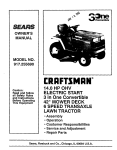
OWNERS
MANUAL
MODEL NO.
917,254710
CRnFTSMRN
Caution:
Read and Follow
All Safety Rules
And Instructions
Before Operating
This Equipment
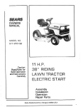
YT 14 TWIN CYLINDER
5 SPEED - 38" MOWER
YARD TRACTOR
• Assembly
• Operation
• Maintenance
• Repair
• Repair
, ii
,= =
i
,
S'e_ars, Roebuck
,,i,ii,l,
and Adjustment
Parts
lllunlul,,,,
and Coo, Chicago,
IL 60684
U 5 A.
SAFETY
RULES
1
Know the controls and how to stop quickly READ THiS
OPERA TOR'S MANUAL
and instructions furnished with
attachments.
2_ Do not allow children to operate the machine. Do not allow
adults to operate it without proper instruction.
3 Do not carrypassengers
Do not mow when children end
others are around.
4. Always wear substantial footwear. Do not wear loose fitling clothing that coutd get caught in moving parts,
5 Keep your eyes end mind on Four tractor, mower end the
area being cut. Do not let other interests distract you
6 Do not attempt to operate Your tractor or mower when
not in the drivers seat.
7, Always get on or off your traetor from the operator'o
feft
hand side,
El Clear the work area of objects {wire. rocks, eta ) which
might be picked up and thrown.
9. Disengage
all attachment clutches before attempting to
start the engine.
i 0 Disengage power to attachments
and stop the engine
before leaving the oparator'o position,
I I Disengage power to mower, stop the engine and disconnect spark plug wire{s) from spark plugis) before cleanm
• g • makmg an adjustment or repair Be careful to avoid
touching
hot muffler or engine components_
I 2o Disengage power to attachments when transporting or not
in use,
13 Take aU possible precautions when leaving the vehicle un.
attended. Disengage the power.take*bit,
lower the attachments,
shift into neutral, set the perking brake, stop
the engine and remove the key,
74, Do not stop or start suddenly when going uphill or
downhill. Mow up and down the face of slopes {not
greater than 15 =l; never across the face Refer to page 5 t
75., Reduce speed an slopes and make turns gradually to pro.
vent tipping or loss of control Exercise extreme caution
when changing direction on slopes.
76 While going up or down slopes, place Gear Shift Control
Lever in 1st gear position tO negotiate the slope without
stopping,
f 7., Never mow in wet or slippery grass, when traction is un,,
sure or at a speed which could cause a skid.
78 Stay alert for hotas in the tarrain and ether hiddan hazards
Keep away from drop.otis,
19 Do nor drive too close to creeks, ditches and public
highways,
20
Exercisespecialcarewhenmowingsroundfixedobjects
in order to prevent the blades from striking them Never
deliberately run tractor or m o wet into or over an y foreign
objects,
2 I Never shift gears until tractor comes to a stop.
22. Never place hands or feet under the mower, in discharge
chute or near any moving parts while {rector or mower
are running
Always keep clear of discharge chute
23,
Use core when pulling loads or using heavy equipment
a, Use only approved drswbar hitch points,
b, Limit loads to those you can safely control
c. Do not turn sharply. Use care when backing,
d, Use counterweight
or wheel weights when suggested
in the owner's
manual
24
Watch out for traffic when crossing or near roadways.
25
When using any attachments,
never direct discharge el
meteriat toward bystanders nor allow anyone near the
vehicle while in operation
2 6 Handle gasoline with care - it is highly flammable,
a, Usa approved gasoline containers
b, Never remove the fuel cap of the fuel tank or add
gasoline to a running or hot engine or an engine that
has not been allowed to cool for several minutes after
running. Never fill tank Indoors, always clean up spill.,
ed gasoline,
c Open doors if the engine is run in the gara[/e - exhaust
fumes era dangerous, Do not run the engme indoors.,
27
Keep the vehicle and attachments
in good operating condition, and keep safety devices in place end working,
2 El Keep olt nuts, bolts and screws tight to be sure the equip
,
ment is in safe working condition
29 Never store the equipment with gasoline in the tank Inside o building where fumes may reach an open flame or
spark. Allow the engine to cool before storing in any
enclosura
30
To reduce fire hazard, keep the engine free of grass, leaves
or excessive grease, Do not clean product while engine
iS running.
31, Except for adjustments:
DO NOT operate Engine if air
cleaner or cover directly
over carburetor air intake is
removed Removal of such pert could create a fire hazard.
32, Do not operate without a muffler or temper with exhaust
system. Damaged mufflers or spark arrestors could craete
a fire hazard Inspect periodically and replace if necessary,
33
The vehicle end attachments should be stopped end inspected for damage after striking a foreign object and the
damage should be repaired before restarIing and operating
the equipment°
34 Do not change the engine governo; settings or overspeed
the engine;' severe damage or injury may result_
35
When using the vehicle with mower, proceed as follows:
a. Mow only in dayfight or in good artificial light
b, Shut the engine off when unclogging
chute.
¢, Check the blade mounting bolts far proper tightness
at frequent; Intervals,
36, Do not operate the mower without the deflector shield in
place,
3 7 Disengage power to mower before backing up Do not
mow in reverse unless absolutely necessary end then On.
ly after careful observation of the ent#e area behind the
mower_
38, Under normal usage the grass catcher bag material is sub
ject to deterioration and wear. It should be checked frequently for bag replacement
Replacement bags should
be checked to ensure compliance
with the original
manufacturer's
recommendations
or specifications
LOOK
FOR THIS SYMBOL
TO POINT
OUT IMPORTANT
SAFETY
PRECAUTIONS,
IT MEANS - ATTENTIONI
BECOME
ALERTI
YOUR SAFETY IS |NVOLVED,
CAUTION:
LOOK FOR THIS WORD
MENT PR ECAUTIONS_
TO POINT
OUT IMPORTANT
EQUIP,
This unit is equipped with an internal combu_ion
engine and shouid not be used on or near any unimproved
forest
severed, brush covered or grat_ covered land unle_ the engine'_ exhaust _stem
is equipped with a spark arrestor
meeting applicable local or state laws (if any) If a spark armorer is used, it should be maintained in effective working
order by the operator
fn the State ot California
similar
taws Federal
the above
is raqulred
taws apply on federal
by law [Section
lands
Rater
4442 of the Caii/amie
to Repair
Pans
Section
Public
[Page
34)
Resources
Code)
Other states may
have
CONGRATULATIONS
on your purchase of a Sears 14HP
Yard Tractor. It has been designed, engineered and
manufactured to give you the best possible dependability
and performance.
sERIAL
NUMBER
DATE OF
PURCHASE
5houtd you experience any problem
you cannot easily
remedy,
please contact
your nearest Sears Service
Department,,
We have competent,
well-trained
technf.
cians and the proper tools to service or repair this unit
MAINTENANCE
Read and
keep your
welt cared
WILL BE FOUND
THE SEAT,
ON THE
YOU SHOULD
RECORD
THESE NUMBERS
KEEP FOR FUTURE REFERENCEr
AGREEMENT
A Sears Maintenance
Agreement
iS available
product.
See the nearest
Sears store or Service
for details,
CUSTOMER
THE SERIAL NUMBER
MODEL PLATE UNDER
AND
on this
Center
RESPONSIBILITIES
retain
this manual.
tractor
and mower
for tractor
will run
A TTA CHMEN
Study
and observe
the safety rules, Always
use care when using your
clean.
Follow
a regular
schedule
in maintaining,
caring
for, and using
better
and last longer.
tractor
Always
your tractor
A
TS
This unit can usa many attachments now available at your Sears store, It canuse a tiller, but cannot use other attachments
that engage the ground fike a prow,harrow, or cu/tivator_Sea page 50 for a fistof available attachment,s,.
LIMITED TWO YEAR WARRANTY
ON ELECTRIC START RIDING EQUIPMENT
Far two years from date of purchase,
when this riding equipment
is maintained,
lubricated,
according
to the operating
and maintenance
instruction
in the owner's
manual, Sears will repair
any defect
in material
or Workmanship
in this electric
start riding
equipment
This warranty e_cludes btadels}, blade adapteris),
dsbla and become worn during normal use
This
spark plugls},
air cleaner
and belHsi,
which
warranty
does not cover:
Tire replacement
or repair caused by punctures
from outslde objects
{such as nails,
or glass); and
repairs necessary
because
of operator
abuse or negligence,
including
the failure
equipment
according
to instructions
contained
in the owner's
manual:
and
riding equipment
used for commercial
or rental purposes
FULL 90-DAY
For 90 days from the date
in material
or workmanship
the battery
at no charge
WARRANTY
of purchase,
if any battery
and our testing
determines
and tuned up
free of charge
are expem
thornSo stumps,
to maintain
the
ON BATTERY
included
with this riding equipment
the battery
wilt not hold a charge,
proves defective
Sears will replace
WARRANTY SERWCE IS A VAfLABLE BY CONTACTING THE NEAREST SEARS SERVICE CENTER/DEPART.
MENT IN THE UNITED STA TES Thi,_ warranty applies only while this product is in use in the United States
This warranty
to state
gives
SEARS,
you specific
ROEBUCK
legal
and
rights,
CO,,
and you
may also have
D/698-731A,
Sears
other
Tower,
rights
which
Chicago,
may
vary
1160684
from
state
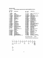
INDEX
Adjustments:
Brake
Carburetor
.
Mower Drive Belt
Mower
Front*To.Rear
Sfde.,To Stde ,,
Throttle Control Cable
Air Cleaner
Cleaning
, Paper Cartridge
.
Air Intake Screen, Engine
Assembly
,
Attachments
.........................
Battery:
Charging
Cleanlng
Installation
Levels
,
Preparation
.....
Starting with Weak Batlery
Storage.
Terminals
Belt:
Motion Drive Replacement
Mower Drive Adjustment
Mower Ddve, Removal
Blade:
Fuel:
Type
17
22
11
Storage
Fuse
13
26
22
25
24
21
Hood Removal
23
18
19
.18
5,I t
,50
21
18
: 8
I7
7
2f
26
tg
Farts Bag
Lubrlcatlen:
Chart
Tractor Pivot Points
Sharpening
Replacement
.....
Brake Adjustment
17
25
I7
C
Carburetor Adjustment.
Controls, Tractor
Cutting Level, Mower
22
12
tI
18
IB
tB
tB
13
26
0
Oil
Cold Weather CondMone
Engine......
Storage
Operation ........
,,
Operating Your Mower
Operetit_gYour Tractor
Starting the Engine
.....
Engine:
Air Screen
Oil Change
011 Level
Oil Type
Starting
Storage
,
..........
20
t9
Maintenance
:
....
Air Filter
Air Cleaner "Paper Cartridge
Air Intake Screen, Engine
gat_erv
Bfade*Sherpen}ng
Brake Adjustment
Engine Oil . .
Lubrication Chert
Spark Plugs
Tire Care
Mower:
Adjustment,
Front-to.Rear
Adjustment.
Side.to.Side
Blade Sharpening,
Blade Replacement
Cutting Level
Installation
Oparatlon
Removal
Muffler
.....
Spark Arrestor
23
tt
I0
Stopping Your Tractor ,
Tractor Operation on Hills
Options
Attachments
.................
Spark Arrestor
................
I6-20
IB
19
la
t8
17
I7
16
2g
19
17
,
25
24
I7
25
II
10
14
24
18
2
16
16
.26
, I245
,
14
f4
t3
13
15
50
2
5,B
Repair and Adjustments
20-26
glade
25
Carburetor
22
Fuse
.
22
Hood Removal
•
,
23
Motion Drive Bett Repfa_ement
23
Mower Adjustment,
Front-to-Rear 2El
Mower Adjustment,
Side,to,Side
24
Mower Removal
24
S
;
Safety Rules
Seat ....
Service Record
Slope Guide Sheet
Spark PloDs
,
Speed Control Chert
Starting the Englne
Staerittg Wheel
"
Stopping the Tre_tor
Storage
•
Throttle Control Cable Adjulttment
Tires ..........
Trouble Shooting Chart
2
7
28
51
1_q
14
13
. 8
I3
26
2I
17
2 2
W
Warranty
..................
W'_ng (Schematic!
3
29
Know
ASSEMBL Y
Your Tractor
READ THIS OWNER'S MANUAL BEFORE OPERATING YOUR YARD TRACTOR.
If you understand
the machine and its operation,
you will achieve efficient and peak performance_
While reading the
manual, compare the illustrations
with your Yard Tractor to familiarize
yourself with the location
,of various controls and adjustments,
Study the operating
instructions
and safety precautions
'thoroughly
to insure proper functioning
of your Yard Tractor and to prevent injury to yourself and
others. Be sure to pay strict attention
to all notes and cautions; they are included for your safety.
Save this manual for future,reference,
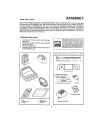
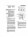
Unpacking
Instructions
The operation
1. Take items our of carton; the box contains the items
shown below,
2. Cut down four comers of the cation with a utilityknife
and fold down sides.
3. Disengage Parking Brake°
4 Carefully guide the tractor backwards off the skid. Be
careful of staples tn skid,
of any tra¢tor
can result
Parts
Bag
Contents
Not
Shown
Full
Size:
i!!!!!!!!!}!!!!!!)j!!!ll[![)l_j!/llltH!!llHtlfi)
t2i Battery
_.
Carriage
Bolts
d
f5 ° Slope Instruction
Sheet
{2) Keys
b
(6 J Battery Caps
c.
ba#_ry
wheel
d
e,
bMfety
ownat'e
_
pttrfa
acid
manu@}
bag
Steering Wheel Cap
|
- 1/4 - 20 x 7 - 1/2
Terminal Guard
a, sear
b, steeling
in
foreignobjectsthrown into the eyes,which
can result in Severeeye damage, Always
wear safety glasses
or eye shields before
starting your traetor andwhile mowing.We
recommendWide VisionSafety Mask worn
over spectaclesor standardsafety g/a_es,
availableat SearsRetailor Catalog Stores,
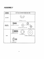
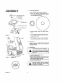
A SSEMBL Y
ASSEMBL Y
LOCATION
PARTS BAG CONTENTS SHOWN FULL SIZE
BATTERY
(21 Wing Nut - I/4 - 20
BA TTER Y
TERMINALS
t2} Hex Bolt, I/4
-, 20 x 3/4
©
©
(2) Washer 9/32
{2) Lockwasher
x 5/8 x 16 Ga
1/4
©
(21 Flex Nut,
(1) Lockwasher,
I/2
[2) Washer, 17/32x
SEA T
[ 1) Shoulder Bolt
I/4 - 20
I-3/16x
12 Ga.
Toassemble
A SSEMBL Y
and adjust your tractor you will need;
I2)
I)
(I)
(1)
(l)
7/16" wrenches
9/16" wrench
1/2" wrench
3/4" wrench
3!4"socket
Tire PressureGauge
Screwdriver
Utility Knife
Ratchet Wrench
CUTAWAYVIEW
BATTERY
NOTE: RIGHT HAND (R.H.) AND LEFT HAND (L.H.) ARE
DETERMINED FROM OPERATOR'S POSITION WHILE
SEATED ON THE TRACTOR.
BATTERY
WEAR EYE AND FACE SHIELD.
WASH HANDS OR CLOTHING IMMEDIATELY IF ACCIDENTALLY IN
CONTACT WITH BATTERY ACID,
FIGURE
7
DO NOT SMOKE= FUMES FROM
CHARGED
BATTERY ACID ARE
EXPLOSIVE°
READ THE INSTRUCTIONS iNCLUD_
ED WITH THE BATTERY VENT
CAPS IN THE BAG OF PARTS, ALWAYS WEAR GLOVES, CLOTHING
AND GOGGLES TO PROTECT YOUR
HANDS, SKIN AND EYES.
t.
BOLT
ADJUSTMENT
SEAT
FUEL
TANK
Prepare Battery
a. Fill and charge battery (before installing). NOTE:
SEE DETAILED INSTRUCTIONS
PACKAGED
IN BAG OF PARTS.
b
C.
d.
Fill each cell with battery acid. Add the acid until it reaches the bottom of the vent wells {Fig.
1). NOTE; DO NOT OVERFILL. OVERFILLING
WILL RESULT IN DAMAGE TO TRACTOR.
Allow battery to stand and settle for at least thirty minutes° If the level of acid falls below the
point described in step {b}, add more acid until
the correct level is reached. NOTE: UNEVEN
FILLING OF CELLS WILL AFFECT THE BATTERy
CAPACITY AND LIFE, Install the battery caps to
cover the vent wells. Wash the top of the battery with water to remove any acid, then wipe
dry.
Check battery case for leakage to make sure that
no damage has occurred in handling.
eo Itisrecommendedthatthebatterybechargedbafore
use, Use a 12 volt batten/charger, Charge battery at a
rate of 6 amperes for I hour. NOTE: OBSERVE ALL
SAFETY PRECAUTIONS REQUIRED FORBATTER Y
CHARGING. Check the acid level after the battery is
charged,ff the acid has latfen below the correct level,
add water,
f . Neutralize excess battery acid for disposal by
adding it to four inches of water m a five
gallon plastic container. Stir with a wooden or
plastic paddle while adding baking soda until
the addition of more soda causes no more
foaming.
FIGURE 2
2_
Install Seat
a. Place seat on seat pan. Screw adjustment bolt, shouk
der bolt, Iockwasher and flat washer into seat (fig. 2)°
Bolt _, leckwashe rand flat washer found in bag of parts.
hten shoulder bolt securely using a 1/2" wrench.
hten adjustment
bolt finger tight. NOTE: THE
SHOULDER BOLT WfLL BE LOOSE IN THE SEAT
PAN SLOT
b. Place seat in opel'ating position.
Sit on the teat
and press clutch/brake
pedal all the way down.
If operating position
is not comfortable,
ad/ust
seat.
c. To adjust, raise seat_. Loosen adjustment bolt
(Fig. 2} end slide seat to a comfortable
oper.
atingposition.
Tighten ad/ustmentbottsecumly
using a 3/4" wrench.
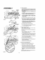
ASSEMBL
Y
3,
2 - 1t4"
DfA
LOCKNUT
WASHER
STEER;NG
WHEEL
STEERtNG
FIGURE
WHEEL
_NSERT
COLUMN
3
b
Position
insert,
c
Secure
2,1/4"
Torque
AiR
_
Wheel
NOTE; POSITION FRONT WHEEL FORWARD,
a Use a 3/4" wrench to remove hex nut, end
2 - 1/4"" diameter washer {shown full size below)
from steering column (Fig, 3j,
CAP
112 'o HEX
Install Steering
'.-_ r""_-.
steering
steering
diameter
to 50
wheel
over
steering
wheel
wheel
to steering column using
washer
and hex nut lFigo 3),,
ft - lbs_
d.. Snap steering whee! cap in place on steering
wheel Steering wheel cap found in bag of parts..
4,
Check Tires
Reduce tire pressure to 14 PS/ in front tires and
12 PSi in rear tires, (Tires were over inflated for
shipping purposes}°
Install Batter),
DO NOT SHORT BATTERY TERMINALS,
BEFORE INSTALLING BATTERY, REMOVE
METAL BRACELETS, WRISTWATCH BANDS,
RINGS, ETC.
FIGURE 4
a, Lift hood from rearside; (Fig. 4).
b. Lift out air lntake duct.
c. Make sure drain tube (Fig, 5) is fastened to drain
hole in battery
tray and battery
tray is positioned in hole of battery support.
d, Place battery in plastic tray (battery
terminals
to front of trector) (Fig. 5),
COMPARTMENT
[
FIGURE
4A
8
TED FIRST TO PREVENT SPARKS FROM
POSITIVE TERMINAL MUST BE CONNEC.
ACCIDENTAL GROUNDING.
ASSEMBL Y
e. Connect RED battery cable to positive (+)
battery terminal with bax bolt, fiat washer,
/ockwasher and hex nut (shown full size below)
found in bag of par_ (Fig_5). TlghWn securely.
f. Connect BLACK ground cable to negative (-)
battery terminal with remaining he,,,:bolt, flat
washer, lockwasher and hex nut (shown full
size below) found in bag of parts (Fig. 5),
Tighten securely.
.o@o
WASHER
NOTE:
IF YOU HAVE A WEAK BATTERY,
SEE "*STARTING
YOUR
TRACTOR
WITH
A WEAK
BATTERY"
(PAGE 21),,
g,
•
LOCKWASHER
Using the slotted hole on oneside of the battery
support (Fig, 6) insert onebattery bolt into frame
slot (head of bo# down), Fasten the battery bolt to
the terminal guard usingwingnut. (Bolts, nuts and
terminal guard found in bag of parts)
Assemble the remaining belt to other side of battory support and fasten terminal guard to it with
remainingwfngnut(shownfutlsizebalow)_ Tighten
wing nuts securelyby hand (Fig° 6),
h.
HEX
BOLTS
BATTERY
BOLT
FIGURE 5
/
SLOTTED
HOLE
_eemm
0
W_NG
NUT
/
L Replace air intake duct (Fig. 4)° Make sure
bottom llp of duct si= between battery and lip
of battery tray,
[ Remove plasb'c from tractor hood and close.
USE TERMINAL
ACCESS DOORS (FIG,, 6) FOR:
INSPECTION
FOR SECURE CONNECTIONS
(TIGHTEN
HARDWARE)
2, INSPECTION
FOR CORROSION
3 TESTING BATTERY
4. JUMPING
(IF REQUIRED)
5. CHARGING
OF REQUIRED)
WING
NUT
TERMINAL
ACCESS
DOOR
TERMINAL
GUARD
NOTE:
t.
bOLT
FIGURE
WHEN
NOT IN USEr
START
]
1
DO NOT
ENGINE
UNTIL
MOWER I
SUSPENSION
BRACKET
HAS BEEN
RE-[
LEASED,
SEE MOWER AND DRIVE
BELT |
KEEP
TERMINAL
AccEss
DOORS
CLOSED
I
INSTALLATION,
I
a
ASSEMBL
Y
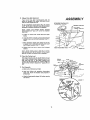
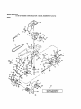
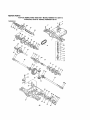
Mower Installation
6,_
Your 38" mower installs .without the use of tools.
Raise lift lever (Fig. 10) to its highestposlrion.
Turn height adjustment
knob (Fig. 9) to its
lowest position.
, .
.
eo Slide mower under tractor, discnarge guard to
R.H, side,
PARALLEL
LiNK
b. Install front hinge pin through axle and parellel
link (Fig. 7). Secure wfth retaine_ spdng_
c. Install rear hinge pln through mower lift brackets and parallel
link
(Fig, 7J. Secure with
retaln er spring.
HINGE
PIN
REAl
HINGE
FIGURE
d. Install clutch
FRONT
AXLE
rodin
clutch
lever (Fig. 8.
Inset)o
eo Move lift lever forward
to lower suspension
arms. Slide trunnlons
through
lift
bracket
holes end secure with retainer ;pring (Fig. 8).
7
f
Roll belt over engine pulley. Make sure belt
is inside belt guides [Fig. 9)_ See belt drive schematlc decal on mower housing.
g. Use lift
lever (Fig. 10} to raise mower,
h. Turn height adjustment knob (Fig. 9} clockwise
(f-_)
to the middle of its travel
7.
Mower
Drive
Belt Removal
NOTE:
MOWER
BELT
iNSTALLATION
LOCATED
ON MOWER HOUSING.
REPLACE
ONLY
THIS MANUAL.,
WITH
a, Place attachment
GAGED" positton
BELTS
SPECIFIED
clutch
lever
(Fig. 10)..
in
IN
"DISEN.
b. Torn height adjustment knob (Fig. 9] to lowest
position.
Move mower
rift lever (Fig.
lO)
forward to lower mo war to its lowest position.
TRU_NtON
FIGURE
THE
DECAL
e
co Roll belt off engine pulley
(Fig,
ful not to bend the belt guides,
\
d, Pull belt off both mandrels
t 1). Be care-
(Fig. ! 1).
e. Spring belt guide away from
pull belt off idler pulley,
idler
pulley
and
f. Slide belt from under idler spring.
8, Mower
Drive Belt Replacement
ao Slide belt under extension
b, Place belt on rearstde
spring (Fig, 11).
of both mandrels,
c_ Spring idler bait guide away from idler pulley
and p/ace belt around mar st'de of idler pulley,
d. Roff belt over mower drive pulley.
Make sure
drive belt is inside mower drive pulley
belt
guides.
NOTE: BELT GUIDE TO BELT CLEARANCE SHOULD
BE MAINTAINED AT 5/32 TO 1/4'L
FIGURE 9
I0
9_
ASSEMBL Y
Mower Ddve Belt Adjustment
Your tractor
has been manufactured
with the
ability to m_djust the mower drive belt to provide you with longer belt life.
ATTACHMENT
"DIS£NGAGE
If the attachment
clutch lever (Fig, 10) travels
3- I/2" up the slot in the dash before spring tension
resistanca is evident, adjustment is necessary.
CLUTCH
LEVER
D" POSITION
NOTE.* CHECK FOR PROPER SPRING TENSION
WITH ENGINE OFF AND L_FT LEVER IN HIGHEST
POSITION,,
a, Lower
or
remove
the mower
deck for easier
access,
b_ Using (2) 7/t6"' wrenches, remove the D-shaped
washers from the rock shaft assembly (Fig I i Inset).
e_ Move extension
spring from lower end of slot
to upper end in rock thaft assembly and install
the Doshaped washers (Fig., 1 t oInset},
do Tighten bolt and nut to secure the D.shaped
washer;,
HEIGHT
ADJUSTMENT
KNOB
FIGURE
t0
NOTE', WHEN
INSTALLING
A NEW BELT. EXTEN
SION SPRING MUST BE RETURNED
TO THE LOWER
END OF THE SLOT ON ROCK SHAFT ASSEMBLY
10. Check the Cutting Level
The blade housing was set at the factorF to cut
level, After mowing a short distance, look at the
area that was cut, If the blade housing cuts
uneven; see the instructions
on "Side.to,Side and
Front-to-Rear
Mower Ad[ustment"
(pages 24 and
25L
ENGINE
PULLEY
IDLER
1 Io Final Assembly
a, Make sure all fasteners are tight,
b_ Read and follow the operation instructions
(page 12). Know the location and purpose of
al! contmls.
c. Check oll and gasoline (page 13) before
the tractor,
starting
FIGURE
R.H_ PIVOT
BRACKET
BOLT
11
tI
OPERA T/ON
KNOW
YOUR
TRACTOR
READ THIS OWNER'S MANUAL BEFORE OPERA TING YOUR YARD TRACTOR°
operation, you will achieve efficient and peak performance,
While reading the
your Yard Tractor to familiarize yourself with the location of various controls
instructions and safety precautions thoroughly to insure proper functioning of
to yourself and others, Be sure to pay strict attention to all notes and cautions;
this manual for future reference,
If you understand
manual, compare
and adjustments.
your Yard Tractor
they are included
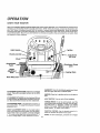
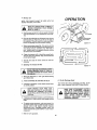
Light Switch
the machine and its
the illustrations with
Study the operating
and to prevent injury
for your safety, Save
Ignition
Throttle
_
Clutch/Brake
Pedal
Attachment
Lift Lever
Attachment
Clutch
Lever
He_ht
Adjustment
Knob
.... Parking Brake
Gear Shift Lever
GEARSHIFT: Press the clutch/brake pedal down firmly
and move gear shift laver to desired speed,
A TTA CHMENT CLUTCH LEVERz Push le var up to engage
mower. There will be an engine hesitation as the clutch
engages,
IGNITION*, Place key in ignition end turn to the right to
start.
A TTACHMENT LIFT LEVER: Use the attachment rift lever
to raise and lower the attachment mounted to. your tractor, Move the lift lever forward to tower attachment.
LIGHT SWITCH:
CLUTCH/BRAKE PEDAL: The pedal has 2 functions a
clutch and a brBke, To engage the brake push zhe peda/
completely down,
PARKING BRAKE: To set the parking brake, push the
clutch/brake pedal completely forward. Place the parking brake lever tn "Engaged"
position and release
pressure from pedal, Clutch/brake
pedal will remain in
brake poaitibn_ To release, push pedal in,
HEIGHT ADJUSTMENT KNOB: Use the height adjustment knob to adjust the mowar height. With the attachment lift lever in the "up"position, turn knob clockwise
{f"_} to raise cutting height and counterclockwise
(f_)
to lower cutting height Lower Attachment
rift lever
Turns on end off the headlights°
THROTTLE CONTROL: Use the throttle control
crease or decrease the speed of the engine,
to in-
CHOKE: To start a cold engine, puff choke out to engage_,
12
1, Stopping Your Tractor
OPERA TION
DO NOT CHOKE CARBURETOR TO STOP |
THE ENGINE,=
!
NOTE; REMOVE KEY WHEN LEAVING TRACTOR TO
PREVENT UNAUTHORIZED USE.
a. Push clutch/brake
pedal into full "'BRAKE'"
position,
b o Move gear shift lever to "'NEUTRAL" position.
c, Place parking brake in "ENGAGED*' position and
release pressure from clutch/brakeD Pedal should
remain in "BRAKE" posltion_ NOTE: MAKE SURE
PARKING
BRAKE WILL
HOLD
TRACTOR
SECURE.
d. Place attachment clutch leverin "'DISENGAGED"
positlon_
e o Move throttle control to "S" {slow) position.
f . Turn ignition key to "OFF" position. Never use
choke to stop engine_
2.
Starting
The Engine
GEAR SHtFT
: LEVER
LEARN TO START, STOP AND REVERSE
YOUR TRACTOR IN A LARGE, OPEN AREA.
12
FILL TO BOTTOM OF GAS TANK FILLER |
NECK. DO NOT OVERFILL, WIPE OFF ANY
SPILLED OIL OR FUEL. DO NOT STORE,
SPILL OR USE GASOLINE NEAR AN OPEN
FLAME.
THIS TRACTOR IS EQUIPPED WITH INTERLOCK SWITCHES TO PREVENT STARTING OF THE TRACTOR ENGINE WHILE
THE *'ENGAGED"
POSITION
THE
MOWER BLADE
CLUTCH AND/OR
LEVER IS
IN
FOOT PEDAL |S NOT FULLY DEPRESSED.
IMMEDIATELY REPLACE SWITCHES THAT
ARE NOT IN PROPER WORKING ORDER,
DO NOT ATTEMPT TO DEFEAT THE PUR......
POSE OF THE,_E SWITCHES. ,_,
a. This engine has been shipped filled with summer_ weight oil, For cold weather operation,
see chart on page 16, Check engine oil level
with
tractor
on level ground,
Remove and
wipe dipstick
(Fig, 17) clean, screw it in tight
for a few seconds, remote and read oil level,
If necessary, add oil until "FULL"
mark is
reached,
c,
Place attachment
clutch
lever tn "DISENGAGED" position (Fig° 12).
d, Push clutch/brake
pedal
fully
into brake
position.
eo Place gear shift /eter in "WEUTRAL " position
(Fig. 12).
f, Pull choke out (Fig. 12},
go Move throttle
control
to middle
position
(Fig, 72)_
h, Turn ignition key clockwise
((_-_) to "START"
position and release key as soon as engine starts,
NOTE: DO NOT RUN STARTER CONTINUOUSLY
FOR MORE THAN FIFTEEN SECONDS PER
MINUTE. If engine does not start after several attempts, move throttle
control
to "F" (fast)
position,
wait a few minutes and try again.
bo Fill fuel tank, Use fresh, clean, regular UNLEADED
automotive gasoline. (Use of leaded
gasoline will increase carbon and lead oxide
deposits and reduce
va/te life). Capacity
is
3-I/2 gallons°
CAUTION:
FIGURE
NOTE: tF YOU HAVE A WEAK BATTERY, SEE "START,
tNG YOUR TRACTOR WITH A WEAK BATTERY"
(PAGE 21)
EXPERIENCE
INDICATES
THAT
ALCOHOL
BLENDED
FUELS
(CALLED
GASOHOL
OR USING
ETHANOL
OR METHANOL)
CAN ATTRACT
MOISTURE .WHICH
LEADS
TO SEPARATION
AND FOR=
MATfON
OF ACIDS
DURING
STORAGE,
ACIDIC
GAS CAN DAMAGE
THE FUEL
SYSTEM
OF AN
ENGINE
WHILE
IN STORAGE
t
TO AVOID
ENGINE'PROBLEMS.
THE FUEL
SYSTEM SHOULD
BE EMPTIED
BEFORE
STORAGE
FOR
30 OAYS
OR LONGER,
DRAIN
THE
GAS
TANK.
START
THE ENGINE
AND LET IT RUN UNTIL
THE
FUEL
LINES
AND
CARBURETOR
ARE
EMPTY,
USE FRESH
FUEL NEXT
SEASON
SEE
STORAGE
INSTRUCTIONS
FOR ADDITIONAL
IN.
FORMATION
j
After engine is warm, push choke in. The first
time you start the engine, it will take extra crankIng time to move fuel from tank to the engine.
NOTE: ALLOW ENGINE TO WARM UP FOR A
FEW MINUTES BEFORE ENGAGING CLUTCH OF
TRACTOR OR ATTACHMENT
When restarting a warm engine, move throttle
control
midway
between
"_S" (slow)
and
"F"
(fast) positioned
Choke may not have
to be u_ed.
IMPORTANT:
NEVER
USE ENGINE
OR CARBURETOR
CLEANER
PRODUCTS
IN THE FUEL
TANK OR PERMANENT
DAMAGE
MAY OCCUR
13
BEFORE DRIVING THE TRACTOR,
INSTALL
MOWER
OR REMOVE
MOWER PARALLEL LINK (Fig° 7).
_
J
r
OPERA TION
,,,,,,, ,,
CAUTION:
ATTACHMENT
CLUTCH
"DIS£NGAGED'*POSITION
LEVER
UTCH
t
DO NOT ADD ADDITIONAL WEIGHT !
TO THE TRACTOR OTHER THAN THE l
OPTtONAL WHEEL WEIGHTS. EXCES. t
SIVE WEIGHT MAY OVERLOAD AND
DAMAGE THE TRANSMISSION.
LEVER
"ENGAGED"POSITtQN
{
J
3. Operating Your Tractor and Mower
NOTE: THIS TRACTOR
IS EQUIPPED WiTH AN
OPERATOR PRESENCE SENSING SWITCH. ANY AT.
TEMPT SY THE OPERATOR TO LEAVE THE SEAT WiTH
THE ENGINE RUNNING AND THE ATTACHMENT
CLUTCH ENGAGED WILL SHUT OFF THE ENGINE.
HEIGHT
ADJUSTMENT
KNOB
MAKE SURE PARKING BRAKE WILL HOLD
TRACTOR SECURE,
NEVER PLACE YOUR HANDS OR FEET IN
OR UNDER ANY POWERED ATTACHMENT
OR NEAR ANY MOVING PART WHILE
TRACTOR OR ANY POWERED ATTACHMENT IS RUNNING.
NOTE: ALWAYS OPERATE ENGINE AT FULL THROTTLE
WHEN MOWING TO ASSURE BETTER MOWING PERFORMANCE
AND PROPER DISCHARGE OF CUT MA
TERIAL. REGULATE GROUND SPEED BY SELECTING
A LOW ENOUGH GEAR (FIG. 14) TO GIVE THE MOWER
CUTTING PERFORMANCE
PLUS QUALITY OF CUT
DESIRED.
BGURE
13
J
_L
FUNCTION
L
Normal
Mowing
Heavy
Mowing
Snow
. B_ade
Snow Blower
or TiIler
Tt'aRsport
GEARSHIFT
....................
,L u,,,,
THROTTLE
lor2
1, 2or3
FAST
3,4or5
/. Move throttle control to "F" (fast) position.
NOTE: SELECT A GROUND SPEED THAT WILL SUiT
THE TERRAIN, QUALITY OF CUT AND ATTACHMENT
BEING USED_ (See Chart. Ftg. t4).
SLOW-FAST'
FIGURE
,
a, Select desired height of CUtposition using height
adjustment knob (Fig. 13).
b _ Raise lift lever and place attachment clutch lever
tn disengaged position_
c. Push clutch/brake pedal down firmly.
d. Start engine (page 13).
e o With engine running and warm place throttle contre/midway
between "S" (slow) and "F" {fast)
positton_
f o Engage mower with the attachment clutch lever.
NOTE: "ENGAGE"
DR "DISENGAGE"
MOWER
BLADE CLUTCH LEVER SLOWLY.
go Move gear shift lever to desired gear_
h. Lower mower into cutting position using ettaeh_
ment rift lever..
i o Release clutch/brake pedal to start movement
2or3
1
A
OUT EITHER THE ENTIRE GRASS
CATCHER,
ON
MOWERS
SO
EQUIPPED,
OR THE DEFLECTOR
DONOTOPERATETHEMOWERWITH"
SHIELD IN PLACE.
14
NEVER RUN THE ENGINE WITHOUT AIR INTAKE DUCT INSTALLED (FIG 4). MAKE
SURE BOTTOM LiP OF AIR INTAKE DUCT
SITS BETWEEN BATTERY AND LiP OF
BATTERY TRAY.
14
J
4, Mowing
Tips
NOTE: TiRE CHAINS CANNOT
MOWER HOUSING ATTACHED,
READ THE "SAFETY
BE USED WITH
RULES" CAREFULLY
BEFORE OPERATING
REFER TO PAGE 2.
YOUR
MOWER,
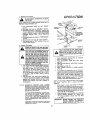
a.
Use the runner on the R.H.. side as e guide; the blade
cuts approximately
an inch outside the runner IFig.
15).
b.
Drive so that clippings are discharged onto thearea
that has been cut. Have the curates to the fight of
the machine. This will result in a more even distri.
but/on of clippings and more uniform cutting.
o,
OPERA TION
THE
DISCHARGE
GUARD
FIGURE
When mowing large areas (Fig. 16), start by turning
to the right eo that the clippings wllf dtsohsrge away
from shrubs, fences, driveways,
etc. After one or
two rounds, mow in the opposite direction making
left hand turns until flnished.
f
T
d. If grass is extremely
tall, it shoutd be mow_d tw/ce.
The first time cut relatively high; the second time
to the desired height_
e,
The left hand side of mower
trimming.
5,
Operating The Tractor On Hills
A
.........
a,
should be used for
FIGURE 16
Move gear shift lever to "' I ST" gear be fore starting
up or down hills_
OR SHIFTING
ENOUGH
ROOM
6.
ON HILLS,
If slowing is necessary, mov'e throttle
to slower position.
LEAVE
WHEN
Flip.Up Discharge Guard
Your mower has a flip-up discharge guard lFig_ 15) for
door or gate clearance when held tn raised position.
control lever
STOP°
A
TRACTOR ROLL DOWNHILL AS CLUTCH/
PiNG AND STARTING TO ALLOW SLIGHT
BRAKE PEDAL MOVES THROUGH CLUTCH
POSITION.
d° If stepping is absolutely necessary, push cfutch/brake
pedal quickly to brake position and engage parking
brake,
e.
r
DO NOTDRtVEUPORDOWN
HILLSWITH
LOPES GREATER THAN 15 ° AND DO
NOT DRIVE ACROSS ANY SLOPE. REFER
TO PAGE 61,
b . AVOID STOPPING
c.
15
To restart trector movement, make sure tractor is in
the lowest speed range 11st Gear) and that you have
allowed room to roll slightly downhill.
Depress
clutch/brake fully, Disengage parking brake and
release clutch/brake pedal SLOWLY to start tractor
movement,
f. Make all turns gradually_
15
MAKE SURE ATTACHMENT
CLUTCH
LEVER IS IN "DISENGAGED"
POSITON
AND BLADES HAVE STOPPED BEFORE
RAIS|NG DISCHARGE GUARD IDEFLECTOR) ..... NEVER ,_OPERATE
_MQ_WER
WITHOUT
DISCHARGE
GUARD
IN
OPERATING POSITION,
MAINTENANCE
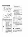
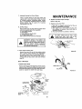
With Every Mowing
1_ Make sum all nuts on bolts am tight and cotter
pins and retainer spdngsare secure.
2, Observeall safety precautions,
3o Keep tractor we!l lubricated fmfer to page 20jo
First 2 Hours (Two
Mowings)
1. Change Engine Oil
Changing oil after the first two hours (or two mowinge) will help eliminate break-in residue which might
be damaging to your engine.
NOTE: BE CAREFUL NOT TO ALLOW DIRT TO ENTER
THE ENGINE WHEN CHANGING OIL,
ENGINE
OIL
DIPSTICK
AND FILL TUBE
FIGURE
17
a Drain oil with engine warm,
b, Loosen off drain wing nut [Fig, t8} end remove
dipstick,
c. Catch oil in a suitable container,
do Tighten oil drain wing nut.
e. Refill engine otL See off chart, below, Refill capeck
ty is 1-I/2 quarts. NOTE: DO NOT OVERFILL.
f. Replace dipstick°
Recommended
SAE
Viscosity
Grades
Determine temperature range expected before next oil
change. All oil must meet A.P..L service classification SD,
SE or SF.
.20_
FIGURE 1B
0_
32 _
60 _
80 °
!00 _
To keep
your tractor
running
better,
longer, perform necessary service using
the following maintenance
schedule:
BEFORE MAKING ANY INSPECTION,
ADJUSTMENT OR REPAIR:
1,
PUSH TRACTOR CLUTCHIBRAKE
PEDAL
COMPLETELY
INTO
"BRAKE" POSITION_
2,
MOVE GEAR SHIFT LEVER TO "N"
NEUTRAL POSITION.
3.
PLACE PARKING BRAKE IN "ENGAGED"
POSITION,
REMOVE
FOOT FROM PEDAL,
PLACE ATTACHMENT
CLUTCH
LEVER IN "DISENGAGED"
POS1TION_
4.
5,
TURN
POSITION.
IGNITION
SHUTKEY
OFFTOTHE"OFF"
ENGINE.
6,
MAKE ABSOLUTELY
SURE THE
BLADE AND ALL MOVING PARTS
HAVE COMPLETELY STOPPED,
7,
REMOVE THE IGNITION
8,
DISCONNECT THE SPARK PLUG
WIRES FROM THE SPARK PLUGS
AND KEEP WIRES AWAY FROM
THE PLUGS TO PREVENT INJURY
FROM ACCIDENTAL
STARTING,
BE CAREFUL TO AVOID TOUCHING HOT ENGINE OR MUFFLER
COMPONENTS.
Capacity is I-I/2 quarts° NOTE: DO NOT OVERFILL.
Dipstick assembly must be securely tightened into tube
at aft times when engine is operating_
.........
CAUTION:
TO _,VOiD DAMAGE TO THE STARTING
SYSTEM, USE SAE SW30 OIL WHEN
THE TEMPERTURE FALLS BELOW 32 °
Every 5 Hours (Five Mowings)
1. Check Engine Oil Level
!
DO NOT CHECK ENGINE OIL LEVEL I
WITH ENGINE RUNNING.
I
KEY,
Several minutes after stopping engine, check engine
ell level with tractor on level ground, Wipe dipstick
(Fig 17) clean, screw it down tight for a few seconds/,
remove and read oil level If necessary, add oil until
"FULL"
mark is reached. (See chart above). NOTE:
DO NOT OVERFILL.
1R
Every 25 Hours (Twice
a Mowing
Season)
MAINTENANCE
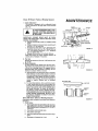
1_ Brake Adjustment
This tractor is equipped with an adjustable brake
system mounted on the right side of the transaxle
(Fig. 191_
BRAKE
OPERATING
BRAKE
ROD
ARM
JAM
NUT
NUT"A
SIX FEET STOPPING DISTANCE IN
HIGHEST
GEAR,
THEN BRAKE
IF TRACTOR
REQUIRES
MORE MUST
THAN ]
BE ADJUSTED,
_
IMPORTANT:
PARKING BRAKE MUST BE DISENGAGED AND GEAR SHIFT LEVER IN NEUTRAL WHILE
MAKING ADJUSTMENT.
a_ Depress clutch/brake pedal end engage parking
brake.
b, Measure distance between brake operating arm
and nut "A" on brake rod.
C. If distance is other than 1- I/2"; disengage parking brake, loosen jam nut (Fig. f9) and turn nut
"'A" until distance becomes 1-t/2", Retlghten
jam nut against Nut "A"°
d. Engage parking brake and recheck distance.
Road test tractor for proper stopping distance as
stated above, Readjust if necessary,,
DRAKE ENGAGED)
FtGURE
Tire Care
Maintain tire pressure in front at 14 PSI and rear tires
at 12 PSI,
3. Blade Sharpening
For best results mower blades must be kept eharp_
The blades can be sharpened with a few strokes of
a flle or on a grinding wheel,. We suggest they be
sharpened after every 25 hours of mowfng_ Do not
attempt to sharpen while on mower.
a. When grinding, care should be taken to maintain
blade balance and the blade should be checked
for'proper balance before reinstallstion on mower.
Unbalanced or bent blade will cause excessive
vibration when running, end eventual damage to
mower or engine. Replace bent or damaged
blades,
19
2.
FIGURE 20
CUTAWAYViEW
b. To check blade balance, drive a nail into a beam
• or well Leave'about one inch of the straight nail
exposed. Place center hole of clean blade over the
head of the nail (Fig. 201, NOTE: CENTER HOLE
OF BLADE ON NATL. IF BLADE iS PROPERLY
BALANCED, BLADE SHOULD REMAIN IN POSITION SHOWN IN FIG. 20, IF EITHER END OF THE
BLADE MOVES DOWNWARD,
BLADE IS NOT
BALANCED. SHARPEN THE HEAVY END UNTIL
BLADE 1S BALANCED ....
L ................
BAT3'ERY
TUBE
BATTERY
CELL
Every 60 Hours
(Once a Mowing
Season)
(Operating in dusty conditions may require more frequent
servicing.)
1o Check Battery
a. Acid solution level in each battery cell should be
even with bottoms of tubes in ceils (fig. 21). Add
ONL Ydistilled waterifnecsssaryo NOTE: DO NOT
OVERFILL.
b,
Keep battery and terminals clean.
c.
Keep battery bo/ts tight,
d,
Keep vent caps tight and emall vent holes in caps
open.
e,
Recharge
at 6 amperes for I hour
_P" VENT CAP
FIGURE 21
17
MAINTENANCE
2o Clean Battery and Terminals
Corrosion and dirt on the battery and terminals cause the
battery to "leak" power°
LEAD.ACID
BATTERIES
GENERATE
EXo
PLOSIVE
GASES.
KEEP SPARKS,
FLAME
AND SMOKING
MATERIALS
AWAY FROM
BATTERIES,
ALWAYS
SHIELD YOUR EYES
AROUND BATTERIES.
a. Remove terminal guard,
b. Disconnect BLACK battery cable then RED battery cable and remove battery from tractor,
c. Wash battery with four tablespoons of baking
soda to one gallon of water, NOTE:' BE CAREFUL
NOT TO GET THE SODA SOLUTION INTO THE
CELLS.
d.. Rinse the battery
with plain water, dry and
reinstall on tractor,
e . Clean terminals and battery cable ends with wire
brush until bright
fo Replace battery cables, connecting RED battery
cable to positive terminal first, then BLACK bat_
tory cable to negative terminal Coat terminal connections with Vasotineo
g, Replace terminal guard,
PRE,CLEANER
BODY
FIGURE
3.
Change Engine Oil
The best time to change engine oil is at the end of
a day's operation when all dirt and foreign materlalB
are suspended in the hot oil. See chert, page 16.
22
4,
GREASE
_FRONT
BOTH
WHEELS
*
X
.}
1
/
Clean Air Cleaner Foam Pro_Cfeansr (Fig, 221
a. Remove knobs and cover.
b. Remove foam pm-cleaner element by sliding it
off of the paper cartridge.
co Wash foam pro-cleaner in liquid detergent and
water.
d. Wrap foam prO.cleaner in cloth and squeeze dry.
e. Lightly coat foampre_leaner
with englneo//o
Squeeze in towel to remove excess oil Do not
saturate,
f. Install foam pro=cleaner over paper cartridge,
g. Reassemble cover and screw down tight.
O_L
_GURE
B. Clean Air Screen
Air screen (Fig, 22) must be kept free of dirt and chaff
to prevent angina damage from overheatlng_ Clean
with a wire brush or compressed air to remove dirt,
stubborn dried gum fibers,,
SPINDLES
23
e,
Check Muffler
Inspect and replace corroded muffler
create a fire hazard and/or demage_
_
18
as it could
CYLINDER OR FINS AS CONTACT MAY
DO NOT
TOUCH
HOT
MUFFLER,]
CAUSE BURNS,
7,
Lubricate
Steering
And
Front
MAINTENANCE
Wheels
There is a grease fitting on each front wheel. Use
a greasegun to give each grease fitting two shots
of extreme pressure lubricating grease Amdex
No, I or equivalent (available through your Sears
Service Center), Use 30 weight ott to lubricate
front si_indles(Fig, 23),
2o Replace Air Cleaner Paper Cartridge
(Refer to Page 18).
3o Replace In-Line
If fuel filter is clogged, obstructing
fuel flow to
carburetor, replacement is required.
a, With engine cool, rereove filter and plug fuel
line sections as removed from both ends of
fuel filter (Fig. 26}
b° Place new fuel filter in position in fuel line,
8_ Oil Pivot Points
Place several drops of SAE 30 oi/atpn/nts
parts move against each other, especially."
an Front wheet sptndles,
b, Hood hlnges.
c. Foot pedal shaft (both ends).
do Lift shaft (both ends).
SEE L UBRICA TION CHAR 7", PA GE 20,
where
I
J
LEAKS AND THAT FUEL LINE tS IN
BE
SUREPOSITION
THERE INARE
NO
FUEL "LtNE I
PROPER
HOSE
CLAMPS.
I
PREVENT
_k
ACCIDENTAL
STARTING
Fuel Filter
""
BE-_
__
I"",,/"_
F,030'_FEELe"
FORE MAKING
ANY INSPECTION,
ADJUSTMENT
OR REPAIR
{EXCEPT CARBURE-|
DISCONNECT
SPARKTO PLUG
TO JI
TOR).
BE CAREFUL
AVOID WIRE{S)
TouCHING
l
HOT ENGINE CQMPONENTS_
j
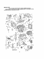
9. Clean Engine Cooling Fins
FIGURE 25
Remove any dust, dirt or oil from engine cooling
fins to prevent engine damage from overheating.
Air guide cover; must be removed,(Fig 24)
Remove eight 7/I6" bolts and six 5/16" bolts to
remove side and top covers. See hood removal,
page 23,
Every
\
100 Hours
HO_E
1. Replace
Spark Plugs
Replace spark plugs at the beginning
HOSE CL
of each mowing
season or avery 100 hours, whichever comes first. Gap
should be set at 0_030 Inch (Fig,25LA deep well 13/I8
socket is required to remove the spark plug.
FUI[t, F|LYER
FIGURE 26
OP AIR
GUIDE
COVER
FIGURE
24
19
MAINTENANCE
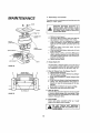
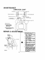
LUBRICATIONCHART
--SPINDLE
(_
® w,,.L
"-'---_WHEEL
(_) MDWER CLUTCH PIVOT
(
BEARINGS _
_-:
I--BOTH ENDSOF
\_J
FOOT
PEDAL
SHAFT
......
{.-.3..=._
L
f
1|
......
OLUTc.
PIVOT@
_'_'lr_sr_''L'--_'*
---'_
DS LIFT SHAFT (_
EXTREME PRESSURE
LUBRICATING GREASE
AMDEX NO, t, SEARS
PART NO 2557R
_
REFER TO ENGINE OIL SPEC'$.
IUNDER |N{TiAL PREPARATION
IN OWNERS MANUAL)
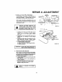
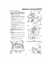
REPAIR & ADJUSTMENT
BEFORE MAKING ANY INSPECTION,
ADJUSTMENT OR REPAIR:
1.
PUSH TRACTOR CLUTCHIBRAKE
PEDAL
COMPLETELY
INTO
"BRAKE" POS_TION_
2.
MOVE GEAR SHIFT LEVER TO "N"
NEUTRAL POSITION,
3.
PLACE PARKING BRAKE IN "ENGAGED"
POSITION.
REMOVE
FOOT FROM PEDAL.
4,
PLACE ATTACHMENT
CLUTCH
LEVER IN "DISENGAGED"
POSITION.
5. TURN IGNITION KEY TO "OFF"
POSITION.
SHUT OFF THE ENGINE,
6_ MAKE ABSOLUTELY
SURE THE
BLADE AND ALL MOVING PARTS
HAVE COMPLETELY STOPPED,
7, REMOVE THE IGNITION KEY.
8,
FIGURE27
20
DISCONNECT THE SPARK PLUG
WIRES FROM THE SPARK PLUGS
AND KEEP WIRES AWAY FROM
THE PLUGS TO PREVENT iNJURY
FROM ACCIDENTAL
STARTING,
BE CAREFUL TO AVOID TOUCHING HOT ENGINE OR MUFFLER
COMPONENTS.
REPAIR & ADJUSTMENT
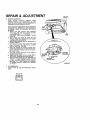
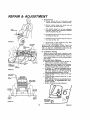
1_ Starting your Tractor W/lh e Weak Battery
If your battery is too weak to start the engine, it
should be recharged, If "_umper cables" are used
for emergency starting, follow thisprocedure:
NOTE;
YOUR
TRACTOR
IS EQUIPPED
WITH
,_, 12
VOLT NEGATIVE
GROLINDEO
SYSTEM. THE OTHER
VEHICLE
MUST
ALSO BE A =t2 VOLT
NEGATIVE
GROUNDED
SYSTEM,
LEAD.ACID
BATTERIES
GENERATE
EX..
PLOSIVE
GASES. KEEP SPARKS,
FLAME
AND SMOKING
MATERIALS
AWAY FROM
BATTERIES°
ALWAYS
WEAR
EYE PROTECTION
WHEN AROUND
BATTERIES.
a_ Connect each end of the RED cable to the
POSITIVE
(+) terminals of each battery
(taking care not to short against chassis)
(Fig 27j
b, Connect one end of the BLACK cable to the
NEGA TIVE (-) terminals of fully charged
battery,
co Connect the other end of the cable to the L.H,
side pane/ bolt (Fig. 28J
NOTE: KEEP
AWAY FROM GAS TANK AND BATTERY.
do Disconnect cablesin reverseorder:
I, L.H_ side panel bolt (Fig. 28)_
2, Negadve terminals of fully charged batten/o
3. Posidveterminals:
IDLE SPEED
SCREW
MIXTURE
VALVE
GOVERNOR CONTROL
L_VER
FIGURE
|MPORI"ANT; DO NOT USE YOUR TRACTOR BAT. I
.
2,
t ,Y ToSTA,'r
OT" "W"'CL SI
J
Throttie Control Cable Adjustment
Never attempt tO change maximum engine speed.
This is preset at _e factory
(3600 ± 100 RPMJ
and shou/d only be changed by a qua/ified service
technician who has the necassarF equipment.
a. Remove hood, page 23.
b. Loosen casing clamp screw until throttle
cable
is free to move,
c, Move throttle
control (on the dashboard) to
"FAST" posiu_on,
dr Pull throttle cable light (until swivel beneath
carburetor is against side of quarter clrcle)_
Retlghten casing clamp screw,
_
REFER13oTO
PAGE
"STARTING
THE
ENGINE,"}
21
29
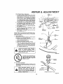
REPAIR & ADJUSTMENT
3,
Carburetor
Adjuslment
NOTE:
ADJUST
THROTTLE
CONTROL
CABLE
BEFORE
MAKING
ANY
ADJUSTMENT
TO CAR_
BURETOR,
AIR CLEANER
MUST BE ASSEMBLED
TO
CARBURETOR
WHEN RUNNING
ENGINE
Minor carburetor adjustments may be required to
compensate
for differences in fuel, temperature
or altitude° Adjust the carburetor
fuel mixture
as follows:
a° Gently
turn
idle mixture
valve clockwise
(_**)
fFia 30) until it just closes and then
counterclockwise
( ,_-- ) 1-1/2 turns.
CAUTION;
Valve may be damaged if turned
in too far.
b. Start
engine and allow
to warm for five
minutes.
Make final adjustments
with engine
running and choke pushed in.
co Move throttle control lever (on dashboard)
to
"SLOW " position.
d, Hold governor control
lever against idle speed
_erew, and adjust idle speed screw to obtain
1200 to !400 RPM (Fig, 29).
e, While still holding the governor control lever
against idle speed screw, turn idle mixture valve
slowly clockwise _-_ ){lean mixture) until speed
just starts to stow,
f, Turn idle mixture valve back to the midpoint
between rlch and lean.
g. Adjust
the idle speed screw to obtain 900 to
1200 RPM, Release governor control lever,
h, Move throttle
control
(on the dashboard)
to
"FAST."
If engine hesitates or dies, tum idle
mixture
valve approximately
i/8 turn counterclockwise
(,_")
until engine will accelerate
as throttle
control
is moved from "SLOW"
to "FAST, "
4.
Fuse Retgecement
Replace
fuse.
with
30
amp
automotlve.type
plug.in
22
REPAIR & ADJUSTMENT
5.
Motion
BELT
Drive Belt Replacement
The tractor drive belt may be replaced without tools°
Park the tractor on level area Engage parking brake,
NOTE: BELT INSTALLATION
DECAL UNDER LEFT
FOOTREST.
am Remove mower. (See page 24).
b
Remove two retainer springs from belt guide
bracket below transaxie pulley, Remove bracket
(Fig 31)
c
Swing belt guides away from belt, toward rear of
tractor {Fig_ 3 I)
d, Roll belt over top of transexle
e.
pulley
Roll belt over engine pulley and off idler (Fig_ 33),
f . Release parking brake.. Pull belt as far as possible
over top of clutch pulley
SHIFT
FIGURE
32
ENGINE
PULLEY
g. Reset parking broke. Pull belt over top of clutch
pulley {Fig 33)
h, Pull bett out through shift gate to remove from
tractor {Fig. 32},
Install belt by reversing above procedure.
NOTE: REPLACE ONLY WITH BELT LISTED IN
MANUAL.
6, Hood Removal
a, Lift hood. Disconnect
iFig. 35L
GATE
DRIVE
BELT
SCHEMATIC
CLUTCH
PUL
headlight wiring connection
b, Urrscrew one screw at rear of eash side panel {Fig,
34),
L H, SIDE
c. Pivot hood and side panel forward and lift off tractor {Fig° 35).
d, To replace, reverse the above procedure,
REAR
BELT
TRANSAXLE
PULLEY
f
RETAINER
SPRING
VIEWED
FROM
BOTTOM
OF TRACTOR
FIGURE33
I
BELT GUIDE
BRACKET
RETAINER
SPRING
FIGURE 31
FIGURE 34
23
REPAIR & ADJUSTMENT
7. Mower Removal
a, Remove mower belt per instructions
under
"Mower
Drive Belt Removal" through step(c).
b, Remove retainer spring from clutch
clutch rod out of clutch bracket,
e_
d_
rod;' pull
Puff retainer springs out of rear suspension
trunnions. Remove rear suspension trunnlons
from lift brackets (Fig, 36)°
Purl retainer spring out of rear hinge pin. Remove
rear hinge pin (Fig, 36).
e, Pull retainer sprlng out of front hinge pin. Remove
front hinge pin (Fig,, 361.
FIGURE 35
f_ Use rift lever to raise suspension arms_ Slide
mower out from under tractor.
NOTE: 1F AN ATTACHMENT
OTHER THAN THE
MOWER DECK IS TO BE MOUNTED ON THE TRACTOR,
THE Loll, AND R.H, SUSPENSION ARMS |FIG, 36)
SHOULD BE REMOVED FROM TRACTOR,
RETAINER
SPR}NG_;
RH.
8.
HINGE
PINS
ROD
FIGURE 38
LIFT
LEVER_
PLUNGER
F--
Level Mower Housing
Adjust the mower while tractor is parked on level
ground or driveway,, Make sure tire pressures are 14
PSi in front tires end 12 PSI in rear tires. If tires are
over or under inflated, you will not properly adjust
Four mower,
Side.to.Side Mower Adjustment
am Depress lift lever plunger end use lift lever to
raise mower to maximum cutting height,
b, Measure height from bottom of curl to ground
lave! at front of roD ware Distance "A " should be
the same on both sides of mower IFigo 37).
c. If distance ",4" needs to be ehan_d,
snap out
access hole cover on L,Ho side above footrest,
Use 11/16" wrench on nuts "B" and "C" at
side-to-side adjustment trunnion
(Fig, 38),
d, To raise left side of moor,
loosen nut "/]"and
tighten nut "C'",
e. To lower left side of mower, loosen nut "'C" end
tighten nut "B';
NOTE: ONE ROTATION OF ADJUSTMENT NUTS
IS EQUIVALENT
TO APPROXIMATELY
3/16"
HEIGHT CHANGE°
f _ Be sure all nuts are securely tightened.
BOTTOM
_
_-.._TA
GROUND
LEVEL
FIGURE
GROUND
LEVEL
_;IDE.TO*SlDE
ADJUSTMENT
,_
NUT
"_R"
37
TRUNNION
24
RGURE
3B
REPAIR
& ADJUSTMENT
Front-To.Rear Mower Adjustment
a To obtain the best cutting results, your mower
housing should be adjusted So the front and rear
flange distance "'D" (Fig, 391 is 1/2"" lower in
front when the mower is positioned in the highest
cutting position. NOTE: MEASURE DISTANCE
"D °" FROM GROUND LEVEL TO BOTTOM OF
CURL ON RIGHT REAR FLANGE AND COMPARE
TO DISTANCE "D" AT RIGHT FRONT FLANGE
b. To raise rear of mower, Ioosannut "E"on both
rear suspension arms. Screw bdth nuts "F" up
an EQUAL NUMBER
OF TURNS (Fig. 40).
c. When distance "D" is I/2" lower at front than
rear, tighten nuts "E."_
do To lower rear of mower, loosen nut "F" on
both rear suspension arms an EQUAL
NUMBER OF TURNS (Fig_ 40).
e. When distance "D" is l /2" lower at front than
rear, retighten nuts "E"
$
"_LrFT
6RACKET
REAR
SUSPENSION
TR_JNN_ON
GROUND
LEVEL
BOTTOM
OF CURL
FIGURE 39
NOTE: WHEN ADJUSTING REAR SUSPENSION TRUNNfONS, ALWAYS ADJUST BOTH EQUALLY SO MOWER
WILL STAY LEVEL.
9,
Blade Replacement
Raise mower to highest position
to permit access
to blades or remove moor
(page 24)..
a. Remove bolt, lockwasher end washer (Fig_ 41)
(turn counterclockwiselii_-_)o
b. Remove and discard old blade..
c Clean top and bottom of mower housings.
d Place new blade between flanges, (the word
"TOP" is stamped on afl blades to assure proper
installation), and secure with washer, lockwasher
and bolt previously removed. TIGHTEN SECURELY. Torqbe to 30-35 ft.. Ibs.
A
REAR
SUSPI
TRUNNION
NUT
LIFT
"F
ALWAYS
USE GRADE 5 HEAT TREATED
BOLTS
TO
ATTACH
BLADES,
CHECK
BOLTS
tN BLADES
OCCASIONALLY
TO
MAKE SURE BOLTS ARE TIGHT. TORQUE
BOLTS TO 30-35 FT, LBS,
FIGURE 40
A GRADE 5 HEAT TREATED BOLT
CAN BE IDENTIFIED BY THREE
LINES ON THE BOLT HEAD AS
SHOWN AT LEFT°
10,
Roar Wheel Installation
Coat axle with grease to prevent corrosion or rust
accumulation
and eventual seizing of wheel hub
to axle shaft.
WHEN
REPLACING
WHEELS
ON
THE
TRACTOR,
THEY
MUST
BE MOUNTED
WITH THE LONG HUB SIDE TOWARD
THE
CENTER
OF THE TRACTOR.
INCORRECT
INSTALLATION
COULD AFFECT
LATERAL
STABILITY_
{SEE FIG°44L
FIGURE 41
25
REPAIR
& ADJUSTMENT
11o Tire Care
D,, Battery
a Maintarn
tire pressure of t4 P.51 m front _res
and 12 PSi in rear tires
b, Keep tires free of gasohne, oil, or insect control
chemicals which can harm rubber.
c. Avoid
stumps,
stones, deep ruts an_ other
hazards that may cause dre damage.
d, Removing front wheel for tire repair (Fig. 42):
-=-Block up front axle securely,
.... Remove hub cap, klip ring and washer to
allow wheel removal,
.... Repair tire and reassemble, Replace washer
and snap klip ring securely in axle groove,
Replace hub cap,
e, Removing rear wheel for tire repair (Fig 43):
.....Block up rear axle securely,,
-*° Remove hub cap, E-ring and washer to allow
wheel removal
.... Repair tire and reassemble, While maintaining
key position,
replace washer and snap E-ring
securely in axte groove. Replace hub cap,
ARE
SEATED,
OVER
INFLATION
WHEN MOUNTING
CAUSE
AN EXPLOSION,,
TIRES_ UNLESS
_
!Z
I, Prior to storage,
battery,,
clean
terminals
and
top
2 After a period of time in storage, battery
require recharging.
of
may
E_ General Cleaning
Clean eng[ne,
foreign matter
F,
battery',
seat,
finish,
etco of
all
Store in a Clean Dry Area
CAN
BEADS 1
FIGURE
42
Storage
Remove mower from tractor for winter storage,
When mower is to be stored for a period of time,
clean it thoroughly,
remove all dirt, grease, leaves,
etc. Give blades and unde_ide of housing a good
coat of grease or rust preventative
Store in a
clean dry area°
A.
Fuel
System
WASHER
IT IS IMPORTANT
TO PREVENT
GUM DEPOSITS
FROM
FORMING
IN ESSENTIAL
FUEL SYSTEM
PARTS
SUCH AS
THE CARBURETOR,
FUEL FILTER,
FUEL HOSE,
OR TANK
DURING
STORAGE,
ALSO,
EXPERIENCE
INDICATES
THAT ALCOHOL
BLENDED
FUELS
(CALLED
GASOHOL
OR
USING
ETHANOL
OR METHANOL)
CAN ATTRACT
MOISTURE WHICH
LEADS
TO SEPARATION
AND FORMATION
OF ACIDS
DURING
STORAGE.
ACIDIC
GAS CAN DAMAGE THE FUEL
SYSTEM
OF AN ENGINE
WHILE IN STORAGE. TO AVOID
ENGINE
PROBLEMS,
THE FUEL SYSTEM
SHOULD
BE EMPTIED
BEFORE
STORAGE
FOR 30 DAYS
OR LONGER
HUBCAP
FIG (]RE 43
B. EngineOg
Drain (with engine warm) and replace with clean
engine oil (See chart, page 16).
t
O
'"i'
Co Cylinder=
I, Remove spark plugs,
2_Pour one ounce of oil through spark plug holes
into cy/inderso
3, Turn ignition key to "START"
few secondsto distribute oil
L
'
LONG
position for a
HUe
L..2
FIGURE 44
4, Replace with new spark plugs.
26
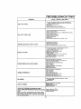
TROUBLESHOOTING"
PROBLEM
CAUSE
/ REMEDY
(SEE
INDEX)
Fill
Tank with Gasoline, Check Fuel Line and Carburetor
(clean if necessary), Replace Fuel Filter
Use Fresh Fuel
Recharge or replace Battery
Check Wiring
Replace Spar# Plug(s) and adjust gap
Drain and replace oil for proper tempera rure
WILL NOT START
Push Clutch/Brake
Pedal into brake poaition
Charge or replace Battery
Move Arteehment Clutch Lever to "DISENGA GED "position
Replace Ignition Switch
Replace Interlock
Switchfes)
Replace Solenoid or Starter
Replace .Spark Plug(s}
Replace Fuse
Check all Wire Connections and "'Ground" Points
r',/tLLNOT TURN OVER
ENGINE CLICKS BUT WON'T START
Clean Battery Termlna/s
Replace Starter or Solenoid
Charge or Replace Battery
Check Wire Connections and "Ground'"
Points
HARD TO START
Place Throttle Control in "FAST'position
and run
starter leveret times to clear cut gas
Remove Air Filter and clean
Replace Spark Plug(s) and adjust gap
Recharge or replace Battery
Check the Wiring
Drain Fuel Tank and Carburetor, Use Fresh FueL,
Replace Fuel Filter
Make necessary adjustments
to Carburetor
Major Engine Overhaul
ENGINE MISSES OR LACKS POWER
Shift to a lower gear or reduce feed
Drain Gas Tank and Carburetor
Use Fresh Fuel
Rome ve at_d clean Air Cleaner
Make necessary carburetor adjustments
Clean Air Screen
Add or change oil
Replace Spark Plug(s) and adjust gap
Replace Fuel Filter
Major Engine Overhaul
ENGINE OVERHEATS
Shift to Iower gear or reduce load
Clean Air Screen
Add or change oil
Clean Engine Cooling Fins
Remove and clean Muffler or replace
Remove and clean Air Ftlter
U_e fresh fuel and adjust Carburetor
NO LIGHTS
Cheek Fuut, Switch and Wire Connections.
Headlight Bulbs
Replace Switch
WON'T CHARGE
OPERATOR PRESENCE SYSTEM W! LL NoT
SHUT DOWN ENGINE WHEN OPERATOR LEAVES
SEAT
Check Fu_e for fault and replace
Replace Battery
Replace Diode Aeeembfy
! Replace Alternator
I
l
EngageAttaehment
Clutch
Check all Wire Connections
CheckSeatSwitch
NOTE:' This tractor
ia equipped
with at_ opet"ator pre_ence
tensing ry_te'n. Any attempt bY the oper#torto leave the _t
; with the engine running and the attachment clutch engaged
will shut down the engine.
27
Replace
TROUBLESHOOTING
UNSATISFACTORY
MOWER PERFORMANCE
UNEVEN DISTRIBUTION
OF CLIPPINGS
Place Throttle Control in "FAST"
poaltion
Cheek air pressure in Tires
Check front-to-rear and side,,to.atde Mower adjustment
U_e a slower ground speed
Replace Mower Blades
Reinstall Mower Blades with Top of Blade up
Clean under_ide of Mower Deck
Readjust Mower Drive Belt
Correct Clutch Maohani_'n Interference
Install new Mower Drive Belt
MOWER BLADES WILL NOT ROTATE
ReinstatlMowerOriva Belt
Adjust Mower Drive Belt
Replace frozen Mandrel
Replace frozen Idler Pulley
Replace bent or unbalanced
Replace Mandrel Straighten
EXCESSIVE MOWER VIBRATION
Set Throttle
for maximum
WIND ROWING STRIPPING OR DROPPING
Let
grassdry out
Clean underside of
OF
Readjust Mower
Replace Blades
GRASS
CLIPPINGS
Readiust
UNEVEN CUT OR SCALPING
Blades
Deck or replace
engine speed
Mower Deck
front-to.,rearendslde,
Mower front.to.rear
to-side
and side.to-aide
ReplaceBlades
Replace bent Man dml[s}
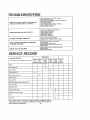
SERVICE
RECORD
SCHEDULE
SERVICE RECORD
t
..........
, W.,oo
VERY
200
IOURS
HoURStHOU"S
I .OURS .OURS!HOURS
i,,
Blades
Brake Adjustment
Check
Battery
Change
Check
Engine
X
011
X
Engine Oil Leve_
;lean Air Fitte="
X
,
Cheek Muffler
Clean A_r Screen and Engine Cooling
Clean
F}ns
X
Front Grill
Lubricate
i ......
X
1
X
Tractor
X
Replace Spark Ptugs
X
Replace Air Fiber Cart[}dge
X
Tires
FUe_ Filter
Seam, Roebuck
improvements
terms
X
and Co, reserves
without
imposing
hereto fore
manufactured,
the right
to make
any changes in design
any obligation
to install
the same upon
2B
or
its
i
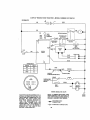
14 HP 38" RIDING YARD TRACTOR - MODEL NUMBER 917.254'710
SCHEMATIC
RED
RED
RED
WIRE
LOOP
WttlE
FUSE
0
B
_NmON
SWITCH
_P
i=_moli
' CIRCUIT
i,iii
I,I,G
Oil
START
I_
ORANGE
14YOLTS
^C(1,tNI [
LIGHTS
OFFAT
/,;0
WIRING
YOUR TRACTOR tS EQUIPPED WITH A
SPECIAL ALTERNATOR SYSTEM> THE
LIGHTS ARE NOT CONNECTED TO THE
BATTERY,
BUT HAVE THEIR OWN
ELECTRICAL SOURCE. BECAUSE OF
THIS,
THE BRIGHTNESS
OF THE
LIGI_ITS WILL CHANGE
WITH THE
ENGINE SPEED, AT IDLE SPEED THE
LIGHTS WiLL DIM, AS THE ENGINE IS
SPEEDED
UP, THE LIGHTS
WILL
BECOME THEIR BRIGHTEST.
INSULATED CLIPS
NOTE: IF WIRING INSULATED CLIPS
WERE REMOVED FOR SERVICING OF
UNIT. THEY SHOULD BE REPLACED TO
PROPERLY SECURE YOUR WIRING.
.,..,.,.il_. NON°R EMOVAB LE
CONNECTIONS
-"O'--
REMOVABLE CONNECTIONS
29
/-7
GROt_C
%°
N
3O
0
r_
I.U
r_
o
<o
__¢__
h.
0')
W
_r
,.I
ILl
o
Q
0
i
0
!u
o
€_
,I*
Ill
W
3t
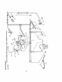
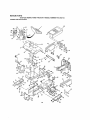
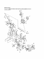
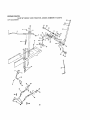
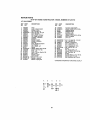
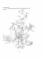
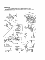
REPAIR PARTS
14 HP 38" RIDING YARD TRACTOR - MODEL NUMBER 917.254710
CHASSIS AND ENCLOSURES
G
30"
36
27
32
38
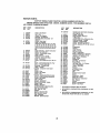
REPAIR PARTS
14 HP 38" RIDING YARD TRACTOR - MODEL NUMBER 917.254710
CHASSIS AND ENCLOSURES
KEY
NO.
PART
NO.
DESCRIPTION
i
3
,,4
5
£,
7
8
9
10
11
120039X
1055133(
I05529X
74780818
73680500
73680800
121642X
106202X
105801X
17490612
12
13
14
!6
17
19
20
21
22
23
24
25
26
27
28
29
30
31
32
33
35
36
37
38
39
40
41
42
43
44
45
46
47
48
49
19131312
STD523707
1055!1X
STD55It37
I21093X
121067X
19131614
1055093(
105531X
106020X
!21221X
6999R
5277J
106082X
121277X
121306X
105523X
121794X
1 I0828X
105525X
105465X
105464X
STD533707
165466X
110923X
3645J
105809X
108885X
110436X
105839X
1058383(
10575IX
105867X
109015X
109018X
A
_e.
B
Seat
Bracket-Pivot-Seat
Bolt-ShoulderS/t618
Bolt1/2-13x.1
Nut.,Lock S/16- 18
Nut+ Lock3/8 16
Fender
Rallector- Rear
Decal
Screw, Hex Washer Thd,, Rof1.,8/8 +
18 x 3/4
Washer13/32x13/t6xl"2Ga.
* Bolt, Hex 3/8 - 16x3/4
Strap-Fender
* Washer. Lock3!8
Cap * Spring
'.
Cempres+ien bpnng
Washer13/32 x l x14 Ga_
Bracket. Fender
Nut+ Push
Tank. Fuel
Cap- Fuel
Clamp +Hose
Line - Fuel
Pad- Spacer
Chassis Assembly
Drawbar
PaneI-Dash-L.H.
Cover.. Access
Panel- Dash- [7+H.
Bracket + Support - Dash
Footrest - L. H.
Footrest - RoHo
* Bolt, Carl. 3/8- 18x3/4
Pad, Footrest
Bracket- Clutch + Mover
Bushing
Decal. 5 Speed. 38"
Guard- Muffler
Grommet. Split
Receptacle
Retainer
Stud. I/4 Turn
Shield- Heat
Bracket- Pivot- L, H,
Bracket + Pivot. R. H.
c
s
KEY
NO,
D
E
_'l;+
@88
F.
G
DESCRIPTION
50
106013X012
Hood
51
52
53
54
55
56
57
58
61
62
63
64
65
68
67
68
69
70
71
72
73
74
75
76
77
78
79
80
81
2751R
108402X
!06910X
108067X
I05528X
I05806X
105568X
19131616
108403X
108410X
108091X
106090X
108909X
106003X
106004X
! 10897X
121144X
I08512X
!08513X
4900J
109!99X
Cu/i_lip
Washer
Pa/ Nuf
Grill
Decal
Decal- Slripe
Washer13/32xlx16Ga+
Panel - Side - R. H+
Panel. Side - L, H
Hinge. [7+Ho
Hinge + L. H,
Screw - Special
Lens - R, H,
Lens - L. H.
Bezel - Headlight
Belt - Shoulder
Bracket. Pivot - It+ H.
Bracket. Pivot+L.H_
Decal + Clutch/Brake
Decal - Drive Belt
89
90
9I
92
93
94
95
98
97
19171912
121247X
121251X
121246X
121249X
72170410
121250X
121248X
73900400
* Bolt-Hex3/8.16x
1
Stem., Tank, Fuel
StrapAssembly- Grill
Washer- Lock, Ext. Tooth 3/8
Decal. S!ripe, Side Panel- L. H+
Decal - Stripe, Side Panel- It+ H,
Decal, Caution
Bolt, Hex Washer ThdoRoll.378.18
xl
84 17490608
Screw, Hex Washer Thd. Roll. 3/8.
16x 1/2
68 $77J551150 " Washer- Lock I/2
STD523710
8710J
119350X
11050600
108813X
106814X
106974X
17490816
Washer17/32xl-3/16x12Ga,,
Pan Seat
Strip Foam
Bracket, Switch Mount
Spacer Split
Bo/t Cam I/4.20x
1 I/4
Compression Spring
uushtng, Snap
Nut, Range, Lock I/4 +20
"STANDARDHARDWARE--PURCHASE LOCALLY
H
J
K
_62
@89
_
PART
NO+
®7
77
33
L
N
P
Q
@7
R
REPAIR PARTS
14 HP 38" RIDING YARD TRACTOR - MODEL NUMBER 917.254710
DRWE
13
76
/
7O
_6B
36
57
57
g9
,,
//
-- OPTIONAL
EQLIIPMENT--
SPARK ARRESTER
KIT
]
REPAIR
PARTS
14 HP 38" RIDING YARD TRACTOR - MODEl. NUMBER 917.254710
DRIVE
KEY
NO,
f
2
4
PART
NO.
t05703X
12000028
121319X
5 106963X
8 110658X
9
t0
11
12
13
!6
17
18
19
20
21
22
23
24
108373X
100229L
STD522507
STD651125
8545,1
t10902X
120302X
275tR
105933X
106699X
!0670tX
19151216
STD561210
17490612
25
26
27
28
29
30
31
32
33
34
35
I05730X
STD523707
19131312
73680600
8883R
109037X
STD5718t0
121749X
I05918X
STD580025
121440X
36
121441X
37
38
39
40
41
104777X
109070)(
4470J
4859J
STD523727
42
43
44
45
46
47
46
49
I0573tX
1004O7O0
74770720
I09366X
4921H
109370X
1O8190)(
190.91210
DESCRtPTION
KEY
NO,
Pulley, Transaxle (Driven)
_ing, Retainer
......
! ransaxle, 5 Speea, t-oote Mooel
/voo4160.61 (see pages 42 and 43
for parts breakdown)
Duct, Air Intake
Engine, Briggs and Straiten Model
No.. 400707, Type No° I507-01
Muffler
TubeAssembly.Exhaust
* Bolt, Hex t/4.20_
3/4
* Washer, Lock 1/4
Gasket
Valve,Drain,
Oil
V-Belt, Drive
Ctip
Knob
Rod, Shifter
Washer- $haft Plate
WashertS/32x3/4xf6Ga.
"Pin, Colterl/8
x l
Screw, Hex Washer Hd Thdo Roll,
3/8- 16 x 3/4
Keeper, Belt, Engine
° Bolt, He_ 3/8- I6 x 3/4
Washer 13/32x 13/16x 12 Ga.
Nut, Lock 3/8.16
Cover, Pedal
Shaft, Foot Pedal
" Pin, Rol13/16x f
Washer25/32x
1-t/4 x 16 Ca,
Arm, Brake
" Key, Wood_ff Na_ 9
Guide, Belt, Lower, Eng. Pulley L
H.
Guide, Belt, Lower, Eng. Pulley R.
H.
Retainer, Belt Chassis
Keeper, Belt
Spacer
Idler, Flat
*Bolt, Hex3/8.16x2-3/4
Pulley, Engine
Washer, Lock 7/16
*Bolt, Hex 7/18- 20 x 1_1/4
Keeper, Belt L. H.
Retainer Spring
Strap, Locater
Clamp
Washer9/32 x 3/4 x 10 Ca..
PART
NO,
DESCRIPTION
51
62
53
54
55
56
57
68
59
60
61
62
STD523107
73680600
STD523727
I05842X
1O9167)(
106t57X
76020412
105844X
110437X
71673
106888X
STD551037
' Bolt, He_ 5/16- !8x3/4
Nut, Lock 5/16- 18
" Bolt, Hex 3/8.16x 2-3/4
Strap, Torque
Bracket, Transaxle
Plate, Strap, Torque
Pin, Cotter t/8 x 3/4
Rod, Brake, Park
Red, Brake
Cap
• Spring, Red, Brake
Washer 13/32x 13/16x 16 Ca.
64
65
66
67
68
69
70
71
72
73
74
76
77
78
79
80
8!
82
83
84
85
86
87
68
STD541237
105724X
STD533707
f08298X
105707X
106499X
STD623715
110812X
12000039
105709X
105710X
121488X
17080408
59192
65139
106268X
106108X
109502X
121749X
12000001
I04757X
STD580105
t09369X
17490624
89
17490512
" Nut, Hex, Jam3/8 .16
Bracket, Clutch
• Bolt, Cart. 3/8 - 16x3/4
Pulley, Idler
Bellorank Assembly
Retainer, Be#
" Bolt, Hex3/816x 1-1/2
Washer, Hardened
xsss Ring
Spring, Return, Clutch
Link, Clutch
Control, Throttle
Screw, Hex Thd.. Cut. 1/4- 20x 1/2
Cap, Valve
Stem, Valve
7ire, Rear18 x 9.60 x 6
Rim, 8"
Spacer, Split
Washer25/32 x 1-1/4 x 16 Ca.
EoRipg
Cap, Hub, Rear
" Key, Square 3/16x2
Keeper, Belt, R, H.
Boll, Hex Washer Thd. Roll. 3/8 - 16
x 1.1/2
Screw, Hex Washer Thd. Roll. 5/16
• !8x3/4
* Bolt, Hex 3/8.16
x I
Bearing
Bolt, Hex 1/4.26x3/4
Washer13/32x1-1/4xt2Ga
Plate, Red, Shift
Spring, Torsion
Tube (Not fumishedwith tractor)
Spring, Brake Return
Spark Arrestor Kit
Nut Kepso 3/8- 16
Washer Lock Tooth 3/8
90 STD523710
91 105706X
92 71040412
93 19132012
94 I06919X
95 105700X
97 7152J
98 110422X
99 674A380
IOOSTD541437
10tSTD551237
"STANDARD HARDWARE-PURCHASE
A
B
C
D
E
F
_26
(_66
G
_
"sT
@ 27
28
ss _
K
28
L
ss
M
eo
,q
9o
28 @g3
928
sz
J
LOCALL Y
35
88
'_,_ lol
REPAIR PARTS
'14 HP 38" RIDING YARD TRACTORSTEERING
MODEL NUMBER 917.254710
ASSEMBLY
,o,-,.--1
_f2
13
_4
20"_'_ D
"_...._I
7
_,o
\
83
38
27
3
36
REPAIR PARTS
14 HP 38" RIDING YARD TRACTOR - MODEL NUMBER 917.254710
STEERING
KEY
NO.
ASSEMBLY
PART
NO.
1
2
3
4
5
6
7
8
9
10
11
106810X
100710L
73940800
100712K
I00713N
1007t1L
106015X
120028X
120003X011
1098t6X
17490608
12
13
14
15
16
17
18
121749X
108705X
2882J
71208
109432X
108685X
17490612
19 108683X
20 12000029
2I 6268H
22 108684X
23 106126X
24 1055t8X
25 74180512
26
27
28
29
30
31
-32
34
35
36
38
39
40
41
A
73680500
108263)(012
73680600
STD523120
121236X
106001X
STD523707
19111216
121232
121526
11050600
72110608
105669X
105663X
B
DESCRIPTION
KEY
NO,
Decal - Cap Steering Wheel
Insert. Steering Wheel
* Nut. Top Lock 1/2-20 UNF
Washer
,
Wheel-Steering
• Adapter- Ste_rtng Wheel
Sleeve - Steering
Dash
Dash Plate
NsYcliner Snap-In
row- Hex Washer Thd Roi13/8 16x 1/2
Washer 26/32 x 1-1/4 x 166A
Shaft- Steering
Pin.Drive
Bushing
;
Bracket-Steering
Gear- Pinion
Screw- Hex Washer Thd. Roll. 3/8 16x3/4
Rod- Steering
Ktlp Ring
Bearing. Thrust
Gear., Sector
Key- Woodruff
Dash - Lower
Screw. Crown Truss Hdo 6/16 - 18 x
3/4
Nut - Lock 5/16 - t8
Saddle
Nut-Lock3/818
Bolt. Hex5/16.18x2
Spacer
Support Plate -Battery
Bolt-Hex378-16x3/4
Washer11/32 x 3/4 x 166A
Cap Spindle
Control- Choke
Washer. Lock, IntJExt. Tooth 3/8
Bolt- Carriage
Axle - Front
Support - Saddle - Rear
C
D
E
F
G
PART
NO,
42
43
45
46
47
74761060
I06664X
110438X
73901000
17490508
48
49
50
51
52
53
54
55
56
67
58
59
60
61
62
64
65
66
67
68
69
70
7I
72
73
74
75
76
77
78
79
80
63
84
85
I06656X
I05654X
121748X
121321X
STD551131
STD541131
3366R
t06727X
STD551137
STD641137
1654J
17431008
104757X
2751R
STD641037
59192
65139
278H
9040H
106732X
106222X
101930X
108456X
69904
72110622
121235X
19131416
74580
STD512507
19091216
73510400
19272016
6320R
19111216
121232X
DESCRIPTION
Bolt - Flex 5/8.11 x 3-3/4
Support. Saddle - Front
Spacer Bearing - Front Axle
Nut - Lock - Flange 5/8.11
Screw- Hex Washer Thd, Roll. 5/16
- I8x 1/2
SwPaindfe- L. H,
fndle - R. N
sher 25/32 x t -5/8 x I6 Ga°
Rod - T_e
" Washer- Lock 5/16
* Nut - Flex 6/16- 24
Bearing
Link- Drag
* Washer - Lock 3/8
" Nut. I.fe_:3/8 - 24
Bushing - Steering
Screw. Hex No. 10.16x
1/2
C_ip ,, Hub * Front
• Fuel Line
* Nut . Hex 3/8 - 16
Cap- Valve
Stem - Valve
Fitting- Grease
Bearing
Rim - 6" Front
Tire., Front
Washer- Hardened
Decal. Instructions; Operating
Tube - Tire. Front
Bolt. Carriage Flex 3/8- 16 x 2.3/4
SWPa
acer
sher 13/32 x 7/8 x 16 Ga.
Spacer
* Screw _ Pan Head 1/4.20 x 3/4
Washer 13/32 x 3/4 x 16 Ga.
Nut, Keps 1/4 NC
Washer27/32 x 1 I/4 x 16 Gao
Clip, Insulated
Washer 11/32 x 3/4 x I8 Ga,
Cap Spindle
*STANDA RD HARDWARE--PURCHASE
H
J
K
--
L
2e
28
28
_s6 82
_ _s
@ 56
_e2
"t"I
,_38
_ 28
_78 79
_
LOCALL Y
REPAIR PARTS
14 HP 38" RIDING YARD TRACTOR
-MODEL
NUMBER
917.254710
LIFT ADJUSTMENT
t4
A
17
I
48
44--_
!1
35
36
/
33
f
/
39
8
40
38
REPAIR PARTS
14 HP 38" RIDING YARD TRACTOR - MODEL NUMBER 917.254710
LIFT ADJUSTMENT
KEY
NO.
1
2
3
4
5
6
7
8
9
10
11
12
13
14
15
16
17
t8
19
20
21
22
23
24
25
26
27
PART
NO.
106833X
110924X
106498X
73680600
STD523707
10645IX
108387X
76020412
106308X
109728X
108236X
106444X
1200037
100734K
110807X
110729X
2876H
STD551037
17021008
121000X
121002X
t21006X
105723X
109413X
STD523715
STD551137
110739X
DESCRIPTION
KEY
NO.
Knob
Lever_MowerClutch
Bracket - Pivot
Nut-lock3/816
° Boft-Hex3/8,16x3/4
Bolt _ Shoulder
Rod..Clutch.
Pdmary
Pin-Cotterl/8x3/4
Trunnlon-LtitLower
Bellcrank
Bracket - Switch
Bracket. Bel/crank
KtipRing
Knob, Depth Adjustment
Nut.Special
Rod - Adjust - Lift
Spring
* Washer13,32xS/Sx
16Ga.,
Screw-HaxHd,
Tap.
Shaft*Lift
Lever- Ltft (Inc, Key No. 22)
Rod-Lever
Plunger. Lever
Grip- Handle
° Boi13/8.16x
1.1/2
* Washer- Lock 3/8
Washer-Spring3/8
PART
NO.
28 110810X
29 19151216
30 9135R
31 4939M
32 110447X
33 4921H
34 19171516
35 110448X
36 110029X
37
38
39
40
41
42
43
44
45
46
47
48
49
50
52
STD533707
STD541237
105864X
121599X
106848X
121598X
STD541050
56606
76020308
19131410
73980600
12000022
19292016
73360700
73710700
DESCRIPTION
Trunnion _ Stop Depth
Washer 15/32 x 3/4 x 16 Ga.
Retainer Spring
Retainer Spring
Trunnion - Lift
Retainer Spring
Washer 17/32 x 5/10 x 16 Ga
Link _ Lift Adjust
Link ,. Lift
* Bolt. Carriage 3/8.16 x 3/4
* Nut-Jam3,8t6
Bracket - Suspension
Arm - Suspention - L.H.
Bolt - Shoulder 3'8 - 16
Arm. Suspension - R FL
* Nut- Hex Fin I/2.13
Spring
- Coffer 3/32 x !/2
Washer 13,32x 7A_X 10 Ga,
Nut .. Lock 3/8 - 16
E-Ring
Washer29/32 x 1 1/4 x 16 Ga,,
Nut Hex Jam 7/16 -20
Not Crownlock Jam 7/16-20
'STANDARDHARDWAR_-PURCHASELOCALLY
A
B
C
D
E
19
_5
_4
_27
_p 47
39
REPAIR PARTS
14 HP 38" RIDING YARD TRACTOR - MODEL NUMBER 917.2547'10
38" MOWER
43
4_5
45
25
6
CC
_
C
58
J
40
REPAIR PARTS
14 HP 38" RIDING YARD TRACTOR - MODEL NUMBER 917.254710
38" MOWER
KEY
NO.
PART
NO.
I
2
3
4
5
6
7
8
9
10
11
12
13
14
15
16
17
18
19
20
21
22
23
24
25
26
27
108085X
t21259X
8417J
73680600
19111216
72140505
105896X
110452X
106734X
t06735X
106_36X
105814X
185304X
105662)(
105744X
4921H
105872X
109835X
STD523707
73680500
109598X
109597)(
STD533107
37t3J
109503X
109504X
. _.
28
29
30
31
32
33
34
35
36
37
121317X
STD523720
108832X
76020308
121316X
106902X
102669X
12t687X
100668L
17490612
DESCRIPTION
KEY
NO.
PART
NO,
36 t7490620
V.Belt
Housing
Runner, R. H..
Nut, Lock 3/8- 18
Washer11/32x3/4x16Ga,
Bolt, Cart. 5/16 - 18 x 5/8
Bracket, Deflector
Push Nut
Spring, Deflector
Rod, Hinge
Deflector, Shield
Decal
Cap
Link, Parallel
Pin, Hinge, Front
Spring, Retainer
Step, Link
Ptn; Hinge, Rear
* Bott3/8- 16x3/4
Nut, LoCk 5/16 - 18
Bracket, Lift, R. H.
Bracket, Lift, L, H.
* Bolt, Cart. 5/16- 18x3/4
Instruction, Caulion Decal
Support Arm
Slop, Deck, Front
Decal, Safely Standard- Not
Serviced
Guide, Belt
* Boft3/8.. 16x2
Arm, Idler
Pin Cotter
Pulley, Idler
Spacer, Retainer
Keeper, Belt
Jackshaft A_sembly
Plate, Support, Jackshaft
Screw, Hex Washer Hd_ 3/8 - I6 x
374
39
40
41
42
43
44
45
46
47
48
49
5O
51
52
53
54
55
56
57
58
59
60
61
62
63
64
65
68
67
68
69
73
74
75
76
77
121263;4
19132012
STD551137
STD632715
I08250X
I08235X
4921H
STD560907
109892X
76020616
108247X
STD533707
121343X
108243X
I08241X
I05857X
I08673X
106578X
I06463X
108249X
106456)(
t00672K
100673L
106513)(
19111018
74760888
7631J
19131614
72140610
3713T
122314X
74760412
tO9893X
73680400
110445)(
72110506
DESCRIPTION
Screw, Hex Washer lid, 3/8 - 16 x
1-1/4
Blade, 38"
Washer13/32 x l-1/4 x12 Ga.
" Washer, Lock3/8
* Bolt, Hex 3/8 - 24x 1-1/2 Gr. 5
Spring, Extension
Rod, Clutch, Mower
Spring, Retainer
" Pin, Cotter 3/32 x 3/4
Rock Shaft Assembly
Pin, Cotter3/16 x I
Rod, Brake, Primary
* Bolt, Can'. 3/8- 16x3/4
Decal Warning
Bracket, Pivot, R_H.
Bracket, Pivot, L..H.
Bracket, Suspension, Rear, R. H
Bracket, Suspension, Rear, L. H.
Brake Assembly
Rod, Brake, Secondary, L. H.
Rod, Brake, Secondary, RoH.
Bracket, Brake, Pivot
Spacer, Brake
Bracket, Support
Washer, Wear
Washer I I/32 x 5/8 >_16 GaD
Bolt3/816x5-1/4
Runner, L. H.
Washer 13/32x I x 14 Ga.
Boil, Carr. 3/8 - 16x 1.1/4
eaf,Warning
acer, 5pfit
olt, Hex 1/4 - 20 x 3/4
Washer, Special
Nut I/4 - 20
Plate Support Lo H. Jackshaft
Bolt Ro Hd Sq Nk 5/16 - 18 x 3/4
MowerAssembly Coml_ete
1222t5X
*STANDARD HARDWARE.-PURCHASE LOCALLY
t
A
B
_'23
_s
C
23
_2o
E
5O
Q4
G
6
H
J
K
L
M
N
P
64
_2o_
4
20
Q
_20
4!
®4
_74
.
REPAIR
PARTS
14 HP 38" RIDING YARD TRACTOR - MODEL NUMBER 917.254710
TRANSAXLE FOOTE - MODEL NUMBER 4150-61
TRANSAXLE
5,
16
4o
42
53
/
_o39
54
53
/
57
REPAIR PARTS
14 |'IP 38" RIDING YARD TRACTOR - MODEL NUMBER 917.254710
TRANSAXLE FOO'fE - MODEL NUMBER 4150-61
TRANSAXLE
KEY
NO.
PART
NO.
I
2
3
4
5
6
7
8
I06845X
2276J
121118X
68003
105904X
1O5905)(
2287J
2233J
2232J
2231J
2230J
2229J
2228J
2227J
2226J
105906X
9 6725J
10 2228J
11 2257J
12 106846X
13
14
15
16
17
18
19
20
21
22
23
24
25
26
27
28
29
30
31
32
33
I06095X
105909_
I05910X
105911X
105912X
105913X
I05914X
2242J
106096X
2244J
105916X
105917X
110070X
109253X
108978X
I09254X
108980X
120406X
108445X
105925X
108981X
34 120998X
35 3413J
36 105928X
37 t06605X
DESCRIPTION
KEY
NO.
Housing, upper
Screw, Tapping, 1/4-20 x 1.31Lg.
Screw, Tapping, I/4-20 x.875 Lg.
Ball, Detent
Spring, Detent
Screw, Set
Ring, Retainer
Washer, Plain, .632 x Io00 x .020
Washer, Plain, .632 x 1.00 x °026
Washer, Plain, .632 x 1_00 x _031
Washer, Plain, _632 x 1_00 x _036
Washer, Plain, .632 x 100 x .041
Washer, Plain,° 632 x 1.00x .048
Washer, Plain,. 632x 1_00x_050
Washer, Plain, 632x 1.00 x.060
Washer, Plain, ,632 x 1.00 x_082
O-Ring
Washer, Plain, .832 x 1.O0x .046
Key, Woodruff, No, 9
Assembly, Kit, Input Shaft (Inc'so
Key No so 7,8,9, tt, 12, I3,14,71, and
2 Needle Bearings)
Pinion Bevel 14T
Ring, Retaining
Chain, 24 Pitches
Bearing, Flange
Gear, Spur, f4T
ColfarClutch
KeeY,Clutch
y, Woodruff, No. 3
Shaft, Intermediate
Key, Woodruff, No. 61
ing, Retaining
Sprocket, 18T
_s_aacer
ah Spur, 40T
cer
ear, Spur, 35T
Gear, Spur, 25T
Gear, Spur, 22T
Gear, Spur, t9T
Washer, Plain, .640 x 137x .081
Assembly, Gear° Combo., 12T &
35T
Shaft, Idler
Washer, Plain, ,83 x 1o00 x .01
rOCket, 9T
at', Bevel, 42T
38
PART
NO,
39
40
41
42
43
44
45
46
47
48
49
50
51
52
53
54
55
56
57
58
59
60
61
62
63
64
65
66
67
68
69
70
I08983X
105930X
10593tX
105932X
3417J
I06097X
2264J
I06098X
2265J
106586X
t06587X
106588X
2263J
108727X
106151X
106589X
120408X
I0593FX
106152
2226J
2272J
2264J
110080X
120409X
105941X
t10071X
120952X
106592_
110083X
I09002X
108987X
109975X
120997X
7294J
108989X
120953X
120954X
_08992X
120951X
120956X
120955X
108996X
73810500
120993X
106596X
7I
72
120415
120416X
DESCRIPTION
Washer, Plain, .758 x 1_12 x .010
Washer, Plain, 758 x 1.12 x.015
Washer, Plain, 758 x 1.12 x .020
Washer, Plain, 758x 1o12X 025
Washer, Plain, 758 x 1,25 x 020
Washer, Plain, 758 x 1.25 x .025
Washer, Plain, 758 x 1.25 x ,03 I
Washer, Plain, 758 _r 1.25x .035
Washer, Plain, 758x 1.25x ,040
Washer, Plain, ..758 x t. 25 x .045
Washer, Plain, .758x 1.25x 050
Washer, Plain, _758 x 1 25 x.055
Washer, Plain, _758 x 1.25 x .062
V-Ring
Gear, Spur, !5T
Gear, Spur, 25T
Gear, Spur, 28T
Gear, Spur, 31T
Shaft, Drive
Washer, Plain, °640 x trO0 X .060
Seal, Felt
Washer, Plain, .758 x 1.25 x o031
Axle, L Ft.
Gear, Miter, 15T
Ring, Retaining
Gear, Spur, 32T
Shaft, Cross
Gear, Miter, 15T
Axle, R. H.
Assembly, Shifter
Cap, Support
Housing, lower
Puck, Friction
Disc, Brake
Spacer
Jaw, Brake
Pin, Dowel
Lever, Actuating
Puck, Friction
Bracket, Anti-Rotation
Screw, Tapping, 5/!6-18 x 250 long
Washer, Plain .321 x 1.00 x .055
Nut, Lock, 5/I6-24 (Nylon insert)
Washer, Plain .34 x .8 t x 06
Screw, Tapping, 5/16- 16 x 1.44
Long
Washer, Plain, 63 x 1 38 x. 05
Grease
*USE IN VARIOUS COMBINATIONS TO MAINTAIN
PROPER CLEARANCE.
+ NOT SOLD SEPARATELY--ORDER
43
KEY NO_ 12
REPAIR PARTS
14 HP 38" RIDING YARD TRACTOR - MODEL NUMBER 917,254710
ENGINE BRIGGS AND STRATTON - MODEL NUMBER 400707, TYPE NUMBER t507-01
CYLINDER,CRANKSHAFT,
ANDENGINEBASEGROUP
4
3 7
82
4
54_
44
REPAIR PARTS
14 HP 38" RIDING YARD "[RACTOR - MODEL NUMBER 917.254710
ENGINE BRIGGS AND STRATTON - MODEL NUMBER 400707, TYPE NUMBER '1507-01
CYLINDER,
KEY
NO.
PART
NO.
1
4
5
6
7
8
9
10
90576
27803
92791
222892
93722
93394
222912
93777
11
12
13
14
15
t6
17
18
19
93158
491247
93862
270981
222860
261463
210940
212462
93111
20
93113
21
22
93686
92290
23 393415
24 260924
25 394959
25 394960
25 394961
25 394962
26 394955
28
26
26
27
394958
394957
394958
299691
27391286
28 394348
29 222773
30 393270
31
32
33
34
35
36
37
92909
220863
291675
91084
393552
270983
271142
37 271188
37
CRANKSHAFT,
27118g
AND ENGINE BASE GROUP
DESCRIPTION
KEY
NO.
PART
NO.
Nut- Hex 8 o 32
• Gasket- Valve Cover
Washer. Lock, shekepreof
Cover- Breatber Cylinder No_ 2
Terminal- Spade
Screw* Sam
Baffle-Air
Screw- Hex Head (Back Plate to
Cyfinder)
Screw- Sam
Housing. Blower
Screw- Crankcase Cover Mtg, Sere
• Gasket- Crankcase
Cover Plate. Crankcase
+Seat - Inlake Valve (Standard)
+Seat * Exhaust Valve (Standard)
Head - Cylinder No. 2
Screw - Cylinder Head (I- 15/16"
Long)
.
Screw - Cylinder Head (2-5/16
Long)
Screw- He_"Head (10 _ 32 x 5/8)
Washer- Lock (Noo 10 x 1/16x 3/
_it)
Slinger Assembly
Lock - Piston Pin
Ring Set - Piston _Standerd)
Ring Set. Piston {,010" O.So)
Ring Set - Piston (o020_ OoS,)
Ring Set - Piston(.030
O.S,)
Piston Assembly (Standard) (Inc.
KeyNos. 24 & 25)
Piston Assembly (010". O.S.)
Piston Assembly (.020. 0 SJ
Piston Assembly (,030 O,S,)
Pin Assem b¥- Piston (Standard)
(lnc, t_eytvo. 24)
.
Pin Assembly - Piston {,005 O,S.)
Gear. Governor
Washer- Thrust
Rod Assembly- Connecting (In_
KNeyNos. 31 & 32)
OTE: FOR CONNECTING ROD
WITH o020" UNDERSIZE
CRANKPIN BQRE, ORDER NO_
393714
Screw- Connecting Rod
Washer 1/4 x 5/8 x t732
Seal. Oil
Plug- Oil Drain
Base Assembly - Crankcase
38
39
40
41
42
43
44
45
46
47
48
49
50
51
52
53
54
Gasket
Gasket
thick)
• Gasket
thick)
" Gasket
83 93496
84 223890
88 221536
thick)
222698
93585
94296
491287
261560
262332
491530
220863
394501
271157
93469
212968
222875
280224
271170
394020
394394
85 390419
56 261528
57 231445
59 26828
60 292260
61 93630
62 221898
63 65906
64 261368
65 393382
66 261961
67 394941
68 230318
69 394539
70
71
72
73
74
75
76
77
78
79
80
81
82
_ Cyllnder Flead No_2
.
- Crankcase Cover (1/64
* Crankcase
DESCRIPTION
66538
89838
280225
394358
212461
270984
491304
399265
39 t086
391115
299146
93053
393370
+
Key. Flywheel
Screw - Hex Head Sam
Retatner- E-Ring
Foam Seal. Governor Shaft
Upper Bushing- Governor
LowerBUShing_ Governor
Crank. Governor
Washer. Governor Crank (Inside)
Gasket Set
Seal,. Filler Tube
Screw - Hex Head
Gear. Cam
Clamp - Oil Filler
Tube _ Oil Filler
Seal - Oil FitterCap
Cap and Dipstick -Oii Filler
Dipstick and Tube Assembly (Inc.
Key Noa. 47, 48, 50, 51, 52 & 53)
Valve * Exhaust
Valve. Intake
Gear- Timing
Spring - Exhaust Valve
Rolocoil- Exhaust Valve
Retainer- Exhaust Valve Rotocofl
Retainer. Intake Valve
Spring - Intake Valve
Tappet- Valve
Crankshaft
NOTE; ORDER NO, 94196
FOR TIMING GEAR RETAINING
DEVICE
Guide. Exhaust Valve (Only)
NOTE: NO, 231218 GUIDE INTAKE (BRASS)
.....
Cylinder Assembly (lnc, t_ey rqo, __)
Connector- Impulse Pump
Plug - Spark (Resistor)Champion
Rj- 12 or equivalent
Elbow - Spark Plug
Wrench - Spark Plug
Tube - Breather
'
Filter- Fuel (ln Fuel Line to Tank)
Head - CyfiriderNo. 1
Gasket* Cyltnder Head No, I
Back Plata Assembly
Bearing. Cylinder
Seal. Oil
Wire - Ground
Line _Fuel(Inc. Key Noo81)
Clamp. f ueI Lfne
Breather Assembly No, 1
Screw- Hex Head,
Bracket. Choke Cable
Clamp - Casing
Cover (,005"
* INCLUDED
- Crankcase Cover ('.609"
iN (":_SKET SET NO. 394501
+ SPECIAL TOOLS REQUIRED
45
TO INSTALL
REPAIR PARTS
14 HP 38" RIDING YARD TRACTOR - MODEL NUMBER 917.254710
ENGINE BRIGGS AND STRATTON - MODEL NUMBER 400707, TYPE NUMBER 1507-01
A;R CLEANER
- CARBURETOR
GROUP
76
73
75
,61
38
39
34
66
)..._--23
_-----64
6O
57
55
56
67
69
4!
46
REPAIR PARTS
14 HP 38" RIDING YARD TRACTOR ,, MODEL NUMBER 917.2547t0
ENGINE BRIGGS AND SI'RAI'TON - MODEL NUMBER 400707, TYPE NUMBER 1507-01
AIR CLEANER
KEY
NO.
PART
NO,
- CARBURETOR
GROUP
DESCRIPTION
KEY
NO.
PART
NO,
40 393815
1
2
3
4
5
212706
94289
223579
271271
224039
6
7
8
94166
398826
491427
9
t0
11
12
14
15
16
17
399327
271411
93499
223534
392673
271609
298514
94152
18 491531
19 231209
20 223370
21 271412
22
23
24
25
26
27
28
29
30
31
32
33
34
35
36
37
38
39
93897
93971
280818
270884
93208
93970
261587
280319
213290
93949
262351
491297
92278
222289
261563
93853
261588
491282
Knob - Air Cleaner
Nut-Hex
Cover- Air Cteaner
Element. Air Cleaner
Mounting Strap Assembly - Air
Cleaner
"
Screw= Hex Head
Body - Air Cleaner
Carburetor Assembly(Inc. Key Nos°
9, I0. II, 12, 13, 14, 15, 18, 17, 18,
19,20, 42, 43, 44, 45, 46, 47, 48, 49,
50, 51, 52, 53, 54, 55, 56, 57, 62 &
63)
BodyAssembly, - UpperCarburetor
Gasket - Air Cleaner
Screw. Throttle and Choke
Valve.Choke
Shaft and Lever- Choke
+Gasket- Carburefor Body
Float. Carburetor
Screw- Flex Head Sere (10 - 32 x 3/
4_o
dy - Lower Carburetor (lnco Key
Nos. 1I, 19, 20, 45 & 46)
Brushing - Throttle Shaft
Valve. Throttle
* Gasket- Carburetor and lntake
Elbow
Screw-Sam
Screw _Flex Head
Crank. Bell
* Gasket - Intake Manifold Mounting
Screw- Intake Manitold Mounllng
Screw-HexHead
Link-Throttle
Spacer-Carburetor
ManifofdAssemblyIntake
Screw- Sere
Spring- Governor
LeverA_embly-Govemor(lnco
Key &los. 34, 35 & 37)
Nut. Hex (tO- 24)
Washer
Spring - Governor Idle
Bolt, GovemorLever
Link. Governor
Bracket- SpeedControl
41
42
43
44
45
46
47
48
93053
397882
280474
491538
392672
271013
26157
91920
49
50
51
52
53
54
55
56
57
58
59
270988
261358
221377
261395
223688
93829
271025
270989
280197
394501
394019
60
6t
62
63
64
65
66
67
68
69
70
71
72
73
74
75
76
223472
223714
230896
394681
271013
231339
490207
282375
223893
221535
93498
393397
491539
94298
223882
262337
94297
"
INCLUDED
+ INCLUDED
491539
x
47
DESCR|PT]ON
lmputse Line and Clamp Assembly
(Inc. Key No, 41)
Clamp - Fuel Line
.
Plug and Seal, Solenoid
O.Ring Seal
+Valve Assembly- Carburetor Idle
Shaft and Lever- Throttle
+Washer.. Choke Shaft
Spring - Throttle Adjustment
crew. Machine Fill. Hdo (8 - 32 x 5/
8)
xDiaphragm
xSpring
xCap . Spring
xSpring - Pump
Cover - Diapnragm
Screw- DiaphragmDamping
xGasket - Carburetor Pump
xDiaphregm - Damping
Body. Pump
Gasket Sat
Cartridge - Air Cleaner
Plug. Welch
Cartridge Plate - Air Cleaner
+Pin - Float Hinge
+Valve - Fuel Inlet
Washer"
Jet Needle Valve
Crank - Bell
Link
Bracket-Control
Cable
Clamp
Screw Hex - Head
Repair Kit. Pump
Overhaul Kit - Carburetor
Nut. Square
Washer
Spring - Compression
raw- Pan Head
IN GASKET SET NO 394501
IN CARBURETOR
OVERHAUL
KIT NO.
iNCLUDED IN CARBURETOR OVERHAUL K_T NO,.
491539 AND PUMP REPAIR KIT NO. 393397
REPAIR PARTS
14 HP 38" RIDING YARD TRACTOR _ MODEL NUMBER 917.254710
ENGINE AND
BRIGGS
AND STRATTON . MODEL NUMBER 400707, TYPE NUMBER 1507-01
ALTERNATOR
STARTER MOTOR GROUP
1
1-1
2
Q--,
38
48
REPAIR PARTS
14 HP 38" RIDING YARD TRACTOR - MODEL NUMBER 917.254710
ENGINE BRtGGS AND STRATTON * MODEL NUMBER 400707, TYPE NUMBER 1507-01
ALTERNATOR
KEY
NO.
PART
NO.
f
2
3
4
5
6
94326
222673
230674
2225I 1
223726
491180
8
9
393458
393474
10 93621
11 391362
12
19203
13 394891
I4 93381
15 221798
16 394970
17 93163
18 222849
19 222847
AND STARTER MOTOR GROUP
DESCRIPTION
KEY
NOr
PART
NO.
Screw - Sern
Screen - Flush Rotating
Nut = Hex
.
Washer * Spring
Retainer- Fan
FMlywheeland Ring Gear Assembly agneto
Connector Assembly (Dual Cieruit)
Stator. Alternator (Dual C#cuit)
(Inc. Key No. 8)
Screw- Sem
Gear- Flywheel Ring (Includes
Mounting Parts)
Puller- hTywheel (Optional
Accessory)
.
.
Armature Group (Inc. Key Ivoso 15,
16 & 38)
Screw- Armature Mounting Sere
Terminal. Ignition Cable
Trigger Coil Assembly - Magnatron
Ignilion
Screw- Sem
Cover- Air Guide
Shleld. Cyfinder
20 222846
21 222848
24 394808
25 395537
26
27
28
29
30
31
32
395538
393825
94003
390837
394860
90366
91162
33
34
35
36
280104
398003
94192
393254
37 396865
38 394988
39 280815
40 93535
4g
DESCRIPTION
Shield. Cylinder
Cover - Air Guide
Motor- Starting (lnc_ Key Noso 25,
26, 27, 28, 29, 30, 33, 34, 35, 36
&37)
Commutator.End Cap Assembl_
Starter (lnc. t_ey r_o_26)
Brush Set
Housing Assembly
Thru Bolt
Armature Assembly (Motor)
Drive End Cap t_ssernbly . Staffer
LocKwasher
Screw. Hex Head (%/16 - 18 x 1-I/
_ear-
Starter
Clutch Assembly.
Starte r
Roll Pin
Pinion Spring Kit (Inc. Key Nos. 33
&35)
Starter Drive Group (Inc. Key Nos.
33, 34, 35 & 36)
Armature Assembly
Fan o Fly_'heel
Screw- Sern
Attachments
ThatAddtotheUsefulness
ofYourCraftsman
YardTractor
Sears oilers a wide varietyof aitachmenls that fit your tractor, Many el these eretistad be_owwilhbrief explanaUons
of how they can help you Thta
Iistwas current at the timeo1publ.
icat_n:however, it may coange +nrufure years -- more attachments may be added,changes(intruding changes
In the stocknumber) may be maclein mesa attachrnan_,or somemayno longer be ava_at_e+
i_ost of thesealtachmentsdo not requlre additionalhilches or conversionkits ([hosethat de are tndicaled)and are designedtot easy attachingand
detaching.You may orderthese attachmentsat mesl Sears relait stores,calalog Palesollices, and throughI.hecatalogo
PERMANEX BAGGER letayou collectgrassclippingsand leaveslora healthierneatar4oekinglawn.Two Permenex containershold 3O.gallon
p_as_ic
bags Stocknumber71,.24940
LAWNSWEEPERStet youcollectgrass clpplngs and loaves
71-24030
7f o24032
304n.
32-1n.
&0 cu. It.
10.0cu, &
7f-24033 High-Pedormanca
7f.24038 Hlgl_Pedormar'¢._
32 in.
384n.
ti.5 cu, It.
I25 ou. It.
LAWNVACS for powertutco_c_one ot heavy grass clippings
and leaves, Wand attachmentIDpickup debristn hard4o-reachpieces,.
71.2455
3HP
8 bu,
71+26471chute
71-2452
3HP
f2 bu,
71-2647I chute
CARTSmakehaulingeasy
71-24363
71-24354
71-24355
71-24356
4 CU.ft.
10cu. It.
10 cu It
f4 cu It+
400 Ib_
1,000lb,
1,000Ib.
1,250]b,
Dumpcart
Hauling cart
Dumpcarl
Dumpcarl
ROLLERforsmoother fawnsurface. 36+inchwide, 18 inchdiameterwater-light drum hoids up to 390 lb, of weigh Roundededgespreventharm to
turi..AdjustablescraperautomaticaUycleansdrum. Sleeknumber 71+240B4.
SPREADER!$EEDERSmake seeding,lorlJlizlng,
andweed14lingeasy Broadcastspreadersare also useful forgranular de+icatsand sand.
7f-24194
71+24394
Droptype,36 Inch. 12 In. semi.pneumaticwheats+100Ib. capcity steelhopper.
Broadcasls over a 5 to 8 loot swalh. 70 Ib capacity steel hopper. Noncorrosive spreading spinner, nylon gear box,
staintass
sisal shall
7f +24325
Broa_asts B 1o10 loot swath, f60 lb.capacity+No+rust
pofypropylenahopper and Impeller. Vinyl hoppercovet.
CORINGAERATORtakessmallptugs eul of solt to altowmoisture and nutrientsto reachgrassroots. 3S-inchswath. 24 hardened sleelcoring tips.
f 50 Ib. capacityweighttray Stock number 71-25351
AERATOR Fomoles deep root growth for a hoatthyfown+Tapered 2 5' steel spikes mounted on 1g-In. diameter discs punctureholes in soit at
eraseIntervalstolet melslute soak tL Steel weight tray for increasedpenetration Sleek number71-2435
DETHATCHERloosensand l_tpsthatch and marledleaves lo fawnsurlece lor easy pickup.Twenty spdng tins tee_. Usefulto preparebare areas
let reseeding 40 Inch roarmounl: Stock number 71+.243f3
SPRAYERSuse 12+voltDC etectd¢meier that connects1othe tranlor baiter)' or other f 2-volt source+Includesbooms for automaticsprayingwhen
pulling,and hand heldwand for spot spraying Wand has adjustabte spray patlem.For applyingherbicides, Ineeclicides, fungicides, end liquid
leriJlizets
71-2458
50 psimaximum pressurewith 12 foolwand length. 8prays upto 25 feet with wand.
71-24396
25 psi maximum pressurewith 10 fool wand length,Sprays up to 18leer with wand.
SNOW BLADEfor snowremoval onty+14 Inch high, 42 inchwide blade clears38 inch pathwhenangled bit or #ghL Raises Iowerswith side lever.
Adjvslable skids:replaceable,revers+hiescraperbar. (Usewilhlife chains,whee weights,or rear draw'oarwetghl) Stock number 71-24407
SNOWI'HROWERhas 4O.inchswath. Drum+typeauger handles powderyand wnl/heavy snow, Mounle easily with simple pin arangement. Dis+
chargechute adjustato 2f0 degree arc from tractor seat. 6+inchdiemoler spout dischargessnow t0 to 50 It. LIlt controlledat tractorseal (Use with
tirechains,wheat we_ghta,
or reardrawbar weighl)+SIock No- 71-24072.
TIRE CHNNS are heavyduty; closetyspacedexlra+targecrosslinks give smoothride, oulstandingtraction Stock No 7'I+24952
WHEELWEIGHTSbr rearwheelsprovideneededtraclien for snowremovalor dozing heavymaterials. In pairs Slack No 71-24435 (33 Ib+each)
TRACTOR CAB h_ heavyduty vinyllabde over tubularstoat frame, ABS plastic top;clearplaslicwindshield eI'tere360 degree vtaabIlityHinged
metal frame doors with caleb Keeps e_rator warm and dry Remove vinyland _ndShield for use as sunprotector tn summer. Stuck No, 7124172..
Optional acoessedesfor tractorcab: tinled/lempered so!id saloty glass windshlnd with band operated wiper (Stock No. 71+2_5168);
12..veilam_r
caulion light for mountingon cab lop (Sleek No. 71.+26169).
TRACTORCOVER prelectstractorfrom weather,Madeof Evolution3 Iabdc (water-repellenLextremely brealhable light weight soft, non-abrasive
pliabteIn a$tfempemlures,durable, stain.tear+.puncfureresfelanl,wti!not shrink orslmlch)+Stock No..7f -24601.
TILLERcullJvates
and preparessoil In one operation. Uses PTO from Iraclor, 12 counter-rotatingblades break ground with upper-cutastion, then
detlectaand retilfsit for a soft, aerated sot1Chaln..Ddvetransmission.Tills Zl+.Inchpalh, 6.inches deep. (Use chains and wheatweights)Stock No..
7f -25248
5O
i
t
/
t
/
/
1
/
/
/
I
/
1
_
x
o
I
_az_g
ONNu
II
/
/
/
ERRFTgMRN
YT 14 TWIN CYLINDER
5 SPEED38"" MOWER
YARD TRACTOR
OWNERS
MANUAL
MODEL NO.
917,254710
The M_del Nomber
wilt be found on _he Model Plate located
ut_der the seat Always
provide
d_e Model Number
when re,
questing service or repair parts for your Yard Tractor
All parts listed herein may be ordered from any Sears Service
Center/Departments
and most Sears Stores
WHEN ORDERING REPAIR PARTS, ALWAYS
ING/NFORMA TtON:
THE
THE
THE
@ THE
0
•
HOW TO ORDER
REPAIR
GIVE THE FOLLOW-
PART NUMBER
PART DESCRIPTION
MODEL NUMBER
NAME OF MERCHANDISE
PARTS
Your Sears
has service
having the
our pledge
Sears,
Roebuck
merchandise has added value when you consider Sears
units nationwide staffed with Sears trained technicians
parts_ toois and the equipment to insure that we meet
to you,'We
Servtce What We SeW'
and Co, Chicago,
IL 60684
U SoA
121311XIE
3.16 89
PRINTED IN U,SoA,