1
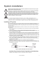
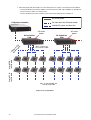
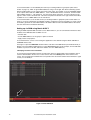
VC-Grid™
User Manual
Dimensions
All measurements are expressed in millimeters
185
185
18
© 2012 Martin Professional A/S. Information subject to change without notice. Martin Professional A/S and all affiliated companies
disclaim liability for any injury, damage, direct or indirect loss, consequential or economic loss or any other loss occasioned by the
use of, inability to use or reliance on the information contained in this document. The Martin logo, the Martin name and all other trademarks in this document pertaining to services or products by Martin Professional A/S or its affiliates and subsidiaries are trademarks
owned or licensed by Martin Professional A/S or its affiliates or subsidiaries.
P/N 35000263, Rev. B
Contents
Safety Information . . . . . . . . . . . . . . . . . . . . . . . . . . . . . . . . . . . . . . . . . . . . . . . . . . . . . . . . . . . . . . . . . . 4
Introduction . . . . . . . . . . . . . . . . . . . . . . . . . . . . . . . . . . . . . . . . . . . . . . . . . . . . . . . . . . . . . . . . . . . . . . . . 6
Electrostatic discharge precautions . . . . . . . . . . . . . . . . . . . . . . . . . . . . . . . . . . . . . . . . . . . . . . . . . . . . . 6
Unpacking . . . . . . . . . . . . . . . . . . . . . . . . . . . . . . . . . . . . . . . . . . . . . . . . . . . . . . . . . . . . . . . . . . . . . . . . 6
VC-Grid overview . . . . . . . . . . . . . . . . . . . . . . . . . . . . . . . . . . . . . . . . . . . . . . . . . . . . . . . . . . . . . . . . . . 7
Physical installation . . . . . . . . . . . . . . . . . . . . . . . . . . . . . . . . . . . . . . . . . . . . . . . . . . . . . . . . . . . . . . . . 8
System installation . . . . . . . . . . . . . . . . . . . . . . . . . . . . . . . . . . . . . . . . . . . . . . . . . . . . . . . . . . . . . . . . . 9
Installing a P3 system . . . . . . . . . . . . . . . . . . . . . . . . . . . . . . . . . . . . . . . . . . . . . . . . . . . . . . . . . . . . . . . 9
Installing a DMX-controlled system . . . . . . . . . . . . . . . . . . . . . . . . . . . . . . . . . . . . . . . . . . . . . . . . . . . . 11
System setup . . . . . . . . . . . . . . . . . . . . . . . . . . . . . . . . . . . . . . . . . . . . . . . . . . . . . . . . . . . . . . . . . . . . . 13
Setting up for P3 display . . . . . . . . . . . . . . . . . . . . . . . . . . . . . . . . . . . . . . . . . . . . . . . . . . . . . . . . . . . . 13
Setting up for DMX control. . . . . . . . . . . . . . . . . . . . . . . . . . . . . . . . . . . . . . . . . . . . . . . . . . . . . . . . . . . 13
Using the VC-Grid . . . . . . . . . . . . . . . . . . . . . . . . . . . . . . . . . . . . . . . . . . . . . . . . . . . . . . . . . . . . . . . . . 16
P3 display . . . . . . . . . . . . . . . . . . . . . . . . . . . . . . . . . . . . . . . . . . . . . . . . . . . . . . . . . . . . . . . . . . . . . . .
DMX control . . . . . . . . . . . . . . . . . . . . . . . . . . . . . . . . . . . . . . . . . . . . . . . . . . . . . . . . . . . . . . . . . . . . . .
Local control button . . . . . . . . . . . . . . . . . . . . . . . . . . . . . . . . . . . . . . . . . . . . . . . . . . . . . . . . . . . . . . . .
LED status feedback . . . . . . . . . . . . . . . . . . . . . . . . . . . . . . . . . . . . . . . . . . . . . . . . . . . . . . . . . . . . . . .
16
16
16
17
Service and maintenance . . . . . . . . . . . . . . . . . . . . . . . . . . . . . . . . . . . . . . . . . . . . . . . . . . . . . . . . . . 18
Cleaning. . . . . . . . . . . . . . . . . . . . . . . . . . . . . . . . . . . . . . . . . . . . . . . . . . . . . . . . . . . . . . . . . . . . . . . . . 18
Installing new software . . . . . . . . . . . . . . . . . . . . . . . . . . . . . . . . . . . . . . . . . . . . . . . . . . . . . . . . . . . . . 18
Troubleshooting . . . . . . . . . . . . . . . . . . . . . . . . . . . . . . . . . . . . . . . . . . . . . . . . . . . . . . . . . . . . . . . . . . 19
Specifications . . . . . . . . . . . . . . . . . . . . . . . . . . . . . . . . . . . . . . . . . . . . . . . . . . . . . . . . . . . . . . . . . . . . . 20
Safety Information
WARNING!
Read the safety precautions in this section before
installing, powering, operating or servicing this
product.
The following symbols are used to identify important safety information on the product and in this document:
Warning!
Warning!
Safety hazard.
Hazardous
Risk of severe voltage. Risk
injury or
of severe or
death.
lethal electric
shock.
Warning!
Fire hazard.
Warning!
Refer to
manual before
installing,
powering or
servicing.
Warning! Read this user manual before installing and operating the Martin VC-Grid™ and keep this
manual for future reference.
Warning! The VC-Grid is designed to integrate with other Martin™ devices in a video display
installation. Follow the safety precautions given not only in this user manual but also in the manuals
of all the devices you connect to it. Observe all warnings given in the manuals and printed on
devices. Install, connect and operate devices only as described in this manual and each device’s
manual and only in accordance with local laws and regulations. All Martin™ manuals are supplied
with devices and also available for download from www.martin.com.
Warning! The VC-Grid is not for household use. It presents risks of severe injury or death due to fire
and burn hazards, electric shock and falls. It must be installed by qualified technicians only.
Warning! The VC-Grid does not have user-serviceable parts. Refer any operation not described in
this manual to Martin™ or its authorized service agents.
If you have any questions about how to operate the VC-Grid safely, please contact your Martin™ supplier or
call the Martin™ 24-hour service hotline on +45 8740 0000, or in the USA on 1-888-tech-180.
PROTECTION FROM ELECTRIC SHOCK
• Connect the VC-Grid only to the Martin™ devices specified and installed as directed in this user manual.
• Check and respect the directions given in the user manuals of all the devices that you intend to connect to
the VC-Grid, particularly the instructions, warnings and limits that apply to:
- system layout,
- connections to other devices,
- specified cables,
- maximum cable lengths, and
- maximum number of devices that can be connected.
• Use only the cables specified by Martin™ for the devices concerned to interconnect them. If the specified
cables are not long enough for an intended cable run, consult Martin™ for assistance in finding or
creating a safe alternative cable
4
VC-Grid Safety and Installation Guide
• Each VC-Grid 8x8 25 consumes up to 30 W. Do not interconnect VC-Grids 8x8 25s in a chain with a total
power consumption that exceeds either:
- 360 W maximum or
- the maximum safe power rating of the DC output on the external PSU (power supply unit) used,
whichever is lower. Each time you reach 360 W – or the PSU output’s maximum power rating if lower than
360 W – use a new PSU output to continue connecting VC-Grids to 48 VDC power.
• When you create an interconnected chain of VC-Grids, do not allow the total length of the cables used in
the chain to exceed a maximum of 50 m (164 ft.) from the Martin P3 PowerPort 1500™ or the external
PSU to the last VC-Grid at the end of the chain
• Provide a means of locking out AC mains power that allows power to the installation to be shut down and
made impossible to reapply, even accidentally, during work on the installation.
• Shut down power to the installation during service and when it is not in use.
• Before applying power to the installation, check that all power distribution equipment and cables are in
perfect condition and rated for the current requirements of all connected devices.
• Isolate the installation from power immediately if the product, power cable or power plug are in any way
damaged, defective or wet, or if they show signs of overheating.
• Do not expose the VC-Grid to rain or moisture.
PROTECTION FROM BURNS AND FIRE
• Provide free airflow and a minimum clearance of 10 mm (0.4 in.) around the front of the VC-Grid.
• Do not operate the VC-Grid if the ambient temperature (Ta) exceeds 45° C (113° F).
• Do not modify the VC-Grid in any way not described in this manual or install other than genuine Martin™
parts. Use only accessories approved by Martin™.
PROTECTION FROM INJURY
• When installing the VC-Grid above ground level, ensure that the installation hardware and supporting
structure can hold at least 10 times the weight of all the devices they support.
• In an overhead installation or where the VC-Grid may cause injury if it falls:
- block access below the work area and work from a stable platform whenever installing, servicing or
moving the VC-Grid, and
- as soon as work is completed, check that all hardware and components are securely in place and
fastened to supporting structures.
Safety Information
5
Introduction
Thank you for selecting the Martin VC-Grid™. This compact LED-based display module is designed to
integrate into a Martin P3™ video system and can also be controlled using DMX.
The VC-Grid combines flexibility and simplicity with high-quality video display capabilities. Used with or
without a front diffuser, multiple VC-Grids can be combined in ways that give exceptional creative flexibility.
A hybrid power and data cabling system allows VC-Grids to be daisy-chained for easy setup and minimal
cabling.
The VC-Grid 8x8 25 is a square 8 x 8 array of LEDs with a 25 mm pitch (center-to-center distance). It offers
the following features:
• 64 individually controllable pixels
• 4000 nits brightness (calibrated mode)
• High-quality 16-bit per color image processing technology
• Pixel-level brightness and color calibration for optimal image quality
• P3 and DMX control with automatic protocol detection
• Intuitive pixel mapping and addressing using a Martin P3™ system controller
• Single hybrid cable for power and data input and throughput
• RGB, warm white, medium white and cool white versions
• External power and data processor (Martin P3 PowerPort 1500™) and simple cabling system
Martin™ user documentation is supplied with products and available for download from the Martin™
website at http://www.martin.com, where you can also find the latest specifications, firmware updates and
support information for all Martin™ products.
Martin™ welcomes input from users. Comments or suggestions regarding this manual can be e-mailed to
[email protected] or posted to: Technical Documentation, Martin Professional A/S, Olof Palmes Allé 18,
DK-8200 Aarhus N, Denmark.
Electrostatic discharge precautions
Important! Components on the VC-Grid are sensitive to damage by ESD (electrostatic discharge).
Take the following precautions:
• Store the VC-Grid only in its ESD shielding bag and do not remove it until you are ready to install
it, and return it to its ESD shielding bag immediately if you remove it from an installation. Place it
on grounded (earthed) surfaces only.
• Hold the VC-Grid only by its edges. Avoid touching conductive surfaces. Avoid touching
components apart from the connectors and the control button. Avoid touching connector pins.
• Attach an ESD wrist strap to your wrist and connect its ground (earth) lead to a known ground
(earth) before handling the VC-Grid.
Unpacking
The VC-Grid is supplied in anti-static packaging, Leave products in their packaging until you are ready to
install them.
6
VC-Grid Safety and Installation Guide
VC-Grid overview
A
C
B
A - Control button
B - 48 VDC power + data throughput (THRU)
C - 48 VDC power + data input (IN)
Figure 1: Overview
VC-Grid overview
7
Physical installation
The VC-Grid can be installed in any orientation.
The backs of modules are marked with arrows and the word TOP. To ensure the most evenly matched
optical characteristics when viewing VC-Grids at an angle, install all modules with the arrows facing the
same way. In vertical arrays, install all modules with the arrows pointing upwards and the TOP marking at
the upper edge of the modules.
Allow free airflow around the product and at least 10 mm (0.4 in.) of clearance around the LEDs on the front
surface.
If you want to maintain 25 mm pixel spacing across multiple VC-Grid 8x8 25s so that they form a seamless
display surface, install them with a 15 mm (0.59 in.) gap between their edges, both horizontally and
vertically.
Figure 2: Mounting method
See Figure 2. The VC-Grid can be fastened to a surface or structure by installing pillar bolts evenly around
the product using any four of the mounting holes (arrowed).
8
VC-Grid Safety and Installation Guide
System installation
Warning! Connect the VC-Grid™ only to the devices specified in this manual and only using the
Martin™ cables specified in this manual.
Warning! Do not exceed the maximum numbers of devices that can be connected and maximum
cable lengths specified in this manual and the manuals of the devices in the system.
Warning! Do not interconnect more than a total of twelve VC-Grid 8x8 25s in one linked chain or
interconnect VC-Grids in one linked chain that will exceed the maximum power rating of the PSU,
whichever limit is reached first. Do not connect more than one linked chain of VC-Grids to one
output from a Martin P3 PowerPort 1500™.
The VC-Grid is designed to display either Martin P3™ video or DMX-controlled lighting effects. It
automatically recognizes and responds to either a Martin P3™ or a DMX data signal. The next sections
explain how to create a VC-Grid installation to display P3 video data or DMX-controlled lighting effects.
Installing a P3 system
The P3 link requires Ethernet Cat 5e or better network cable. The cable run between any two devices on the
link can be up to 100 m (328 ft.) in length. If necessary, a cable run can be extended beyond 100 m by
inserting an unmanaged Ethernet switch or using a fiber-optic system (see the P3™ system controller user
manual for details).
To install a system that displays Martin P3™ video on VC-Grids, see the overview in Figure 4 and follow
these directions:
1. Make sure that no devices in the installation can be connected to AC mains power until all installation
work is complete.
2. Read “Safety Information” on page 4 and ”Electrostatic discharge precautions” on page 6.
3. Create a P3 video data link from a Martin P3™ system controller such as the P3-100™, P3-200™ or P3
PC™ to a Martin P3 PowerPort 1500™.
4. If required, continue the P3 video data link in a daisy-chain by connecting the P3 data throughput of one
P3 PowerPort 1500™ to the P3 data input of the next, as described in the P3 PowerPort 1500™ user
manual. You can connect up to fifty P3 PowerPort 1500s in a P3 data daisy-chain like this. If you need to
connect more than fifty, use an unmanaged Ethernet switch to split the P3 data link into branches, each
containing less than fifty P3 PowerPort 1500s.
5. Connect VC-Grids together in daisy-chained hybrid links using Martin™ hybrid PCB-to-PCB cables (see
”Power + data VC-Grid to VC-Grid link cables” on page 21). Connect each cable from the THRU
connector on one VC-Grid to the IN connector on the next VC-Grid (VC-Grid connectors are shown in
”VC-Grid overview” on page 7).
Warning! Each hybrid link may contain up to a maximum of twelve VC-Grid 8x8 25s.
6. Connect each hybrid link of VC-Grids to one of the four 4-pin female XLR hybrid (48 VDC power + P3
data) outputs on a P3 PowerPort 1500™ using a Martin™ hybrid 4-pin male XLR to PCB adapter cable,
P/N 11840158 (see Figure 3).
From 48 VDC +
P3 data source
Power + data
to VC-Grid
Figure 3: Hybrid-to-PCB adapter cable, P/N 11840158
If this adapter cable is not long enough, extend it by inserting a Martin™ 4-pin XLR hybrid extension
cable between the adapter cable and the P3 PowerPort 1500™ hybrid output. This extension cable is
available in various lengths (see ”Power + data extension cables” on page 21).
System installation
9
7. When the P3 link and all VC-Grids are connected and you are ready to set up and test the installation:
• Connect the Martin P3 PowerPort 1500™ to AC mains power at 100 - 240 V, 50/60 Hz as described in
the P3 PowerPort 1500™ user manual, then
• connect the Martin P3 system controller to AC mains power and power the controller on.
AC mains power
P3 video data link (Ethernet cable)
P3 System Controller
Hybrid (DC power and data) link
AC mains
power
P3 PowerPort
1500
Max. 4 chains per
P3 PowerPort 1500
Hybrid PCBto-PCB cable
Hybrid PCBto-PCB cable
H
y
ad bri
ap d-t
te o-P
rc C
ab B
le
P3 PowerPort
1500
AC mains
power
Max. 12 VC-Grid 8x8 25s
total per hybrid link
Figure 4: P3 system layout
10
VC-Grid Safety and Installation Guide
Installing a DMX-controlled system
The DMX link requires DMX cable. It can be maximum 300 m (1000 ft.) in length, but this can be extended
using an RDM-compliant amplifier/splitter such as the Martin RDM 5.5 Splitter™, P/N 90758150. The link
must run in one single daisy-chain but you can split it into separate branches each time you insert an
amplifier/splitter. If you would like assistance with creating a DMX link, your Martin™ supplier will be glad to
advise.
The number of VC-Grids per DMX link is limited by the 512 DMX channels available in one DMX universe at
the DMX controller. Each time you reach 512 channels, you must create a new DMX link in a new DMX
universe. Note that this limit applies to the DMX link. The maximum safety limits that apply to the hybrid link
(see “Safety Information” on page 4) must be respected in all cases.
To install a system that displays DMX-controlled lighting effects on VC-Grids, see the overview in Figure 6.
and follow these directions:
1. Make sure that no devices in the installation can be connected to AC mains power until all installation
work is complete.
2. Read “Safety Information” on page 4 and ”Electrostatic discharge precautions” on page 6.
3. Run a DMX cable from a DMX/RDM controller such as the Martin M1™ or M-PC™ to either:
• a Martin hybrid lead-in cable, P/N 11840171 (see Figure 5), or
• a DMX/RDM Splitter such as the Martin 5.5 RDM Splitter™, P/N 90758150, and then to a Martin
hybrid lead-in cable P/N 11840171 (see Figure 5).
4. Connect VC-Grids together in daisy-chained hybrid links using Martin™ hybrid PCB-to-PCB cables (see
”Power + data VC-Grid to VC-Grid link cables” on page 21). Connect each cable from the THRU
connector on one VC-Grid to the IN connector on the next VC-Grid (VC-Grid connectors are shown in
”VC-Grid overview” on page 7).
Warning! Each VC-Grid hybrid link may contain up to the lower of these two limits:
• either a maximum of twelve VC-Grid 8x8 25s
• or the maximum number of VC-Grids that can be interconnected without exceeding the power rating of
the external PSU (power supply unit) output that the hybrid link will be connected to.
5. See Figure 5. Connect a Martin™ hybrid-to-PCB adapter cable (P/N 11840158) to the first VC-Grid of
each hybrid link, then connect it to the Martin™ hybrid lead-in cable (P/N 11840171).
6. Connect the two DC power wires on the hybrid lead-in cable to a DC output on a 48 VDC PSU such as
the Mean Well SP-480 48. Connect the white wire to positive (+ve) and the black wire to negative (-ve).
7. Connect the 5-pin male XLR connector on the hybrid lead-in cable to an RDM-compliant DMX controller.
Hybrid lead-in cable, P/N 11840171
From DMX/RDM
controller
5-pin male XLR
From 48 VDC PSU
white to +ve, black to -ve
4-pin female XLR
Hybrid-to-PCB adapter cable, P/N 11840158
4-pin male XLR
To VC-Grid™
daisy chain
PCB connector
insert extension cable
if required
Figure 5: Power and DMX data input to a VC-Grid daisy-chain
If you need a longer cable run to a VC-Grid daisy chain, extend the arrangement shown in Figure 5 by
inserting a Martin™ 4-pin XLR hybrid extension cable between the Hybrid lead-in cable P/N 11840171
and the Hybrid-to-PCB adapter cable P/N 11840158. Hybrid extension cable is available from Martin™
in various lengths. See ”Power + data extension cables” on page 21 for ordering information.
8. When the DMX link, 48 VDC power link and all VC-Grids are connected and you are ready to set up and
test the installation:
• Connect the external PSU to AC mains power as described in its user manual, then
• connect the DMX controller to AC mains power and power the controller on.
System installation
11
DMX/RDM Controller
48 VDC power
DMX link (DMX cable)
Hybrid (DC power and data) link
DMX/RDM Splitter (if needed)
48 VDC
external PSU
48 VDC
external PSU
Hybrid lead-in
cable
Hybrid lead-in
cable
Hybrid extension
cable
(if needed)
Hybrid extension
cable
(if needed)
Hybrid-to-PCB
adapter cable
Hybrid-to-PCB
adapter cable
Hybrid PCBto-PCB cable
Hybrid PCBto-PCB cable
Hybrid PCBto-PCB cable
Hybrid PCBto-PCB cable
See text for max. number of
of VC-Grids per hybrid link
See text for max. number of
of VC-Grids per hybrid link
Figure 6: DMX system layout
12
VC-Grid Safety and Installation Guide
System setup
Warning! Before applying power to the VC-Grid:
• Carefully review the safety information starting on page 4
• Check that the installation is safe and secure.
Setting up for P3 display
A Martin P3™ system allows video to be displayed on an installation that consists of or includes VC-Grid
devices. When a P3 controller is connected to the data link and the installation is powered on, you can set
up all the devices on the link from the P3 controller. See the P3 controller user manual for details.
Setting up for DMX control
A DMX system gives 0 - 100% variable intensity control. Varying the intensity of red, blue and green LEDs in
RGB products provides RGB color mixing.
You can set up and control a VC-Grid installation over the data link using an RDM-compatible DMX
controller such as the Martin M-PC™ Windows application (running on a PC connected to a USB/DMX
interface such as the Martin USB Duo™ DMX Interface) or the Martin M1™ DMX/RDM control console. The
interface on the Martin M1™ monitor screen is basically identical to the Martin M-PC™ interface.
DMX control channels
DMX controllers send control data on DMX control channels in DMX universes. One DMX universe has 512
channels available. RGB control of each individually controlled element in an installation requires three
channels, white intensity control requires one channel.
A VC-Grid installation can be controlled as groups of pixels or as individual pixels:
• A group can consist of an entire installation, any part of an installation or separate 8 x 8 VC-Grid modules.
In grouped control, all the LEDs in one group are controlled using the same DMX channels – three
channels for RGB products and one channel for WW, MW and CW products.
• If VC-Grids are set up for individual pixel control, each of the 64 LEDs on a module is controlled by its own
DMX channels.
A VC-Grid installation uses the number of DMX channels required by the group or pixel (three channels for
RGB and one channel for WW, MW or CW) multiplied by the total number of groups or pixels in the
installation. For example, an installation with fifty RGB modules will require:
• 3 DMX channels if the entire installation is controlled as one group,
• 3 channels x 10 groups = 30 DMX channels if the installation is divided into ten groups that are controlled
individually,
• 3 channels x 50 modules = 150 DMX channels if each of the fifty modules is controlled as an individual
group, and
• 3 channels x 50 modules x 64 pixels = 9600 DMX channels if each of the 3200 pixels is controlled
individually (in this example, 19 DMX universes will be required because one DMX universe has 512
channels).
Individual and grouped control can be mixed freely in an installation. For example, some VC-Grid modules
can be set up for individual pixel control, other modules can be set up for individual module control, and
other modules can be put into groups for grouped control of multiple modules.
DMX addresses
The system must be set up so that each individually controlled group or pixel receives instructions from the
DMX controller on its own DMX channels. The DMX address, also known as the control address or start
channel, is the first of these channels. If a unit uses more than one channel, it uses the DMX address
channel and the channels immediately above it. For example, one VC-Grid RGB module controlled as one
group and set to DMX address 1 will use DMX channels 1 - 3. Channel 4 will be available for use as a DMX
address for the next device.
System setup
13
If a VC-Grid module is set to individual pixel control (see “Setting modules to grouped or pixel control
modes” on page 15), LEDs are given DMX addresses using a ‘left-to-right, then down’ numbering system
(like the reading order you are using for the words on this page). For example, if one VC-Grid RGB module
is set to pixel control and set to DMX address 1, each of the 64 LEDs will use 3 channels, and the module
will use DMX channels 1 - 192 (Channel 1 -3 for the top-left pixel, channels 4 - 6 for the next pixel on the
right etc. until it reaches channels 190 - 192 for the last pixel at the bottom on the right. Channel 193 will be
available for use as a DMX address for the next device.
If a VC-Grid module is set to module control (see “Setting modules to grouped or pixel control modes” on
page 15), it can be controlled as an individual module or assigned to a group of modules. To create a group
of modules, give them the same DMX address. All modules that have the same DMX address will receive
the same instructions and behave identically.
Setting up via RDM using Martin M-PC™
Using an RDM-compliant DMX controller such as Martin M-PC™, you can communicate with the VC-Grid
modules on the DMX data link via RDM. You can:
• Retrieve data
• Set the DMX addresses of the groups or pixels on the link
• Apply various setup options.
To use Martin M-PC, connect a PC running this application to the data link using the Martin USB Duo™
USB/DMX interface box.
See Figure 7. Open the RDM View window in M-PC and click on the Scan button (arrowed bottom left) to
display a list of the RDM-compliant devices on the DMX/RDM data link (in this example, ten VC-Grid RGB
modules are present on the link, and all ten modules are set to DMX address 1).
Identifying VC-Grids in the installation
To see which VC-Grid module in this list corresponds to which VC-Grid module in the installation, click on
each VC-Grid module in the list once to select it, then click on the Identify button at the bottom of the
screen. The VC-Grid in the installation that corresponds to the selected VC-Grid in the list will flash a signal
so that you can identify it.
Figure 7: M-PC RDM View
14
VC-Grid Safety and Installation Guide
Setting DMX Addresses
See Figure 7. To set DMX addresses using the M-PC application, open the RDM View window and click on
Scan to display a list of the elements in the installation. Click in the Address box for each VC-Grid module
and enter the desired DMX address, then press the Enter key to store the DMX address for that module.
Remember that modules with identical addresses will receive the same instructions.
When working with more than one DMX universe, click in the Universe box for each VC-Grid module, enter
the desired DMX universe number, then press the Enter key to store the DMX universe for that module.
Setting modules to grouped or pixel control modes
In pixel mode, the 64 LEDs on a module are controlled individually. In module mode, All the LEDs on one
module are controlled as one group.
To set a VC-Grid module to pixel or module mode, calibrated or raw, using M-PC, open the RDM View
window and click on Scan to display a list of the elements in the installation. Select the module in the list,
then click on the Properties... button at the bottom of the screen to open the Properties window for that
module. Select from:
• Pixel mode (calibrated)
• Module mode (calibrated)
• Pixel mode (raw)
• Module mode (raw)
Calibrated and raw modes
See the section on setting control modes above.
In calibrated mode, color and intensity levels are evenly matched in different LEDs and different modules but
maximum output is slightly reduced.
In raw mode, LEDs give maximum possible output but color and intensity levels may be slightly uneven in
different LEDs and different modules.
System setup
15
Using the VC-Grid
Warning! Before applying power to the VC-Grid:
• Carefully review the safety information starting on page 4
• Check that the installation is safe and secure.
Do not use the VC-Grid if the ambient temperature exceeds 45° C (113° F) or falls below -20° C (-4° F).
P3 display
The VC-Grid will display video from all common video sources sent via a P3 controller. See the P3 controller
documentation for details.
DMX control
The VC-Grid will display effects controlled by DMX. An RDM-compatible controller is strongly
recommended, as RDM allows two-way communication. See the controller documentation for details.
Local control button
The small control button on the back of the VC-Grid (see Figure 1 on page 7) lets you display the product’s
status, test the LEDs and reset the VC-Grid.
Test patterns are stored in onboard memory. This lets you test the LEDs without an external controller.
Table 1 below lists the control button functions:
Button action
Short press
Function
The first press displays status as shown in Table 2 for a few seconds.
The next presses display the following test patterns on the LEDs (one
short press scrolls to next pattern):
- Calibrated white
- Full red
- Full green
- Full blue
- Vertical scrolling gradient
Press and hold until
all LEDs light blue
Reboot the VC-Grid.
Press and hold until
all LEDs light white
Return the VC-Grid to its default factory firmware.
Table 1: Key to control button functions
The test patterns that are stored in internal memory let you check that the video display products in an
installation are correctly connected without the need for a P3 system controller.
Note that test patterns can also be called up on P3 system controllers and the P3 PowerPort 1500™.
16
VC-Grid Safety and Installation Guide
LED status feedback
The VC-Grid gives status information via its LEDs as shown in Table 2:
Color
Output
Indication
Action required
Blue
Constant
Busy (e.g. booting up or writing to
flash memory).
Wait a moment for normal operation
to be resumed.
Red
Constant
Error. The VC-Grid has encountered
a fatal error and can not run.
Perform a factory reboot, followed by
a firmware upload.
Red
Flashing
No control source detected.
Connect a P3 system controller or
DMX source to the network.
Green
Flashing
Ready. VC-Grid connected to P3
controller but not receiving valid P3
data stream.
Set up the P3 controller to use the
products connected to the VC-Grid.
Green
Constant
Running normally in P3 mode.
None.
Cyan
Flashing
Ready. VC-Grid connected to DMX
controller but not receiving valid
DMX data stream.
Set up the DMX controller to use the
products connected to the VC-Grid.
Cyan
Constant
Running normally in DMX mode.
None.
Table 2: Key to LED status information
To display status, press the control button once. Four LEDs will give one of the indications listed in Table 2
for a few seconds.
Using the VC-Grid
17
Service and maintenance
Warning! Read “Safety Information” on page 4 before carrying out service on the VC-Grid.
Warning! Isolate the installation from AC mains power before servicing.
Warning! Refer any service operation not described in this manual to a qualified service
technician.
Important! Read ”Electrostatic discharge precautions” on page 6 before carrying out
service on the VC-Grid.
Important! Excessive dust buildup causes overheating and a risk of short-circuits and will
damage the product. Damage caused by inadequate cleaning is not covered by the product
warranty.
The user will need to clean the VC-Grid periodically. All other service operations on the VC-Grid must be
carried out by Martin Professional™ or its approved service agents.
Installation, on-site service and maintenance can be provided worldwide by the Martin Professional Global
Service organization and its approved agents, giving owners access to Martin’s expertise and product
knowledge in a partnership that will ensure the highest level of performance throughout the product’s
lifetime. Please contact your Martin supplier for details.
Cleaning
Cleaning schedules vary greatly depending on the operating environment. It is therefore impossible to
specify precise cleaning intervals for the VC-Grid. In extreme cases, the product may require cleaning after
surprisingly few hours of operation. Environmental factors that may result in a need for frequent cleaning
include:
• Use of smoke or fog machines.
• High airflow rates (near air conditioning vents, for example).
• Presence of cigarette smoke.
• Airborne dust (from stage effects, building structures and fittings or the natural environment in outdoor
locations, for example).
If one or more of these factors is present, inspect products soon after installing them to see whether
cleaning is necessary. Check again at frequent intervals. This procedure will allow you to assess cleaning
requirements in your particular situation. If in doubt, consult your Martin™ dealer about a suitable
maintenance schedule.
Important!
Electrostatic discharges may cause damage. Do not touch the VC-Grid with fingers or a compressed
air nozzle.
To clean the product, use low-pressure compressed air to gently remove dust and loose particles from the
front and back of the product. Avoid touching the product’s conductive surfaces and electronic components.
Installing new software
It may be necessary to upload new software (i.e. device firmware) to the VC-Grid if it appears to have a
software-related fault or if you want to update to a newer software version.
Software for Martin™ products is available from the Martin website. The VC-Grid software can be installed
from the P3 System Controller over the P3 data link. See the P3 System Controller user manual for software
installation instructions.
18
VC-Grid Safety and Installation Guide
Troubleshooting
Problem
Control is lost and pressing
control button causes VC-Grid
to show constant or flashing red
status indication.
Product is completely dead.
VC-Grid does not display as
intended.
Probable cause(s)
Remedy
Error has occurred.
Check that system is correctly connected, set up
and running.
Hold control button pressed in until it turns blue,
then release, to reboot VC-Grid.
Restart P3 or DMX controller.
No DC power to product.
Check 48 VDC power supply and cables
Internal fault.
Disconnect from power. Do not attempt repairs
yourself. Contact Martin™ Service or an authorized
Martin™ service partner for assistance.
Bad 48 VDC power transmission.
Inspect connections and cables. Correct poor
connections. Repair or replace damaged cables.
Bad data transmission.
Inspect connections and cables. Correct poor
connections. Repair or replace damaged cables.
Incorrect mapping or addressing of products.
Check product address and controller settings.
Product in installation is defective and is
disturbing data transmission.
Substitute known good products one at a time until
normal operation is regained. Have faulty product
serviced by Martin™ Service.
Table 3: Troubleshooting
Troubleshooting
19
Specifications
Physical
Length . . . . . . . . . . . . . . . . . . . . . . . . . . . . . . . . . . . . . . . . . . . . . . . . . . . . . . . . . . . . . . . . .185 mm (7.3 in.)
Width . . . . . . . . . . . . . . . . . . . . . . . . . . . . . . . . . . . . . . . . . . . . . . . . . . . . . . . . . . . . . . . . . .185 mm (7.3 in.)
Height . . . . . . . . . . . . . . . . . . . . . . . . . . . . . . . . . . . . . . . . . . . . . . . . . . . . . . . . . . . . . . . . . .18 mm (0.7 in.)
Control and programming
Control options. . . . . . . . . . . . . Martin™ P3 System Controller (via Martin™ P3 PowerPort 1500) or DMX
Protocol detection . . . . . . . . . . . . . . . . . . . . . . . . . . . . . . . . . . . . . . . . . . . . . . . . . . . . . . . . . . . . . Automatic
Control modes . . . . . . . . . . . . . . . . . . . . . . . . . . . . . . . . . . . . . . . . . . Calibrated and raw, pixel and module
DMX channels (RGB) . . . . . . . . . . . . . . . . . . . . . . . . . . . . . . . . . . . . 192 (pixel mode) or 3 (module mode)
DMX channels (WW, MW and CW) . . . . . . . . . . . . . . . . . . . . . . . . . . . 64 (pixel mode) or 1 (module mode)
Setting and addressing . . . . . . . . . . . . . . . . . . . . . . . . . P3 System controller or RDM-compliant controller
Control resolution. . . . . . . . . . . . . . . . . . . . . . . . . . . . . . . . . 16-bit (P3) or 8-bit (DMX) control of each color
Color and intensity calibration . . . . . . . . . . . . . . . . . . . . . . . . . . . . . . . . . . . . . . . . . . . . . . . . . . . .Pixel-level
Video signal compliance . . . . . . . . . . . . . . . . . . . . . . . . . . . . . . . . . . . . . . Martin P3™ proprietary protocol
DMX compliance . . . . . . . . . . . . . . . . . . . . . . . . . . . . . . . . . . . . . . . . . . . . . . . . . . . . . . . USITT DMX512-A
RDM compliance . . . . . . . . . . . . . . . . . . . . . . . . . . . . . . . . . . . . . . . . . . . . . . . . . . . . . . . ANSI/ESTA E1.20
Firmware update . . . . . . . . . . . . . . . . . . . . . . . . . . . . . . . . . . . . . . . . . . . . . . . . . .Via P3 System Controller
Optics
Minimum LED lifetime . . . . . . . . . . . . . . . . . . . . . . . . . . . . . . . . . 50 000 hours (to >70% luminous output)*
*Manufacturer´s figure obtained under manufacturer´s test conditions
Control/user interface
Device status . . . . . . . . . . . . . . . . . . . . . . . . . . . . . . . . . . . . . . . . . . . . . . . . . . . Multi-color visual indication
Device test . . . . . . . . . . . . . . . . . . . . . . . . . . . . . . . . Control pushbutton on rear calls up local test patterns
Device reset . . . . . . . . . . . . . . . . . . . . . . . . . . . . . . . . . . . . . . . . . . . . . . . . . . . . Control pushbutton on rear
Video processing
Brightness control
Gamma correction and control
Color temperature control
Calibration processing
Synchronization
Photometric Data
Pixels per module . . . . . . . . . . . . . . . . . . . . . . . . . . . . . . . . . . . . . . . . . . . . . . . . . . . . . . . . . . . . . . . . . . . 64
Color temperature, WW . . . . . . . . . . . . . . . . . . . . . . . . . . . . . . . . . . . . . . . . . . . . . . . . . . . . . . . . . . . 2700 K
Color temperature, MW . . . . . . . . . . . . . . . . . . . . . . . . . . . . . . . . . . . . . . . . . . . . . . . . . . . . . . . . . . . 4000 K
Color temperature, CW . . . . . . . . . . . . . . . . . . . . . . . . . . . . . . . . . . . . . . . . . . . . . . . . . . . . . . . . . . . 6500 K
Luminous intensity, RGB, calibrated mode . . . . . . . . . . . . . . . . . . . . . . . . . . . . . . . . . . . . . . . . . . . 4000 Nit
Luminous intensity, RGB, raw mode . . . . . . . . . . . . . . . . . . . . . . . . . . . . . . . . . . . . . . . . . . . . . . . . 5000 Nit
Luminous intensity, WW, calibrated mode . . . . . . . . . . . . . . . . . . . . . . . . . . . . . . . . . . . . . . . . . . .10 000 Nit
Luminous intensity, WW, raw mode . . . . . . . . . . . . . . . . . . . . . . . . . . . . . . . . . . . . . . . . . . . . . . . .11 000 Nit
Luminous intensity, MW, calibrated mode . . . . . . . . . . . . . . . . . . . . . . . . . . . . . . . . . . . . . . . . . . .10 000 Nit
Luminous intensity, MW, raw mode . . . . . . . . . . . . . . . . . . . . . . . . . . . . . . . . . . . . . . . . . . . . . . . .11 000 Nit
Luminous intensity, CW, calibrated mode . . . . . . . . . . . . . . . . . . . . . . . . . . . . . . . . . . . . . . . . . . .10 000 Nit
Luminous intensity, CW, raw mode . . . . . . . . . . . . . . . . . . . . . . . . . . . . . . . . . . . . . . . . . . . . . . . .11 000 Nit
Viewing angle. . . . . . . . . . . . . . . . . . . . . . . . . . . . . . . . . . . . . . . . . . . . . . . . . . . . . . . . . . . . . . . 120° x 120°
Preliminary data, figures are approximate
System Integration
P3 PowerPort 1500™ . . . . . . . . . . . . . . . . . . . . . . . . . . . . . . . . . . . . . . . . . . . . . . . . . . . . . . P/N 90721040
See www.martin.com for latest information.
20
VC-Grid Safety and Installation Guide
Construction
Base. . . . . . . . . . . . . . . . . . . . . . . . . . . . . . . . . . . . . . . . . . . . . . . . . . . . . . . . . . . . . Black FR4 circuit board
Transparency through module (unmasked area) . . . . . . . . . . . . . . . . . . . . . . . . . . . . . . . . . . . . . . . . . . 37%
Protection rating. . . . . . . . . . . . . . . . . . . . . . . . . . . . . . . . . . . . . . . . . . . . . . . . . . . . . . . . . . . . . . . . . . . IP20
RoHS compliant
Installation
Orientation . . . . . . . . . . . . . . . . . . . . . . . . . . . . . . . . . . . . . . . . . . . . . . . . . . . . . . . . . . . . . . . . . . . . . . . .Any
Maximum number of VC-Grid™ 8x8 25 modules per daisy-chain. . . . . . . . . . . . . . . . . . . . . . . . . . . . . . . 12
Mounting method . . . . . . . . . . . . . . . . . . . . . . . . . . . . . . . . . . . . . . . . . . . . . . . . . Mounting holes in module
Minimum clearance around front surface. . . . . . . . . . . . . . . . . . . . . . . . . . . . . . . . . . . . . . . .10 mm (0.4 in.)
Connections
Power & data input. . . . . . . . . . . . . . . . . . . . . . . . . . . . . . . . . . . . . . . . . . 4-pin Molex male PCB connector
Power & data thru . . . . . . . . . . . . . . . . . . . . . . . . . . . . . . . . . . . . . . . . . 4-pin Molex female PCB connector
Electrical
Nominal input voltage . . . . . . . . . . . . . . . . . . . 48 VDC from Martin P3 PowerPort 1500™ or external PSU
Typical power consumption . . . . . . . . . . . . . .30 W (including cable in 50 m chain), full load at full intensity
Typical current draw . . . . . . . . . . . . . . . . . .0.625 A (including cable in 50 m chain), full load at full intensity
Thermal
Cooling. . . . . . . . . . . . . . . . . . . . . . . . . . . . . . . . . . . . . . . . . . . . . . . . . . . . . . . . . . . . . . . . . . . . . Convection
Maximum ambient temperature (Ta max.) . . . . . . . . . . . . . . . . . . . . . . . . . . . . . . . . . . . . . . . 45° C (113° F)
Minimum ambient temperature (Ta min.) . . . . . . . . . . . . . . . . . . . . . . . . . . . . . . . . . . . . . . . . . -20° C (-4° F)
Approvals
EU safety . . . . . . . . . . . . . . . . . . . . . . . . . . . . . . . . . . . . . . . EN 60950-1
EU EMC . . . . . . . . . . . . . . . . . . . . EN 55103-1, EN 55103-2, EN 55022,
. . . . . . . . . . . . . . . . . . . . . . . . EN 55024, EN 61000-3-2, EN 61000-3-3
US safety . . . . . . . . . . . . . . . . . . . . . . . . . . . . . . . . . . . . . . . UL 60950-1
US EMC . . . . . . . . . . . . . . . . . . . . . . . . . . . . . . . . . FCC Part 15 Class A
Canadian safety . . . . . . . . . . . . . . . . . . . . . . . . CSA C22.2 No. 60950-1
Canadian EMC. . . . . . . . . . . . . . . . . . . . . . . . . . . . . . ICES-003 Class A
Australia/NZ . . . . . . . . . . . . . . . . . . . . . . . . . . . . . . . . . . . . C-Tick N4241
Accessories
Power + data adapter cables
Hybrid adapter cable, 4-pin male XLR to PCB connector, 0.25 m (0.8 ft.). . . . . . . . . . . . . . .
Hybrid adapter cable, PCB to 4-pin XLR female, 0.25 m (0.8 ft.) . . . . . . . . . . . . . . . . . . . . .
Hybrid lead-in adapter cable, 5-pin male XLR + two
cable tails to 4-pin female XLR, 0.25 m (0.8 ft.) . .
Power + data VC-Grid to VC-Grid link cables
Hybrid link cable, PCB to PCB, 200 mm (7.9 in.). . . . . . . . . . . . . . . . . . . . . . . . . . . . . . . . . .
Hybrid link cable, PCB to PCB, 400 mm (15.7 in.). . . . . . . . . . . . . . . . . . . . . . . . . . . . . . . . .
Hybrid link cable, PCB to PCB, 600 mm (23.6 in.). . . . . . . . . . . . . . . . . . . . . . . . . . . . . . . . .
Hybrid link cable, PCB to PCB, 800 mm (31.5 in.). . . . . . . . . . . . . . . . . . . . . . . . . . . . . . . . .
Hybrid link cable, PCB to PCB, 1000 mm (39.4 in.). . . . . . . . . . . . . . . . . . . . . . . . . . . . . . . .
Power + data extension cables
Hybrid 4-pin XLR extension cable, 1 m (3.3 ft.) . . . . . . . . . . . . . . . . . . . . . . . . . . . . . . . . . . .
Hybrid 4-pin XLR extension cable, 2.5 m (8.2 ft.) . . . . . . . . . . . . . . . . . . . . . . . . . . . . . . . . .
Hybrid 4-pin XLR extension cable, 5 m (16.4 ft.) . . . . . . . . . . . . . . . . . . . . . . . . . . . . . . . . . .
Hybrid 4-pin XLR extension cable, 10 m (32.8 ft.) . . . . . . . . . . . . . . . . . . . . . . . . . . . . . . . . .
Hybrid 4-pin XLR extension cable, 25 m (82.0 ft.) . . . . . . . . . . . . . . . . . . . . . . . . . . . . . . . . .
P/N 11840158
P/N 11840159
P/N 11840171
P/N 11840160
P/N 11840161
P/N 11840162
P/N 11840163
P/N 11840157
P/N 11821016
P/N 11821017
P/N 11821018
P/N 11821019
P/N 11821015
Hybrid cables carry both DC power and data over separate conductors.
Specifications
21
Related Items
P3 PowerPort 1500™ . . . . . . . . . . . . . . . . . . . . . . . . . . . . . . . . . . . . . . . . . . . . . . . . . . . . . .
P3-100™ System Controller . . . . . . . . . . . . . . . . . . . . . . . . . . . . . . . . . . . . . . . . . . . . . . . . .
P3-200™ System Controller . . . . . . . . . . . . . . . . . . . . . . . . . . . . . . . . . . . . . . . . . . . . . . . . .
P3-PC™ System Controller . . . . . . . . . . . . . . . . . . . . . . . . . . . . . . . . . . . . . . . . . . . . . . . . . .
M-PC™ Pro (up to 64 DMX universes) incl. Martin USB Duo™ DMX Interface Box. . . . . . .
Martin RDM 5.5 Splitter™ . . . . . . . . . . . . . . . . . . . . . . . . . . . . . . . . . . . . . . . . . . . . . . . . . . .
P/N 90721040
P/N 90721010
P/N 90721020
P/N 90721030
P/N 90732010
P/N 90758150
See www.martin.com for latest information
Ordering information
VC-Grid™ 8x8 25 RGB . . . . . . . . . . . . . . . . . . . . . . . . . . . . . . . . . . . . . . . . . . . . . . . . . . . . .
VC-Grid™ 8x8 25 WW. . . . . . . . . . . . . . . . . . . . . . . . . . . . . . . . . . . . . . . . . . . . . . . . . . . . . .
VC-Grid™ 8x8 25 MW . . . . . . . . . . . . . . . . . . . . . . . . . . . . . . . . . . . . . . . . . . . . . . . . . . . . . .
VC-Grid™ 8x8 25 CW . . . . . . . . . . . . . . . . . . . . . . . . . . . . . . . . . . . . . . . . . . . . . . . . . . . . . .
P/N 90357010
P/N 90357000
P/N 90357030
P/N 90357020
Specifications subject to change without notice. For the latest product specifications, see www.martin.com
FCC Compliance
This device complies with Part 15 of the FCC Rules. Operation is subject to the following two conditions: (1) This device may not
cause harmful interference, and (2) this device must accept any interference received, including interference that may cause
undesired operation.
Canadian Interference-Causing Equipment Regulations - Règlement sur le Matériel Brouilleur du Canada
This Class A digital apparatus meets all requirements of the Canadian Interference-Causing Equipment Regulations.
Cet appareil numérique de la classe A respecte toutes les exigences du Règlement sur le Matériel Brouilleur du Canada.
Disposing of this product
Martin™ products are supplied in compliance with Directive 2002/96/EC of the European Parliament and of the
Council of the European Union on WEEE (Waste Electrical and Electronic Equipment), as amended by Directive
2003/108/EC, where applicable.
Help preserve the environment! Ensure that this product is recycled at the end of its life. Your supplier can give
details of local arrangements for the disposal of Martin products.
www.martin.com • Olof Palmes Allé 18 • 8200 Aarhus N • Denmark
Tel: +45 8740 0000 • Fax +45 8740 0010