1
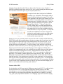
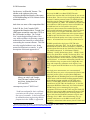
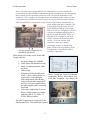
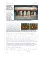
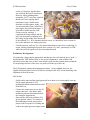
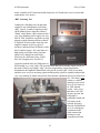
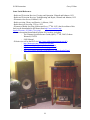
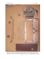
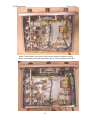
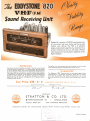
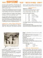
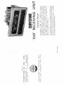
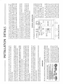
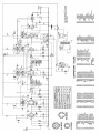
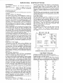
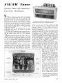
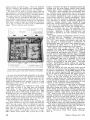
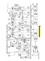
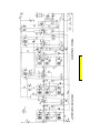
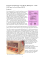
Restoration of an Eddystone’s ‘One and Only HiFi Separate’ – Model
S.820 Tuner - by Gerry O’Hara, G8GUH
Background
When I joined the EUG, Graeme Wormald sent me several
issues of Lighthouse and a copy of the excellent Quick
Reference Guide (QRG), 2nd Edition as part of my ‘hazing’
(this document can now be downloaded from the EUG web
site). While browsing this very commendable tome
authored by Graeme, I noticed what I thought was a bit of
an oddity on page 34 under the section entitled ‘The Small
Valved Eddystones’: first up under that section was
‘Eddystone Type S.820 1955-58. Broadcast HiFi FM
Tuner…’ I was quite intrigued. Eddystone made a HiFi
tuner? – that was news to me, and I wondered why they did
so – this being an apparently significant departure in
direction, even in the 1950’s when Eddystone had a retail
outlet (‘Webb’s Radio’ located at 14, Soho Street, London,
W1) and their business model included manufacturing sets for the radio amateur and
domestic short wave listener market as well as for professional and military applications.
The S.820 was noted to cover the (then) FM Band from 87.5 -100MHz (mono) plus one
‘Long Wave’ and two ‘Medium Wave’ (Broadcast Band) channels as presets. The EUG
description goes on to note that the tuner was supplied without a case, it being meant for
custom mounting in a ‘HiFi’ console, as was in vogue at the time. The model reportedly
had a production run of only 1000 units and cost some £38 (including a monstrous £9.50
‘purchase tax’ – see later): not an insignificant sum in 1955. The model sported a tuning
mechanism based on the famous Model No. 898 dial sold by Eddystone as a DIY item to
radio constructors (which alone I have seen raise over £50 on EBay), and was an 8 valve
circuit complete with its own mains power supply. My appetite was wetted and I decided
that I had to have one when the opportunity arose – it looked cute, was an oddity in the
Eddystones line-up and I was curious as to what one would sound like when played
through a reasonable sound system.
Besides, it would make a nice set to
provide background music while
working in my shack…
A couple of years went by –
monitoring EBay and locating all the
S.820 references in the EUG
Newsletter and the Lighthouse
magazine – and then an S.820 finally
came up for auction in Washington
DC, USA (good for me – less
The S.820 on arrival – not bad at first glance
1
S.820 Restoration
Gerry O’Hara
shipping charges than from the UK to my home in the Vancouver area, Canada). It
looked in reasonable shape in the advert: a few valve screens missing but otherwise good.
So I bid and was amazed to pick it up for only $43 (about £21).
A couple of weeks later it duly arrived in British
Columbia, very well packed, and complete with an
original leaflet and instruction manual. The leaflet
(scan appended to this article) has both the price and
the amount of tax payable printed on it as well as a
hand-written price scribbled on the back – looks like
the wily purchaser managed to negotiate a decent
discount from Webb’s…? My set is Serial No.
FG0020, which dates it as being manufactured in
June 1955, and this date ties in with the May 1955
date marked on the can of the smoothing capacitor.
Looks like mine is a very early model – so early that
the folks at the Bathtub seem to have forgotten to
indicate the model number on the rear of the tuning
dial as shown on the illustration in the QRG, the
leaflet and the instruction book.
During my two year gestation period I started to look at the evolution of HiFi following
WWII, albeit with only a passing interest, but in my younger days I was always in awe of
audio equipment manufactured by British manufacturers like Quad and Leak – it just
looked right, was solid, well-made and they tended to have neat and well thought-out
wiring (just like most Eddystones) – I recall servicing a Leak amplifier in my days at
Mysons in Carlisle in the early 1970’s and being impressed by the neat wiring. I will not
digress too much on this topic, but the following section compares the S.820 with a
couple of its contemporaries and a few web links are provided at the end of this article if
anyone is interested in taking more of a look. What I did note was that some of the
equipment manufactured by those names in the 1950’s can command very high prices
these days – for example a (mono) Quad II power amp can top $1,000. So why did
Eddystone decide to manufacture a HiFi tuner? and what was the market the S.820 was
launched into like? How sophisticated were HiFi set-ups at the time? and, in particular,
what was the status of quality radio reception in the UK in the 1950’s? So I thought that
it would be interesting to take a brief look at the market the S.820 was entering, including
a peek at some of its competition and/or peers before I go on to describe bringing my set
back to a serviceable and cosmetically good condition.
Context of the S.820
So why introduce an FM tuner into the Eddystone range in mid-1955? I would say that it
was because there was a great (apparent) opportunity opening up due to the BBC
introducing new services in the UK and the ‘HiFi’ bug was just catching on: more and
more homes were acquiring radio and audio equipment that was capable of providing
very good quality reproduction and there was a fledgling ‘high-end’ market developing
2
S.820 Restoration
Gerry O’Hara
Status of FM Broadcasting in the UK During the 1950’s
for the more ‘well-heeled’ listener. The
sidebar to the right provides some
interesting background details of the status
of FM broadcasting in 1950’s Britain for the
interested reader1.
And what was some of the competition like?
In the UK, the ‘Leak’ brand of HiFi
equipment had launched their ‘Trough-Line’
(MkI) tuner around the same time (1955) as
the S.820 made its debut. The TroughLine’s main design/selling feature was a
very stable oscillator circuit using a tapped
transmission line formed by a metal trough
surrounding the resonant element. This unit
was also supplied without a case, being
meant for inclusion in a console. A good
description of this unit appeared in a
The first of the BBC's new Band II VHF FM radio
transmissions started on May 2nd 1955 from the new mast at
Wrotham, Kent. This new service brought high fidelity radio
to around 13 million potential listeners in London and the
South East from the Home 93.5 MHz, Light 89.1 MHz and
Third Programmes 91.3 MHz. The FM mode of transmission
was broadcast on VHF frequencies between 88.0 MHz and
95.0 MHz and was less susceptible to the types of
interference often encountered on medium and long waves
which used the AM mode of transmission. This fact coupled
with the ability to use a higher bandwidth which could
provide ‘Hi-Fi’ quality transmission and reception enabled
the BBC to offer the then three radio services, Home, Light
and Third with audio quality never before experienced by
listeners. All transmissions were initially in mono however.
The BBC opened further high power VHF FM radio
transmitters in December 1955. For the West of England
and South Wales from the Wenvoe transmitter (120 kW) was
opened and transmissions for the North East from Pontop
Pike (60kW) commenced. In 1956 Sutton Coldfield
(Midlands - 120 kW), Holme Moss (North - 120 kW), North
Hessary Tor (South West - 60 kW), Tacolneston (East - 120
kW), Kirk O' Shotts (Central Scotland - 120 kW), Meldrum
(North East Scotland - 60 kW) and Divis (Northern Ireland 60 kW) followed. A transmitter at BlaenPlwyf (60 kW) was
also installed to bring reception to the Cardigan Bay area
along with a temporary transmitter in the Anglesey area
where reception on the Welsh Home service was particularly
poor.
More high power main-stations were soon introduced
followed by many low power relay stations that filled in some
significant pockets of poor reception [hence Eddystone
hedging their bets by including some pre-set AM capability
Above; an early Leak Troughto allow users to tune in to their favourite programs in this
Line FM tuner with the pressed
mode until they became available on VHF FM], and in
steel front, dating between
January, 1958 the BBC commenced experimental stereo
1955 and 1959.
transmissions on VHF FM in the London area. In the USA,
radio station WGFM in Schenectady, New York and station
contemporary issue of "HiFi News":
WEFM Chicago were transmitting the first regular
programmes in FM stereo in June 1961 using the Zenith GE
“Leak have adapted for their oscillator, Pilot Tone System and the BBC commenced permanent VHF
FM stereo radio broadcasting of the Third Programme in
a variation on the quarter-wavelength
line type of resonator. It has been found August 1962 from the Wrotham transmitter using the same
technology on 91.3 MHz. Stereo broadcasting was very
in communications engineering that for
gradually rolled out across the BBC's network of VHF
frequencies in the 100Mc/s region and
transmitters and national radio stations from the 1960's until
the 1980's.
1
Edited excerpt from ’UK Radio – A Brief History Part 2, Post War’ on Mike Smith’s very informative site
http://www.arar93.dsl.pipex.com/mds975/Content/ukradio2.html
3
S.820 Restoration
Gerry O’Hara
above, it becomes increasingly difficult, for a multitude of reasons, to make the
conventional coil and condenser combination operate satisfactorily; the chief among
these reasons are the capacitance inherent in the coil, and the inductance in the
condenser. Now, a quarter-wavelength section of transmission line, shorted at one
end, behaves as a parallel resonant circuit of very high Q and electrically stability,
while the mechanical construction of such a device leads almost automatically to
great rigidity (and hence stability). The
Q being high, tapping down will still
permit adequate voltage at the output;
and as the coil is a straight piece of wire,
selection of optimum tapping points is
obviously much facilitated. Below is a
diagram of the resonator in the Leak
circuit, and also the bread and butter
version. It is clear that the Leak
resonator is not a true quarterwavelength section, its length being
under 6 inches, but its frequency in the
Trough-Line is controlled by added
Can you spot the Trough-line on
(variable) capacitance.”
this Mk1 Leak chassis?
Other details given in the review for the MkI
Trough-Line are:
•
•
•
•
•
•
Frequency Range: 88-100MHz.
Foster-Seeley discriminator circuit.
Magic eye tuning indicator, 2kHz
accuracy.
10lbs weight.
Self powered (like the Eddystone
S.820) – quite a selling feature as
it meant less of an installation
effort unlike many other British
tuners of the time that required HT
and LT power to be supplied from
the audio amplifier they were being
used with.
Valve/tube complement (8) was as
follows: EM81 (magic-eye tuning
indicator), EB 91, 2 x EF80, 3 x
ECF80, EZ80 (rectifier).
The MkI Trough-Line was replaced by the
MkII around 1958. This model had a quoted
4
Above: Trough-line versus conventional
components. Below: above chassis view
of the Mk1 Troughline – a bit flimsey eh?
S.820 Restoration
Gerry O’Hara
drift of 15kHz without its AFC switched
on and with the AFC circuit switched on
this was reduced to 3kHz drift (or approx
0.003%). The published specification for
the MkII Trough-Line includes the
following:
•
•
•
•
•
•
Frequency Range: 88-108 Mhz
(note the extended upper end of the
band from 100MHz to 108MHz).
2 microvolt sensitivity for full
limiting.
300 Ohms or 75 Ohms aerial input.
Cathode follower audio output.
Multiplex output for add-on stereo
decoder.
Valve/tube complement (7) was as follows: 2x ECF80/6BL8, ECC84/6CW7,
ECC85/6AQ8, EF80/6BX6, EM84/6FG6 (magic-eye tuning indicator), EZ80
(rectifier)
The MkII Trough-Line was originally issued as a mono unit, with provision for adding a
stereo de-multiplexer later. Subsequent models were also available with solid-state stereo
decoders. As in the Leak, no provision was made in this range for AM reception.
Build-quality of the Leak units seems to have been good, though they do look a bit
‘lightweight’ when compared with the Eddystone unit – mind you, most things do.
Another famous name in British
HiFi, Quad, also introduced their
‘FM Tuner’ (photo, left) around the
same time (referred to as the
‘FM1’, presumably to distinguish it
from the later ‘FMII). Although the
Quad FM Tuner did not cover the
AM bands (perhaps its name was a
bit of a give-away in this regard),
Quad also made a matching AMonly tuner for this specific purpose.
These units were not fitted with
their own power supplies, however, deriving their LT and HT supplies from the amplifier
units they were used with. They were therefore much lighter (less than half the weight of
the Eddystone and Leak tuners) and were built into ‘sleeker’ looking cases, although the
mechanical build quality cannot light a candle to that of the Eddystone (at least in my
book) being reminiscent of a cheapo ‘all-American 5’ chassis – refer to the photo, top of
next page. Even so, Quad’s cosmetic style is a design classic that I have to admire.
5
S.820 Restoration
Gerry O’Hara
Earlier Quad FM1's
were badged
'Acoustical', later
ones 'Quad'. Later
models included an
internal switch for
use of the Quad
stereo decoder.
The early Quad
tuner valve line-up
was 6BH6, 12AT7,
ECC81, 6BJ6,
6BH6, 6AU6,
6AL5/EB91,
12AX7/ECC83
(the 6AU6 was replaced by a 6BH6 at some point in the production cycle).
I have included circuit diagrams for the
Leak and Quad tuners in an Appendix to
this article for comparison to the S.820
circuit (also appended). The Quad tuner
circuit somewhat resembled the S.820 in
its FM configuration, apart from a novel
twin-light tuning indicator circuit in the
Quad (photos, right) and provision of an
output for connection of a stereo decoder, whereas the Leak’s circuit design was rather
more sophisticated for its day, featuring a cascode RF amplifier and a cathode-follower
AF stage, the use of the trough-line tuning element (incorporating a switchable AFC),
output for a stereo decoder and it used solid-state diodes in the discriminator circuit.
So why were only some 1000 S.820’s ever built in its three year production period lasting
from 1955 to 1958? and why did Eddystone not follow in the footsteps of Leak, Quad
and others in improving on their original offering, eg. adding features such as a cascode
RF stage, AFC, stereo decoder and the like? I don’t know, other than speculate that the
competition was too specialized and focused directly into that particular sector of the
electronics market place, where cosmetic appearances and ‘hype’ were almost as
important as the quality of the electronic performance. Also, perhaps the ‘classic’ 1950’s
Eddystone style of the S.820, adapted from their successful contemporary ranges of
communications receivers, did not ‘cut the mustard’ in living rooms where it was under
the fickle-eye of non-technical family members? - come on Bill, spill the beans…
A Look at the S.820 Circuit and Features
Wireless World published a review of the S.820 in their July, 1955 issue (copy appended
to this article) that included a very good description of the circuit. In essence, the circuit
comprises virtually ‘textbook’ building-blocks. In VHF (FM) Mode:
6
S.820 Restoration
•
•
•
•
•
•
•
•
Gerry O’Hara
The aerial is connected to a tuned-grid pentode (6AM6) RF Amplifier choke
capacitance coupled to the tuned-grid of
A dual-triode (12AT7), one half acting as a mixer, the other half as the local
oscillator at VHF, feeding to a double-tuned 10.7MHz IF transformer, the
secondary of which connects through the band-change switch to the tuned-grid of
the hexode section of
A triode-hexode (ECH42), which in this mode functions as the first IF amplifier
(the triode section of this valve being rendered inoperative in this mode), the
hexode anode couples through a second double-tuned 10.7MHz IF transformer to
the grid of
A pentode (6AM6) second IF amplifier coupling through a third double-tuned
10.7MHz IF transformer to the grid of
A pentode (6AM6) limiter, the anode circuit of which contains the primary of the
discriminator transformer, the secondary of which is connected to the anodes of
A dual-diode (6AL5) connected in a Foster-Seeley circuit, the output of which is
connected through a wafer of the waveband switch (here selecting the
discriminator output) to the audio output connector - a Belling-Lee coax
connector - via the volume control.
A ‘magic-eye’ (EM80) tuning indicator, the grid of which is connected to the
input of the limiter valve; and it is worth noting that
There is no automatic frequency control (AFC) circuitry fitted and the band
selector switch derives AGC from the limiter stage grid bias to control gain of
both IF amplifier valves in this mode.
And in the (pre-set) AM Mode:
•
•
•
•
The VHF RF amplifier and mixer oscillator are disconnected from the grid of the
hexode section of the triode-hexode (ECH42), this instead being connected to the
broadcast band (2 x MW and x LW) preset antenna tuned circuits via the band
change switch.
The triode section of the triode-hexode acts as the local oscillator, the output of
which is internally coupled to the hexode section of the ECH42 producing an IF
of 465KHz at its anode. A double-tuned 465KHz IF transformer is located in its
anode circuit (in series with the 10.7MHz IF transformer), passing the IF signal to
the grid of
The pentode (6AM6) IF amplifier, again having a double-tuned 465KHz IF
transformer in its anode circuit (also in series with the corresponding 10.7MHz IF
transformer).
The IF signal at the secondary of the second 465KHz IF transformer is
7
S.820 Restoration
•
Gerry O’Hara
demodulated by a GEX34 germanium diode and the resultant audio fed to the
audio output connector via the volume control; and
AGC is also derived from the GEX34, this being used to control gain of both the
mixer and the IF amplifier valve when the tuner is working in AM mode. The
‘magic-eye’ is inoperative on AM.
A simple full wave rectifier power supply with an EZ41 coupled to a resistancecapacitance filter is used to supply the 205v HT to the tuner.
Preliminary Inspection and Safety Checks
Out of the packaging, first impressions were that the set was
as it appeared on the EBay advert. Then I set it on the
bench and noticed it did not sit square, then I saw that the
flexible coupler between the tuning dial drive shaft and the
tuning capacitor gang was operating at a really wild angle
(photo, right) and was offset sideways – oh dear, I realized
that I now owned yet another ‘dropped Eddystone’ (refer to
my other articles for discussion on this issue). The quality
of the packing (double boxed with bubble wrap galore)
suggested that it was probably like that before shipping to
me. Oh well, what can I expect for $43? I decided that I
had to straighten the chassis out as a priority - enough at
least to allow the tuning shaft to align properly with the
capacitor gang. I also noticed that the screen retaining
collars on two of the valve bases were broken (one
completely loose) and that some of the screening cans were
missing when compared to the photo on the front of the
manual supplied with the radio.
But first though, I noticed that the
mains connector did not have a
ground wire and that there was no
fuse fitted. I also noted that there
was no 120v tap on the power
transformer, so I would need to
use an autotransformer unless I
replaced the transformer (which I
did not want to do). Feeling
uneasy about all of this, I
installed a fuseholder fitted with a
one amp fuse under the chassis
(photo, right) and replaced the
power cord with one that
included a ground wire,
8
S.820 Restoration
Gerry O’Hara
connecting the ground wire to the chassis ground point near the smoothing capacitor can.
You will see from the
photos that the quality
of the wiring is firstclass and is
comparable to that
found on
contemporary
Eddystone
professional-grade
communications
receivers (eg. 730/4),
with superlative
‘regimental’ wire
dressing and
component layout.
Front Panel Removal and Replacement
The S.820 utilizes a modified form of the
Eddystone catalogue No. 898 dial (example in
photo, right), this being mounted on the cast
aluminium front panel, which is in turn bolted to
the two chassis side-plates. The chassis itself is
grey-painted brass.
Removal of the front panel in this simplified form
of ‘traditional’ Eddystone construction is very
straightforward. Here is the recipe:
•
•
•
•
•
Remove the knobs (on my set the grub
screws stubbornly refused to move, so I poured a little WD-40 into the screwholes and left it there for a couple of hours. The screws loosened ok after that);
Carefully remove the finger-plate, clean with soapy water and store safely (the
finger plate was stuck onto the front panel casting with some tarry compound as it
is otherwise only secured by the volume control bushing nut);
Loosen two screws in the flexible coupler on the tuning gang shaft;
Remove the four 2BA bolts securing the chassis side plates to the front panel; and
Gently pull the front panel away from the chassis (photos, top of next page and on
page 11).
The next job is to dismantle the No. 898-type mechanism sufficient to allow cleaning and
lubrication, as well as access to the scale glass for cleaning:
9
S.820 Restoration
•
•
•
•
•
•
Gerry O’Hara
Place small pieces of masking tape
on the spool pulleys to retain the
drive cord in place (photo, above);
Remove the two pointer guide rails
by levering-off the retaining springs
from either end. This allows access
to;
Remove the two idler pulleys at each
end of the dial cord run. Also
remove the spring-loaded cord
tensioner pulley;
Remove the three screws securing the
No. 898 drive mechanism to the front
panel - be careful as each has a split
washer between the No. 898 gearbox
plate and the rear of the front panel –
don’t lose them;
Pull the gearbox away from the front
panel;
Unscrew the three remaining screws
securing the rear (brown) plate from
behind the dial glass, noting how the
two cheek plates are secured. Pull
the plate away, revealing the dial
glass; and
10
S.820 Restoration
•
Gerry O’Hara
Carefully remove the dial glass (it may be tacked in place using some of the black
tarry compound similar to that used for the fingerplate – mine was).
Take this opportunity to carefully clean the dial glass with luke-warm slightly soapy
water (even being extremely gentle, a few small flakes of the dial paint came away when
I was cleaning the slight nicotine grime off the inside of mine). Also clean the brown
rear plate and matching cheek plates. This is also a good time to clean hardened
oil/grease from the gearbox bearings and gears (photo, previous page) and to re-lubricate
with suitable grease (I used a sparing amount of Moly-grease). Clean the friction clutch
mechanism and ensure the drive plate is grease-free.
Re-assembly is simply a reversal of the above, taking care to ensure that the dial cord is
threaded as per the original (tip - take a few photos and/or sketch it before you start
dismantling for reference). Attachment of the pointer to the dial cord can be a bit fiddly
– refer to the photo, below, right to see how it is done.
While dismantled, I noticed that the
front panel on my set is slightly
warped (as well as the chassis
itself). Concerned that the
aluminium casting might fracture if
I attempted to straighten it, I
decided to leave it alone and
instead just try to straighten the
chassis. This was done by applying
‘strong-arm tactics’ – I managed to
straighten it sufficiently to allow
the tuning gang shaft to align
reasonably well with the No. 898
drive shaft (photo, right).
11
S.820 Restoration
Gerry O’Hara
Initial Clean-up and Power-on
The tuning capacitor gang is silver-plated and this was carefully cleaned with ‘Silvo’ to
improve its cosmetic appearance and the contacts then cleaned with De-Oxit and the ball
bearing re-packed with Moly-grease. The tuning pointer guide rails were lightly smeared
with Moly-grease, as was the bandchange switch indents. The contacts on the
bandswitch were carefully cleaned with De-Oxit and a squirt of this fluid was also
sprayed into the volume control.
A few continuity checks were undertaken with the new mains lead fitted – the on-off
switch (ganged with the volume control) seemed to work well and other checks seemed
ok, so I decided that it was time for initial power-on checks:
-
-
-
-
I removed all the valves, cleaned and checked them on my Precision valve tester –
they tested good to very good. I suspect that they may even be the original fitment as
they are all either Osram or Mullard, made in the UK (if that is the case, the tuner has
probably seen very little service in its 52 year lifetime – a bit like me…);
Checked the resistance measurement from HT to chassis – rather low, rising to only
around 2kohms after an initial dip to almost zero on the meter as the smoothing
capacitors charged up. I decided that I would re-form the power supply electrolytic
capacitors in-situ;
I attached an AC voltmeter across the power transformer HT secondary, coupled up
the power lead to my variac and gradually applied power. The voltmeter indicated
that the HT winding was good and so the LT windings were checked – also ok;
Switched off the power and re-installed the rectifier (EZ41). Connected a DC
voltmeter on its 300v range across the HT line and the chassis. Re-applied power
gradually using the variac and at around 60 volts AC applied to the transformer
primary, some DC voltage began to appear across the twin smoothing capacitors
(C65); the capacitors were re-formed over a couple of hours by slowly increasing the
applied AC voltage from the variac, monitoring the HT current draw (all valves still
removed except the rectifier) - increasing the voltage in stages, holding for up to 15
minutes and also switching off/on a couple of times at each stage. I increase the
applied voltage in
increments of 25v, up to
the full HT volts of
~205v DC. Leakage
current at the end of reforming exercise was
acceptably low on all
capacitors – impressive
for 52 year old units. I
noticed that the ‘magiceye’ had been left
plugged in and it was
glowing quite nicely
12
S.820 Restoration
-
-
-
-
Gerry O’Hara
(photo, bottom of previous page);
Undertook leakage checks on a few of the ‘TCC’ metal-can 0.01uf and 0.1uf tubular
paper HT and screen by-pass capacitors (C3, C7, C19, C26, C42, C43 and C55), and
AGC line capacitors (C27, C33, C46) – those tested appeared ok, so I decided to try
powering-up the set without replacing any;
Checked the HT smoothing resistor (R36) and a couple of the anode load resistors –
all seemed within tolerance, so I;
Re-installed the remaining valves, connected short aerials to the AM and FM aerial
connections and attached a (powered) computer speaker set to the AF output. Slowly
brought the set up on the variac over around 15 minutes, monitoring the HT voltage;
After about 29 seconds…nothing. I switched off quickly and started to investigate –
nothing obviously wrong, so I switch it back on, turning the amplified speaker
volume to maximum. I could hear hum and a slight hiss, controllable using the
volume control on the S.820. The set was switched to FM during these tests. I
switched to one of the AM positions – more noise appeared. I then tuned one of the
MW local oscillator pre-set capacitors and voila! - a station came in on 1410kHz.
Still nothing on FM though.
I did a few voltage checks using the table in the manual as a guide (I used a
homebrew 1000ohm/volt meter adapter that allows quick switching-in of the correct
range shunts – see the sidebar on page 13 of my S.750 restoration article) – the AM
section was fine, as was the RF amplifier in the VHF section, but there was no anode
voltage on the mixer (12AT7). The anode load resistor (R4) had checked out ok
13
S.820 Restoration
-
Gerry O’Hara
earlier, so I began to fear that there
was a fault in the first IF transformer.
However, while prodding about
around the 12AT7 valve base I noticed
that the stiff wire coupling the IF
transformer to pin 1 had become
detached (circled in photo, right) – this
was not noticeable when viewed from
most angles, the joint looked intact. A
quick dab of solder later the VHF
section was also working! I
completed checking voltages and the
only real discrepancy remaining was
the voltage on the anode of the triode section of the EM80 ‘magic-eye’ (39v instead
of the indicted 27v). R34 (1mohm) checked out ok, so I decided to leave it alone for
now as the indicator was working correctly.
I left the tuner on ‘soak test’ for a few hours and nothing seemed to be overheating. It
stayed working ok during this period, but it seemed very ‘deaf’, particularly on VHF,
where the received signals were also somewhat distorted.
Preliminary Re-Alignment
Given that the voltage checks appeared ok and that the valves all checked out as ‘good’, I
decided that the VHF deafness may be due to poor alignment (a ‘mad twiddler’ had
obviously been at the cores as there were tell-tale signs of minor scratch marks around the
IF can openings and one of the cores was partly out of the top of the can).
The S.820 manual contains the alignment procedure – pretty standard, however, the
slightly different method I used is as follows, which prevents AGC action interfering with
alignment of the AM section:
AM Section
-
-
-
Switch on the tuner and the signal generator for an hour or so to thoroughly warm up.
Set the signal generator to 30%
modulation and the attenuator backed off
about half way;
Connect the output meter across the AF
output connector – this allows audio
monitoring when needed/wanted while
also using the output meter;
Short out the AM local oscillator (LO)
grid to ground, where C32 connects to
the bandchange switch, using a short
jumper lead to stop the LO working and
connect the signal generator output to the
14
S.820 Restoration
-
-
-
-
-
Gerry O’Hara
grid of the mixer valve, V3;
Short out the AGC line to ground to maximize gain;
Set the signal generator to 465KHz for the IF alignment. If you notice multiple peaks,
select the strongest one (it should be near the nominal IF of 465kHz). Connect the
signal generator output to the grid of the frequency changer (pin 1). Peak the cores of
T1 and T2. Repeat at least once as some of the adjustments may interfere with each
other, gradually backing off the applied signal using the attenuator on the signal
generator as needed to provide a reasonable output meter reading;
Once no further improvement can be attained, remove the shorts from the LO
capacitor and AGC line and remove the signal generator lead from the grid of the
mixer valve;
Connect a 330ohm ¼W resistor across the aerial connector (one connection post
earthed) and the signal generator to the non-earth end via a 0.0001uf capacitor;
Follow the alignment procedure for each of the three AM pre-sets as per the manual –
I used a VTVM monitoring the AGC line voltage to peak tuning on the desired
station;
One of the LO coil slugs was broken in my set – I slowly coaxed it out of the former
(took half an hour) cleaned out the broken parts, this being the upper section where
the slot in the slug had been subject to stress, probably as a result of someone forcing
it using an incorrectly sized tool, and replaced it the other way around, so the good
slot end was facing upwards, placing a little Rocol Kilopoise on the slug.
Hey presto, the AM section is done. Now for VHF mode.
VHF Section
-
-
-
Switch to VHF;
Disconnect the earthy end of R27 at the limiter
valve grid and insert a 50uA meter in series with
the disconnected end and ground. This acts as a
tuning indicator for this part of the alignment
procedure;
Follow the 10.7mHz IF, RF and Discriminator
alignment as per the manual – I found that this
procedure works very well.
Reconnect R27 to ground.
Hey presto, the FM section is also done.
More Clean-up and Mechanical Work
The chassis as received was rather ‘grubby’. I tried my usual rubbing alcohol and lighter
fluid solvents to no avail. After some experimentation, I found that a strong washing-up
liquid/water solution worked much better to remove whatever was covering the paint. I
then used ‘Brasso’ to polish up the black finish on the power transformer shroud,
cleaned-up each valve envelope and applied De-Oxit to the valve pins/sockets. I also
repaired the two valve base screen retaining collars by gluing with a carefully-placed
small dab of ‘JB Weld’ – a steel-strengthened epoxy-based glue designed for joining
15
S.820 Restoration
Gerry O’Hara
metal, available in DIY and some hobby shops here in Canada (this was a lot easier than
replacing the valve bases).
‘HiFi’ Listening Test
I undertook a listening test with the tuner
coupled to my (unfortunately solid state)
‘HiFi’ system - actually a homebrew dual
100W/channel power amplifier (labeled
‘Krank’ on the photo, right) constructed in a
very large Kingston power supply case way
back in 1986, coupled to a separate op-amp
preamp scratch-constructed from an article
in Practical Wireless at the same time, the
amplifier outputs are fed to a pair of
speakers constructed from Wilmslow audio
kits of similar vintage. My usual tuner is a
high-quality solid state stereo Akai unit
(photo, left), dating from mid-1990’s
(picked up in a Salvation Army ‘Thrift’
store for a bargain price of just $15).
Compared with the Akai, the Eddystone on
FM sounded very ‘crisp’ with a full, powerful base and lots of presence on the vocals, to
the point of being very slightly ‘edgy’ on some programming, suggesting that the
discriminator de-emphasis characteristics may not be exactly right. Noise levels (hum
and hiss) were very low on strong signals and the quality is quite acceptable and provides
very easy-listening (I double-checked the discriminator adjustment and it was found to be
ok). The tuner is very
sensitive, with full
quieting on just a foot
or so of wire stuck in
its VHF antenna
socket. Also, given
that there is no AFC
circuitry present, the
Eddystone is
remarkably stable and
sits firmly on the
selected frequency
after the first half hour
or so of warming-up –
a testament to the
solid construction
techniques used,
component selection
16
S.820 Restoration
Gerry O’Hara
and design of the oscillator circuit. The AM reception is also good, though obviously the
sound quality is not in the same league as on FM.
Conclusion
The Eddystone S.820 is quite a remarkable performer considering the limitations of its
relatively simple circuitry. It relies mainly on quality components and strong mechanical
construction to achieve adequate stability on VHF rather than innovative design. It’s
really outstanding features are the lovely smooth tuning controls – an Eddystone hallmark
of course, and its very good sensitivity on VHF (mine closes the ‘magic-eye’ on a foot of
wire in my basement workshop on several stations) – being able to operate well in
marginal signal areas was a definite advantage in the early days of FM broadcasting and a
therefore a good marketing feature. A limitation of the tuner in today’s FM band is that
it only tunes to 101.5 MHz if the dial calibration is used when aligning.
It’s a very cute little set though and well worth the effort to acquire one and restore it to
fully working condition. I will probably be using my S.820 mostly in my workshop to
provide background music rather than connected to my ‘HiFi’ system as a ‘retro
component’, though I am considering making a case for the set along the lines of one
from an S.870 so the chassis does not become a dust-collector… that will be the subject
of another article though. I would also note that one of my friends owns a high-quality
valve-based HiFi amplifier set-up and he is interested in trying out the S.820 also – it will
be interesting to see what the sound is like through such a system.
73’s
© Gerry O’Hara, G8GUH ([email protected]), Vancouver, BC, Canada, October,
2007
17
S.820 Restoration
Gerry O’Hara
Some Useful References
- Radio and Television Receiver Circuitry and Operation, Ghirardi and Johnson, 1951
- Radio and Television Receiver Troublshooting and Repair, Ghirardi and Johnson, 1952
- Electronics One-Seven, H Mileaf, 1967
- Radio servicing: Theory and Practice, A Marcus, 1948
- Radio Receiver Servicing, JT Frye, 1955
- Elements of Radio Servicing, Marcus and Levy, 2nd Ed. 1955, (the first edition of this
book can be downloaded in pdf format from http://www.archive.org/
details/Elements_Of_Radio_Servicing)
- Various documents downloaded from the EUG website, including:
- The Ultimate Quick Reference Guide (QRG), 2nd Ed., 2005, Graham
Wormald, G3GGL
- S.820 Manual
- Websites (as well as the EUG site http://www.eddystoneusergroup.org.uk/):
- http://home.mira.net/~kiewavly/Leak.html
- http://www.blackwidowaudio.com/index.htm
- http://www.collectableaudio.com/page11.html
- http://www.arar93.dsl.pipex.com/mds975/Content/ukradio2.html
18
S.820 Restoration
Gerry O’Hara
Above: The completely disassembled front panel and No. 898 drive parts (I did not take the
gearbox apart as it was working fine and only needed the removal of gummy grease and relubrication. Note the lack of any S.820 identification on the rear scale plate (bottom of photo)
19
S.820 Restoration
Gerry O’Hara
Above: Notice the slightly warped front panel casting – discussed in the text. Below left: yes,
I finally invested in some BA nut runners. Below right: The tuning capacitor gang after being
‘Silvo’d’. Note the glass bead forming the rear shaft bearing (bottom of photo)
20
S.820 Restoration
Gerry O’Hara
Above: Under-chassis view before safety improvements to the power supply.
Below: after fitting a fuse and replacing the power cord with a three-core cable
21
S.820 Restoration
Gerry O’Hara
Above: Under-chassis view with the cover plate in place. Below, rear chassis view –
note the ‘one-size fits all’ connectors (all horrid little Belling-Lees) – ‘wot, no phonos?
22
V10
Leak Mk1 Trough-Line
Tuner Circuit
Quad FM1 Tuner Circuit
Quad AMII Circuit Diagram