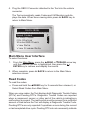
1
CP9575 Actron AutoScanner OBD II Scan Tool ® Safety Precautions This User’s Manual describes the features of the Tool and provides step-by-step instructions for operating the Tool. Always refer to and follow safety messages and test procedures provided by the manufacturer of the vehicle and the Tool. Read the User’s Manual completely before operating the Tool. An undetected or uncorrected vehicle malfunction could cause a serious, even fatal, accident. Important Safety Information in the User’s Manual is intended to protect the user, bystanders and the user’s vehicle. Signal Words Used Indicates a possible hazardous situation which, if not avoided, could result in death or serious injury to operator or bystanders. NOTICE Indicates a condition which may result in lost information. ⇒⇒ Indicates a single-step procedure. WARNING This Tool may not detect every malfunction. Do not take chances with brakes, steering, or other vital functions of your vehicle, as a serious accident could result. Important Safety Messages • Always wear ANSI approved goggles for eye protection. • Before testing a vehicle, make sure the transmission is in PARK (automatic transmission) or Neutral (manual transmission) and the parking brake is set. • Never lay tools on the vehicle battery. • Battery acid can burn. If contacted, rinse with water or neutralize with a mild base such as baking soda. If you splash your eyes, flush with water and call a physician immediately. • Never smoke or have open flames near vehicle. Vapors from gasoline and battery are explosive. • Do not use the Tool if internal circuitry has been exposed to moisture. Internal shorts could cause a fire and damage the Vehicle or Tool. • Always turn the ignition key OFF when connecting or disconnecting electrical components, unless otherwise instructed. • Most vehicles are equipped with air bags. If you elect to work around air bag components or wiring, follow your vehicle service manual cautions. You could be seriously injured or killed by an unintended deployment. The air bag can still open several minutes after ignition is turned off. • Always follow vehicle manufacturer’s warnings, cautions, and service procedures. About the Tool The Tool allows you to retrieve and erase/reset diagnostic data from the vehicle control module. The diagnostic data can be used to help determine the cause of a vehicle malfunction. Use the Tool to perform the following functions: Codes/Data Erase/Reset Retrieve Erase View Data -- MIL Status -- I/M Monitors Reset Freeze Data Erase -- State OBD Check Erase Drive Cycle Mode Reset Diagnostic Codes / Pending DTCs Vehicle Information Tool Parts LCD Display 8 line by 21 character monochrome backlit LCD. READ key Performs the Read Codes function and scrolls back through the screens. Press this key when an up arrow () appears on the display. Performs the Erase Codes function and scrolls forward through the screens. Press this key when a down arrow () appears on the display. ERASE key ENTER key Selects displayed items. BACK key Returns to the Main Menu or previous screen. OBD II Connector Connects the Tool to the vehicle connector. Icons The following icons may appear on the display: Indicates additional information is available on next screen by using the ERASE key. Indicates additional information is available on previous screen by using the READ key. Indicates a Pending DTC. # of # Appears only when viewing codes. Indicates code sequence and quantity (code # of n). For example, if you see 2 of 9 you are looking at the 2nd of 9 codes reported by the computer module. Mod $## Appears only when viewing codes. Indicates the computer module that reported the code. Indicates that the READ and ERASE hot keys are active. Connect the Tool To connect the Tool to the vehicle: 1. Locate the OBD II connector under the steering column. If the connector is not there, a label should be there indicating the whereabouts of the connector. 2. If necessary, remove the cover from the vehicle connector. 3. Turn the ignition switch to the ON position. Do not start the engine. 4. Plug the OBD II Connector attached to the Tool into the vehicle connector. The Tool automatically reads Codes and I/M Monitors and displays the data. When done viewing data, press BACK key to return to Main Menu. MAIN MENU ==================== Read Codes Erase Codes MIL Status State OBD Check View Data View Freeze Data ^^ Main Menu User Interface To select functions: 1. From the Main Menu, press the READ or ERASE arrow key until the desired function is highlighted, then press the ENTER key to retrieve and display the results. 2. When complete, press BACK to return to the Main Menu selection screen. Read Codes To read the codes: ⇒⇒ Press and hold the READ key for 2 seconds then release it, or Select Read Codes from Main Menu. When you view codes, the Tool displays both Diagnostic Trouble Codes (DTCs) and Pending DTCs. Diagnostic Trouble Codes are reported when a component, sensor, or other part of the vehicle is indicating a malfunction is present. The malfunction must be present for a sufficient amount of time before the Tool will display a Diagnostic Trouble Code. Pending DTCs are only reported if a problem occurs during the current or last completed drive cycle. Pending DTCs do not necessarily indicate a faulty component or system. Pending DTCs convert to Diagnostic Trouble Codes when an emissions problem persists long enough to be considered a real problem, not an anomaly. Pending DTCs are indicated by a icon. Vehicle Selection Vehicle Selection will be displayed for Read Codes when a manufacturer specific DTC is retrieved from the vehicle. Erase Codes The Erase function performs the following: 99 Erases Codes (both Diagnostic Trouble Codes and Pending DTCs) 99 May erase Freeze Data results depending on the vehcle. 99 Sets I/M Monitors to not ready. Perform Erase Codes function only after systems have been checked completely and DTCs have been written down. To erase codes from the vehicle computer: 1. Set the ignition to Key On and Engine Off. Do NOT start the vehicle. The engine should not be running. NOTICE 2. Press and hold the ERASE key for 3 seconds then release, or Select Erase Codes from Main Menu and press ENTER. 3. When the confirmation message appears on the display, choose one of the following options. • To proceed with the operation: Press ENTER for YES. • To cancel the operation and return to the Main Menu: Press BACK for NO. The Tool will automatically perform the Read Codes function after erasing codes. The Tool will then indicate the number of codes remaining. NOTICE If after erasing codes a DTC returns, the problem has not been fixed or other faults are present. MIL Status MIL (Malfunction Indicator Lamp) status indicates if the vehicle computer is telling the MIL to illuminate when the engine is running. • MIL ON indicates that the check Engine Light should be ON. • MIL OFF indicates that the Malfunction Indicator Lamp should be OFF. I/M Monitors Inspection / Maintenance Monitors provide a snapshot of the Emission System operations by indicating that the I/M Monitors are Ready or Not Ready. For an I/M Monitor to be Ready, the vehicle must have completed a drive cycle (been driven long enough under proper conditions to have completed a drive cycle). A Monitor must be listed as Ready to pass an emissions test. If an I/M Monitor is Not Ready, it is because a drive cycle has not completed. The Tool will indicate Ready (ok), Not Ready (inc), or Not Applicable (n/a) for each I/M Monitor. The Tool supports the following I/M Monitors: Monitors Expanded Name Misfire Monitor Misfire Monitor Fuel System Mon Fuel System Monitor Comprehen Comp Comprehensive Components Monitor Catalyst Mon Catalyst Monitor Htd Catalyst Heated Catalyst Monitor Evap System Mon Evaporative System Monitor Sec Air System Secondary Air System Monitor A/C Refrig Mon Air Conditioning Refrigerant Monitor Oxygen Sens Mon Oxygen Sensor Monitor Oxygen Sens Htr Oxygen Sensor Heater Monitor EGR System Mon Exhaust Gas Recirculation Monitor This is a complete list of I/M Monitors supported by the Tool. The number of Monitors read by the Tool from your vehicle may vary. A diesel vehicle, for example, does not have an Oxygen Sensor Monitor. As a result, there will be no Oxygen Sensor Monitor status for a diesel vehicle. Two types of I/M Monitors tests are: Since DTCs Cleared - shows status of the monitors since the DTCs were last erased. This Drive Cycle - shows status of monitors since the start of the current drive cycle. Refer to the vehicle service manual for more detailed information on emission-related monitors and their status. 99 Some vehicles do not support This Drive Cycle. If vehicle supports both types of monitors the I/M Monitors Menu displays. Drive Cycle Monitor The Drive Cycle Monitor function is very similar to the I/M Monitors though the Drive Cycle Monitor is used to view REAL TIME operations of the Emissions System on OBD II vehicles. 99 Drive Cycle Monitor continuously updates as the vehicle reports operations of the Emission System. 99 Refer to the vehicle service manual for how to perform a drive cycle on your specific vehicle. 99 Drive Cycle Monitor will only show the monitors that are inc (incomplete). When all monitors are complete the Tool will display a message. See I/M Monitors for more information. View Freeze Data Displays a snapshot of operating conditions at the time the Diagnostic Trouble Code was created. See PID Definitions for more information. Vehicle Information The Vehicle Information function allows the Tool to request the vehicle’s VIN number, calibration ID(s) which identifies software version in vehicle control module(s), calibration verification numbers (CVN(s)), and In-use Performance Tracking (IPT). Vehicle Information function applies to model year 2000 and newer OBD II compliant vehicles. NOTICE The Vehicle Information function is not supported by all vehicles. Also, not every vehicle supports every piece of information (for example, CVN, IPT, VIN). System Setup System Setup allows: • Display contrast to be changed, • Tool information to be viewed, • Display to be checked, • Operation of the keypad to be checked, • Memory of the Tool to be checked, • Language to be changed, • Units of measure to be changed. State OBD Check (Emissions) The State OBD Check function is used to display a basic status of the vehicle’s OBD system. The State OBD Check function has the following areas: MIL STATUS ON or OFF Number of Codes Found Number of Monitors OK Number of Monitors Inc Number of Monitors N/A 99 State OBD Check should be done with the key on engine running (KOER) due to showing MIL status. 99 The number of codes found are only DTCs and not Pending DTCs. 99 The number of Monitors that are either OK, INC or NA are only Since DTCs Cleared and not This Drive Cycle. 99 Refer to Read Codes and I/M Monitors for more detailed information about the results. View Data The View Data function allows real time viewing of the vehicle’s computer module’s PID data. As the computer monitors the vehicle, information is simultaneously transmitted to the Tool. View Data allows the following items to be viewed on the Tool: Sensor data Operation of switches Operation of solenoids Operation of relays Multiple PIDs may be sent if vehicle is equipped with more than one computer module (for example a powertrain control module [PCM] and a transmission control module [TCM]. The Tool identifies them by their identification names (ID) assigned by manufacturer Troubleshooting If a “LINK ERROR” message appears, cycle the ignition key to the OFF position for 10 seconds, then back ON, then press the ENTER key. Make sure the ignition key is in the ON n o t the ACCESSORY position. If the MIL Status is ON and the MIL is not illuminated with the engine running, then a problem exists in the MIL circuit. PID Definitions NOTE: The Tool only displays the PIDs the vehicle supports. Tool Description Tool Description ABS FRP Absolute Fuel Rail Pressure IGN ADV Ignition Advance ABS LOAD Absolute Load Value LT FTRM x Bank x Long Term Air To Fuel Ratio Correction Factor ABSLT TPS Absolute Throttle Position MAF Mass Air Flow Sensor ACC POS x Accelerator Position x MAP Manifold Absolute Pressure BARO PRS Barometric Pressure MIL DIST Distance Since Malfunction Indicator Lamp Came On CALC LOAD Calculated Engine Load MIL STATUS Malfunction Indicator Lamp Light Status CAT TEMP xy Catalytic Converter Temperature Bank x, Sensor y MIL TIM Time Since Malfunction Indicator Lamp Was Activated CLR DST Distance Since Codes Cleared O2S O2 Sensor Output CLR TIM Time Since Codes Cleared OBD2 STAT On Board Diagnostics 2 System Type CMD EQ RAT Commanded Equivalence Ratio OUTSID AIR Outside Air Temperature Tool Description Tool Description COOLANT Engine Coolant PTO STATUS Power Take Off Status EGR CMD Commanded Exhaust Gas Recirculation REL FRP Relative Fuel Rail Pressure or Vacuum EGR ERR Exhaust Gas Recirculation Error REL TPS Relative Or Learned Throttle Position ENG RUN Engine Run Time SECOND AIR Secondary Air Pump Status ENGINE Engine Speed ST FTRM Short Term Fuel Trim EQ RAT Oxygen Sensor Equivalence Ratio ST FTRM x Short Term Fuel Trim Bank x EVAP REQ Commanded Evaporative Emission System Purge THR POS x Throttle Position x EVAP VP Evaporative Emission System Vapor Pressure THROT CMD Throttle Actuator Commanded FUEL LVL Fuel Level TRIPS SNC CLR Warmups Since Erase Codes FUEL PRES Fuel System Pressure TROUB CODE DTC That Set Freeze Data FUEL SYS x Fuel System x Loop Status VEH SPEED Vehicle Speed IAT Intake Air Temperature VPWR Vehicle Power ACTRON HAND TOOLS