1
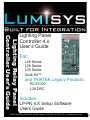
Lighting Relay Panel
Controller User’s Guide
Lighting Panel
Controller 4.x
User’s Guide
For:
L26 Series
L28 Series
L35 Series
Qwik-Kit™
and TRIATEK Legacy Products:
RCS1000
L28 DRC
Includes:
LP-PK 4.X Setup Software
Users Guide
1025 Cobb Place Blvd Suite 100 Kennesaw, GA 30144 • 800-241-9173 • www.lumisys1.com
Lighting Relay Panel
Controller User’s Guide
Attention
This section serves as a notice of the immediate or potential dangers involved when working with the
equipment described throughout this manual. Any person involved in installation, maintenance, or service
of the equipment should first carefully examine the equipment and read the instructions contained in this
manual to ensure that personal and/or equipment injury is avoided.
The following safety messages are used throughout this manual to alert of immediate or potential danger to
life or property:
Hint Indicates a tip or trick to help you.
Note Indicates a note related to one or more asteriks.
DANGER! Indicates an immediately hazardous situation which, if not avoided, will result in
death or serious injury.
WARNING! Indicates a potentially hazardous situation which, if not avoided, can result in
death or serious injury.
CAUTION: Indicates a potentially hazardous situation which, if not avoided, can result in minor or
moderate injury.
CAUTION: Used without the safety alert symbol, indicates a potentially hazardous situation which, if
not avoided, can result in personal or property damage. Failure to comply with proper handling of the
LUMISYS products may void your warranty
In addition, this symbol may appear in the margin of specific portions of text as a safety reminder. Applicable
instruction steps will be listed beneath the symbol.
Disclaimer
This equipment has been tested and found to comply with the limits for a Class A digital device, pursuant
to part 15 of the FCC Rules. These limits are designated to provide reasonable protection against harmful
interference when the equipment is operated in a commercial environment. This equipment generates, uses,
and can radiate radio frequency energy and, if not installed and used in accordance with the instruction
manual, may cause harmful interference to radio communications. Operation of this equipment in a
residential area is likely to cause harmful interference, in which case the user will be required to correct the
interference at his own expense.
Instructions contained in this user’s guide should be performed only by qualified persons in accordance
with local and national codes. LUMISYS® Lighting and its affiliates assume no responsibility for any
consequences related to the improper use of this manual.
www.lumisys1.com
Due to continuous product improvement, Lumisys reserves the right to change product specifications without notice.
Page Lighting Relay Panel
Controller User’s Guide
Table of Contents
LRP Controller User Guide Overvie
LRP Controller Hardware Features
Group, Output and System Status LEDs.............................. 5
Power, Communication and Watchdog LEDs....................... 6
Inputs ................................................................................. 6
Outputs ................................................................................. 7
Pushbuttons.......................................................................... 7
Power Supply Protection...................................................... 7
Network Terminals............................................................... 7
EPROM and EEPROM Diagnostics........................................ 7
LRP Controller Software Features
Number of Inputs.................................................................. 8
Timers Durations.................................................................. 8
Relay Refresh........................................................................ 8
Naming Inputs....................................................................... 8
Input Type............................................................................. 8
Analog Input ......................................................................... 9
Input Polarity........................................................................ 9
Assigning an Input ............................................................... 9
Output Flash......................................................................... 9
Maintained Input Priority...................................................... 9
View Current Input States.................................................... 9
Number of Relays/Outputs.................................................. 10
Group On-time After Flash.................................................. 10
Output/Relay Energize Time............................................... 10
Assigning Outputs/Circuits to a Group............................... 10
Naming Groups and Super Groups..................................... 10
Assigning Groups to Super Groups ................................... 10
Serial On Priority................................................................ 11
Check Bad Relays/Circuits ................................................ 11
Automatic Output Sequencing........................................... 11
Manual Override of Outputs............................................... 11
Return to Automatic control from Manual Override.......... 11
Setting or Viewing LRP Controller Network Address........ 11
LRP Controller Network Features
LRP Controller LP-PK Setup Software
Creating a LRP Controller Configuration Database........... 15
Overall Concept.................................................................. 15
Configuring Inputs.............................................................. 16
Number of Inputs................................................................ 16
Timers Durations................................................................ 16
Naming Inputs..................................................................... 17
Input Type........................................................................... 17
Input Polarity...................................................................... 18
Assigning an Input to Control an Output Group................ 18
Output Flash Warning......................................................... 19
Maintained Input Priority.................................................... 19
View Current Input States.................................................. 20
Configuring Outputs............................................................ 20
Number of Relays/Outputs.................................................. 20
Group On-time After Flash.................................................. 21
Group Flash Off-time.......................................................... 21
Output Refresh Time.......................................................... 21
Output/Relay Energize Time............................................... 21
Assigning Outputs/Circuits to a Group............................... 22
Naming Groups................................................................... 22
Assigning Groups to Super Groups ........................................... 23
Serial On Priority................................................................ 23
General LRP Controller Data
Check Bad Relays/Circuits................................................. 25
Setting LRP Controller Address......................................... 25
Communication and Device Status.................................... 25
Naming a LRP Controller.................................................... 26
Opening a File..................................................................... 26
Saving a File........................................................................ 27
Special Options
Read LRP Controller Database........................................... 28
Print LRP Controller Database........................................... 29
Troubleshooting the LRP Controller
Wake-Up LEDs..................................................................... 12
Resetting the LRP Controller............................................. 12
Pushbutton Mode Expiration.............................................. 12
Software Installation of LP-PK........................................... 13
Online LPPK Software Registration................................... 13
Connecting LP-PK to a single LRP Controller.................... 14
Connecting LP-PK to a LRP Controller through BASnet ... 14
Connecting LP-PK to multiple Controllers over Network.. 14
Configuring a database Online or Offline........................... 14
Outputs Will Not Turn On.................................................... 29
Controller not Communicating or Communication............ 30
System Status LED 2 not On.............................................. 30
Worksheets
Group Programming Schedule - Groups 01-30................... 31
Group Programming Schedule - Groups 31-60................... 32
Switch Input Programming Schedule................................. 33
www.lumisys1.com
Due to continuous product improvement, Lumisys reserves the right to change product specifications without notice.
Page Lighting Relay Panel
Controller User’s Guide
LRP Controller User Guide Overview
This user guide describes LUMISYS LRP Controller hardware and software features and how to configure these features
with LUMISYS’ LP-PK Windows based Setup Software.
LUMISYS’ Control Panels each contain an LRP Controller. The LRP Controller is a microprocessor-based controller that
provides the latest lighting control features to automate lighting control in a facility. Each LRP Controller provides for RS485 communication, input connections for external devices and outputs to drive its high voltage relays or circuit breakers.
Although each LRP Controller provides the same basic lighting control features there are slight differences between their
number of outputs, type of outputs, inputs and enclosures. TABLE 1 lists the hardware differences between each model. See
the respective data sheets and installation guides for specific information on each model.
TABLE 1
Model
Inputs
Outputs/Type
Lighting Relay Panels
L26 Series
L35 Series
L28 Series
120 max. + 1 Analog input
120 max. + 1 Analog input
16 max. + 6 Analog input*
1-60/GE RR9
1-60/LUMISYS TR1
1-8/GE RR7
Qwik-Kits
L2532-K
L2632-K
L2732-K
L2960-K
RCS-RM
16 max. + 6 Analog input*
120 max. + 1 Analog input
120 max. + 1 Analog input
120 max. + 1 Analog input
120 max. + 1 Analog input
120 max. + 1 Analog input
1-8/GE RR7
1-32/GE RR7
1-32/GE RR9
1-32/Douglas Relays
1-60/Touch-Plate Relays
1-60/Circuit breaker
Legacy Products
RCS1000
L2500
L28DRC
120 max. + 1 Analog input
120 max. + 1 Analog input
16 max. + 6 Analog input*
1-60/Circuit breaker
1-60/GE RR7
4 LTR
LUMISYS’ LP-PK Windows Setup Software is required in order to setup and commission LUMISYS control panels. It provides an easy way to set up each LUMISYS control panel and a means for saving the setup to a hard drive or diskette.
LUMISYS will factory program each LRP Controller from completed LP-PK Set Up Worksheets provided by the customer.
There is a slight fee for this service but it will be less than the cost of the customer trying to set up the LRP Controllers during
installation. Each LRP Controller can be factory addressed, tagged with the name of the electrical room where it will be
installed, and a copy of each .lpx file can be emailed to the customer. We highly recommend this service to minimize field
technician time. See the LP-PK Set Up Worksheets at the end of this manual.
The LP-PK software is a one-time purchase for a single site license. Each site must purchase its own software. Until further
notice all future LP-PK upgrades will be free to existing customers who can prove proof of purchase.
www.lumisys1.com
*Requires AI-6 Anolog Input Control Module.
Page Due to continuous product improvement, Lumisys reserves the right to change product specifications without notice.
Figure 1 is a picture of the LRP Controller used for Models L2500, L26 Series, L3500, RCS1000, L2532-Kit, L2632-Kit,
Lighting Relay Panel
Controller User’s Guide
LRP Controller Hardware Features
L2732-Kit, Figure 1 is a picture of the LRP Controller used for Models: L2532-K, L2632K, L2930-K, L2732-K, L35 Series,
L26 Series and TRIATEK Legacy Products: L2500 and RCS1000.
Figure 2 is a picture of the LRP Controller used for the L28 Series.
1
2
See Figure 1
3
1. Group Status
A description of each numbered
item is listed below.
4
17
6
3. System Status
5
14
17
8
7
13
13
18
12
2. Output Status
14
13
18
15
10
11
9
15
11
11
16
16
9
9
Figure 1
Figure 2
The difference between the two LRP Controllers is the number of inputs and outputs and the type of output device it controls
as listed in Table 1.
Group, Output and System Status LEDs
1. Group Status LED’s show the status of each of the LRP Controllers 60 lighting groups. The green LEDs labeled G1-G30
indicate output group status. If the associated LED is on then the group is on. If the LED is flashing, then the group is on
but in the Flash Warning mode and will automatically turn off after the On-Time After Flash has expired. In normal
operation, the AUTO (or BK) pushbutton is used to toggle the display between groups 1-30 and groups 31-60. System
Status LED 2 indicates which set of group status is being displayed. If Status LED 2 is off then groups 1-30 status are
being displayed and if Status LED 2 is on then groups 31-60 status are being displayed.
2. Output Status LED’s show the status of each of the LRP Controllers outputs. The L26 Series series and RCS-1000 use
outputs with auxiliary contacts so the associated red LEDs show the state based on the state of the outputs auxiliary
contact. Otherwise the output status LED will show the LRP Controllers commanded state of the output. If the LED is on
the output is on and if the LED is off its associated output is off.
www.lumisys1.com
Due to continuous product improvement, Lumisys reserves the right to change product specifications without notice.
Page Lighting Relay Panel
Controller User’s Guide
See Figure 1
3. System Status LED #1 (top, right) is the heartbeat of the LRP Controller. During normal operation
this LED should be flashing on and off. During programming mode it will be steady on. If this LED is
not flashing during normal operation then there is a potential problem with the LRP Controller. Please
see theTroubleshooting section of this guide.
4. The LRP Controllers will use STATUS LEDs 2-7 to display network communication information. This
is a great feature for technicians to quickly determine network status. The information displayed on
all LRP Controllers is as follows.
· STATUS LED 2 - Illuminates when any serial command is received.
· STATUS LED 3 - Illuminates when end of command character is received.
· STATUS LED 4 - Illuminates when this LRP Controller is addressed.
· STATUS LED 5 - Illuminates when a correct checksum is detected.
· STATUS LED 6 - Illuminates when this LRP Controller receives a legal command.
· STATUS LED 7 - Illuminates when the LRP Controller has executed a command.
5. LRP Controller L28 Series LED’s indicate either the state of each of its
eight outputs or the network communication information. When in the network
communication mode the LED’s represent the same information as shown
above for STATUS LEDs 2-7. Pressing the STAT Pushbutton will display network
communication information and pressing the AUTO Pushbutton will display the
status of its eight outputs. STATUS LED P on the L28 Series is the watchdog
timer and power indication, and 1-8 represent each of its outputs.
See Figure 2
See Figure 1
Power LED
Power, Communication and Watchdog LEDs
6. Power LED is steady on when the proper power is applied to the LRP Controller.
If this LED is not on please see the Troubleshooting section of this user guide
7. Communication TX LED illuminates if the LRP Controller is sending outbound
communication and the RX LED illuminates each time inbound communication
is received. If these LED’s are not operating please see the Troubleshooting
section of this user guide.
8. Watchdog LED should be steady on. If this LED is flashing or off please see
the Troubleshooting section of this guide
RX & TX
LEDs
Inputs
See Figure 1
Watchdog
LED
9. Input terminal blocks for connecting input wiring. The terminal blocks can be
removed from the LRP Controller for easy installation or for quick replacement of a
LRP Controller. 24 inputs standard, expandable to 120 inputs; 16 inputs
maximum for L28 Series.
10. Input expansion connector (Socket) provides connection of up to three optional thirty-two
Input expansion modules (See LEXP Data sheet) per LRP Controller for a total
www.lumisys1.com
Due to continuous product improvement, Lumisys reserves the right to change product specifications without notice.
Page Lighting Relay Panel
Controller User’s Guide
of 120 inputs. This is not available for the LRP Controller L28 Series.
11. Input Power jumper provides the capability to select the LRP Controller to power its inputs or allow an external
power source to power its inputs. Occupancy sensors that use 24VDC to power the sensor are typical
applications that are externally powering an input. Jumper in the “N” position configures the inputs to be dry
contact and powered by the LRP Controller. Jumper in the opposite position configures the inputs to be
externally powered by up to 24VDC. Each jumper affects only its respective eight inputs only. There is one
jumper for each of the LRP Controller’s eight inputs.
12. Analog Input terminal accepts a VDC signal up to a maximum of 6VDC or LUMISYS’ LS Series Light Sensors
Model LS Series /I-5V-0-5 for indoor level, LS Series /O-5V-0-5 for outdoor light level and LS Series /S-5V-0-5
for skylight levels.
Outputs
13. Output terminals to output devices. The LRP Controller provides cable headers for connection to its outputs.
See TABLE 1 for details on the output capability of each LRP Controller. A ribbon cable is used to connect the
LRP Controller output header to either a Relay Interface Board or Circuit Breaker Interface Board. Each output
driver on the LRP Controller is protected to survive a direct short which minimize failures.
14. On board current limiting is provided on all output drivers.
Pushbuttons
15. Three pushbuttons labeled “OVER” (or CH), “AUTO” (or BK) and “STAT” (or TG)
are provided on the LRP Controller to provide,
1) manually override of all the relays,
2) set the network address of the LRP Controller, and
3) view network status and group and relay status for more information on their use please refer to
the software features section of the user guide.
Power Supply Protection
16. Supply Power terminals for connection of 24VAC power. The terminal block can
be removed from the LRP Controller for easy installation or quick replacement of
an LRP Controller. The LRP Controller supply power protection circuitry provides
30VA self reset over-current protection.
Network Terminals
17. Network communication terminal blocks for connecting network. The terminal
blocks can be removed from the LRP Controller for easy installation or for quick
replacement of an LRP Controller. On-board isolation circuitry provides 500-volt
isolation for the RS-485 communication network.
EPROM and EEPROM Diagnostics
18. The LRP Controller continuously verifies integrity of its EPROM (Electrically Programmable-Read Only Memory)
and EEPROM (Electrically Erasable Programmable Read Only Memory). Unit will notify that an error exists through
the LP-PK Set Up software.
www.lumisys1.com
Due to continuous product improvement, Lumisys reserves the right to change product specifications without notice.
Page Lighting Relay Panel
Controller User’s Guide
LRP Controller Software Features
The LRP Controller software features listed in this user guide apply to the LUMISYS models running software version 4.0.
Number of Inputs
• 24 inputs standard per LP-Controller. (16 on L28 Series)
• Expandable to 120 inputs (16 maximum on L28 Series) with additional input expansion modules, part number LEXP.
• 1 analog input per LRP Controller. (Not available on L28 Series).
Timers Durations
•
•
•
•
Up to 3 timer values per LRP Controller.
Timers can be from 1 minute to 18 hours in length in 1-minute increments.
Timers can be assigned to any input. Timers must expire before an output can be commanded off.
Timers will automatically turn the output off after the timer has expired (or flash then turn output off if the flash warning
feature is selected).
• Input turns group on when activated but does not start timer until input is deactivated.
Relay Refresh
•
•
•
This provides the capability for the LRP Controller to refresh the status of each output to the correct state. The purpose
of this feature is to overcome power dips that may occur while output coils are being energized.
Refresh rate can be set to “0” for no refresh or refresh between 3 to 30 minutes in 1 minute increments. If you select 10
minutes then the LRP Controller will automatically pulse the output coil to the correct state every ten minutes.
This feature should only be used if you are experiencing problems with all outputs in a particular zone turning on or off
or if you know the power source to the LRP Controller drops below acceptable levels.
Naming Inputs
• Each input with the exception of the analog input can be named for identification purposes.
• Requires LP-PK 4.0, Input names are saved in the LP-PK .lpx file not in the LRP Controller.
Input Type
•
•
•
The LRP Controller provides six input types: Maintained, Momentary On, Momentary Off, Momentary On/Off,
Linked On and State Change.
Maintained inputs require the input be maintained to activate the output.
Momentary On inputs require a momentary closure to activate an output.
It requires a separate input be assigned as a Momentary Off input to deactivate the output.
Note If a timer is assigned to this input, the timer starts once the input is deactivated.
• Momentary Off inputs require a momentary closure to deactivate an output. It requires a separate input be assigned as
a Momentary On input to activate the output.
• Momentary On/Off inputs require a momentary closure to toggle the state of the output. This input type requires only
one input to perform both on and off control of an output. This input type requires the input device be in a location
where the lights are within visual contact.
Note If a timer is assigned to this input, the timer starts once the input is deactivated.
www.lumisys1.com
Due to continuous product improvement, Lumisys reserves the right to change product specifications without notice.
Page Lighting Relay Panel
Controller User’s Guide
•
•
Linked On inputs are designed for multi-level lighting control applications that require timers for automatic shutoff of
lighting. A typical application is 1/3, 2/3 and 3/3 lighting levels in conference room. One input is assigned to the 1/3
level output and a second input to the 2/3 level output. Typically two additional inputs are assigned as Momentary Off
inputs for the 1/3 and 2/3 outputs. Activating the 1/3 light level switch will turn on the respective output and begin its
timer. Once the timer has expired the 1/3 light level output will flash to warn the occupants that the lights are about to
turn off. Once the lights flash the two switches, 1/3 and 2/3, are linked as one so either the 1/3 or 2/3 switch can be
activated to reinitialize the timer for the 1/3 lighting level. Immediately after either switch is activated the switches are
automatically un-linked and return to their independent state until another flash warning occurs. Without this features a
user may accidentally activate the wrong level switch causing frustration for the user.
Change State inputs are designed for use with maintained 3-way switches in retrofit applications. A change of state will
toggle the state of the associated output.
Analog Input
• Each LRP Controller with the exception of the L28 Series Controller provides an input for accepting a 0-5 VDC signal
up to a maximum of 6 VDC for LUMISYS’ LS Series Light Sensors Model LS Series /I-5V-0-5 for indoor level,
LS Series /O-5V-0-5 for outdoor light level and LS Series /S-5V-0-5 for skylight levels.
Input Polarity
• Each input can be assigned either normally open or normally closed polarity.
Assigning an Input to control an Output Group
• Any input can control any output.
• Multiple inputs can control the same output.
• Some inputs have higher priority than others see “Input Types” for details.
Output Flash
•
•
Any output can be assigned to flash before turning off to warn the occupants that the lights will be turning off in the next
1-60 minutes. This feature is typically called Flash Warning.
Outputs can be assigned to turn off with no Flash Warning. Do not select Output Flash for HID lighting that require time
to restrike after turning off.
Maintained Input Priority
•
•
•
•
•
•
This feature provides the capability to set a hierarchy of exclusive control for maintained inputs that control an output.
The four priorities are None, Maintained ON, Maintained OFF and Maintained ON/OFF.
None Priority will provide no priority to the maintained input thus allowing
inputs or network commands to gain control of its associated output.
Maintained ON Priority will gain control of its assigned output and not allow any other input or network command to
turn its assigned output off.
Maintained OFF Priority will gain control of its assigned output and not allow any other input or network command to
turn its assigned output on.
Maintained ON/OFF Priority will gain control of its assigned output and not allow any other input or network command
to turn its assigned output on or off. This is the highest priority.
View Current Input States
• With the use of LP-PK software and laptop or PC, the status of all the LRP Controller inputs can be reviewed at any time.
• Momentary inputs will display their on status only for the duration of the momentary closure.
www.lumisys1.com
Due to continuous product improvement, Lumisys reserves the right to change product specifications without notice.
Page Lighting Relay Panel
Controller User’s Guide
Number of Relays/Outputs
•
•
•
This feature provides the capability to limit the number of outputs the LrP Controller will control.
This value can be between 1-60 outputs (8 for the L28 Series Controller).
The maximum number of outputs are determined by the LRP Controllers enclosure capacity and the number of outputs
installed in the enclosure
Group On-time After Flash
• Each output that is assigned to flash (see “Output Flash”) before automatically turning off will have an on-time after
flash value of 1-60 minutes in 1 second increments.
• All outputs use the same on-time after flash value per LRP Controller.
Output/Relay Energize Time
• The length of time the outputs coil is energized to change its state is programmable from .024 seconds to 1.56 seconds
in .012 second increments.
• This time is factory set for .072 seconds and typically should not be changed.
Assigning Outputs/Circuits to a Group
•
•
•
•
•
•
LUMISYS uses a control strategy that requires all outputs to be assigned to one or more groups. Control is
accomplished at the group level so each controlled output needs to be assigned to a group.
Each LRP Controller provides up to 60 groups
A group can include one output or many outputs up to the LRP Controller maximum. See table 1 for a listing of
LRP Controllers and their maximum output capacities.
If an application requires individual control of each output then assign each output to an individual group such as
output 1 to group 1, output 2 to group 2, etc. Many applications require multiple outputs to be turned on or off as a
group. Grouping eliminates the need to have a separate command for each output rather all of the groups outputs can
be controlled with one input or network command.
If groups share the same output then the shared output will not turn off until all its groups are commanded off. For
instance, a common area lighting circuit may be connected to output 1. If output 1 is assigned to both group 1 and 2
then both groups must be commanded off before the common area lighting will turn off. If group 1 and 2 are on and a
command is issued to turn off group 1, output 1 will remain on because group 2 is on.
Grouping is performed in the LRP Controller software so no hardwiring of outputs into groups is necessary.
Naming Groups and Super Groups
• Each group and Super Group can be named for identification purposes.
• Requires LP-PK 4.0, Group and Super Group names are saved in the LP-PK .lpx file not in the LRP Controller.
Assigning Groups to Super Groups
•
•
•
•
•
•
A Super Group is a logical grouping of 2 to 59 groups. The word super is used to differentiate between the two group
types.
Super Groups provide the capability to control multiple groups with one input or network command yet still allow
individual control of each group.
For example, Super Group 1 can contain groups 2-5. A network command can be issued to turn off Super Group
1, which will turn off groups 2-5. However, an input assigned to group 4 can turn on group 4 without affecting groups
2,3 or 5. Super Groups provides a high degree of flexibility.
A Super Group can contain any group but the Super Group number itself. Super Group 1 can contain any group but
group 1.
Super Groups contain two or more Groups.
Groups containing one or more outputs.
www.lumisys1.com
Due to continuous product improvement, Lumisys reserves the right to change product specifications without notice.
Page 10
Lighting Relay Panel
Controller User’s Guide
Serial On Priority
•
•
•
Serial On Priority provides the capability to assign a network command priority over a Momentary Off, Momentary
On/Off, Input Timer Duration, On-Time After Flash or Maintained Input with None selected for Maintained Input Priority.
Each Normal or Super Group has the option for Serial On Priority.
The only configuration that has higher priority than a Serial On Priority is a Maintained Input with Maintained Input
Priority set to ON, Off or On/Off. These input configurations will turn the group off even if a network command
with Serial On Priority has been issued.
• Any Input Timers or Groups in the flash warning mode will be overridden by a network command with Serial On Priority.
Check Bad Relays/Circuits
•
•
•
This feature will provide a list of outputs that might be misbehaving by not changing to the commanded state.
This feature is only available on the L26 Series and RCS1000 LRP Controllers because these outputs contain an
auxiliary switch to indicate the status of the output.
This feature can only be viewed through LP-PK.
Automatic Output Sequencing
• Each output in a group is sequenced rather than energizing all relays simultaneously.
• This minimizes large current draw typically required when energizing multiple outputs at once.
Manual Override of Outputs
•
•
•
•
Each LRP Controller provides a pushbutton which toggles the state of all its outputs. It does not execute any input or
network command while in Manual Override.
Press the pushbutton labeled OVER (or CH) (or ON for L28 Series) to override all outputs. Each time this pushbutton is
pressed all outputs will change state from on to off or off to on. You should hear the outputs change state
Any commands issued to the outputs during Manual Override will be stored in the LRP Controller so each output will
return to the last commanded state once the AUTO (or BK) pushbutton is pressed.
Manual Override mode will time-out in 10 minutes with no pushbutton button activity. Manual Override mode expiration
does not restore outputs to the last commanded state until AUTO (or BK) is pressed. Outputs will respond to new group
commands from network commands and inputs after the Manual Override mode has timed-out.
Return to Automatic control from Manual Override
•
•
Pressing AUTO (or BK) Pushbutton refreshes/restores the LRP Controller from OVERRIDE to NORMAL operation. All
outputs will return to their state prior to the OVER (or CH) pushbutton being pressed or to the stored state caused by a
command being received during manual override, so you may hear outputs changing state.
If the LRP Controller is not in Manual Override, pressing AUTO (or BK) toggles the view of the Group Status LEDs from
groups 1-30 to groups 31-60.
Setting or Viewing LRP Controller Network Address
•
•
•
•
The LRP Controller network address can be set between 1 and 255.
To set the LRP Controller network address press the AUTO (or BK) and STAT (OR TG) pushbuttons simultaneously.
Be sure to disconnect the network while setting the LRP Controller network address.
The LRP Controller address will be displayed on blinking STATUS LEDs 2-9 in
the upper right hand corner of the LRP Controller. Each LED is assigned the following binary value:
LED#
2
3
4
5
LED Value
1
2
4
8
LED#
6
7
8
9
LED Value
16
32
64
128
www.lumisys1.com
Due to continuous product improvement, Lumisys reserves the right to change product specifications without notice.
Page 11
Lighting Relay Panel
Controller User’s Guide
•
•
•
•
•
To determine the address of the LRP Controller add the value of LEDs 2-9 that are blinking. All LEDs blinking will repre
sent address 255.
To increment the address by one press the OVER (or CH) pushbutton.
Continue to increment until the desired network
address is displayed.
To decrement the address by one press the STAT (or TG) pushbutton.
Continue to decrement until the desired network address is displayed.
To save the network address to non-volatile memory, press the AUTO (or BK) pushbutton.
This will also return the LRP Controller to auto mode.
Failure to Press the AUTO (or BK) pushbutton will result in loss of network address after power failure because it will
not be saved to non-volatile memory.
Wake-Up LEDs
• After 10 minutes of no pushbutton activity the LEDs will enter an LED saver mode much like a screen saver mode on a PC.
• To wake up the LEDs press the STAT (or TG) pushbutton. The LED’s will illuminate to display group and output status.
Resetting the LRP Controller
•
•
•
The LRP Controller can be reset if you are experiencing abnormal behavior Resetting is the same as powering down
and powering back up the LRP Controller.
This will load the data saved in its non-volatile EEPROM into its RAM.
To reset the LRP Controller press the three pushbuttons OVER (or CH), AUTO (or BK) and STAT (or TG) simultaneously.
Pushbutton Mode Expiration
•
•
Override, Stat and address-set modes (as well as LED illumination) will time-out in 10 minutes with no pushbutton
button activity.
Mode expiration does not restore relays or save a new address until AUTO (or BK) is pressed. In the meantime how
ever, relays will respond to new serial commands and inputs.
LRP Controller Network Features
• Each LRP Controller is network ready for RS-485 with 500 volt isolation circuitry.
• Up to 255 LRP Controllers can be networked over a twisted pair of wires.
• LUMISYS LRP Controllers provides seamless integration with the following Building Automation Systems (BAS):
• Alerton Technologies via LUMISYS BACNET or Modbus E-Link
• Andover Controls via programmable port in their controller
• Automated Logic via LUMISYS BACNET E-Link
• BACNET via LUMISYS E-Link
• Delta Controls via LUMISYS BACNET E-Link
• Honeywell via LUMISYS BACNET or Modbus E-Link
• Johnson Controls Metasys via Direct Connect
• MODBUS via LUMISYS Modbus E-Link
• Siemens Building Technologies via Open Processor with LUMISYS driver
• Teletrol Systems via programmable port in their controller
• Trane Company via LUMISYS BACNET E-Link
• Others available, ask your LUMISYS System Provider for details.
• Pressing the STAT (or TG) Pushbutton displays the serial status on the L28 Series. Network Communications status
is always displayed on the non-L28 Series controllers. See the “Group Output and System Status LEDs” section in this
user guide that defines the significance of each STATUS LED.
www.lumisys1.com
Due to continuous product improvement, Lumisys reserves the right to change product specifications without notice.
Page 12
Lighting Relay Panel
Controller User’s Guide
Software Installation of LP-PK
1) For LP-PK versions 4.03 and higher, use the Uninstall utility to remove pervious versions of LP-PK.
2) From new CD or network browse to LP-PK4.03Distro/Setup.exe and open.
3) Follow the instructions and install LP-PK.
4) At the end of the installation process you may launch LP-PK or browse to LP-PK.exe and open. The product screen
appears (click “OK”), and then the Software Registration dialog box appears. (If the old version starts, check that no old
versions exist, especially in folders other than C:\Porgram Files\LUMISYS and delete manually if needed.)
5) The registration screen shows a six character Software Code and a space to enter the Activation code. Record the software code. The code is case-sensitive.
6) Obtain the Activation Code by emailing LUMISYS Technical Support or Customer Service during normal business hours.
You may also complete the process at any time by visiting the LUMISYS website. Refer to section “Online Software
Registration” below for instruction on how to register through the LUMISYS website.
Online LPPK Software Registration
1) Run LPPK. LPPK Software registration will appear.
2) Go to www.lumisys1.com. (or use this hyperlink)
a) Select the Product Button
b) Select LP-PK from the “Software & Protocol Devices” jump menu
c) Click the LP-PK online registration link and follow the instructions.
3) The LPPK Application Registration page will provide you with an executable file program that will launch the LPPK Key
Generator. Save the program or Open the program to run it immediately. The LPPK Key Generator screen will appear.
4) Copy the Software Code from the LPPK Software Registration screen (1)
and enter it into the “Controller Software Code”
field of the Key Generator screen (2).
5) Click the “Generate Key” button (3) and the liberation key (registration
key) will appear. Click in the “Generate File” check box if you want the
key to be generated and saved in a fi le. Copy the key (4), and enter that
key into the “Activation Code” field in the LPPK registration screen (5).
6) Click the Activate button (6), and the “Product Activated”
message box appears confirming successful activation. Click
“OK” to close the screen (7), and the LPPK connect screen
appears.
1
6
5
ABC123DOREYME|
2
4
|ABC123DOREYME
7
www.lumisys1.com
3
Due to continuous product improvement, Lumisys reserves the right to change product specifications without notice.
Page 13
Lighting Relay Panel
Controller User’s Guide
Connecting LP-PK to a single LRP Controller
1) Select the communication port connected to LRP Controller.
2) Enter address of LRP Controller and select “Read This Address”. LP-PK will try to establish communication with this LRP
Controller. If communication is established the LRP Controller address and it’s software version will be displayed. Or select
“Scan Address” if you don’t know the LRP Controller address
3) Click on OK to connect to LRP Controller and select OK when prompted to read LRP Controller database.
4) If communication is not established, verify you have correct address and communication port.
Connecting LP-PK to a LRP Controller through BASnet LightView
LUMISYS’ BASnet LightView (Legacy Product) allows users to program all LUMISYS panels connected to BASnet LightView
over the Internet from any location. The workstation must be running version LP-PK 4.02 and higher. When using LP-PK with
LightView, scheduled lighting events will still take place. During LP-PK programming activities via LightView, response times
on LP-PK may be noticeably slower, because LightView is being shared.
To use LP-PK via LightView:
1) Have the PC or Laptop connected to LightView as described in the “BASnet LightView User’s Guide 2.0” section
“Connecting to BLV”.
2) Start LP-PK and on connect screen, select radio button “Internet”.
3) Still on the Connect screen, enter the IP address for LightView in the box “Hostname”
4) Enter the Username and Password
5) Click the Connect button.
6) LightView will authenticate the connection
7) Continue normal programming with LP-PK.
Connecting LP-PK to multiple LRP Controllers over a Network
Note You will need an RS-232 to RS-485 converter on you PC or laptop to communicate to multiple
LRP Controllers. (LUMISYS part number LP-485-TO-232 or equivalent)
1) Select the communication port connected to LRP Controller.
2) Enter address of LRP Controller and select “Read This Address” or select “Scan Addresses”. LP-PK will try to establish
communication with this lighting control panel or scan addresses 1-255 and list all LRP Controller on this network.
3) Make sure the address of the LRP Controller is in the address box. Then click on OK to connect to LRP Controller, and
select OK when prompted to read LRP Controller database.
4) If communication is not established, verify you have correct communication port.
Configuring a database Online or Offline
A database can be configured while connected to a LRP Controller or offline. To configure a database while connected to a
LRP Controller follow the instructions to connect to a LRP Controller listed above then skip to step 4 below.
1) To configure a database offline select “Offline” as the Communication Port during start-up.
2) Select the desired LRP Controller address in the box labeled “Program for Address” and the type and software version to
be programmed offline in the box labeled “Program for Type”.
3) Select OK.
4) The database configuration screen will be displayed.
www.lumisys1.com
Due to continuous product improvement, Lumisys reserves the right to change product specifications without notice.
Page 14
Lighting Relay Panel
Controller User’s Guide
LRP Controller LP-PK Setup Software
Creating a LRP Controller Configuration Database
Overall Concept
The essential function of the set-up software is to assign inputs to outputs. Hardwired inputs and outputs are “soft wired” via
the “Output Group” in the set-up software. This essential concept is illustrated by the circle diagram below.
Inputs
Group
Outputs
Inputs are assigned to a Group on the main screen, “LP Programming Kit V4.0” shown below.
www.lumisys1.com
Due to continuous product improvement, Lumisys reserves the right to change product specifications without notice.
Page 15
Lighting Relay Panel
Controller User’s Guide
Outputs are assigned to that group on the “Group Set-Up” screen shown below.
Configuring Inputs
Number of Inputs
1) Select the number of inputs that will be utilized by typing in a number between 1 and 120 in the
box labeled “Inputs”. This number should match the input hardware provided with the
LRP Controller.
2) The L28 Series input maximum is 16.
3) To save this information to a file or to the LRP Controller see “General LRP Controller Data Save File and Write Database to LRP Controller”.
Timers Durations
1) Type in the duration of the timer (1 minute to 18 hours) in the boxes labeled
“Timer Durations 1, 2 and 3”. The first two places are for hours (hh) and the second two places for
minutes (mm). These timers will be activated by an input and will affect an output.
2) To save this information to a file or to the LRP Controller see “General LRP Controller Data
- Save File and Write Database to LRP Controller”.
www.lumisys1.com
Due to continuous product improvement, Lumisys reserves the right to change product specifications without notice.
Page 16
Lighting Relay Panel
Controller User’s Guide
Naming Inputs
1) Each input can have a name in addition to a number.
2) To automatically name the inputs as Input 1, Input 2, etc. go to the tool bar and select “Input/Create Default Name for All”
then select “As Input n”. Each input will be named according to its input number e.g. Input 1, Input 2, etc.
3) To automatically name the inputs with the name of the group it controls go to the tool bar and select “Input/Create Default
Name” for All then select “Copy Name From Assigned Group”. Each input will be named with the same name of the group
it controls.
4) To individually assign a name to an input type in the desired name of each input in the box labeled “Name” next to the
column labeled “Input #”.
5) Repeat step 4 for each switch input.
6) To save this information to a file or to the LRP Controller see “General LRP Controller Data - Save File and Write Database
to LRP Controller”.
Input Type
1) There are six input types: Maintained, Momentary On, Momentary Off, Momentary On/Off, Linked On and State Change.
See the LRP Controller Software section of this manual for a description of each input type.
2) To automatically assign all inputs to the same type go to the tool bar and select “Input/Set All As Type” then select the
desired type. All inputs will be assigned this type.
3) To individually assign input types select the input type in the box directly next to the input number labeled “Type”.
4) Repeat step 3 for each input.
5) To save this information to a file or to the LRP Controller see “General LRP Controller Data - Save File and Write Database
to LRP Controller”.
www.lumisys1.com
Due to continuous product improvement, Lumisys reserves the right to change product specifications without notice.
Page 17
Lighting Relay Panel
Controller User’s Guide
Input Polarity
1) Each input can be assigned a normally open or normally closed polarity.
2) To automatically assign all inputs to the same type go to the tool bar and select
Input/Set All As Type then select the desired type. All inputs will be assigned this type.
3) To save this information to a file or to the LRP Controller see “General LRP Controller Data - Save File and Write Database
to LRP Controller”.
Assigning an Input to Control an Output Group
1) Under the Column heading labeled “Assigned Group” select the name of the group the input
will be controlling. If you do not know the Group Name then type in or select the group number
between 1 and 60 under the column labeled “0..60”.
2) Repeat step 1 for all inputs.
3) To save this information to a file or to the LRP Controller see “General LRP Controller
Data - Save File and Write Database to LRP Controller”.
Assign a Timer to an Output Group
1) To automatically assign all inputs to the same timer go to the tool bar and select
“Input/Set All For Timer” then select the desired timer. All inputs will be assigned
to this timer.
2) To individually set timers, enter timer duration between 1 and 3 in the box labeled “Timer” or scroll down to the desired
timer. Entering 0 will deactivate the timer feature.
3) Repeat step 2 for all inputs.
4) To save this information to a file or to the LRP Controller see “General LRP Controller
Data - Save File and Write Database to LRP Controller”.
www.lumisys1.com
Due to continuous product improvement, Lumisys reserves the right to change product specifications without notice.
Page 18
Lighting Relay Panel
Controller User’s Guide
Output Flash Warning
1) To automatically assign all inputs to Flash or No Flash, go to the tool bar and select “Input/Set All For” then select Flash or
No Flash. All inputs will be assigned this selection.
2) To individually set Flash, click on the box labeled “Flash” to enable the flash before off feature. The input number is located
to the right of the box.
3) To deactivate the flash before off feature click on the check mark in the box.
4) Repeat step 2 or 3 for all inputs.
5) To save this information to a file or to the LRP Controller see “General LRP Controller Data - Save File and Write Database
to LRP Controller”.
Maintained Input Priority
1) Select the group that will be controlled by this maintained input. See the instructions titled “Assigning an Input to control an
Output Group”.
2) In the box titled “Maintained Input Priority” select either None, On, Off or On/Off.
3) To save this information to a file or to the LRP Controller see “General LRP Controller Data - Save File and Write Database
to LRP Controller”.
www.lumisys1.com
Due to continuous product improvement, Lumisys reserves the right to change product specifications without notice.
View Current Input States
Page 19
Lighting Relay Panel
Controller User’s Guide
1) From the toolbar select “Input”, then “View Current States”.
2) An Input Status screen will appear to continuously display input status for each input configured in the database. To set the
number of inputs in the LRP Controller database, see the instructions titled “Number of Inputs”.
3) The boxes and numbers represent the input numbers. An “X” in the box indicates the input is activated. Momentary inputs
will only display the “X” for the duration of the momentary closure.
4) The area labeled “Analog Input” allows you to select a value range from 0-255 with which LP-PK will dispay a value in
proportion to 0-5VDC analog input signal. Analog inputs 1-6 are for L28 Controllers with an AI-6 module. All other
controllers use only input 5. If there is no analog input connected the analog input value will display “0”. Input should be
limited to 6 VDC maximum; displayed values should be interpreted accordingly.
Configuring Outputs
Number of Relays/Outputs
1) Select the number of outputs that will be utilized by typing in a number between 1 and 60 in the box labeled “Outputs”.
This number should match the number of outputs to be controlled.
2) To save this information to a file
or to the LRP Controller see
“General LRP Controller Data
- Save File and Write Database to
LRP Controller”.
www.lumisys1.com
Due to continuous product improvement, Lumisys reserves the right to change product specifications without notice.
Page 20
Lighting Relay Panel
Controller User’s Guide
Group On-time After Flash
1) In the area labeled “Flash Durations” there is a box labeled “ On-Time After Flash”.
2) Set the length of time (in mm:ss). This will be the length of time the output will be on after the flash warning has occurred.
3) This value can be from 10 seconds to 60 minutes in one-second increments.
4) To save this information to a file or to the LRP Controller see “General LRP Controller Data - Save File and Write Database
to LRP Controller”.
Group Flash Off-time
1) In the area labeled “Flash Durations” there is a drop down box labeled “Flash Off Time”.
2) This value is factory set for .5 seconds.
3) To save this information to a file or to the LRP Controller see “General LRP Controller Data - Save File and Write Database
to LRP Controller”.
Output Refresh Time
1) In the area labeled “Relays” there is a drop down box labeled “Refresh Period.”
2) To set an output refresh rate select a time between 3-30 seconds from the drop
down box.
3) To deactivate this feature select OFF from the drop down box.
4) To save this information to a file or to the LRP Controller see “General LRP Controller
Data - Save File and Write Database to LRP Controller”.
Output/Relay Energize Time
1) In the area labeled “Relays” there is a drop down box labeled “Energize Duration”.
2) The output energize duration is factory set for 0.072 seconds. There should be no need to change this value.
3) To save this information to a file or to the LRP Controller see “General LRP Controller Data - Save File and Write Database
to LRP Controller”.
www.lumisys1.com
Due to continuous product improvement, Lumisys reserves the right to change product specifications without notice.
Page 21
Lighting Relay Panel
Controller User’s Guide
Assigning Outputs/Circuits to a Group
1) Under the column heading labeled “Assigned Group” select “Setup”. This can also be accomplished by selecting Group
from the toolbar then selecting “Setup”.
2) The Group Setup screen should appear.
3) Select the desired Group between 1-60, to be created or modified.
4) Once the Group number is selected, click on the box associated to the output/ relay number to be added to the group.
Select each respective box until all the desired outputs/relays are assigned to this group. There are buttons to the left
labeled “Add All” to add all relays to the group; “Remove All” to delete all from the group and “Invert” to select the outputs
that are not checked.
5) Repeat steps 3-4.
6) To save this information to a file or to the LRP Controller see “General LRP Controller Data - Save File and Write Database
to LRP Controller”.
Naming Groups
1) Under the column heading labeled “Assigned Group” select “Setup”. This can also be accomplished by selecting Group
from the toolbar then selecting “Setup”.
2) The Group Setup screen should appear.
3) Select the desired Group between 1-60, to be named.
4) In the box next to the Group number type up to 15 characters to name the output.
5) Repeat steps 3-4.
6) To save this information to a file see “General LRP Controller Data - Save File and Write Database to LRP Controller”.
These names are saved in the .lpx file so be sure to “Open Names” after opening the LRP Controller database.
www.lumisys1.com
Due to continuous product improvement, Lumisys reserves the right to change product specifications without notice.
Page 22
Lighting Relay Panel
Controller User’s Guide
Assigning Groups to Super Groups
1) Under the column heading labeled “Assigned Group” select “Setup”. This can also be accomplished by selecting Group
from the toolbar then selecting “Setup”.
2) The Group Setup screen should appear.
3) Select the desired Super Group number between 1-60, to be created or modified.
4) Once the Group number is selected, click on the circle in the “Group Type” area labeled “Super”. The numbers next to the
boxes represent the groups included in the Super group. The group that matches the Super group number will be grayed
out because it cannot be assigned to the Super group.
5) Select the desired groups to be included in the Super group by clicking the respective box.
6) Repeat steps 3-5 until all Super groups are defined.
7) To save this information to a file or to the LRP Controller see “General LRP Controller Data - Save File and Write Database
to LRP Controller”.
Serial On Priority
1) Under the column heading labeled “Assigned Group” select “Setup”. This can also be accomplished by selecting Group
from the toolbar then selecting “Setup”.
2) The Group Setup screen should appear.
3) To activate this feature click on the box in the lower left hand corner of the screen labeled “Serial On Priority”. An “X” will
appear in this box to indicate the feature is selected.
4) To deactivate this feature click on this box to remove the “X”.
5) To save this information to a file or to the LRP
Controller see “General LRP Controller Data - Save File
and Write Database to LRP Controller”.
www.lumisys1.com
Due to continuous product improvement, Lumisys reserves the right to change product specifications without notice.
Page 23
Lighting Relay Panel
Controller User’s Guide
View/Modify Current Output States
1) From the toolbar select “Group”, then “View/Modify Current States”.
2) A Group Status screen will appear and continuously display output status for each output configured in the database. To
set the number of outputs in the LRP Controller database, see the instructions titled “Number of Relays/Outputs”.
3) To check the status of a Group, mouse-click once with the mouse cursor on the desired Group status display. Text boxes
at the bottom of the screen will display status information and the current status of the group including what caused the
group to be in its current state.
4) To manually change the state of a Group, mouse-click twice on the Group status display. The State of the group will
change.
www.lumisys1.com
Due to continuous product improvement, Lumisys reserves the right to change product specifications without notice.
Page 24
Lighting Relay Panel
Controller User’s Guide
Check Bad Relays/Circuits
This feature provides the capability to display the relays which are not in the correct state.
1) From the toolbar select “Group”, and then select “Check For Bad Relays.
2) LP-PK will determine which relays are not in the correct state and will list them in a dialog screen.
These relays may be malfunctioning and need replacing. Resetting the relays will be required to clear this screen. If you
do not reset the bad relays then the same relay numbers will be displayed the next time you check bad relays. Be sure to
reset the bad relays by selecting YES. If you want to keep the Bad relay listing the next time you select this screen then
select NO.
General LRP Controller Data
Setting LRP Controller Address
1) Connect to LRP Controller.
2) Double click on the address box. The “Address Change” screen will appear.
3) Enter the new address and click ‘Change’.
4) To save this information to a file or to the LRP Controller see “General LRP Controller
Data - Save File and Write Database to LRP Controller”.
Communication and Device Status
Status
The Status box displays either on-line or off-line programming. If on-line is displayed then your computer is currently connected to a LRP Controller, which is not the case with off-line.
Port
Is not applicable with off-line programming. The computer serial port will be displayed in this box if you have selected on-line
programming.
www.lumisys1.com
Due to continuous product improvement, Lumisys reserves the right to change product specifications without notice.
Page 25
Lighting Relay Panel
Controller User’s Guide
Address
The address of the LRP Controller you selected in on-line or off-line setup.
EPROM
Displays the status of the LRP Controllers EPROM which contains the LRP Controllers software. This is not applicable for
off-line programming.
EEPROM
Displays the status of the LRP Controllers non-volatile EEPROM which contains the LRP Controller database. This is not
applicable for off-line programming.
Naming a LRP Controller
1) Select the blank text block above LRP Controller Address type in LRP Controller name up to 15 characters.
2) To save this information to a file or to the LRP Controller see “General LRP Controller
Data - Save File and Write Database to LRP Controller”.
3) All name information is saved in the .lpx file not in the LP-Controller.
Opening a File
1) Select the “File” drop down menu “Open” or “Open Names”.
2) “Open File” provides the capability to open a saved *.lpx file. The suffix “.lpx” is used for all LUMISYS LRP Controller files.
3) “Open Names” which reads all name data and displays it on screen.
4) Select the File you want to open.
5) Press “OK” to open the file..
www.lumisys1.com
Due to continuous product improvement, Lumisys reserves the right to change product specifications without notice.
Page 26
Lighting Relay Panel
Controller User’s Guide
Saving a File
1) Select the “File” drop down menu “Save”.
2) “Save File” provides the capability to save the current information as an “.lpx” file. The name can be up to eight characters in
length.
3) “File Description” provides the capability to describe the file such as “North Wing Electrical Closet" or "Fifth Floor Lighting",
etc. to further
explain or describe the file.
4) Press “OK” to save the file.
Special Options
1) Select “Other” drop down menu select “Special Options” Special Options appears.
2) “JC N2 Protocol Enabled” provides the capability to enable Johnson Controls N2 protocol. This option will need to be
enabled when networking the LRP Controller with Johnson Controls Metasys, Companion or Facilitator product lines. Click
on this box to enable the Johnson Controls N2 protocol.
3) “JC Override Auto Release” is for Johnson Controls N2 integration applications only. The Johnson Control N2 protocol will
release the lighting zone if communication is not detected within 10 minutes. Releasing the lighting zone could turn the lights on or
off depending on the Johnson Controls N2 command received by the LRP Controller prior to the release. Disable this feature if
you want the lights to stay in the current state when communication is lost.
4) Group 1 -> Timer 1; Group 2 -> Timer 2; Group 3 -> Timer 3:
This option provides the capability to alternate all switches in a panel with a timer from timer control to no timer control.
Examples are classrooms or offices that need a switch without a timer during the day and utilize the timer after hours. To
select this option click on the box next to the option. See the table below.
5) To save this information to a file or to the LRP Controller see “General LRP Controller Data - Save File and Write Database
to LRP Controller”.
WARNING! Be sure that Groups 1, 2 and 3 do not have relays assigned if these options are selected.
BAS Command
Switch Timer State
On Switch is pressed
Panel X, Group 1 On
All switches in Panel X with Timer 1 will respond as if there is no timer
Lights will stay on until command off
Panel X, Group 1 Off
All switches in Panel X with a Timer of 1 will now use Timer 1 when pressed
Lights will stay on for duration of Timer 1 then turn off or flash
if set for flash warning
Panel X, Group 2 On
All switches in Panel X with Timer 2 will respond as if there is no timer
Lights will stay on until command off
Panel X, Group 2 Off
All switches in Panel X with a Timer of 2 will now use Timer 2 when pressed
Lights will stay on for duration of Timer 2 then turn off or flash
if set for flash warning
Panel X, Group 3 On
All switches in Panel X with Timer 3 will respond as if there is no timer
Lights will stay on unitl command off
Panel X, Group 3 Off
All switches in Panel X with a Timer of 3 will now use Timer 3 when pressed
Lights will stay on for duration of Timer 3 then turn off or flash
if set for flash warning
www.lumisys1.com
Due to continuous product improvement, Lumisys reserves the right to change product specifications without notice.
Page 27
Lighting Relay Panel
Controller User’s Guide
Write Database to LRP Controller
1) Select “Device” drop down menu. Select “Write” to write LRP Controller database to the LRP Controller.
2) Select this box if header information is to be written to selected LRP Controller.
Header information includes all the global LRP Controller data such as “inputs”,
“relays”, “on-time after flash”, “flash off time”, “switch timer durations”, “relay refresh
rate” and relay energize duration.
3) Select this box if input configurations are to be written to selected LRP Controller. Input Configurations includes “input
names/numbers”, “types”, “timers”, “flash” and “input polarity”.
4) Select this box if group information is to be written to selected LRP Controller. Group information includes all group
information listed in the “group setup” display.
5) Select the number of groups to be written to selected LRP Controller. If the LRP Controller is configured for 10 groups,
type in the number or use the scroll bars until the desired number is displayed. This information takes the longest time to
write.
6) Select “Write” to begin writing to LRP Controller. Commands and responses will be displayed as information is written to
the LRP Controller.
7) As information is being read or written the box to the left of, and under th word “Command” and to the left of, and under the
word “Response”, displays in English the information being communicated. The box to the right displays the actual
protocol commands.
8) The “Response Time” with “Relative Speed” indicator will reflect system communication speed.
This screen is displayed while you are writing information to a LRP Controller.
Read LRP Controller Database
1) Select “Device” drop down menu “Read” to read LRP Controller database.
This screen is displayed while you are reading information from a LRP Controller.
www.lumisys1.com
Due to continuous product improvement, Lumisys reserves the right to change product specifications without notice.
Page 28
Lighting Relay Panel
Controller User’s Guide
Print LRP Controller Database
1) Select “File” drop down menu “Print” to print LRP Controller database.
2) Select the desired number of lighting zones between 1 and 60 (older systems
only allow 30 zones), in increments of 1. You may type in the number or use the scrollbars for the desired number of
lighting zones. A lighting zone is defined as one or more relays and is set in “Zone Info”.
3) Select “Print” to print desired lighting zones.
4) Select “Cancel” to cancel print selection and return to the “Main Screen”.
*NOTE: We recommend you keep a print out of LRP Controller data for your files.
Troubleshooting the LRP Controller
Be sure to check LUMISYS’ web site www.LUMISYS1.com for latest troubleshooting support.
Outputs Will Not Turn On
•
•
•
•
•
•
•
•
•
Verify power is connected to the LRP Controller. There should be LEDs illuminated.
Verify there is at least 24 VAC present to the secondary of the transformer supplying power to the LRP Controller. Use
a voltmeter to check the power.
Check to see if Maintained input priority for the group to that is not responding to control commands is not set to
Maintained Off Priority or Maintained On/Off Priority.
Verify that the output ribbon cable connector is properly seated.
Press the OVER (or CH) pushbutton to see if all the relays will turn on. If so, then the output portion of the
LRP Controller is operating properly.
Verify that the connector to output (relay or Circuit breaker) is properly seated. Inputs don’t turn groups on
Use LP-PK to verify that the LRP Controller sees the input change state. Use an alligator clip or shorting wire to test
the input terminal by shorting the input to “G”. An X should appear on the LP-PK View Input State screen.
Verify the input jumpers are in the correct location.
Verify the input device is operating properly.
www.lumisys1.com
Due to continuous product improvement, Lumisys reserves the right to change product specifications without notice.
Page 29
Lighting Relay Panel
Controller User’s Guide
Controller not Communicating or Communication LED TX / RX Not Blinking
• Verify the LP-PK cable or network cable is connected correctly.
• If you are using LP-PK verify that the correct communication port is selected.
• Verify the LRP Controller is addressed properly.
System Status LED 2 not On
• Verify power is connected to the LRP Controller. There should be LEDs illuminated.
• Verify there is at least 24 VAC present to the secondary of the transformer supplying power to the LRP Controller. Use
a voltmeter to check the power.
www.lumisys1.com
Due to continuous product improvement, Lumisys reserves the right to change product specifications without notice.
Page 30
LUMISYS part #
Normal/Super
Normal/Super
Normal/Super
Normal/Super
Normal/Super
Normal/Super
Normal/Super
Normal/Super
Normal/Super
Normal/Super
Normal/Super
Normal/Super
Normal/Super
Normal/Super
Normal/Super
Normal/Super
Normal/Super
Normal/Super
Normal/Super
Normal/Super
Normal/Super
Normal/Super
Normal/Super
Normal/Super
Normal/Super
Normal/Super
Normal/Super
Normal/Super
Normal/Super
Normal/Super
3
4
5
6
7
8
9
10
11
12
13
14
15
16
17
18
19
20
21
22
23
24
25
26
27
28
29
30
Type
Relays Used
2
Group Name
Location:
Relay Capacity
1
Group #
Panel Name:
Group Programming Schedule
Panel
Panel Summary
Relay Spaces
Maintain Switch Priority
None, On, Off or On/Off
Group Information
Relay Spares
Group Programming Schedule - Groups 01-30
Worksheets
Due to continuous product improvement, Lumisys reserves the right to change product specifications without notice.
www.lumisys1.com
30
29
28
27
26
25
24
23
22
21
20
19
18
17
16
15
14
13
12
11
10
9
8
7
6
5
4
3
2
1,2,3...
Spare Switch
Inputs
-
-
-
-
-
-
-
-
-
-
-
-
-
-
-
-
-
-
-
-
-
-
-
-
-
X
X
X
X
X
Flash Warning
Switch Inputs
Used
Relays in Group
Switch Inputs
Provided
-
-
-
-
-
-
-
-
-
-
-
-
-
-
-
-
-
-
-
-
-
-
-
-
-
X
X
X
X
X
Seiral Override
Panel Address
Lighting Relay Panel
Controller User’s Guide
Page 31
Normal/Super
Normal/Super
Normal/Super
Normal/Super
Normal/Super
Normal/Super
Normal/Super
Normal/Super
Normal/Super
Normal/Super
Normal/Super
Normal/Super
Normal/Super
Normal/Super
Normal/Super
Normal/Super
Normal/Super
Normal/Super
Normal/Super
Normal/Super
Normal/Super
Normal/Super
Normal/Super
Normal/Super
Normal/Super
Normal/Super
Normal/Super
Normal/Super
Normal/Super
Normal/Super
33
34
35
36
37
38
39
40
41
42
43
44
45
46
47
48
49
50
51
52
53
54
55
56
57
58
59
60
Type
32
Group Name
Location:
31
Group #
Panel Name:
Group Programming Schedule
Maintain Switch Priority
None, On, Off or On/Off
Group Information
Group Programming Schedule - Groups 31-60
Worksheets
Due to continuous product improvement, Lumisys reserves the right to change product specifications without notice.
www.lumisys1.com
60
59
58
57
56
55
54
53
52
51
50
49
48
47
46
45
44
43
42
41
40
39
38
37
36
35
34
33
32
31, 32, 33 ...
Relays in Group
-
-
-
-
-
-
-
-
-
-
-
-
-
-
-
-
-
-
-
-
-
-
-
-
-
X
X
X
X
X
Flash Warning
-
-
-
-
-
-
-
-
-
-
-
-
-
-
-
-
-
-
-
-
-
-
-
-
-
X
X
X
X
X
Seiral Override
Lighting Relay Panel
Controller User’s Guide
Page 32
Location:
Momentary On
Momentary Off
Momentary On/Off
Maintained
Linked
-
2
3
4
5
6
7
8
9
10
11
12
13
14
15
16
17
18
19
20
21
22
23
24
Input Name
1
Input
Panel Name:
Switch Type
Due to continuous product improvement, Lumisys reserves the right to change product specifications without notice.
www.lumisys1.com
X
X
X
X
X
X
X
X
X
X
X
X
X
X
X
X
X
X
X
X
X
X
X
X
3)
2)
1)
Normally Closed
Switch Information
Normally Open
Flash Off
Time (0.5-2.0)
Relays (1-60)
Switch Input Programming Schedule
On Time
After Flash (mm:ss)
Flash Duration
Inputs (1-120)
Address (1-255)
Panel Summary
Switch Input Programming Schedule
Worksheets
24
23
22
21
20
19
18
17
16
15
14
13
12
11
10
9
8
7
6
5
4
3
2
1
Relays
-
-
-
-
-
-
-
-
-
-
-
-
-
-
-
-
-
-
-
-
-
-
-
-
Timer #
0, 1, 2, or 3
Energize Durations
(0.024-1.560)
Refresh Rate
(Off or 3-30 mins)
Assigned group
Name or Number (1-60)
Timers Durations
(hh:mm/00:00-18:00)
-
-
-
-
-
-
-
-
-
-
-
-
-
-
-
-
-
-
-
-
-
-
-
-
Flash
Lighting Relay Panel
Controller User’s Guide
Page 33