1
AIM
Deliverable <2.2>
Architecture Specification
Editor:
Maurice Draaijer and Antonios Argyriou, PHILIPS
Deliverable nature:
Report (R)
Dissemination level:
(Confidentiality)
Public (PU)
Contractual delivery
date:
30 November 2008
Actual delivery date:
5 March 2009 (Version 1.0) 19 March 2010 (Vertsion 2.0)
Suggested readers:
EC, experts on ICT for energy efficiency, home network provider and
developers
Version:
2.0
Total number of pages:
125
energy management, home network, household appliances, device
operation modes, Code of Conduct
Keywords:
Abstract
This deliverable provides a detailed description of the AIM architecture. The appliances that are
within the scope of the AIM project are white goods, audiovisual equipment, and communications
devices. First, an overview of related projects is provided and then the AIM system architecture is
introduced. Subsequently, important use cases that motivate the need for uniform residential energy
management architecture like AIM are discussed. At the core of this document is an analysis of the
AIM architecture that is explained in terms of the functional components needed, while their
interactions are also described in detail. Finally an account of functionalities mapping on actual AIM
components, is given.
AIM
Deliverable D2.2
Disclaimer
This document contains material, which is the copyright of certain AIM consortium parties, and may
not be reproduced or copied without permission.
All AIM consortium parties have agreed to make this document available on request to other
framework programme participants.
The commercial use of any information contained in this document may require a license from the
proprietor of that information.
Neither the AIM consortium as a whole, nor a certain party of the AIM consortium warrant that the
information contained in this document is capable of use, or that use of the information is free from
risk, and accept no liability for loss or damage suffered by any person using this information.
Impressum
Architecture requirements specification
WP2: System requirements and specification
Document title: Architecture requirements specification
Editor: Maurice Draaijer and Antonios Argyriou, PHILIPS
Work-package 2 leader: Andreas Foglar, Infineon
Estimation of PM spent on the Deliverable: 32, 5
Copyright notice
2008/2009/2010 AIM project consortium
Page 2 of (125)
© AIM consortium 2008/2009/2010
AIM
Deliverable D2.2
Executive summary
The AIM project aims to foster a massively used technology for profiling and optimizing the energy
consumption patterns of home appliances, and it has to deal with two major challenges: pursuing
energy saving through concrete examples related to three application areas (white goods, audio/video
equipment and communication equipment) and achieving results compatible with long-term proof for
sustained impact needs. To do this, a proper architecture allowing real-time energy consumption
monitoring and management - plus virtualisation of energy control - is proposed. This document
describes in detail the AIM architecture that consists of six basic components namely the gateway, the
EMD, the home network, the users, and the appliances.
The energy consumers are controlled by an Energy Management Device (EMD) that works as the
local hub of the AIM energy control. EMD communicates, through proper communication channels
called "Interfaces" with all the energy consumption actors using one (or more) physical
communication media and associated protocols. The implicated communication technologies are
based on wireless, Power Line or Ethernet connectivity. The interfaces are specified for
communications channels among appliances (white goods, audiovisual and communications
equipment) on one side and users (home users, utilities and network operators) on the other side.
EMD is in its turn controlled by an AIM Gateway through a bus interface ensuring access to multiple
EMD's from a single access-point, either locally ('domestic' users) or offers a single access-point for
controlling the full system remotely. The access point can be a TCP/IP or a web service port to an
extranet. The Gateway is capable to become the "transfer node" between the Smart Home and the
Smart Grid. The main assets of this node from the utility point of view are the exchange and
provisioning of information between utility and the customer that allow implementation of services
for energy saving, flexible tariffs, reliable power consumption forecasts and the possibility to store
energy if required.
Requirements on AIM architecture in respect to users, utilities and network operators are divided into
functional requirements on one side and technical and architectural on the other side. Requirements
concerning end users are further classified in functional and non-functional requirements. Technical
requirements related to white goods, including all possible internal appliance functions, network and
control functionalities have been specified, considering also possibility to utilize power metering
function. On the audio visual side, energy management requirements have been established, where
high level connection states between EMD and the devices have been defined. Furthermore,
requirements on the logical interfaces have been specified in order to complete definition of overall
needs for the AIM architecture. The requirements are specified to make sure that future needs,
possibly posed by the need of integrating additional appliances will be embedded without jeopardising
viability of the overall architecture.
© AIM consortium 2008/2009/2010
Page 3 of (125)
AIM
Deliverable D2.2
List of authors
Company
Author
Philips
Antonios Argyriou, Maurice Draaijer
Indesit
Marco Verna, Renato Aiello
Keletron
Spyridon Tompros
Infineon
Andreas Foglar
Cefriel
Alessandro Corrente, Luca Sioli
France Telecom
Thierry Milin, Gilles Privat
Politecnico di Milano
Antonio Capone
Doebelt
Wolfgang Doebelt
Power Plus Communication
Markus Rindchen
Eurescom
Maria Barros
Page 4 of (125)
© AIM consortium 2008/2009/2010
AIM
Deliverable D2.2
Table of Contents
Executive summary................................................................................................................................. 3
List of authors ......................................................................................................................................... 4
List of figures and/or list of tables .......................................................................................................... 8
Abbreviations........................................................................................................................................ 10
Definitions............................................................................................................................................. 12
1 General description of the AIM architecture ................................................................................ 13
1.1
Identification of functional components ............................................................................... 14
1.2
Operation modes ................................................................................................................... 16
1.2.1
Services and applications .............................................................................................. 17
1.3
Security design of the AIM architecture ............................................................................... 17
1.3.1
Design of authentication, identity and policy management .......................................... 17
1.3.1
Communication through firewall and NAT .................................................................. 18
1.3.2
Security architecture and the H interface ...................................................................... 19
2 Analysis of state of the art and impact on AIM architecture ........................................................ 20
2.1
Introduction: Trends in the area of energy saving technologies ........................................... 20
2.1.1
Trends in the area of low power components ............................................................... 20
2.1.2
Trends in area of microelectronics................................................................................ 20
2.1.3
Trends in area of software............................................................................................. 21
2.2
Proceedings of standardisation bodies/industrial forums...................................................... 21
2.2.1
The ITU FG on climate change..................................................................................... 22
2.2.2
ETSI EE ........................................................................................................................ 23
2.3
Communication technologies................................................................................................ 24
2.3.1
In-house communication technologies.......................................................................... 24
2.4
Research projects .................................................................................................................. 25
3 Specification of use-cases ............................................................................................................. 27
3.1
General sequence charts........................................................................................................ 28
3.1.1
Remote monitoring ....................................................................................................... 28
3.1.2
Remote control.............................................................................................................. 29
3.2
Operator ................................................................................................................................ 30
3.2.1
UC Operator 1: service provisioning ............................................................................ 30
3.2.2
UC Operator 2: service subscription............................................................................. 31
3.2.3
UC Operator 3: service configuration........................................................................... 31
3.2.4
UC Operator 4: detailed invoice ................................................................................... 32
3.2.5
UC Operator 5: easy configuration ............................................................................... 33
3.2.6
UC Operator 6: outdoor location................................................................................... 33
3.2.7
UC Operator 7: abnormal situation ............................................................................... 33
3.3
Utilities.................................................................................................................................. 33
3.3.1
UC 1 Utilities: flexible tariffs ....................................................................................... 34
3.3.2
UC 2 Utilities: remote load control............................................................................... 34
3.3.3
UC3 Utilities: remote control energy creation .............................................................. 35
3.4
Local users ............................................................................................................................ 35
3.4.1
UC Local users 1: monitoring energy use..................................................................... 35
© AIM consortium 2008/2009/2010
Page 5 of (125)
AIM
Deliverable D2.2
3.4.2
UC Local users 2: personalize energy use .................................................................... 36
3.4.3
Example usage scenarios .............................................................................................. 39
4 Architecture specification ............................................................................................................. 41
4.1
Overall architecture and building blocks description............................................................ 41
4.1.1
The AIM core logic....................................................................................................... 41
4.1.2
The appliances............................................................................................................... 43
4.1.3
User interfaces............................................................................................................... 43
4.2
System functionalities........................................................................................................... 44
4.2.1
Energy management...................................................................................................... 44
4.2.2
Management of appliance functions ............................................................................. 49
4.2.3
Device virtualisation environment and semantics......................................................... 50
4.2.4
Services accommodation............................................................................................... 52
4.2.5
Components offered by the ESTIA project................................................................... 53
4.2.6
Appliance power modes................................................................................................ 67
4.2.7
Adapting to users .......................................................................................................... 67
4.2.8
Anonymity and security issues ..................................................................................... 70
4.2.9
User applications........................................................................................................... 70
4.2.10 Supplementary functions (e.g. sensor network)............................................................ 71
5 Projection of functionalities on architecture components............................................................. 72
5.1
Appliances............................................................................................................................. 72
5.1.1
A/V................................................................................................................................ 72
5.1.2
White goods .................................................................................................................. 73
5.1.3
Communication equipment ........................................................................................... 74
5.2
The AIM gateway ................................................................................................................. 74
5.2.1
Internal architecture ...................................................................................................... 74
5.2.2
Service execution - machine-to-machine interfaces module......................................... 75
5.2.3
Service execution on household appliances.................................................................. 75
5.2.4
Physical interfaces and protocols used.......................................................................... 76
5.2.5
Physical interfaces and protocols used.......................................................................... 76
5.2.6
Device discovery........................................................................................................... 77
5.2.7
Device description......................................................................................................... 78
5.2.8
Physical interfaces and protocols used.......................................................................... 82
5.2.9
Interfaces to other gateway subsystems ........................................................................ 82
5.2.10 Supplementary servers .................................................................................................. 83
5.3
EMD...................................................................................................................................... 85
5.4
Home network....................................................................................................................... 88
5.5
The User interface................................................................................................................. 89
5.5.1
Users outside the home ................................................................................................. 89
5.5.2
Users inside the home (fixed-mobile)........................................................................... 89
6 Network architecture..................................................................................................................... 90
6.1
Available home networking technologies............................................................................. 90
6.1.1
ZigBee........................................................................................................................... 90
6.1.2
X10................................................................................................................................ 92
6.1.3
LonWorks ..................................................................................................................... 92
Page 6 of (125)
© AIM consortium 2008/2009/2010
AIM
Deliverable D2.2
6.1.4
Z-Wave ......................................................................................................................... 93
6.1.5
KNX/EIB ...................................................................................................................... 94
6.1.6
HomePlug ..................................................................................................................... 95
6.1.7
CEBUS.......................................................................................................................... 95
6.1.8
BACNet......................................................................................................................... 96
6.2
Adopted technologies and rationale...................................................................................... 98
6.2.1
Basic ZigBee advantages .............................................................................................. 98
6.2.2
Wi-Fi Advantages ......................................................................................................... 98
6.2.3
KNX advantages ........................................................................................................... 99
6.3
System level communication solutions for services implementation ................................. 100
6.3.1
CORBA....................................................................................................................... 100
6.3.2
JINI ............................................................................................................................. 103
6.3.3
WSDL ......................................................................................................................... 104
6.3.4
SOAP .......................................................................................................................... 105
6.3.5
AIM service description and WSDL........................................................................... 108
6.3.6
Device profile for Web services.................................................................................. 109
6.4
Adopted system level communication solutions and rationale ........................................... 110
6.4.1
SOAP and security ...................................................................................................... 110
6.4.2
The value of an AIM XML Web service .................................................................... 110
7 Interfaces functional specification .............................................................................................. 111
7.1
Interface A .......................................................................................................................... 111
7.2
Interface B........................................................................................................................... 111
7.3
Interface C........................................................................................................................... 112
7.4
Interface D .......................................................................................................................... 113
7.5
Interface E........................................................................................................................... 113
7.6
Interface F ........................................................................................................................... 114
7.7
Interface G .......................................................................................................................... 114
7.8
Interface H .......................................................................................................................... 114
8 Validation plan............................................................................................................................ 115
9 Conclusions................................................................................................................................. 116
Annex A.............................................................................................................................................. 117
A.1
Related research projects description.................................................................................. 117
A.1.1
The DINAR project..................................................................................................... 117
A.1.2
The DEHEMS project................................................................................................. 117
A.1.3
The Beaware project ................................................................................................... 117
A.1.4
The Beywatch project ................................................................................................. 118
A.1.5
The AMI-MOSES project........................................................................................... 118
A.1.6
The DIADEM project ................................................................................................. 118
A.1.7
The E4U project.......................................................................................................... 119
A.1.8
The GENESIS project................................................................................................. 119
A.1.9
The INTUBE project................................................................................................... 119
Annex B .............................................................................................................................................. 121
B.1
Mapping of user requirements to design elements.............................................................. 121
© AIM consortium 2008/2009/2010
Page 7 of (125)
AIM
Deliverable D2.2
List of figures and/or list of tables
Figure 1: Conceptual model of the AIM architecture
Figure 2: Instance of the AIM architecture as outlined in the technical annex
Figure 3: Instance of the AIM architecture
Figure 4: Example of responsibility use case
Figure 5: Feasible services for the AIM system
Figure 6: Remote monitoring
Figure 7: Remote control
Figure 8: Service provisioning
Figure 9: Service subscription
Figure 10: Service configuration
Figure 11: Sequence diagram for flexible tariffs
Figure 12: Sequence diagram for remote load control
Figure 13: Local monitoring of energy use – sequence chart
Figure 14: Diagram for personalized energy use
Figure 15: Detailed use case diagram of the energy use management
Figure 16: Use case diagram of the sensor network
Figure 17: Local management of energy use personalization - sequence chart
Figure 18: Generic system architecture
Figure 19: EMD hardware configurations
Figure 20: Device virtualisation logic architecture.
Figure 21:Implementation of an EMD with a KNX interface
Figure 22: Energy status polling
Figure 23: Standby implementation message flows
Figure 24:Showcasing the use of KNX for communication between the EMD and the AIM
gateway.
Figure 25: Exchange of commands in the AIM architecture for limiting the energy consumption
according to user requirements
Figure 26: Device virtualisation environment
Figure 27:Communication between an EMD embedded in the appliance and the AIM gateway
Figure 28: Communication between an external EMD and the AIM gateway
Figure 29: Communication between an EMD co-located with the AIM gateway
Figure 30:The residential gateway my host other functionalities besides the AIM core logic
Figure 31:The concept of bundles and OSGi services
Figure 32: Bundle lifecycle
Figure 33: Using an OSGi base driver as service proxy
Figure 34: Dynamic import and export of services - using OSGi in combination with other
technologies which support service discovery
Figure 35: Dynamic handling of supply and demand
Figure 36 : Profile technical approach and implementation processes
Figure 37: User profile elements and types
Figure 38: User profile elements and types
Figure 39: Schema types within the device profile
Page 8 of (125)
© AIM consortium 2008/2009/2010
AIM
Deliverable D2.2
Figure 40: DeviceType definition and references
Figure 41: Device example
Figure 42 : ESTIA’s user profile management interface
Figure 43: User profile and listing functionality provided over the Web services bundle
Figure 44: Example probability distribution of user at home during the week
Figure 45: Indoor Communication Scenario
Figure 46: sensor network architecture
Figure 47: Sketch of the system configuration with an A/V device
Figure 48: Schematic overview of the Philips EMD connected with a TV
Figure 49: Audio equipment or other IR controllable equipment can also be used
Figure 50: Reference model of integrating EMD in the home network
Figure 51: Protocols and entities used for addressing KNX devices
Figure 52: UPnP search procedure
Figure 53: UPnP description procedure (Source: www.upnp.org)
Figure 54: AIM applications and identity management
Figure 55: Interfaces to other gateway subsystems block diagram
Figure 56: OSGi bundles
Figure 57 : Indicative internal architecture of the Energy Management Device (EMD)
Figure 58 : Indoor and outdoor communication scenario
Figure 59: Comparison between different short range wireless communications technologies
Figure 60: The CORBA mechanism
Figure 61: A representation of concepts defined by a WSDL 1.1 document.
Figure 62: SOAP message
Figure 63: Messaging
Figure 64: Web services protocol stack
Figure 65 : Interface specifcication
© AIM consortium 2008/2009/2010
Page 9 of (125)
AIM
Deliverable D2.2
Abbreviations
A list of abbreviations is strongly recommended
ADSL
Asymmetric Digital Subscriber Line
AIM
FP7 Project number ICT- 224621 acronym
API
Application Programming Interface
A/V
Audio / Video
CPU
Central Processing Unit
DECT
Digital Enhanced Cordless Telecommunications
DSL
Digital Subscriber Line
DSL Forum TR 69
Broadband Forum Technical Report 069, a remote management protocol
DVD
Digital Versatile Disc
DVE
Device Virtualization Environment
EM
Energy Management
EMD
Energy Management Device
EnOcean
Enocean Alliance
ESTIA
FP6 Project number IST- 27191 acronym
FCC
Federal Communication Commission
GSM
Global System for Mobile Communications
Hi-Fi
High Fidelity
HTTP
Hyper-Text Transfer Protocol
HTTPS
Hyper-Text Transfer Protocol Secure
ICT
Information and Communication Technologies
IEC
International Electrotechnical Commission
IP
Internet Protocol
IPV4
Internet Protocol Version 4
IPV6
Internet Protocol Version 6
LAN
Local Area Network
M2M
Machine-To-Machine
MAC
Multiple Access Control
MID
Mobile Intelligent Device
MMI
Man Machine Interface
MUC
Multi Utility Communication
NAT
Network Address Translation
OSGi
Open Service Gateway Initiative
OSI
Open Systems Interconnection
OWL-DL
Web Ontology Language – Description Logic
PC
Personal Computer
PCF
Power Factor Correction
PDA
Portable Digital Assistant
PHY
Physical Layer
PLC
Power Line Communication
PoC
Push to Talk over Cellular
RDF
Resource Description Framework
Page 10 of (125)
© AIM consortium 2008/2009/2010
AIM
RF
RG
RFID
SIP
SOA
SOAP
SSDP
SSL
TCP
TCP/IP
UDP
UMPC
UPnP
WiFi
WLAN
XML
Z-Wave
Deliverable D2.2
Radio Frequency
Residential Gateway
Radio Frequency Identification
Session Initiation Protocol
Service-Oriented Architecture
Simple Object Access Protocol
Simple Service Discovery Protocol
Secure Sockets Layer
Transmission Control Protocol
Transmission Control Protocol / Internet Protocol
User Data Protocol
Ultra-Mobile Personal Computer
Universal Plug and Play
Wireless Fidelity (wireless networking)
Wireless Local Area Network
Extensive Mark-Up Language
Interoperable Wireless Communication Protocol
© AIM consortium 2008/2009/2010
Page 11 of (125)
AIM
Deliverable D2.2
Definitions
Use case: is a generic description of system functionality that may lead to a whole group of user
applications through subsequent development. For example, the energy monitoring is a distinct
function which can be exploited in building up energy monitoring applications for mobile phones,
PCs, etc. It must be noted that not all use cases defined in D2.2 will be implemented in the context of
the AIM project but will be solely identified in form of platform capabilities in order to become
available to actors wishing to implement them on individual basis using the AIM technology.
Demonstration scenario: Is a use case that has been selected for demonstration in the WP5. This
particular use case will be designed in the context of WP3&4. A demonstration scenario has to be
more specific than a use case, which is the general behavioural description of a functionality: a demo
scenario will correspond to a detailed step by step "walk-through" of a particular use case, with all
parameters being fixed; not all actors of the corresponding use case being will necessarily be involved
and not all potential branches will be taken.
Gateway maintenance: Is the process of a) updating the software of the AIM gateway, e.g. uploading
new bundles, b) managing its communication interfaces, or c) modifying basic configuration settings,
e.g. modification of IP addresses, configuration of NAT, etc.
Gateway management: Is the process of defining new energy saving services by means of using the
AIM virtualisation environment. As for the distinction between maintenance and management,
maintenance may be construed as either correction of internal faults or adaption to changes in the
environment of the system, whereas management may rather correspond to evolution of the system
for the introduction of added functionality. In both cases, not only the gateways are involved, but all
parts of the system for which software may be remotely maintained & managed.
Personalisation: Is the process of personalising the energy saving services defined in the gateway to
fit to personal usability requirements. For example John has the habit of forgetting the lights of the
living room switched on. He then personalises the monitoring service of the gateway so that when the
network detects that John leaves the home, it switches off the lights at the living room.
A distinction should be made between personalization and self-adaptation of the system: explicit
personalization is the result of direct control from the part of the user and will usually correspond to
preferences (e.g. in the cost vs. comfort trade off, or in interface settings) whereas self-adaptation will
correspond to an automatic process of learning on the part of the system, taking into account feedback
from the environment acquired by the system itself. This learning process may entail explicit
reinforcement on the part of the user, but not necessarily so. In the example of a person forgetting to
turn off the lights, personalisation could occur both ways.
Page 12 of (125)
© AIM consortium 2008/2009/2010
AIM
1
1.1
Deliverable D2.2
General description of the AIM architecture
Main conceptual model
The main concept of the AIM architecture is to offer a harmonised technology for managing in real
time the energy consumption of appliances at home, interworking this information to communication
devices over the home network and virtualising it with the final aim of making it available to users
through home communication networks in the form of standalone or network operator services.
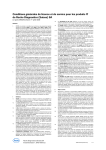
Figure 1 illustrates the initial conceptual model that appears in the technical annex of the project to
serve the logical basis for underpinning the detailed AIM architecture.
Home Power Network
Powered On
Appliances
Standby
Appliances
Energy
Monitoring & control
Local Grid
Management
Unit
Home Network
Bridge
AIM core logic
Virtualisation
Semantics
Local energy network operator
(Local Grid)
Decision
Making
Energy Management
Logic
Home Communications
Network
Services
Optimal Energy
Production
Planning
User
Services
Operator
Services
Communication Network/Service
Operator
Figure 1: Conceptual model of the AIM architecture
Main innovation of the proposed approach in managing the energy of household appliances,
constitutes the bridging of functionality of home communication and power distribution networks
with the aim to control the latter by the former through communication services.
The AIM gateway is a communication component that has the ability to host user services, while
serving communication with user terminals over the indoor and outdoor networks and implementing
control of the power line network by employing special, power line communication interfaces. The
AIM gateway has a key enabling role in coupling the two home network types.
Apart from providing bridging logic, the AIM gateway implements the basic substrate for:
The deployment of user services,
The implementation of interoperability between network components, such as sensors,
household appliances, specialised network components, etc, and for,
The accommodation of service creation and execution environments.
Thanks to the adoption of the AIM gateway, the AIM architecture may host service requirements
coming from diversified user groups and implement flexible interconnection schemes with the
components needed for appliances energy control.
Concerning the last two issues, given the current time and budget limitations, in building up its
architecture the AIM project will address mainly three user groups and three appliance categories.
Nevertheless, to retain applicability of the resultant technology on other household appliance types,
© AIM consortium 2008/2009/2010
Page 13 of (125)
AIM
Deliverable D2.2
such as water heaters, solar panels, etc, the project will deploy generic solutions, wherever selection
between diverged technologies should be made.
1.2
Identification of functional components
Figure 2 shows a first instance of the AIM architecture as it has been conceived by the time of project
preparation. In this initial architectural diagram there are two main components with significant role
in the organisation of communication between the appliances and the services of the network. The
EMD and the AIM gateway are not only key components in the implementation of interoperability
between the appliances and the user services, but also offer the basic communication substrate for the
realisation of higher-level logic that pertains to user operations management and the control of
appliances’ functionality.
Figure 2: Instance of the AIM architecture as outlined in the technical annex
To be able to identify such higher-level logic and its relations with the lower-layer network
components we draw up a second instance of the AIM architecture, which is depicted in Figure 3.
This instance aims at illustrating organisation of the internal architecture components according to
their intra- and inter-relations within or outside the frame of the two main components.
For reasons of maintaining an overview of the system requirements, this second architecture instance
has organised components in correspondence to the main requirements diagram set out in figure 1 of
D2.1. This way it can be easily deduced which components are affected, when, for example,
requirements for the network are in question.
The main functional entities identified in the figure above are:
The AIM core logic, that will be hosted partially in the wide area network and partially in the
AIM gateway;
The EMD;
The appliances and the network part that concerns communication of the appliances with the
EMD;
The user applications and the network part that concerns communication of the users with the
AIM gateway.
The ‘components’ are the functional entities. Among these components some are totally internal to
the functional entity and some appear as traversing two or more functional entities, behaving as
‘links’ between the functions provided by each functional entity. The AIM gateway and EMD
Page 14 of (125)
© AIM consortium 2008/2009/2010
AIM
Deliverable D2.2
functional entities provide the core logic of the architecture. In particular, the upper layer functions of
the communication substrate are offered by the AIM gateway and the IP connectivity components,
whereby it ensures communication with the users, the EMD and the appliances.
On top of the latter two components there are the identity management and secured & privileged
access components. Both components belong to the same functional level because they implement
essential service access functions, such as user recognition, privileges identification for service access
and secured communication with the components of the outdoor network.
On top of the identity management and secured & privileged access components, there is a device
virtualisation environment, whose purpose of existence is to enable residential users to define in an
abstract way energy management functions, using proper semantics that will be built up in the context
of the project.
The output of the device virtualisation environment is fed to the service personalisation & creation
component, which undertakes ‘incarnation’ of the energy management function in the form of
singular service. Finally, the services born in the latter component are exploited as individual service
components in the context of energy control, monitoring or metering applications.
Figure 3: Instance of the AIM architecture
The EMD functional entity is linked with AIM gateway functional entity via the IP connectivity
component, meaning that communication between the AIM gateway and the EMD is implemented
over the IP protocol. The EMD is the functional entity in charge for implementing energy
management functions towards the household appliances. As such, it employs two types of
communication interfaces: a low-level power line interface that allows physical communication with
some appliance types and also facilitates real time measurement of energy consumption for the
appliances that are connected to the same power line of the mains; and a high-level type that is
employed solely for exchanging control and status information with household appliances
implementing custom-made communication protocols. The latter interface may not necessarily be of
power line type but is subject to the choice of the appliance manufacturer.
© AIM consortium 2008/2009/2010
Page 15 of (125)
AIM
Deliverable D2.2
In addition to the two core functional entities, the architecture provides a group of household
appliances encompassing functions, which must be managed in terms of energy consumption, and a
number of user applications grouped in three use-cases.
The two peripheral entities and the core functional entities are altogether connected via the IP
protocol. Moreover, further enhancement of platform-automated operations beyond the usual user
configurable scenarios is achieved through the inclusion in the home network of a sensor network that
allows detection of humans’ presence and movements at home. With this addition, the platform
becomes capable of accommodating logic for more intelligent energy saving scenarios, such as
automated switch off of the communication equipment when there is no user at home.
All four functional entities outlined in this section are specified in detail, in terms of internal logic, in
chapter 4. In the following two chapters we identify the operation modes that the AIM architecture
must support in order to retain compatibility with user requirements and give an account of its
services and applications.
1.3
Operation modes
To enable services and applications implementation, the AIM architecture has envisaged two basic
modes/profiles of operation: monitoring and active control. Formation of services will be
implemented as combination or utilisation of either of these modes.
In the monitoring mode the home network only receives energy consumption figures of the
connected appliances. These figures may be made available to users wishing to monitor in real time
the energy consumption of their homes or may be aggregated by applications exploited by institutions
having interest in profiling energy consumption of neighbourhoods or larger geographical areas for
better energy generation planning or statistical use.
In the energy monitoring mode, power consumption values can be obtained in two ways distinguished
by the ability of the appliance to communicate to the network the mode is in.
The first way relates to appliances of which power state cannot be sent to the AIM gateway by the
appliance itself as either there is no possibility for external communication in form of primitives
exchange or the protocols used for such purpose are confidential and therefore not beneficial for the
project. In this case the EMD is used for measuring in real time the energy that these appliance types
consume. As is defined in D2.3, appliances of such type are profiled experimentally, by measuring the
consumed energy in each supported mode. Following this method, all experimentally measured
energy consumption values are set in the database of the AIM gateway in order to be compared with
the values that the EMD measures in real time.
The second way relates to appliances that “understand” the mode they are currently operating and also
to the possibility of communicating it to the network in the form of known messages. Measurement of
the energy consumption of these appliance types does not involve the EMD. The appliances make
known their status to the AIM gateway, which retrieves the actual consumption value from the profile
record of the database.
In the active control mode, the network has the ability to enforce changes in the status of the active
or standby devices. Such a feature is useful for the implementation of energy conservation services,
where a certain threshold of energy consumption is set by the user and the AIM gateway attempts to
achieve it by masking particular appliance functions of which energy consumption exceeds the agreed
threshold.
Switching of appliance internal modes in the active control mode, is achieved through the exchange of
control primitives between the EMD and the household appliances. The notion of which appliance
function must be masked or replaced by any other lower consuming one is taken by the AIM gateway
after parsing the profiles of the appliances found in the home environment.
Page 16 of (125)
© AIM consortium 2008/2009/2010
AIM
Deliverable D2.2
1.3.1
Services and applications
The AIM architecture is going to support a number of services and applications.
With the term service we identify the network logic concerted under the control of AIM gateway in
order to yield particular types of network functions that can be made available to the users of the AIM
system in the context of user applications. For example, the monitoring of appliances’ energy
consumption is a form of service that network may offer to users. Another form of service is the
ability of the gateway to control internal appliance functions.
All services of the AIM system are accommodated on the AIM core logic that may be hosted by the
AIM gateway or by a "cloud-based" service platform, so that the home users may manage them by
removing, modifying or designating no one’s using the virtualisation environment.
With the term application we identify the piece of software that the user exploits in order to access
the services of the AIM core logic. Each application may use one or combinations of available
services in order to yield desired functionality.
For better technical overview and user requirements visibility, the project has categorised user
applications in three use-cases, each one addressing the requirements of particular user groups.
According to those user requirements, the project will design and develop a number of applications
(in the context of the WP4), at least one per each use-case, to be used for the evaluation of the overall
system.
1.4
Security design of the AIM architecture
1.4.1
Design of authentication, identity and policy management
The residential gateway (RG) with the device virtualisation environment (DVE) is the main access
point for the end-user of the AIM system. Therefore the realisation of authentication, identity and
policy management rests on the RG.
Access to the system is available:
• Locally by accessing directly the DVE via a web based Graphical User Interface (GUI)
• Remotely by mobile phone service managed by telecommunication operator
Local access: The home access to the DVE services is possible through a Web GUI. Access to the
GUI is protected by a username and password login. Since the local GUI is already located in a secure
environment with limited access (only family and guests) this security mechanism is sufficient for
local authentication. For access over a WiFi network, the communication channel must be protected
by at least WEP or WPA security.
Remote access: The telecommunication operator provides a mobile GUI in order to let the user access
some DVE services when he/she is outdoor. Outdoor user identification for the AIM system is
provided by the telecommunication operator. He is able to recognize the users through their mobile
SIM number and filter the request in the telecom platform before reaching the households.
The DVE - telecommunication operator communication is provided by a Web Service (WS) exposed
by the DVE through the RG. The WS communication is protected by three security levels:
1. The GW that hosts the DVE software has a firewall that accept connections only from the
telecommunication operator IP
2. The entire communication is based on the secure protocol HTTPS
3. The connection to the web server that hosts the DVE WS require a user and password
authentication
© AIM consortium 2008/2009/2010
Page 17 of (125)
AIM
Deliverable D2.2
The management of user identities in the AIM system in the household is handled on the RG by the
DVE. Each user of the DVE is assigned to a role, which then determines his or her access to the
system. Three roles for the local GUI are already known today:
• administrator
• advanced user access
• basic user access
Furthermore a user for external access can be seen.
For these roles a policy-based access to devices in the DVE is established. Each role is related to a
different view of the local GUI. When a user accesses the GUI he is automatically directed to the GUI
view associated with his role.
A basic user, generally associated with a common user with little technological experience, has
access only to the simplest functions of the DVE (i.e. program a new task on a device). Major
changes requested from the basic user require an administrator intervention.
An advanced user has more functions available than the basic user. He has full control of the
devices and environmental settings related to him.
They are both not able to access and modify system settings that are managed only by administrator.
Typically, users and their policy are generated during installation phase of the AIM system.
Management of these policies itself has to be restricted to users with administrator role, of course.
A detailed description of the authentication, identity, security and policy management in the DVE will
be provided in the Deliverable 4.3.1.
Another part of identity management is the management of the DVE identity when communicating
with external networks for privacy reasons. Controlling the information accessible from outside
networks is already possible through the access limitations for different roles. Privacy can also be
ensured by removing the identifying information from the data. This requires an intermediary node,
which shields information like IP addresses from the host in the outside network. For the telco
operator's services privacy is only limited to which information can be accessed, as the telco knows
the IP addresses assigned to the household and must connect the mobile GUI running on a smartphone
to the matching AIM system. For the utility operator a communication scenario with pseudonymity
can be constructed. The goal would be to deny the utility knowledge of specific household
information when receiving the schedule of energy consumption for each household. Here the telco
operator would act as a pseudonymiser, masking the DVE ID sent as identifier with a pseudonymous
ID. The utility would then only know that these households with their scheduled consumption exist
and could address them for load saving request by their pseudonym. The telco operator would be able
to undo the pseudonymisation.
1.4.2
Communication through firewall and NAT
Communication between a home network running behind a router with dynamic IP addresses and a
firewall is a standard problem for households using e.g. DSL connections. Therefore several solutions
for establishing communication with a node behind a firewall and NAT exist.
The easiest possibility is to open a pre-defined port in the firewall. The opened port is then re-routed
with NAT forwarding rules to the residential gateway (RG). Security in this scenario has to be
provided by the RG. Since the DVE external interfaces of the RG are based on Web Services, the
opened ports should be HTTP or HTTPS, which is more secure.
Alternatively, a virtual private network (VPN) can be established between the communication node
on the outside and either the router itself or a VPN gateway in the network. In the latter case, VPN
connections have to be re-routed to the VPN gateway. The security features of a VPN enable the
external host's communication to be treated like a node on the local network.
Page 18 of (125)
© AIM consortium 2008/2009/2010
AIM
Deliverable D2.2
Both scenarios are standard internet repertoire and can be employed optionally.
1.4.3
Security architecture and the H interface
Before discussing the comments regarding the H interface, it should be advised that during the
implementation of the AIM architecture described in D2.2 the implementation of a physical interface
H was discontinued. This decision was taken in D3.3.1, submitted in September 2009, in section 2.3.
As described in D3.3.1, section 2.3, a secure communication method to and from the operator network
is possible. An EMD with security capabilities can use a ssl/ssh secure socket layer communication,
which would allow direct access through an opened port of the router's firewall. This technology is a
proven secure protocol with millions of applications today.
For EMDs without security capabilities, a logical communication interface H can be created by
connecting to the Residential Gateway (RG) and using the RG as a proxy for the EMD
communication. The security implementation for accessing the RG is then used for the access to the
EMD.
Both approaches include the requirement of user empowerment. In both cases the user decides, to
whom he gives the credentials (keys, certificates, passwords) necessary to access the EMD – either
directly or via the RG. A detailed management of rules for access control can be implemented on each
device. This allows an administrator to define access rights different users. When using the RG as
single point of access, the rights management can be performed by the device virtualisation
environment (DVE). A single EMD with direct external SSL access has to be either synchronised
with the RG or use separate access control mechanisms.
The concept of access control is a well-known instrument in ICT. Since its bearing on energy savings
is limited, it is not considered a primary concern for the AIM project. The approach of using the RG
as the single point of contact between outdoor network and home network allows enhancing the AIM
architecture with access control at a later point in time.
© AIM consortium 2008/2009/2010
Page 19 of (125)
AIM
Deliverable D2.2
2
Analysis of state of the art and impact on AIM
architecture
2.1
Introduction: Trends in the area of energy saving technologies
2.1.1
Trends in the area of low power components
For many years the situation in CMOS technology development was twofold. For all portable
equipment such as mobile phone or cordless phone energy saving it was a key issue, not for CO2
reduction, but for convenience: to extend the operating time before recharging. Significant effort was
spent to that aim. Special technologies and libraries have been developed with low power
consumption at the expense of performance. Circuit level means such as dynamic clock reduction and
switched (gated) clock have been implemented. Design tools have been adapted to support these
features (normally tools assume clock signal). Power down, sleep modes and switch-off of temporary
unused blocks further improve energy saving.
For all wired equipment, however, energy saving was not an issue for decades. Performance and timeto-market were the main goals, both features having rather tendency to increase energy consumption.
Hence the potential for power saving for chips in wired applications is high. But in practice power
savings will need long time and will be costly. Why?
1. Low power CMOS technologies cannot be used for wired components. They are too much
optimised for power saving at the expense of performance. New processes will have to be developed
with power-performance trade-off optimised for the applications.
2. Mobiles and handhelds have one single low voltage power supply. In wired applications the
environment has sometimes much higher voltage values. Additional protection means are needed such
as SoI (silicon on insulator) or higher breakthrough voltages.
3. Although circuit level power saving means such as gated clock are known their application to
existing circuits need complete rework of existing circuits. In some cases building blocks would have
to be redesigned from scratch. This includes the costly regression tests and bears the risk of
introducing new errors.
4. In the past for the sake of reducing development time building blocks contained unused parts, as
their removal would have consumed more time.
5. A technical fact is that future CMOS technology shrinks will have increased leakage current.
CMOS technology normally has no bias current and consumes energy only at low-high/high-low
transitions, hence proportional to the clock. Halting the clock or reducing it to very low values drove
energy consumption to almost zero. This advantage will be lost for ultimate nano-scale CMOS
technologies. Instead a trade-off between power dissipation, area (cost) and performance will have to
be carefully obtained for each application.
Another aspect is that all components of IT appliances are still under high cost pressure, and time-tomarket is still a major goal. Who is willing to wait one more year for a low power home gateway,
while his colleague/ friend/ neighbour already benefits from the new functionality? And will he accept
the higher price? Hence the advent of low energy chips will depend to a large extent on the consumer
behaviour.
2.1.2
Trends in area of microelectronics
Today’s trends in consumer electronics devices are leaning towards the integration of multiple
functions in a system-on-chip design. Battery-life concerns require management of active and standby
power as well. The designs today address power issues from the very beginning.
Designers are now taking an architectural view of power. Instead of relying solely on physical
optimization techniques, they are focusing on power closure early in the design cycle, starting with
the system level, followed by RTL, gate, and layout. The basic idea is that every specific stage of the
design flow can help saving energy.
Page 20 of (125)
© AIM consortium 2008/2009/2010
AIM
Deliverable D2.2
Every consumer-electronics products today is designed in order to do accommodate more functions
with reduced need for energy. Squeezing more and higher performance logic into smaller areas
requires power management, including attention to packaging, cooling, heat absorption, and
dissipation.
2.1.3
Trends in area of software
In addition to choosing low-power components and/or reducing leakage current in their designs,
producer has started writing more efficient software control. Inefficient software design and
implementation can void power saving gain at component and system design stage.
As the power consumption of the involved component depends also by the software that control the
frequency, operation mode, and pin states. The most efficient power-management scheme controls
each component's power supply in a device, through software, shutting off power to components not
needed, or placing components in sleep mode.
A lot of focus appears to be on power-aware physical implementation vendors, including clock gating,
voltage domains, power-aware-clock placement, gate sizing, and dual-Vth optimization.
To deal with power-management issues on power analysis and optimization at all levels in the design
flow, from architecture to sign-off. New complementary tools have been developed as like as
optimization platform for concurrently reducing the active and leakage power while maintaining
timing and signal integrity.
2.2
Proceedings of standardisation bodies/industrial forums
This chapter summarizes information on governmental, private and industrial bodies working on
energy saving applications and environmental impact mitigation strategies. Details of these bodies
have been extracted from the Methodology deliverable D1 of the ITU Focus Group on climate change
(http://www.itu.int/ITU-T/focusgroups/climate/).
Table 1 provides an overview of standardization work in progress. This ranges from the development
of standards for the collection of data that are used in climate models through to the labelling of
products sold to the general public. Further details of the work of the various bodies are given in the
subsequent sections.
© AIM consortium 2008/2009/2010
Page 21 of (125)
AIM
Deliverable D2.2
Organization
Area
Policies
International
Others
UNEP
and
World
Bank,
International
Energy Agency
European Commission, OECD
Indicators and statistics WMO
OECD
Data collection
IEEE SCC 40
ISO TC 211
Environmental management
ISO TC 207
-
Corporate reporting
ISO JTC1/SC7
Greenpeace,
Initiative
GHG
Protocol
Energy efficiency
equipment
of
IEC, ISO, ITU-T
ATIS, CENELEC, Energy Star,
ETSI
Energy efficiency
networks
of
ITU-T
Ethernet
Alliance,
Energy
Efficiency
Inter-Operator
Collaboration
Group,
FTTH
Council, IEEE P802.3az, TIA
Energy efficiency
data centres
of
-
Efficient Servers, Green Grid,
TIA
Electronic waste
-
Basel Convention (MPPI &
PACE), European Commission,
TTA
Equipment labelling
-
Collaborative Labelling
and
Appliance
Standards
Programme,
CEN/CENELEC,
Energy Star, TCO, Electronic
Product
Environmental
Assessment Tool (EPEAT)
Table 1:
Overview of standardization bodies work
As an extensive analysis of these standards will be made in the WP6 deliverables below we present
two bodies that are mostly relevant to the work of AIM: the ITU Focus Group on climate change and
the EE group of the ETSI, on the built up of environment-aware communication technologies.
2.2.1
The ITU FG on climate change
The Focus Group has the scope of identifying, from the standardization viewpoint, within the
competences of ITU-T, the impact of ICT on Climate Change, in particular the reduction of ICT’s
own emissions over their entire lifecycle (direct impact), the mitigation that follows through the
adoption of ICTs in other relevant sectors (indirect impact), and facilitating the monitoring of relevant
climate parameters.
With respect to this scope, the FG analyzes and identifies gaps in the areas of definitions, general
principles, methodology and appropriate tools to characterize the impact of ICTs on Climate Change
and support the development of appropriate international standards.
The FG is currently working on three deliverables, D1 on terms and definitions, D2 on gap analysis of
existing standards and D3 on methodologies for the calculation of the impact of ICT on energy saving
and CO2 emissions.
The AIM project has already performed a project presentation at the group’s plenary meeting held on
1st September 2008 and three contributions to deliverable D2. Furthermore, the project is co-editor of
Page 22 of (125)
© AIM consortium 2008/2009/2010
AIM
Deliverable D2.2
deliverable D2 and plans to continue contributions to D3, after D2 is finalised at the end of the year
2008.
2.2.2
ETSI EE
The Technical Committee EE is responsible for defining the environmental and infrastructure aspects
for all telecommunication equipment in different types of installations.
The Environmental activity covers:
Environmental conditions on the telecommunication equipment (mechanical, biological and
climatic conditions);
Active substances (mechanical and chemical);
Equipment acoustic noise emission;
Environmental tests for all telecommunication equipment and facilities, including customer
premises;
Observation of European environmental legislation, in terms of ecological aspects, and
assessing its impact on Telecommunication infrastructure and equipment.
The infrastructure activity covers:
Definition of the power supply interfaces of all telecommunication equipment, installed in
telecommunications centres, access network and in customer premises. This includes aspects
of power supply system, earthing and bonding methods of telecommunication equipment and
supervision and monitoring of power and cooling systems;
Definition of equipment practice for telecommunication equipment installed in
telecommunication centres and outdoor enclosures and of the thermal management standards
for the co-location of equipment delivered by different suppliers in the same facility or ETSI
rack.
Environmental activity in terms of ecological aspects covers the combination of climatic, physical,
chemical, and biotic conditions that may affect the growth and welfare of organisms and nature
conservation. In particular:
The reduction of energy consumption in telecommunications equipment and related
infrastructure;
The alternative energy sources for powering telecom/datacom equipment.
The main standards produced and maintained by EE are:
EN 300 019 series: Environmental conditions and Environmental tests for
telecommunications equipment;
EN 300 132 series; Power supply interface at the input to telecommunications equipment;
EN 300 119 series: European telecommunication standard for equipment practice;
EN 300 253: Earthing and bonding configuration inside telecommunications centres.
EE liaises with the major worldwide standard organizations (e.g. ATIS, IEC, ITU-T CENELEC) on
the fields covered by EE. The EE Technical Committee comprises representatives from the
Telecommunication network operators and equipment suppliers of Europe, China, Japan and the US.
Furthermore, in the frame of the EE/EE2 group (powering and control/monitoring interface), ETSI
has recently publicised the new standard ES 202 336-1 on the control/monitoring interface for
network technical environment in the telecom/datacom premises. This interoperable standard is open
and using TCP/IP http XML and so is in line with NGN TISPAN work and the IETF specification for
alarm and performance supervision of internet network.
As the project build on the latest NGN technology, in this specification and in the sections related to
interfaces, the consortium is evaluating this standard with the intention to adopt it in the
implementation of the service management interface.
© AIM consortium 2008/2009/2010
Page 23 of (125)
AIM
2.3
Deliverable D2.2
Communication technologies
2.3.1
In-house communication technologies
There are many field bus communication technologies on the market for different uses, like car
technology, industrial automation and home and building automation.
For the in-house communication in the AIM project the short distance communication based on wires
or wireless technology is the most relevant. Wired networks like IEEE 802.11 and Power Lines are
common. In some cases special communication networks based on proprietary lines could be found.
For technical equipments of homes and buildings, like heating, climate, lighting, household
appliances and alarm equipment, different companies developed their own field busses. Main
standards in building automation are LON, LCN, BACnet, KNX, EIB, EHS and BatiBUS. In the
following, a short abstract of these technologies is given:
LonWorks (LON) is a field bus system owned by Echelon. It is used for industrial-, buildingand home applications. LON offers features like decentralized networks including routing
facilities. The used protocol is called LonTALK and is standardized in EIA 709.1 and
ENV13154-2. The following transmission media are possible: Twisted Pair, Power Line,
Radio, Infrared, and fibre optic.
LCN stands for Local Control Network and is designed to fulfil all demands on modern
building control and automation requirements. It represents an automation system which can
be easily implemented in any kind of building, like private homes, schools, hotels, hospitals,
office buildings of any size,etc...
BACnet (Building Automation and Control Networks) was developed by the American
Society of Heating, Refrigerating and Air-Conditioning Engineers (ASHRAE). BACnet is an
American national standard, a European standard and an ISO global standard. BACnet
defines multiple physical architectures to handle high and low speed networks, as well as
point-to-point connections. This emulates the structure of most automation systems.
The Konnex (KNX) Technology is an open standard for all applications in home and Building
control. It was established by the Konnex organisation in a convergence process with the
former European Installation Bus (EIB), BatiBUS and European Home Systems (EHS). KNX
is mainly downward compatible with these busses. In the KNX standard for the physical layer
the following transmission media are defined:
o Twisted Pair,
o Power Line 110 (PL110, center frequency110 kHz, 1.200 Bit/s) (EIB compatible)
o Power Line 132 (PL132, center-frequency 132 kHz, 2.400 Bit/s) (KNX, EHS
compatibility in KNX „A-mode“))
o Radio frequency (RF), 868 MHz, 38,4 Kbit/s
KNX brings a lot of comfort and flexibility to homes and buildings. The KNX is called to be
"the world's only open STANDARD for Home & Building control". The first KNX Standard
1.0 was defined in 1999. It is specified in the European standard EN 50090 and the
international standard ISO/IEC 14543-3.
The European Installation Bus (EIB) is the successor of Installation Bus (Instabus). It is a
decentralized open system to manage and control electrical devices within a facility. EIB
allows all electrical components to be interconnected through a proprietary electrical bus.
Every component is able to send commands to other components, no matter where they are
located. All devices within the network are connected with an electrical bus made of twisted
pair cable. The EIB bus topology is assimilated to home and building constructions. It is
based on a peer-to-peer network in combination with couplers. The EIB is one the leading
field busses in Europe for home and building applications. EIB is an open standard and was
developed to increase power savings, security, comfort and flexibility.
European Home Systems (EHS) defines architecture for device communication, discovery
and control. Through the EHS network, a white goods appliance can advertise its state and
Page 24 of (125)
© AIM consortium 2008/2009/2010
AIM
Deliverable D2.2
services and can receive remote commands. The European Committee of Manufacturers of
Domestic Equipment (CECED) defines unified objects and actions for white goods
appliances. As transmission media are defined: twisted pair, powerline, coaxial cable, radio
frequency, Infrared
BatiBUS presents one of the first field busses for home and building automation. It was
developed to control sensors, actors and appliances and make communication between them
possible. Applications for this bus are climate and ventilation, illumination and lighting and
security and alarm technology. Twisted pair cables will be used as transmission medium.
BatiBUS is standardized by CENELEC and under ISO/IEC as JTC1/SC25.
All these standards should be interoperable with the AIM EMDs and equipment. It should be able
to fit and be a part of the AIM architecture.
2.4
Research projects
A number of research projects are active in the field of energy management technologies.
Project Acronym
Field of work
DINAR
Management of energy sources and supply
DEHEMS, BEAWARE, BEYWATCH, AmI- Monitoring technologies for CO2 mitigation,
MoSES, DIADEM, INTUBE
energy sparing
E4U, GENESIS
Synergy creation and policy shaping of energy
aware initiatives for Labelling, CoC, etc
Table 2: Relative research projects and area of involvement
AIM is mostly related to those projects working on monitoring issues and in particular with
BEYWATCH and DEHEMS. Both projects deal with technologies of household energy monitoring,
as well as with methodologies for “connecting” households’ energy consumption with CO2 emissions.
With regard to these two projects, AIM offers the enabling technology that allows generic profiling
and energy measurement of the appliances composing the home environment. Moreover, through its
use-cases, AIM offers a generic methodology for appliances energy management and control that can
be adopted by the two projects in the development of their monitoring solutions.
A brief description of these projects can be found in Annex: “Related research projects description”.
2.5
Challenges and identification of progress beyond state-of-the art
The challenges in the state-of-the-art affecting the project are summarised in chapter two of this
deliverable, where the trends in the area of energy saving technologies were identified, specifically in
low power components, microelectronics and software.
Concerning the trends in the low power components, they affect the design of the AIM low power
home gateway. Concerning the trends in the microelectronics, the fact that every consumerelectronics products today is designed in order to do accommodate more functions with reduced need
for energy affects the project work in the sense that AIM architecture will make use of these functions
to manage the energy consumption reduction.
Concerning the trends in the software, the efficient power-management scheme for controlling each
device components' power supply, shutting off power to components not needed, or placing
components in sleep mode were considered in the AIM's Energy Management Device (EMD).
Adopting as the baseline of its work plan the state-of-the-art approach introduced by the ADSL
Forum, the project will extend the concept of using discrete power mode levels for mapping the
© AIM consortium 2008/2009/2010
Page 25 of (125)
AIM
Deliverable D2.2
various communication modes of xDSL modems and DSLAMs, in the operation of white goods
(refrigerators, ovens, washing machines, dryers), audiovisual equipment (TVs, DVDs, Set-top-Boxes)
and home communication devices (wireless routers, DECT phones, residential gateways, modems),
and will introduce new power levels appropriate for mapping the modes of operation of all household
appliances. This way it will be made possible to associate, the power consumption of each household
appliance internal function with one metric, the power mode level, and thus devise the basic
technology for "green" products, featuring partial power up capabilities organised in "user logic"
blocks.
Having devised a number of power modes for use by all home appliances, and a technology for the
virtualisation of their power consumption, the project will work on profiling their energy consumption
by associating the energy consumed by the appliance with the power mode it is in. This will be made
possible by processing the real time power consumption measurement being sent by the appliance
over the home network to a central processing point (i.e. a residential gateway) with its current power
mode. Achieving this goal will allow the project to introduce accurate power metering services to be
hosted in the home network (e.g., on residential gateways as OSGi services) or be offered on standard
terminals through operator networks.
Having defined discrete modes of operation, the project will be able to draw up a new state-of-the-art
activity, that of establishing mechanisms for appliances functionality virtualisation using semantics
technology. With this new technology the user will be able to program alone energy resources
distribution among the appliances at home by configuring energy consumption per appliance type and
internal function.
Concerning the problem of stand-by devices power consumption management, the project will draw
up a new state-of-the-art power management technology that will feature intelligence in tracing and
switching off stand-by devices, autonomously, by invoking special, network controllable, power
switching devices. This technology will be mainly based on the interception of events, being sent over
the home network to a centralised control point at the moment an appliance enters the stand-by mode,
and in more intuitive scenarios, on the processing of the power consumption measurement.
Page 26 of (125)
© AIM consortium 2008/2009/2010
AIM
3
Deliverable D2.2
Specification of use-cases
The functionality that will be offered by the AIM system is intended to be used by four different types
of users, namely utility providers, telecom operators and third party service providers, device
manufacturers, and of course the local users themselves. This chapter provides representative use
cases of the AIM system that were developed from these four distinct directions. Note that we do not
attempt to provide an exhaustive list. The outcome of the discussion of this chapter will motivate the
need for specific functional components in the AIM architecture.
AIM System
**
Control Energy Use
*
*
**
Home User
*
*
Utility
Monitor Energy Use
*
*
*
Personalize &
adapt System
*
Tech-savvy home user
*
*
Environment
*
*
*
*
*
Manage System
*
Expert Home User
*
*
**
Third party service provider
**
Maintain System
*
*
network & service operator
Appliance Manucaturer
Figure 4: Example of responsibility use case
These diagrams represent as ellipses the top-level use cases main functionalities of the system, inside
the boundary of the system (rectangle), with the actors (external to the system) who are involved in
these functionalities.
The distinction between management, maintenance and personalization of the system is explained at
the beginning of this document.
© AIM consortium 2008/2009/2010
Page 27 of (125)
AIM
Deliverable D2.2
The distinction between three possible roles of the user is not set in stone and some users will
obviously straddle all three roles depending on their inclination. What is important is the idea that the
system can be operated in default mode (corresponding to the default "home user" role) without any
tinkering or even requiring reading a user manual.
The "tech-savvy" home user does at least read the user manual and adapts the system to his/her own
preferences. The expert user is able to engage in adaptations that are more technical and may update
the system himself when e.g. new equipment is added.
The most difficult and/or tedious maintenance tasks (lifecycle of software, correction of bugs, etc) are
supposed to be performed by service providers.
For each user type a number of services are feasible concerning energy use management and energy
use monitoring.
AIM System
Local
Mng.
Remote
Mng.
<<extends>>
<<extends>>
Energy Use
Management
Utility
Home
user
Energy Use
Monitoring
<<extends>>
Local
Mon..
<<extends>>
Remote
Mon.
Figure 5: Feasible services for the AIM system
3.1
General sequence charts
Following the description given above, in this section we outline the sequence charts that convey the
operation of the basic functions of the architecture.
In sections below the term ‘remote’ is valid for both indoor and outdoor usage of AIM services. Its
adoption has been deemed necessary for the differentiation between the normal user-appliance manual
interaction and the envisaged AIM-related user-appliance, through the network.
In the figures depicted below the dashed lines symbolise return/response messages and the full lines
originating messages.
3.1.1
Remote monitoring
The remote monitoring is a core AIM use case that involves all AIM entities. In the monitoring use
case the user submits a request for monitoring the energy consumption of the home environment, a
specific appliance or a set of appliances and receives back a real time energy consumption figure.
Page 28 of (125)
© AIM consortium 2008/2009/2010
AIM
Deliverable D2.2
As it is depicted in the figure below, the gateway has the role of request coordinator towards the
appliances and that of the energy value aggregator and estimator, whereas the EMD undertakes
routing of the requested message toward the target appliance(s) and the reception of the corresponding
responds.
Figure 6: Remote monitoring1
3.1.2
Remote control
In the control use case the user or the AIM logic itself submits to the EMD a control request for for a
specific appliance or a set of appliances and receives back an appropriate acknowledgment.
As it is depicted in the figure below, the gateway has the role of request coordinator towards the
appliances and that of the energy value aggregator and estimator, whereas the EMD undertakes
routing of the requested message toward the target appliance(s) and the reception of the corresponding
responds.
1
Dashed lines: return/response messages, Full lines: originating messages
© AIM consortium 2008/2009/2010
Page 29 of (125)
AIM
Deliverable D2.2
Figure 7: Remote control
3.2
Operator
The following section presents in detail several use cases that are important for the telecom operators.
They are mainly focusing on the energy management related services. Detailed UML diagrams are
also provided.
3.2.1
UC Operator 1: service provisioning
Description
This scenario describes the service provisioning. It involves two entities: the third party that has
developed a service and the operator which checks the service bundles and can guarantee uploaded
software in the AIM gateway.
Figure 8: Service provisioning
Page 30 of (125)
© AIM consortium 2008/2009/2010
AIM
3.2.2
Deliverable D2.2
UC Operator 2: service subscription
Once services are available on the operator platform, users can subscribe to a service. He selects the
service on the platform, installs and activates the service.
Figure 9: Service subscription
3.2.3
UC Operator 3: service configuration
The user can modify some parameters of his services. The Service platform offers a graphical
interface to modify parameters. If one or more parameters are modified, the Telco bundles of the AIM
gateway wake up service bundles. A telecommunication API allows service bundles to upload new
values of parameters.
© AIM consortium 2008/2009/2010
Page 31 of (125)
AIM
Deliverable D2.2
Figure 10: Service configuration
3.2.4
UC Operator 4: detailed invoice
Mister Smith considers his electricity invoice too expensive. He would like to understand why his
home is so energy consuming and how he can reduce himself his invoice.
He has already subscribed to Orange services and has access to the Orange portal named
"MyHouseOrange.com". The portal allows him to subscribe to an energy consumption detailed
service.
After the subscription process, he receives a pack with one or more EMD. If it is his first subscription
to Orange home services, he receives also an AIM gateway to connect to his broadband access. If he
has already an AIM gateway he doesn't need a second one.
After self and simple installation, he can consult on the "MyHouseOrange.com" portal a detailed
description of use (kW and Euro) of each electric device, or type of devices, or by usage.
Page 32 of (125)
© AIM consortium 2008/2009/2010
AIM
Deliverable D2.2
3.2.5
UC Operator 5: easy configuration
Mrs Jones has already subscribed to the Energy pack service. She would like to configure her service.
The service supports three modal interactions:
- She can download the Orange widget to configure the service, to send commands or
receive status from devices;
- She owns an innovative physical device to configure the EMD;
- She has a dedicated application or an Instant Messaging client on her mobile;
She doesn't want to login each time she wants to consult or configure her service.
3.2.6
UC Operator 6: outdoor location
Mr and Mrs Niel have no kids and have a holiday house. At the end of the weekend, when they leave
it, the Orange Mobile network detects that they left the local GSM cell and go back to their main
home. Then, the service switches off the heating system and electronic devices if necessary.
When the Orange mobile network detects they are going to their holiday home, the service starts
heating system in order they find a comfortable temperature.
3.2.7
UC Operator 7: abnormal situation
Mr Niel has configured his services (with UC2) interface to receive an alarm when abnormal energy
situation occurs. He receives a SMS with abnormal situation description.
3.3
Utilities
© AIM consortium 2008/2009/2010
Page 33 of (125)
AIM
Deliverable D2.2
3.3.1
UC 1 Utilities: flexible tariffs
The utility wants to introduce an incentive based business model which means that the customer can
directly participate in savings and benefits that the utility can generate through a flexible cost model.
To realize such a business model a communication path between the utility and the customers, which
provides the required information (tariff/pricing information), has to be established and the customer
needs to have a device which is at least capable of displaying the actual tariff-information. This
functionality should be provided by the AIM-gateway.
One possible way for introducing flexible tariffs is that the utility sends a pricing profile for the next
day which includes the tariffs for every hour. This would be just a finer differentiation of “timeslices”. In peak times the energy would be more expensive than in off-peak times. Now the customer
knows when the more energy intensive services should be used.
Another way for flexible tariffs would be the possibility for customers to buy a certain amount of
kilowatt-hours for consumption. This would require more communication between the utility and the
customer, since a purchase order must be carried out and the crosscheck whether the purchased
amount of energy is already consumed needs more communication between customer and utility.
Nevertheless, the AIM Gateway can be used as central device to organize the communication and
information exchange between utility and customer.
Utility
Gateway
EMD
Refrigerator
Authentication
Hourly Tariffs
download
Information request of EMD for planning
of energy usage
Download pricing information
Internal information processing
and resource planning
Information about scheduled
energy usage
Upload planned consumption
Figure 11: Sequence diagram for flexible tariffs
3.3.2
UC 2 Utilities: remote load control
In times of frequently changing prices and changing availability of additional power generation
capacities the requirements for remote load control becomes a challenging aspect in power grid
operation.
When a utility knows that in its network unused load which can be controlled remotely is available, it
could plan with that buffer to be able to buy cheaper energy.
Mr. Schmitt owns a refrigerator which is capable of producing cold air and stores it in a separate part
of the fridge to be released when required. The required amount of energy for that operation is known
to the utility. In times where alternative energy generation is able to provide very much energy (e.g.
Page 34 of (125)
© AIM consortium 2008/2009/2010
AIM
Deliverable D2.2
strong winds for the windmills) energy becomes much cheaper and cleaner which is an advantage for
all parties.
This kind of remote control would allow the use of carbon dioxide free energy when it is available
and would help to integrate this kind of energy generation better into the whole system of energy
generation and usage.
Utility
Gateway
EMD
Refrigerator
Authentication
Upload available load resources
Remote activation of load
Remote activation of refrigerator
Operation according to given parameters
Upload available load resources
Information about availbale load
resource
Figure 12: Sequence diagram for remote load control
3.3.3
UC3 Utilities: remote control energy creation
A special use case for remote control is to control distributed energy generation. This would mean that
the utility can “build” a virtual power plant by controlling the different available distributed energy
generation sources from the customers connected to its distribution network.
3.4
Local users
According to the general use case diagrams presented above, local users can interact with the system
to perform a set of basic set of operations that include the monitoring of energy use, the
personalization of energy use and gateway maintenance (for expert users only).
In the following we specify in more detail these use cases for local users and include also the
interaction of the sensor network with the system.
3.4.1
UC Local users 1: monitoring energy use
© AIM consortium 2008/2009/2010
Page 35 of (125)
AIM
Deliverable D2.2
Local service
interface
user
EMD
...
Activate interface
Home
Gateway
Request data set
Application data
Return data set
Display default page
Application data
Application data
Request detailed view
Request data set
Application data
Application data
Return data set
Display detailed view
Application data
Application data
de.-activate interface
Application data
...
Figure 13: Local monitoring of energy use – sequence chart
Home users can access to the energy use monitoring service of the AIM system through a local
interface to the service using a terminal (PC, PDA, etc.) that is connected to the home gateway via the
home networks. Data provided by the service is obtained in general aggregating and elaborating raw
data provided by the EMD(s). The specific data provided and the way in which it is presented to the
user depends on the monitoring energy use application that is installed in the home gateway.
3.4.2
UC Local users 2: personalize energy use
Energy management
Service (AIM application
that include control logic)
Personalize
Energy Use
<<includes>>
<<includes>>
Home
user
Set
param.
Sensor
Network
<<includes>>
<<includes>>
Provide
task
Provide
schedule
Set
operational
mode
Figure 14: Diagram for personalized energy use
The personalization use case is enabled by an energy management application that is installed into the
home gateway and can be accessed locally through a service interface or remotly trough the service
Page 36 of (125)
© AIM consortium 2008/2009/2010
AIM
Deliverable D2.2
platform provided by the network operator. This application includes the energy management logic
and allows the user to define the way in which home appliances operations are orchestrated by the
AIM system. The user is required to provide some inputs to the application and, depending on the
level of expertise, it is also allowed to configure and personalize the control system. The sensor
network can simplify the task of the home user providing automatically some inputs to the system.
Figure 14 shows a more detailed use case diagram of the energy use management that includes a set
of use cases that can be available to the users and the sensor network.
The use case set parameters considers all operations that allow a user to modify the parameters that
are used by the system control logic, such as for example the parameters of the utility function that
define the cost/comfort trade-off, the desired temperature levels of the various operation modes, etc.
The use case provide task considers the operations for requesting the execution of a specific task to
home appliances, like, for example, cook the meal by 7PM, wash clothes during night, etc.
The use case provide schedule allows to set the schedule of activities to be performed by the system
and to inform the system about the presence of users at home or in some specific rooms of the home.
The use case set operational mode allows the user to set some predefined operational modes of the
system, like, for example, activate the night mode of the heating systems or the vacation mode of the
global system, etc.
The use cases provide schedule and set operational mode can also be accessed by the sensor network
that can for example schedule some activities (like e.g. run the washing machine) or set an operation
mode (like e.g. turn off a set of devices off) when it detects that the users are no longer at home and
will likely come back when the scheduled activities are over. The sensor network makes use of real
time data sensed by sensor devices and historical data stored into user profiles. Figure 15 shows the
detailed use case diagram of the energy use management.
<<includes>>
Set
param.
<<includes>>
<<includes>>
Provide
task
<<includes>>
<<includes>>
Provide
schedule
<<includes>>
Set utilify function
(cost/confort tradeoff)
Set application
specific parameters
Set operation
program for a device
Set program specific
parameters
Provide normal
activity schedule
Define schedule
exeptions
Set
operational
mode
Figure 15: Detailed use case diagram of the energy use management
© AIM consortium 2008/2009/2010
Page 37 of (125)
AIM
Deliverable D2.2
Sensor network
Identify user
Detect
presence
Home
user
Measure
physical
parameters
Environment
Figure 16: Use case diagram of the sensor network
Figure 16 shows the use case diagram of the sensor network that interact with home users to identify
them and detecting their presence and with the environment to measure some physical parameters,
like e.g. the temperature, the light level, etc.
A sequence chart of the energy use personalization accessed locally by the home user is presented in
Figure 17.
user
Local service
interface
EMD
...
Activate
interface control mode
Home
Gateway
command
Display default page
response
Set energy management
parameter/mode
Set energy management
service parameter/mode
command
response
Display confirmation page
Ack
command
response
command
de.-activate interface
response
...
Figure 17: Local management of energy use personalization - sequence chart
Page 38 of (125)
© AIM consortium 2008/2009/2010
AIM
3.4.3
Deliverable D2.2
Example usage scenarios
Example N°1 – Usage scenario during the workweek
The user is a typical worker that lives in household only in the early hours of the day and come back
in the house in late evening for dinner and the night.
The general objective of the user is to minimize incurred costs and to this purpose he sets the system
with the following general system function: Minimize energy consumption during a period of time
(i.e. 6 hours, 24 hours, week, month)
Objective: minimization of energy consumption during the specified interval of time.
We are in winter, the day of the user start at 7:00AM when he wakes up.
He desires a pleasant temperature in the rooms that he visits in the morning for preparing breakfast
and dressing himself before going out for the work. He sets a temperature of 22 °C in the bedroom,
bathroom and in the kitchen. He doesn’t want to warm up the living room because he doesn’t use this
room in the morning.
While the user is not in the house, it is not necessary warming up any room over a specified threshold
of temperature so, at 8:00AM when the user goes out, the system is free to manage temperature just
considering the cost minimization objective and minimum temperature constraints. Obviously, user
desires that at 7:00PM, when he is back home, the temperature in the house is again around 22 ° C
like in the morning but this time in all the rooms.
The schedule of user’s typical day can be provided to the system through a local interface or it can be
estimated by the sensor network based on the analysis of the time series of user presence at home and
in the rooms of the house.
The user also desires that when he is back at home in the evening the clothes that he putted in the
washing machine in the morning are washed and dried. Accordingly to the general settings of the
system, the goal is to reduce energy cost for washing the clothes. The system can select an available
program to reduce energy consumption considering the type of clothes to be washed. The system is
also capable of managing the schedule of the washing program considering its duration, the
constraints set by the users and the information of energy cost during the day.
Example N°2 – During the workweek with discrete power levels in devices.
Like in previous example, the user is a typical worker that lives in household only in the early hours
of the day and come back in the house in late evening for dinner and the night.
The general objective of the user is to minimize incurred costs and avoiding exceeding a defined
threshold of 2kW/h. The selected general function for the system is: Allocate energy consumption in a
period of time (i.e. 24 h) avoiding exceeding a defined threshold (i.e. 2kW/h).
Objective: energy consumptions are allocated in 24h/day to avoid peaks of energy requests to the
provider.
The energy provider informs that energy is cheaper than usual if the user doesn’t exceed a threshold
of 2kW/h when the maximum power allowed is 3,3 kW/h.
The system operates to have an instantaneous total consumption of energy always below 2kW/h.
The system has also the ability to operate at single connected devices levels and to manage for each
one various power levels diversified for every function that the devices accomplish in every single
moment of time. With this kind of logic the system can power-off single components of the device or
power-on the devices for a longer period of time but with smaller costs.
The user wants to cook a meal in the microwave oven and doesn’t want to exceed a defined threshold
of 2kW/h. The system knows the energy being used by the other appliances and threshold of 2kW/h
and it calculates the residual energy to reach the threshold. Based on the available programs for
cooking the meal and the residual energy, the system chooses the best one.
© AIM consortium 2008/2009/2010
Page 39 of (125)
AIM
Deliverable D2.2
The user also asks the system to manage displays of all the devices based on the presence of the user
detected by the sensor network. Each device is described in the ontology by its components and the
system knows if a display is available on them or not. The system can simply power-on the display
when the user is in the room and power it off when the user leaves the room, or it can perform more
complex control functions considering for its decisions also the time of the day and the estimated
probability that the user will use a specific device. Similarly, the system can manage available discrete
energy consumption levels associated to appliances internal functions or components based on the
needs of the user, his presence in the room and the probability of using a specific device based on user
profile.
The user sets the system to manage automatically the lights in the rooms. He decides to activate the
functions that manage the light bulbs so that to compensate smoothly the growing darkness of natural
light. The light level in the room is detected by the sensor network.
Example N°3 – On vacation
The user leaves the house to go on vacation and his objective is the minimization of incurred costs to
manage the house when he is away.
The objective function that is selected by the user is: Minimize energy cost during a period of time
(i.e. 6 hours, 24 hours, week, month)
Objective: minimization of total energy consumption in a period of time without considering incurred
costs. It is necessary to define if the minimization is operated for a day, week, month or year.
The user can turn off some kind of services available in the house while they’re not going to be used
without him but he needs that some other services are also guaranteed during his holiday.
The system knows the devices that are available to be turned off completely or not.
The user doesn’t need to manage temperature so its control system is turned off.
Devices that usually are in stand-by mode like modem, TV, microwave oven and washing machine
are also turned off.
Refrigerator and freezer stay in power-on state in order to maintain food in good conditions.
A date/time for the return of the user has been provided to the system by the user so it can restore the
normal functioning of the devices before the user is in the house.
Page 40 of (125)
© AIM consortium 2008/2009/2010
AIM
Deliverable D2.2
4
Architecture specification
Figure 18, gives an overview of the AIM reference architecture. The architecture is decomposed into a
number of core functionalities. These components are described in more detail in this section. Several
of these components need to be implemented in devices while others not. Furthermore, we also
distinguish different components based on their importance for realizing AIM services. For example,
the advertisement of EM service by a device is crucial for notifying the home network regarding its
EM capabilities. A relation between the requirements set in D21 and the components of the
architecture depicted in Figure 18 can be found in Annex B.1
4.1
Overall architecture and building blocks description
AIM bridges the outdoor and indoor networks with the view to provide the means for controlling the
functions of the household appliances through a number of different applications addressing three user
categories, the residential users, the network operators and the energy generation utilities.
To realise this concept the AIM project adopts the architecture depicted in Figure 18. In this, the
indoor (home) network is bridged with the outdoor networks through the “AIM system logic”,
whereby users are enabled to manage the functions of household appliances, thus being able of
controlling the energy consumed in their households.
Home Network
Wide area network
Household appliances
(TVs, White goods, comm,
brown goods, etc)
AIM system logic
EMD
Context data acquired
From sensors
end user in
the home
AIM
Gateway
Utility
Operator
Service
Platform
Mobile end
user
Context data
acquired from
external sources
Figure 18: Generic system architecture
In the figure above, the AIM gateway, appearing as a building block of the AIM system logic, may
optionally host part or the whole of the AIM system logic. In the case, where the AIM gateway is used
as a passive component, service logic is hosted on the operator service platform.
The consortium has decided to adopt this flexible service realisation concept for purposes of
preserving scalability and flexibility of the overall architecture. Thus, interested actors (operators,
third parties and home users) have more freedom in the implementation of energy saving applications.
4.1.1
The AIM core logic
The AIM system logic is the main building block of the architecture, providing the interconnectivity
means between the home network and the outdoor networks and the software substrate for the
implementation of energy saving applications.
The building block is comprised of two functional entities, the AIM gateway, providing
communication coupling between internal and external networks and the Energy Management Device
(EMD), providing specialized logic for the implementation of energy management functions.
© AIM consortium 2008/2009/2010
Page 41 of (125)
AIM
4.1.1.1
Deliverable D2.2
The AIM gateway
The AIM gateway has the roles of bridging the functionality of the home network with the user
applications residing in the wide area network (outdoor networks) and providing harmonisation of
communications between the users and the involved network components over the IP protocol.
Concerning realisation of energy saving applications, in cases where the gateway is used as an active
component, it serves as the focal point of services exchanging information with the household
appliances through exposure of an abstract, high-level application programming interface.
For scalability, upgradeability and openness reasons, the gateway should be implemented as an open,
standardised architecture. To fulfil this requirement and to optimise system development the
consortium has selected to adopt the ESTIA gateway which is based on the open services execution
framework of OSGi. Details on the internal architecture of the ESTIA gateway are provided in later
sections.
The ESTIA gateway will host most of the energy management functionality, including:
Appliance capabilities discovery: Appliances shall be traceable concerning the operation
modes they support, e.g. washing programs, cooking programs;
Appliances and user profiling: Appliance profiles as defined in D2.3 shall be stored in a
database within the AIM gateway to be exploited by energy management applications in the
process of deciding which appliances shall be controlled and how. In the same manner users
will be also profiled so that to system is able to administer the energy management strategies
set by each user, judging from their privileges;
Virtualisation environment: This environment will enable the home user to access
household’s energy resources and exploit them in defining energy management processes,
such as maximum energy consumption levels, priorities between appliances, etc.;
Management of the user interface: The gateway shall provide APIs towards the three user
type services, through which user terminals may access the functionality of architecture;
Anonymization of energy consumption statistical data towards the outdoor networks: The
gateway provides a communication substrate that hides the identity of the household and the
user. This substrate is used for anonymizing energy consumption statistical data when it is
processed by external actors, such as utilities involved in energy generation;
Energy monitoring and management: The gateway provides user services with APIs for
communicating with the EMD, the device that mainly performs energy monitoring and
management;
Harmonisation of communication between indoor and outdoor components: The low level
communication substrates of the gateway are designed so that to integrate any IP
communication interface seamlessly to the user services and applications, hence enabling
harmonisation of communication between indoor and outdoor networks.
4.1.1.2
The Energy Management Device (EMD)
The EMD realise an interface role to the energy control logic of the AIM architecture, consisting of
energy monitoring and management.
Energy monitoring consists of monitoring the energy consumed by the each appliance and reporting
the value to the system logic via the AIM gateway.
Energy management consists of maintaining specific energy consumption thresholds set by home
users by applying on household appliances various control models such as state alteration, switching
off and standby management.
Page 42 of (125)
© AIM consortium 2008/2009/2010
AIM
Deliverable D2.2
Figure 19: EMD hardware configurations
The EMD can either be hosted inside the controlled appliance, be integrated inside the residential
gateway, or be an independent device, mediating the communication between RG and controlled
appliance. More details regarding each scenario are provided in section 5 of this document.
4.1.2
The appliances
Appliances are defined as the devices to be controlled by the architecture for energy saving purposes,
through their function modes.
Although only three appliance categories are about to be examined in the context of the project in
terms of energy management, the proposed architecture shall be useful for potentially any household
appliance gathering the following characteristics:
Expose a physical communication interface;
Have discrete operation modes;
Allow operation modes to be controlled through network commands.
4.1.3
User interfaces
Users shall have access to AIM services through applications compatible with any user terminal type.
In particular, home users shall be able to access the services of the AIM gateway through
wireless/wired home terminals, such as PDA and PC based consoles, while outdoor users and third
parties shall be able of accessing home environment through operator services, making use of mobile
phones and PC based consoles.
In some cases, where security and service integrity is guaranteed by third parties operator networks,
outdoor users will be able of accessing their home environment without the need of using an operator
network.
In all cases, the user interface coincides with the user application hosted on the user terminal and
allowing users to access the services of the home network. To preserve solution generality and
viability, AIM leaves the matter of building user applications up to the potential users of the
architecture. Therefore, any application implementation technology and message communication
© AIM consortium 2008/2009/2010
Page 43 of (125)
AIM
Deliverable D2.2
method may be exploited as long as it has no impact on the protocols of the AIM gateway, but
structured access on the services of the platform is only possible through the APIs deployed on the
AIM gateway.
4.2
System functionalities
The architecture is decomposed into a number of core functionalities. These components are
described in more detail in this section. Several of these components need to be implemented in
devices while others don’t. Furthermore, we also distinguish different components, based on their
importance for realizing AIM services. For example, the advertisement of energy management service
by a device is crucial for notifying the home network regarding its energy management capabilities.
4.2.1
4.2.1.1
Energy management
Energy monitoring
Monitoring is an essential feature of the AIM architecture. For users without knowledge of their
power consumption it is hard to save energy and energy costs without losing some living comfort.
Therefore it is important to have some monitoring feature for the AIM devices.
For low level monitoring each household appliance should have an indication for the current state and
power consumption, so that the user can easily recognise its state. This can be provided by the
household appliance or the EMD.
More detailed information could be shown on local communication devices like PCs or mobile
phones as well as web applications. Depending of the functionality of the handhold device, ASCII or
HTML data will be transmitted, either from the AIM gateway or for special functions from the EMD
to the user communication unit. It is important to show to the user the current and history of the power
consumption of the AIM devices and if possible of the whole household. For the user it is not
comfortable to look all the time on his power consumption chart. It will be more convenient to view
the power consumption and the costs of the last day/week/month/year on demand. In parallel a profile
of planed power consumption and offered user adjusted power tariffs from the utility or service
provider should be shown. After comparing the consumption with a former period new decision in
behaviour, controlling and tariff selection can be made.
4.2.1.2
Energy control
The pivot of energy control in AIM is the EMD unit. Apart from its physical interfaces, the AIM
EMD employs a slim version of the IP protocol, which allows it to communicate with high level user
applications, compatible with home protocol technologies, like OSGi, UPnP and HTTP. Particularly,
the use of the HTTP protocol will allow implementation of a Web Server functionality, which will run
locally on the EMDs and will allow an easy EMD configuration.
Realisation of power management applications shall be made possible, through the involvement of the
“device virtualisation environment”. With this environment, a user will be able to access and
orchestrate the power management capabilities of his environment by using semantic representations,
having on one hand the possible administration functions (e.g. monitor, control, etc) and on the other
the addressed household appliances types.
This “device virtualisation environment” will be accessible on the AIM gateway and its functions will
be linked to properties such as service personalisation, user identification and privileged access, all
offered by the ESTIA AIM gateway architecture discussed later-on.
4.2.1.3
The AIM device virtualisation logic
The main building block of the AIM Device Virtualisation logic will be its “Management
procedures configuration environment”. Users will be able to create power management
Page 44 of (125)
© AIM consortium 2008/2009/2010
AIM
Deliverable D2.2
procedures, such as power consumption thresholds, metering functions, etc, through the use of
appropriate administration and appliance function semantic representations. Virtualisation logic is
used because it enables us to buffer-out and mask hardware and software implementation specific
attributes from the rest of the AIM architecture.
Virtualisation is defined as a generalised way of managing the energy consumed by the appliances of
the home environment in the context of the Device Virtualisation Environment (DVE). Appliance
types and operation modes corresponding to certain energy consumption levels are "semantics" that
can be utilised by home users through the GUI of DVE to define their own energy management
strategies. The process by which these semantics are composed with each other so as to build up a
certain energy management strategy is called devices, semantics or even resources virtualisation. In
this context, proper semantics functions are the operation modes that appliances support and which
are associated with specific energy consumption levels.
To implement the management procedure requested by the user, the environment will output its
content to a “knowledge interpreter”, tasked to turn the incoming abstract descriptions into
compatible OMA Device management (DM) logic.
In this process, the Device Virtualisation logic will utilise two databases, an Attribute database
encompassing descriptions of the various semantics used by the “Management procedure
configuration environment” and a Context database encompassing descriptions of the EMD
supported functions.
Having turned the abstract procedure notations into OMA DM compatible commands, the Device
Virtualisation logic will forward the outcome of this process to the enhanced OMA DM logic block,
which distributes of the appropriate commands to the appropriate EMDs and implements their
requested configuration.
Figure 20: Device virtualisation logic architecture.
© AIM consortium 2008/2009/2010
Page 45 of (125)
AIM
Deliverable D2.2
Below, two simple examples for the virtualisation logic applications are given:
Example 1: The home user selectes the washing machine, the refrigerator and the oven and sets for
them a cummulative upper energy consumption level, beyond which the AIM logic should control
them by means of switching them off or swithing to a less energy consumption program.
Example 2: The home user selects the audiovisual equipment (TV, HiFi, DVD players) and sets
them in a mode where the AIM logic checks whether they are not used throughout day time and
switches them off. The AIM logic may do the same in user programmable night hours, e.g. after
midnight until 12:00 pm.
4.2.1.4
Design of external interfaces
Physical integration within the AIM communication network dictates the adoption of a generic
interface that will grant connectivity of an EMD to any physical medium, no matter if it is wireless
(Zigbee, Bluetooth, WiFi, GPRS, etc), fixed (802.11, PoE, etc) or Power Line (KNX, LonWorks, etc).
Concerning the physical integration with household appliances, the project will use information from
appliance manufacturers in order to build a generic bus through which the various commands will be
enforced. The interworking of the AIM power management architecture with communication
networks shall be made on the basis of exploiting the capabilities of the IP protocol of the EMD.
4.2.1.5
EMD usage scenarios
The EMD is used as primary means to interact with AIM appliances. Below we present two cases that
demonstrate how the EMD can serve this role. More specifically we discuss the implementation of the
standby and active modes through the EMD.
4.2.1.5.1
Stand-by mode implementation using an EMD
Figure 21:Implementation of an EMD with a KNX interface
In AIM, stand-by is performed by switching off the power outlet to which an appliance is connected.
The EMD should be pre-programmed so that it ‘knows’ to which appliance it is connected. At any
given time, the AIM gateway may choose to switch off the appliance by sending an execution
command to the EMD.
The AIM gateway would only be allowed to execute this task for specific sets of appliances (e.g. not
for refrigerators) and under specific events; e.g. following a user command or time schedule (e.g. past
midnight) or even automatically, by utilising the AIM sensor network.
To implement an energy standby mode, an EMD should be aware whether the connected appliance is
about to enter a standby mode. This information can be provided by the appliance itself (by sending a
command to the Gateway via the Power-line network or I/F2, eg. WiFi, ZigBee, IEEE 801.11, etc) or by an EMD implementation of real time energy consumption monitoring. It is worth noting that the
energy consumption of a KNX control box is very low in sleep mode (~100 mWatts).
Page 46 of (125)
© AIM consortium 2008/2009/2010
AIM
Deliverable D2.2
Figure 22: Energy status polling
To support this cause, as can be seen in Figure 22, AIM provides a series of energy polling functions,
which are controlled by the AIM gateway, reaching the controlled appliance. An embedded database
is used to log the responses and provide value threshold checks.
Figure 23: Standby implementation message flows
A similar case is evident in AIM Switch-off commanding, which involves the AIM actors and the
AIM database. An AIM appliance notifies the AIM gateway on its standby state. The AIM gateway
registers this event in the database and finally sends a switch off command to the appliance. A similar
procedure switches on the appliance and registers the event in the database.
© AIM consortium 2008/2009/2010
Page 47 of (125)
AIM
4.2.1.5.2
Deliverable D2.2
Energy management in active mode using an AIM EMD
Figure 24:Showcasing the use of KNX for communication between the EMD and the AIM
gateway.
Active mode energy management constitutes the core of the AIM architecture. We should note that
either Power-line or pure COM interfaces may be used in this case.
The EMD logic consists of: a) energy monitoring, b) energy management, c) standby management.
All other necessary EMD functions can be implemented either inside the AIM gateway, in the
controlled appliance or as an individual external electronic box component.
In energy management (example case): The user sets a maximum energy consumption limit for the
AIM topology, and the AIM network restricts the appliance operational mode to that limit.
Figure 25: Exchange of commands in the AIM architecture for limiting the energy consumption
according to user requirements
Page 48 of (125)
© AIM consortium 2008/2009/2010
AIM
4.2.2
Deliverable D2.2
Management of appliance functions
Devices are managing their internal functions without explicit control from the network. On the other
hand, they can export to the network higher level power consumption/functionality modes that are
allowed to be managed. It is up to the device manufacturer and the devices themselves to decide on
this.
The digital control system of each white good is able to manage its internal functions according to the
value of external data acquired from the network and supplied by the gateway.
4.2.2.1
External data used for appliance functions management
The main “external data” used by the appliance control systems for managing internal functions are:
a. Power threshold selected by the home user for avoiding to overcome low tariff limits;
b. Power threshold proposed by the utility during critical supplying conditions;
c. Maximum admissible power peak (according to the energy contract);
d. Current total power consumption in home environment;
e. Real-time clock for managing load shifting function and, also, for giving to the home user an
always updated information on day time;
f. Ambient temperature and humidity;
g. Current energy cost;
h. Daily energy cost profile.
4.2.2.2
Appliance functions types
The main functions managed by the appliance digital control systems, according to external data
coming from the network, are the following five:
1.
Power levelling
The control system of each connected appliance continuously compares the value of the
current total power consumption “d” with the current power threshold value (it is the
minimum value among “a”, “b” and “c”) and activates the “power levelling function” when
it overcomes such threshold. When “a” and “b” values have not been set, “c” value is
assumed as default threshold. During the execution of power levelling function, each
appliance reduces its power consumption according to its priority level, being such priority
level dependent on appliance type and working status (or program phase). For instance, the
oven’s priority is higher than the washing machine’s one because eating is more important
than washing; similarly, washing machine’s priority during the heating phase is higher
when the water temperature is cold and decreases when such temperature increases. Each
appliance manages its power levelling function using two delay timers: the first timer
controls the delayed start of power reduction activity (power decreasing delay: PDD) after
a power levelling condition taking place; the second one controls the delayed start of power
recovering (power increasing delay: PID) when power levelling condition is expired. High
priority appliance (oven) has a high PDD and a low PID; low priority appliance (washing
machine) has a low PDD and a high PID. It means: when a power levelling condition
occurs, the washing machine starts deceasing its power consumption quicker than the oven,
and the latter decreases power only if the power reduction done by the washing machine
isn’t enough for eliminating the power levelling condition. The effectiveness of power
levelling algorithm has been already checked. Considering AIM white goods, power
levelling function is applicable only to washing machine and oven.
2.
Load shifting
Load shifting function is driven by daily energy cost profile (“h”) and based on real time
clock (“e”). If the user enables the load shifting function on the washing machine, it starts
working when the lower energy tariff takes place. In other words, the appliance activates
© AIM consortium 2008/2009/2010
Page 49 of (125)
AIM
3.
4.
5.
Deliverable D2.2
automatically a delay timer for reaching the first low energy rate period. Load shifting
function is applicable only to washing machine.
Energy monitoring
The appliance control system allows the execution of this function by continuously sending
its working status to the gateway. The gateway executes energy monitoring function by
using the appliance energy profiles stored in its database.
When a proprietary Power Metering Adapter is connected on the power line plug of the
appliance, energy monitoring function can be directly based on the measured values of the
energy actually consumed by the appliance.
Efficiency estimation
This function takes place when a proprietary Power Metering Adapter is connected on the
power line plug of the appliance. Efficiency estimation is performed by comparing the
measured energy consumption of the appliance with the expected one according to specific
working phases.
Performance monitoring & alarm
This function takes place when the appliance control system detects a low efficiency
working condition: for instance, when an open door condition lasts for too much time,
depending on the appliance type. In such a case, the appliance control system sends an
alarm message to the gateway in order to properly inform the user.
4.2.3
Device virtualisation environment and semantics
The Device Virtualization Environment (DVE) is a rule engine application that allows the residential
user to interact in a smart way with the AIM system. The process of domestic environment abstraction
and description is called “domestic environment virtualization”.
The DVE, which is the AIM system energy saving services provider, needs all the information
available about the domestic environment, such as: the description of the house in terms of rooms and
theirs environmental parameters, the description of managed devices, the best management rules for
each device and the user preferences about the device management.
In order to describe and manage such information, the DVE is internally based upon an ontology2 that
formally defines a homogeneous and flexible schema for the data to be managed. Such ontology is
implemented over Semantic Web technologies: the logical language is OWL-DL (Web Ontology
Language – Description Logic) based upon the RDF/XML (Resource Description Framework /
eXtensible Markup Language) syntactic representation.
Thanks to this ontology, we can also use logic expression to enable reasoning and logic rules. The rule
engine has the role to verify the correctness of the provided information and to infer missing
information from the available knowledge. A detailed description of the rule engine and the ontology
will be provided in the Deliverable 4.3.1.
Users interact with DVE using a Graphics User Interface (GUI), the user can select all the desired
functions, enforce actions on devices, monitor status or simply ask for energy saving functions.
The GUI is a Web-Based interface compatible with different HTTP browsers so the user can access
the DVE from his/her Personal Computer, mobile PDA, Smartphone, etc.. This kind of technology
will allow further development for accessing DVE from other devices as TV or HiFi set or even any
device with a display and that supports browsing.
2
An ontology is a formal representation of a set of concepts within a domain and the relationships
between those concepts. An ontology is a "formal, explicit specification of a shared
conceptualization". It provides a shared vocabulary, which can be used to model a domain — that is,
the type of objects and/or concepts that exist, and their properties and relations.
Page 50 of (125)
© AIM consortium 2008/2009/2010
AIM
Deliverable D2.2
As shown in Figure 28, the DVE communicates with the AIM gateway and it can operate the changes
to the devices connected to the AIM system.
The DVE is an application that includes different subjects. Apart from the GUI, there are three
knowledge containers:
An ontology that describes the home environment, the devices connected and their relative
functionalities;
A MySql Database that stores users accounts and relative data about their preferences (user
profiles);
A MySql Database that stores the sensor network data about the environment and the
presence of the users.
The three containers interact with a Rules Engine through an application programming interface (API)
for the databases and ontology.
The actions inferred from the Rules Engine are translated into actions for the RG by mean of
Machine-To-Machine (M2M) API.
In the M2M API a set of functions is available for managing every kind of device (i.e. Turn On, Turn
Off, Stand-By, Read State, Read Energy consumption).
These sets of functions (monitoring and control), that are specific (proprietary) for every device, are
matched and translated with the functions stored in the knowledge base.
The DVE can manage all the devices according with the user profile and the generic operational mode
of AIM system decided by the user.
The user operates on a defined set of functions available through the GUI. The application, after
analysing the knowledge base, returns a result action that is forwarded to the RG and the result is
confirmed to the user by the GUI.
User
GUI
DB API
Rules Engine
Smart Capabilities
M2M API
DB
Users
Database
DB
Sensor
Network
Database
Onto
Ontology
Residential Gateway
Figure 26: Device virtualisation environment
The actions available to the user on the GUI could be:
User Login;
© AIM consortium 2008/2009/2010
Page 51 of (125)
AIM
Deliverable D2.2
Set a mode for managing the entire system without more action by the user (energy saving
mode, limit consumptions threshold mode, vacation mode);
Program a specific device to operate:
o Set a cooking program;
o Set a washing program;
o Set a desired temperature;
Schedule an action for the system;
Read Measure Total/Device specific (Energy Consumption, Costs);
Read the list of all devices connected to the system;
Monitor the state of a device.
4.2.4
4.2.4.1
Services accommodation
Energy management service discovery
An AIM service directory is necessary for ‘discovering’ or publishing the power management profiles
and functionality of the various AIM controllable devices in the residential network. When a device
obtains an IP address, the subsequent step is its discovery by other AIM entities. When a new device
is added to the network, the AIM protocol allows the device to advertise its power management
services to control points on the network.
Similarly, when an EMD is added to the network, the AIM discovery protocol allows the EMD to
search for AIM devices, for which their power attributes can be managed over the network. The
fundamental exchange in both cases is a discovery message containing a few essential specifics about
the device or one of its associated services, for example, its type, identifier, and a pointer to a more
detailed information dataware. The AIM discovery protocol could be based on the Simple Service
Discovery Protocol (SSDP) similar to UPnP.
4.2.4.2
Energy management service advertisement
An AIM device will advertise its power management profiles, e.g. the energy consumed per function.
Devices should not only advertise these profiles, but should also advertise their energy management
capabilities / services. Moreover, a device manufacturer should have the flexibility to implement in a
standard way a subset of the AIM functionality. In terms of the related design work and due to several
device specifications involved in the AIM architecture, three different EMD configurations have been
proposed.
The first one dictates integration of the AIM EMD within the controlled appliance. This is applicable
in cases where there is design access to the appliance prior to its manufacturing stage.
Figure 27:Communication between an EMD embedded in the appliance and the AIM gateway
Page 52 of (125)
© AIM consortium 2008/2009/2010
AIM
Deliverable D2.2
In this case, the EMD is nothing more than a PCB board or even specific firmware modules that can
be integrated into a controlled device during manufacturing.
The second design option specifies a stand-alone EMD, which communicates with the AIM gateway
over the Power Lines, or uses some other kind of standardised wired, wireless, or serial
communication protocol, to connect to the AIM controlled device. This is the typical design option in
add-on scenarios, where we must adapt the AIM system to co-operate with existing household
devices, utilizing potential communications and control links to the latter.
Figure 28: Communication between an external EMD and the AIM gateway
The final design specification is applicable in low end control applications, where the EMD hardware
is integrated inside the AIM gateway, using standard communication protocols to existing household
appliances.
Figure 29: Communication between an EMD co-located with the AIM gateway
4.2.5
Components offered by the ESTIA project
The ESTIA project contributes to the AIM project with the OSGi AIM gateway concept. OSGi
(www.osgi.org) represents a standardized java framework for software components. These
interworking components, called bundles, reside inside a micro-computer architecture. The OSGi
framework contains all the necessary components to install new bundles (actually java .jar files),
activate or deactivate them, remove them, and, most importantly, use the functions of bundles
installed on a platform by other bundles.
The AIM gateway (Residental Gateway) is the centre of the home network. The Gateway provides the
physical medium and the corresponding networking technologies for interconnection with the ESTIA
home networking devices including PDAs, WiFi phones, DECT phones, Fridges, Ovens, Washing
Machines, TVs & Set-top-boxes, Electrical installation devices, etc. The following graphic shows the
Gateway as the centre connection point for several device classes.
© AIM consortium 2008/2009/2010
Page 53 of (125)
AIM
Deliverable D2.2
Figure 30:The residential gateway my host other functionalities besides the AIM core logic
Bundles may be updated dynamically without the need to shut down the framework, which is
probably the most essential feature of OSGi. Such updates may be done by remote access to the
framework. This allows the provision of dynamic APIs, i.e. a new bundle provides new functions,
which may be discovered and accessed by other modules without prior definition of a higher layer
API. This makes OSGi particularly suitable as a platform for AIM gateways.
Another key concept for home networks represents the usage of OSGi bundles as proxies for services,
which are not contained on the OSGi platform itself, but hosted on other devices in the household.
Such applications may be used by OSGi bundles in the very same way as bundles which are installed
locally. Therefore, the use of OSGI bundles which are native to other technologies (such as Universal
Plug and play, Bluetooth etc) may be used to offer functions contained in the existing OSGi platform and may be offered (or published) to other devices as native functions, although they are not actually
native. This allows OSGi to support import and export services.
Page 54 of (125)
© AIM consortium 2008/2009/2010
AIM
Deliverable D2.2
Figure 31:The concept of bundles and OSGi services
4.2.5.1
The concept of bundles and OSGi services
A service is specified as a Java interface implemented by some bundles, lookups can be used to track
services from other bundles using a query language. A bundle is the deliverable application: It
registers the services. When a bundle is stopped, it is cleaned up, registered services are removed and
references to other services are removed. Bundles can be notified when a service they depend on is
unregistered and class path dependencies are managed.
This model allows long running applications with dynamic software updates.
A bundle is packaged as a JAR (zip) file containing:
Java classes;
Manifest with information about the bundle;
Resources (i.e., images, libraries, etc.).
A bundle can also act like a DLL (shared library). The OSGi framework provides mechanisms to
support continuous deployment activities (for example a local console or an administration web page).
A bundle can go through various stages while the Framework is hosting it:
Installation;
Activation;
Deactivation;
Un-installation.
This sequence is called the Bundle lifecycle and it is depicted in the following figure.
© AIM consortium 2008/2009/2010
Page 55 of (125)
AIM
Deliverable D2.2
Figure 32: Bundle lifecycle
Once the bundle is activated, the offered services can perform their intended functionalities. When the
service is no longer needed, the bundle is deactivated and uninstalled. One of the main advantages of
the OSGi framework is that a bundle can be updated with a new version on the fly after its activation.
4.2.5.2
OSGi in the AIM gateway
The OSGi framework is the spirit of the OSGi service platform, which addresses issues caused by
running multiple applications in a single JVM. Its responsibilities include: class loading, life cycle
management, service registration, and security issue.
Class loading. OSGi allows the solution to share classes among bundles instead of making them
private. This attribute lessens the bundle size and memory footprint.
Life cycle management. This component ensures that bundles are dynamically installed, started,
stopped, updated and uninstalled.
Service registry. A service registry is the object container for OSGi services. Services are just
Java objects published by one bundle so that other bundles can use them. Associated Java objects
could be anything, even a HTTP server engine, for instance, is a Java object. A Java object is
registered with an interface name and a set of properties. For example, the OSGi HTTP Service
would be registered with the org.osgi.service.http.HttpService interface name and properties such
as vendor=Oscar. Service registry enables bundles to register their objects, looking for matching
services and being notified when services are coming-in or going-out. Service registry therefore
links bundles together and turns the OSGi service platform into a component framework.
Security. OSGi security is based on the Java 2 security model. The access modifier in Java 2
security model makes classes, methods, and fields private (accessible only by classes in the same
package), protected (accessible by sub-classes) or public. OSGi extends this model by adding an
extra level package private to the bundle which indicates these packages are only accessible by
code inside the package but restricted by other bundles.
Bundles, which are installed on an OSGi, register their APIs in a registry server. Other bundles may
access this registry to look up functions offered by all the executing bundles in the platform. By using
Proxy Bundles, this concept may be extended to services offered by other remote devices in the home
network.
Page 56 of (125)
© AIM consortium 2008/2009/2010
AIM
Deliverable D2.2
1
1. Discover
Import UPnP Devices
UPnP
Base
Driver
UPnP Device
2. Instance UPnP device
as OSGi service
3. Register
OSGi Framework
Service
Registry
2
OSGi World
Export UPnP Devices
UPnP
Device
OSGi Framework
UPnP World
UPnP
Base
Driver
UPnP Device
1. Register
2. Export
Figure 33: Using an OSGi base driver as service proxy
For example, the home network contains a Universal Plug and Play (UPnP) device (such as a UPnP
enabled Television Set of a Set-Top-Box). In order to communicate with such devices, a UPnP bundle
is required to exist on the OSGi platform, the so called UPnP base driver. The UPnP base driver
handles the communication over UPnP enabled protocols. Following discovery, the Universal Plug
and Play (UPnP) base driver instantiates a corresponding OSGi device and registers this device in the
OSGi registry. The external UPnP device may now be discovered and used by all other OSGi bundles
on the platform. This way, the functions available outside OSGi through UPnP have been imported
onto the remote OSGi platform using a Proxy bundle (OSGi base driver).
In the opposite direction, services contained on the OSGi platform could be exported or exposed to
other devices. In this case, the Proxy bundle (UPnP base driver) looks up the functions in the service
registry and advertises its related functions.
Import and export of services is not limited to local networks or home networks. In the very same
way, the OSGi platform may connect services offered in the Wide Area Network (WAN). For the
chosen WAN technology (such as peer-to-peer technologies for services discovery, respectively webservices), corresponding base driver bundles need to be installed. This way, services contained within
the home network may be accessible from the WAN, for remote operation or for remote configuration
management.
© AIM consortium 2008/2009/2010
Page 57 of (125)
AIM
Deliverable D2.2
1 Import UPnP Devices
WAN
Device
Service
Inventory
1. Discover
UPNP
Base
Driver
UPnP Device
2. Instantiate UPnP
device as OSGi service
3. Register
OSGi Framework
Service
Registry
2 Export UPnP Devices
WAN
Service
Inventory
UPNP
Device
WAN
Device
OSGi Framework
OSGi World
UPnP World
UPNP
Base
Driver
UPnP Device
1. Register
2. Export
Figure 34: Dynamic import and export of services - using OSGi in combination with other
technologies which support service discovery
4.2.5.3
General concepts in service discovery
Discovery of bundles within the OSGi platform depends on the following conventions: (1) on the
registration of services in a registry; (2) on the formal description of interfaces for functions; and (3)
on the communication of newly available functions (or functions no longer available). The same
concepts apply to service discovery in local networks and wide area networks. There are available
components of technologies for zero-configuration-management in local networks such as UPnP,
Bluetooth, SLT etc. The same concepts apply to service discovery of wide area networks such as
Web-Services, CORBA or peer-to-peer based discovery mechanisms such as JXTA.
Modules:
• Services
• Applications
• Content
Adv.
EntityID
Entity
Inventory: Cache
with public
advertisements of
other entities
Advertisement
(Offers):
• Modules
• Content
• Endpoints
• Inventory
Endpoints for
Communication
Cache with private
entries about other
entities
Figure 35: Dynamic handling of supply and demand
Page 58 of (125)
© AIM consortium 2008/2009/2010
AIM
Deliverable D2.2
The bundle, server or functional entity, which offers services or wishes to consume services, is called
an OSGi Entity. An Entity may contain several modules, i.e. services to offer (such as routing
capabilities, or look-up capabilities), applications, or just content. An entity may contain knowledge
about other entities in its cache, but, as such, it is not verifiable to its exterior environment.
The only visible part of an Entity is its ‘advertisements’. Advertisements contain the modules or
functions offered to other entities, including the communication capabilities of the entity (protocol,
port and object reference it is using). Advertisements may be locally hosted (such as in Bluetooth
devices), or using entities, which are specialised to handle other ‘advertisements’, i.e. inventories of
registries.
This generalised concept is far too abstract for any practical use in any implementation. However, it
may help to portray the basic concepts behind dynamic service discovery and the mechanisms
required to handle zero-configuration networks across a multitude of existing technologies. In this
abstracted level, OSGi is close to UPnP and wide area network concepts such as Web-Services.
4.2.5.4
Positioning within a broader scope
The functional group handling User and Devices profiles within ESTIA’s AIM gateway (Residental
Gateway) was responsible for storing information related to the users of the ESTIA home network, as
well as the devices attached to the network. Due to work decomposition and distribution at the early
stages of the project, it was decided to dissociate this information from that affecting the policies
definition, creation and management.
Nevertheless, and in order to allow these operations, the User and Device profiles would maintain per
subscriber and per device a set of specific parameters, allowing categorization and differentiation of
users and profiles, in order to apply corresponding policy operations in a consistent way - and with a
certain degree of granularity (e.g. access rights to specific Gateway services).
An internal API was provided towards these functional elements, so that they could access and
modify, if necessary, the information contained within the profiles. At the same time, the profile
functionality group provided a graphical user interface, allowing profile management for the
administrator of the AIM gateway or its users.
4.2.5.5
Standards/other specifications documents used
The design of the profile functional group was based on an embedded SQL Server database
management system (DBMS), such as the open source McKoi embedded Java SQL Server. This SQL
server was packed inside its own OSGi database bundle. The SQL service constitutes an augmentation
to the OSGi’s registry service. It is able to track a connected device’s attributes and XML setup data
from a unified and centralized repository. This repository can be updated remotely using a web
interface service.
When the actual profile to a device is sought, an access to the SQL service yields XML templates,
which can be submitted to the OSGi registry service. Minimal data on the device needed to be
communicated (e.g. device manufacturer and id); the specific functional attributes are stored
transparently and uniformly inside a database structure, inclusive of XML scripts, associated bundle
information , actual file locations etc. Basing the storage of the different profiles as XML files inside a
database is advantageous. The structure of these registry files, or profiles, is dictated by a User profile
“template” and a Device profile “template”, both defined as XML scripts. These two templates are
conveniently interconnected by the SQL service for each associated AIM device.
The software architecture for the AIM gateway, based on the OSGi architecture, facilitated the design
of special APIs provided by the profile functional group. Therefore, an OSGi bundle, behaving as an
OSGi service-provider to other bundles, published the requested profile API functionality while other
bundles used the service provided by the previous one. Two different APIs, in the form of two
different OSGi service bundles, one for User profile operations and the other for Device profiles, are
executing.
© AIM consortium 2008/2009/2010
Page 59 of (125)
AIM
Deliverable D2.2
In order to integrate the XML handling operations within the RW OSGi bundles, the JAVA API for
XML Binding (JAXB) was used. This API allowed the mapping of the structure defined by an XML
Scheme into a tree of classes, generated by the JAXB binding functionality. Further operations
allowed the mapping of XML documents, compliant to the reference XML Scheme, with runtime data
structures compatible to the reference tree of classes obtained in the original binding.
4.2.5.6
Technical approach
Figure 36 : Profile technical approach and implementation processes
The technical approach of the basic profile APIs utilized the JAXB standard to manage XML based
profiles via Java objects. The User/Device Profile API can be seen as two independent OSGi bundles
that enabled profile management (in basic functionality). Other OSGi bundles take advantage of the
basic profile management and/or provided value-added services.
4.2.5.7
Basic bundles for profile management
The User/Device Profile API consists of two interfaces, the API itself (basic OSGi bundle) and the
JAXB-enabled binding, providing a representation of the Profile template. In the following segment
the XML schema definition of the User and Device profile is introduced. The XML schema was used
by the JAXB process to generate the dedicated class structure that was imported by the API.
4.2.5.8
User profile schema
A representation of the initial user profile is presented bellow as an example (based on Eclipse’s Web
Tools project Editor).
Page 60 of (125)
© AIM consortium 2008/2009/2010
AIM
Deliverable D2.2
Figure 37: User profile elements and types
A single root element “user_profile” of complex type UserProfileType has been defined in the profile.
Other types have been also defined as they appear in the figure, mainly NameType, PaswordType,
GroupType and CategoryType.
These definitions responded to the differentiation of the different elements defined for the main type
UserProfileType. As shown, the elements defined for this basic profile were the following:
User_name: the complete id of the user;
Login_name: the chosen name within ESTIA for that user;
Password: the password associated to the user within ESTIA;
Group: an identification of the group-membership of the user that allows to relate each user to
different policies established in the ESTIA network;
Category: an identification of the category assigned to the user that allows relating each user
to the different policies established in the ESTIA network.
Figure 38: User profile elements and types
Many other parameters could be also part of the user profile and will be added when required,
according to the respective scenarios. Other parameters could be associated or even had varying
multiplicity. For example different AuthenticationTypes could be defined containing each a
login_name and password, and allowing a user to have multiple elements of this type.
The reason to define these different types was to allow modifications of the schema in a modular way.
© AIM consortium 2008/2009/2010
Page 61 of (125)
AIM
Deliverable D2.2
<simpleType name="NameType">
<restriction base="string">
<minLength value="3"></minLength>
<maxLength value="30"></maxLength>
</restriction>
</simpleType>
NameType definition
In the same way the PasswordType has been defined as an 8 characters string element as shown
below. This is only a demonstrative example, since the final requirements could be different.
<simpleType name="PasswordType">
<restriction base="string">
<length value="8"></length>
</restriction>
Password Type definition
The GroupType and CategoryType had been defined as enumerations of string elements with a set of
predefined values as shown below. Therefore three different groups of users were initially defined in
ESTIA: users that belonged to the ESTIA network (with no administrator rights); those that belonged
and had administrator rights; and those that did not belong to the ESTIA network but might use it as
“guest users”, visiting an ESTIA controlled home at a certain point in time.
<simpleType name="GroupType">
<restriction base="string">
<enumeration value="inhabitantUser"></enumeration>
<enumeration value="guestUser"></enumeration>
<enumeration value="administrator"></enumeration>
</restriction>
</simpleType>
GroupType definition
The value inhabitantUser was kept in the profile but the final API used a value residentUser instead
of the original one, due to a modification of nomenclature during the API specification with the rest of
partners. In the same way, the CategoryType was defined as an enumeration of predefined values,
child or adult, which represent the two initial sets of user categories that would be used in the Policy
Management Module in combination with the GroupType defined previously.
<simpleType name="CategoryType">
<restriction base="string">
<enumeration value="kid"></enumeration>
<enumeration value="adult"></enumeration>
</restriction>
CategoryType definition
Page 62 of (125)
© AIM consortium 2008/2009/2010
AIM
Deliverable D2.2
In this case the API provided a different value (child) corresponding to the kid value within the
profile. Once the different types had been defined, it was possible to complete the definition provided
on the UserProfileType element .
<complexType name="UserProfileType">
<sequence minOccurs="1" maxOccurs="1">
<element name="user_name" minOccurs="1" maxOccurs="1"
type="AIM_basic:NameType" default="NEW_USER"/>
<element name="login_name" type="AIM_basic:NameType"
default="ali_baba" minOccurs="1" maxOccurs="1"></element>
<element name="password" type="AIM_basic:PasswordType"
default="12345678" minOccurs="1" maxOccurs="1"></element>
<element name="group" type="AIM_basic:GroupType" default="homeUser"
minOccurs="1" maxOccurs="1"></element>
<element name="category" type="AIM_basic:CategoryType"
default="child" minOccurs="1" maxOccurs="1"></element>
As Error! Reference source not
found. shows,complete
the different
elements are defined with some
UserProfileType
definition
Once the different types were completely defined, this profile was defined just as a single element of
type UserProfileType as appears below:
<element
type="AIM_basic:UserProfileType"></element>
name="user_profile"
User_profile element definition
As it can be seen, all the previous components appeared integrated in a single XML document
conformant to the XML Schema (XSD) specification from W3C. A namespace, estia_basic has been
defined to identify the elements conformant to this schema among different XML documents, as it
will be described later on.
<?xml version="1.0" encoding="UTF-8"?>
<AIM_basic:user_profile
xmlns:AIM_basic="http://www.AIM.basic_profile.com"
xmlns:xsi="http://www.w3.org/2001/XMLSchema-instance"
xsi:schemaLocation="http://www.AIM.basic_profile.com
Basic_User_Profile.xsd ">
<user_name>Jose Soler</user_name>
<login_name>jose</login_name>
<password>AIMini</password>
<group>administrator</group>
<category>adult</category>
User profile lements and types
The result of the JAXB binding operation of this schema resulted into a series of java classes. These
classes were incorporated into the final API bundle as estia.jar file within the bundle, which allowed
the different operations over the profile components.
© AIM consortium 2008/2009/2010
Page 63 of (125)
AIM
4.2.5.9
Deliverable D2.2
Device profile schema
The main requirement for a device profile represented the development of a generic frame for many
different kinds of devices. Therefore, the XML structure did not depend on element names specific to
a single device (document-orientation). Moreover, simple data types of the device profile schema
referred mainly to the type “String” (or restricted String) in order to guarantee compatibility with
several vendors and description formats.
Figure 39: Schema types within the device profile
The type DeviceType represented the root for a single device whereas other types defined the inner
structure of the device.
Figure 40: DeviceType definition and references
The DeviceType definition included several simple and complex XSD types:
An identifier that classified the device into a category (value of the attribute “category”, e.g.
electrical device/white goods);
An unique identifier for each device (element deviceType);
An optional vendor specific device name or number (element deviceName);
List of device variables that can be manipulated by events;
List of device actions consisting of an action identifier and a reference to the device variable;
Page 64 of (125)
© AIM consortium 2008/2009/2010
AIM
Deliverable D2.2
List of device events consisting of a event identifier and a dedicated event description.
The list of device variables, device actions and device events were designed in the same way and
consisted each of a compound element that was specified as a complex type (see VariablesType,
ActionsType and EventsType). Variables in general usually referred to current settings on the device,
whereas actions were used to influence these current settings. The list of events might be used to
classify or retrieve the allowed settings of the device variables (e.g. a list of allowed settings for the
current state).
<?xml version="1.0" encoding="UTF-8"?>
<AIM:device category="Electrical_Device"
xmlns:AIM=http://www.com.dtu.org/DevicePAPI/
xmlns:xsi=http://www.w3.org/2001/XMLSchema-instance
xsi:schemaLocation="http://www.com.dtu.org/DevicePAPI/DeviceProfile
.xsd ">
<deviceType>SiemensOven</deviceType>
<deviceName>myOven 1.5.02</deviceName>
<deviceVariables>
<variable id="CurrentState" eventNumber="2148" >600</variable>
</deviceVariables>
<deviceActions>
<actionID>Start</actionID>
<actionID>Stop</actionID>
<actionID>Pause</actionID>
</deviceActions>
<deviceEvents>
<eventID desc="Stand by">600</eventID>
<eventID desc="Programmed">601</eventID>
<eventID desc="Running">602</eventID>
Figure 41: Device example
This excerpt depicts an example of the EPM2-Oven, which included a single device variable and
dedicated actions and events. The figure shows that the device specific parameters were always
designed as element/attribute values in order to even parse a device that was not known yet. Due to
this generic structure, device validation had to be clearly done at the client side of the Device Profile
API since the device profile schema would accept all devices that followed the element structure and
required parameters. Required parameters were the device type, the category and at least one device
variable. Events and actions were optional.
4.2.5.10
User/Device profile API and JAXB binding
The User/Device Profile API (UPAPI/DPAPI) offered an OSGi interface to other subsystems in the
AIM gateway. It provided its functionality to other bundles within the OSGi architecture of the
Residental Gateway. Both API´s used the JAXB binding and the generated JAXB java classes to
interface with the file based XML storage.
© AIM consortium 2008/2009/2010
Page 65 of (125)
AIM
4.2.5.11
Deliverable D2.2
User profile management GUI
The interface of the profile functionality module to users of the AIM gateway was based on a webgraphical interface. This interface was implemented as another OSGi bundle within the AIM gateway,
using the services provided by the previous User Profile API.
The interface exposed the API functionality and made it available to an administrator or user to
access, create or modify profiles. The GUI was built on top of a Java Servlet container and required
the HTTP OSGi bundle that was included in the Servlet container ‘Jetty’. No security access
verification had been included, since it was outside of the scope of the project and the module’s
functionality. The following image presents a screenshot of the mentioned interface.
Figure 42 : ESTIA’s user profile management interface
4.2.5.12
Web service interface of the User/Device profile
The Web Services bundle of the User/Device Profile provided access to the overall profile
information via the main identifier:
Login name for the User Profile;
Device type for the Device Profile.
Page 66 of (125)
© AIM consortium 2008/2009/2010
AIM
Deliverable D2.2
Figure 43: User profile and listing functionality provided over the Web services bundle
4.2.6
Appliance power modes
This section contains information compiled from D2.3. More specifically, we define here the required
appliance power consumption modes that were identified as the most crucial in D2.3. One of the
results was there is no need to hard-code the power consumption of specific appliance operating
modes since it is impossible to do so given the plurality of devices that exist. Therefore, devices
advertise their power profile modes to other devices and the EMD that are located in the home
network.
Furthermore, another level of categorization of the different power profile modes was adopted. The
following types of power management profiles were briefly discussed and proposed in D2.3:
1. The instant of the power consumption is manageable/flexible;
2. The amount of power is manageable;
3. It is hard to manage the time instant and the amount of power consumed.
These power modes should be advertised by each device so that the AIM system can correctly interact
with the device.
4.2.7
Adapting to users
The ability of the AIM system to adapt to user specific requirements and preferences is a fundamental
feature that may determine the level of satisfaction of users and the overall success of this kind of
energy management systems.
It is commonly recognized that there are basically two issues that are important for user acceptance,
namely the perception that the system is under direct control all the time and that it is easy to use and
© AIM consortium 2008/2009/2010
Page 67 of (125)
AIM
Deliverable D2.2
able to adapt automatically to needs without complex configuration processes. In the AIM system the
user direct control of the system is guaranteed on one side by the possibility to interact manually with
all appliances and devices at any moment, and on the other side by the definition of a set of user
preferences that allow enforcing some specific behaviour. This is obviously not enough for providing
an easy to use system and for this reason the AIM system includes also user profiling in order to selfadapt to user habits and to the normal way it uses home appliances. User profiling can take advantage
of the supplementary functions provided by a sensor network which can provide some inputs to the
system on user identification, user presence at home (and in a specific room), and the level of some
physical parameters like the temperature and the light.
4.2.7.1
User profiling
The user profiling process includes basically two functionalities: a mechanism for recording some
events that can characterize the way in which users interact with the home environment and the
available appliances; and a simple learning algorithm that allows extracting from all these data some
reasonable settings of the energy management system that is expected to be the most appropriate meet
user requirements. Note that the reasoning and learning algorithms are topics orthogonal to the AIM
project. Nevertheless, we expect that advances in these areas can enhance the potential energy
reduction for the AIM system. The final goal of the user profiling function is that of replacing some of
the required system settings based on a manual interaction with a user interface with an automatic
configuration procedure that can be performed on request. To this extent, this function must be able to
provide inputs to the energy management system exactly in the same way a user could do through the
user interface and it can be considered a plug-in of the system that can be enabled of disabled by the
user.
We point out that the user profiling function that is described here is different from the basic user
profiling mechanisms described earlier, that refer only on general information regarding the user.
The event recording system allows storing the presence of users at home and in specific rooms and the
period of times in which it used specific devices according to:
The day of the week (typically week-days, week-ends, holydays);
The time of the day (the granularity may be quite coarse like e.g. half-hour or hour).
From these data the learning system can extract some characteristics of the user habits in the form of
probability distributions. For example it can derive the probability distribution of the user presence at
home during week-days and week-ends (see Figure 44), the probability distribution of the presence in
the living room, the probability distribution of using the HiFi audio system, etc. If relevant the
learning system can also extract joint probability distributions like for example the probability of
using two devices at the same time.
Probability
Figure 44: Example probability distribution of user at home during the week
Based on this user profile characterization, the system can take same decisions on the energy
management settings for basically two main purposes:
Page 68 of (125)
© AIM consortium 2008/2009/2010
AIM
Deliverable D2.2
Set the devices in a low power mode when the probability of being used is very low and set
them in some active mode when the user will likely use them (like e.g. activate screen, remote
control, etc.);
Schedule activities requested by the user in periods of times that fits requirements (like e.g.
run the washing machine program before the user is back home, heat the milk 5 minutes
before the user comes in the kitchen, etc.).
In some scenarios, the user profiling function can take advantage of some feedbacks provided by the
user on some undesirable settings performed by the system automatically. For example, if the user is
forced to activate manually a device that was set in power save by the system, this can generate a
penalty to the learning algorithm that can be translated into a modification of the parameters that
determine algorithm decisions.
4.2.7.2
User preferences
The functions described below are the objective functions to achieve for the energy management in
the house. These functions need to coexist with specific functions requested by the users. They are not
intended to change the result wanted by the user, but they manage energy allowing the user to have
his/her result at the time he/she desires it and at the same time they have to pursue the objective of the
settled function.
We assume the home environment populated by a user that has a defined set of devices connected to
the system and also a defined set of actions available for each device.
The actions available in the home environment are:
Manage temperature;
Cook by microwave oven;
Wash clothes by washing machine;
Light up a room by multiple light bulbs.
Below there is a description of a set of discrete options available to the user for each generic action.
This options impact on the AIM system giving to the system different degrees of freedom in which it
can move its choices in order to achieve the goal selected by the user.
Selecting options number 1, AIM has more degrees of freedom to manage the system. In case that the
user selects also the options number 2, AIM is constrained to operate with a smaller number of
degrees of freedom.
Manage temperature
Air-conditioning (warm-up/cool) to a specified temperature
Air-conditioning (warm-up/cool) to a specified temperature in multiple period of time
Cook by microwave oven
Set cooking program
Execute the program selected for a specified time
Wash clothes by washing machine
Set washing program
Execute the program selected for a specified time
Lightin up a room by multiple light bulbs (3):
Select light’s positions (A,B,C) to be lighted up*
Select power consumptions to be used for specified light’s positions (A,B,C)*
Auto compensate room natural light to a certain threshold**
* = Options 1 and 2 offers the same numbers of degrees of freedom.
* = Options 1/2 and 3 cannot be activated at the same time
© AIM consortium 2008/2009/2010
Page 69 of (125)
AIM
Deliverable D2.2
4.2.8
Anonymity and security issues
Anonymity and security is a major requirement for a system which is so closely related to personal
data and privacy issues. Critics of systems like AIM always imply that the information which is
required to offer services and the profiles used to simplify and/or automate the private environment
can also be used to compile personal behaviour profiles and patterns of movement. Therefore, the
AIM system needs to implement a standard way of handling privacy and security policy.
The requirements towards this concept are the following:
Internal data such as personal settings, definition of profiles and other personal information
have to be kept in a secure environment. The data should be encrypted before it is saved and
only the user should have the possibility to access his private data;
Internal communication between AIM Service Logic and EMD must be encrypted as well,
especially when the communication technology can easily be physically “observed” (as e.g.
wireless transmissions);
External communication between AIM Service Logic and service providers must be
encrypted.
4.2.9
User applications
The notion of a user in this section refers exactly to the entity that makes use of the basic AIM system
that is in place. In this project, three types of users are considered, namely the outdoor users
(operators), the indoor users (appliances) and possible mobile users.
4.2.9.1
Outdoor users (fixed-mobile)
These users will access the service by way of a mobile handset (typically a Smartphone) that will
connect to the service platform.
The corresponding interface will be classical and adapted to the constraints of both the device itself
and the portability across devices. Access via a web browser with content adapted to small screens
seems the best option in this case.
4.2.9.2
Indoor users (fixed-mobile)
In the indoor communication scenario, the AIM EMD will offer power management services to
applications hosted on the AIM gateway, or on other user IP terminals. In all cases, the EMD services
will be accessible to users via web service interfaces as shown in the figure below.
Figure 45: Indoor Communication Scenario
Page 70 of (125)
© AIM consortium 2008/2009/2010
AIM
Deliverable D2.2
The user application is hosted inside the AIM gateway and communicates through a web service to
any of its connected EMDs, or several in-door control terminals, like PDAs, Laptops, PCs, mobile
phones or autonomous touch screens.
4.2.10
Supplementary functions (e.g. sensor network)
4.2.10.1 Sensor network
The sensor network is a component that can be used for user profiling (see Section 4.2.7). The basic
function of the user profile is characterising the behaviour of users so that some settings of the energy
management system can be made automatically. The sensor network provides the basic tools for
gathering the information on user behaviour and its interaction with appliances from the home
environment. Moreover, the sensor network provides measurements of some physical parameters like
temperature and light that can be used by the system to perform some automatic adjustment of the
energy management system (like e.g. regulating lighting system according to the level of natural light
from windows, control the heating/conditioning system to set temperature in the rooms according to
the user profile, etc.). The sensor network can also provide a mechanism for user identification (so
that different profiles can be created for the different users living in the same apartment/house).
The sensor network can be implemented using several available technologies. However, wireless
sensor networks are today considered the most promising and flexible technologies for creating low
cost and easy to deploy sensor networks in scenarios like that considered in the AIM project. For this
reason, in this project we will focus on this type of technology only.
The network considered is based on a multi-hop wireless topology which can be a simple tree
topology or a mesh topology depending on the scenario and the area to be covered (see Figure 46).
Tree topology
Mesh topology
Figure 46: sensor network architecture
The network has three main protocol layers: physical layer, medium access control and routing.
Different protocol suites can be adopted, including standard ones like ZigBee or Zwave.
The sensor nodes can be equipped with several sensing devices. For the AIM scenario the most
relevant sensing devices include presence detection (that can be simple radar based devices or
sophisticated localization systems), user identification (like e.g. RFID readers), temperature and light
sensing.
Data collected by the sensor network are delivered to a sink node that is in charge of aggregating it
and providing inputs to the user profiling module of the AIM logic.
© AIM consortium 2008/2009/2010
Page 71 of (125)
AIM
Deliverable D2.2
5
Projection of functionalities on architecture
components
In this section we provide a representative mapping of the AIM functionalities in actual hardware
components. First we focus on the mapping of functionalities to the various appliances and
subsequently the mapping of functionalities to additional components. In particular each appliance
manufacturer has a slightly different allocation of functionalities to hardware depending on the
capabilities of existing hardware.
5.1
Appliances
5.1.1
A/V
A Philips flat screen TV set which is equipped with a RJ45 TCP/IP connector is selected as the A/V
equipment. The proposed mapping to hardware components is depicted in the Sketch of Figure 47. No
effort is needed to adapt the software or hardware of the TV set since it will only support the
operational modes that we analysed before. A standard Philips TFT will be used. The intelligence and
required effort is centralised in the EMD.
Figure 47: Sketch of the system configuration with an A/V device
An EMD will host all the functionality while the TV will not be modified. The EMD will connect to a
Zigbee mesh of wireless plugs and an infrared transceiver. These plugs and equipped to switch the
mains power to the A/V equipment and readout the consumed electrical energy on-the-fly. One
energy management plug will be used because we only have on A/V device. The Infrared transceiver
is capable of receiving and transmitting infrared signals like the Philips RC5 and RC6 standard.
In Figure 48 a schematic overview is depicted in order to show how the actual set up will look like.
Via Ethernet we have access to the EMD. The interaction between the EMD and TV set will take
place via Infrared (RC5 and RC6) and electromagnetic fields (Zigbee Mesh).
Figure 48: Schematic overview of the Philips EMD connected with a TV
Our approach is flexible. This means that other A/V equipment like a radio or other devices which are
controlled via an Infrared link can be added to the system easily. The number of plugs, controlled and
managed by our constructed EMD, can be increased to 60. Another reason of using the remote control
gives us the freedom to putting the device in almost any state possible.
Page 72 of (125)
© AIM consortium 2008/2009/2010
AIM
Deliverable D2.2
Figure 49: Audio equipment or other IR controllable equipment can also be used
5.1.2
White goods
The three white goods involved in the project are able to communicate through their I2C port,
accessible on the back of the products. A suitable adapter is used for connecting each appliance to the
EMD device using a wireless link (ZigBee should be preferable), being the communication between
such adapter and the appliance itself based on a proprietary protocol.
Through this communication channel, each appliance receives from the network the external data sent
by the gateway (see § 5.2.1) - necessary for managing internal activities related to energy functions
like “power levelling” and “load shifting”-, and sends to the gateway information about its working
phase – used for energy monitoring purposes - and notifications related to possible low efficiency
conditions of the appliance.
The adapter used to create a link between each appliance and EMD device is shown in the simple
Figure below:
Appliance
I2C
Adapter
ZigBee
EMD
PLC
Gateway
Figure 60: Sketch of the system configuration regarding white good equipments
Even if the official communication link of each appliance is based on its I2C port, a cheaper
communication technology should be convenient to explore in addition, in order to increase the
commercial potentialities of “AIM Ready” white goods.
To this purpose, the applicability of a very low cost communication technology, developed and
patented by INDESIT, will be tested during the project.
Such technology is able to add connectivity to an electrical household appliance without increasing its
industrial cost, because it uses the same appliance’s control system for sending coded data through its
power cable by mean of a proper modulation of its power consumption.
For receiving and decoding such data, a suitable plug with power metering feature is used, being such
plug installed between the appliance’s power cable and a standard socket. This plug - called “smart
adapter” - is also able to communicate with a local network.
INDESIT is collaborating with an important Japanese manufacturer of microcontrollers for
implementing in silicon (as a microcontroller peripheral) such inexpensive communication technology
in order to liberalise it (free use of the technology at appliance level).
The basic concepts of this very cheap communication technology are discussed in an article published
by International Appliances Manufacturing in 2004. Such article is freely downloadable at the
following
link:
http://www.domoticainfo.it/atti_convegni/FP_spazi_tecnologici_17_5_04/Merloni/Wrap_IAM_2004.
pdf.
© AIM consortium 2008/2009/2010
Page 73 of (125)
AIM
Deliverable D2.2
5.1.3
Communication equipment
Two types of communication equipment will be used, a wired WLAN hot spot and the DECT
controlled power plug.
The WLAN hot spot has a wired 100Mb/s Ethernet connection to the Home Gateway. This
connection will carry data and the D Interface protocol (see section 7.4). Via this protocol commands
to switch WLAN on, standby and off will be transported. In standby mode the WLAN hotspot can
sense WLAN clients and can send spontaneous EVENT messages to the home gateway which might
then decide to command WLAN to switch on via the D Interface. Other message types such as power
level, Request statistics counters, etc, are possible.
The DECT controlled power outlet will support in the first step the G protocol. The basic message
power on or off will be sent as special bits within a DECT frame. In a second step the EMD will
migrate into the DECT power outlet. This needs the IP transport capability of then enhanced DECT
standard called CAT-iq. Also the interpreter of the D messages will have to be ported to the power
outlet, which needs more processing power. Another basic message pair will be implemented then, the
REQUEST <current power supplied> and the response REPLY <current is x.y Amps>. Other
messages are possible.
5.2
The AIM gateway
The AIM gateway architecture, consists of the following modules:
The Machine-to-Machine interfaces module;
The Identity Management module;
The Services Synthesis module.
Figure 50: Reference model of integrating EMD in the home network
5.2.1
Internal architecture
The Machine-to-Machine interfaces module delivers a unified methodology and a common API for
the implementation of Gateway-based services, incorporating the connected appliances. It defines a
novel mechanism that consolidates the different access and communication technologies under a
single umbrella, termed machine-to-machine interfaces, or M2M in short.
Page 74 of (125)
© AIM consortium 2008/2009/2010
AIM
Deliverable D2.2
The Identity Management module is responsible for providing personalised applications to the AIM
user. According to the Device Profile with which the User Policies are associated, the devices and the
controls, which the user is allowed to access, are provided to the applications logic. This way the
applications are fully personalised, based on user profiles, device profiles and associated policies. The
identity management module is also responsible for user authentication / identification.
The Services Synthesis module allows the creation of new composite services based on existing
service primitives, which are provided according to the user profiles, device profiles and the
associated policies. The new composite services can be stored for future access and execution.
5.2.2
Service execution - machine-to-machine interfaces module
Inside AIM, energy controlled devices provide one or more machine accessible interfaces. Utilising
these interfaces a machine partner can access and control the operation of a device. Moreover,
different vendors provide their own products addressing the need for a specific functionality. For
example, there is a multitude of vendors that produce washing machines. What makes these products
belong in the same category is the existence of a common set of functions or operations that each and
every one performs. For instance, all washing machines need to be “programmed”, started and
monitored for current status/ wash phase. Thus, it seems natural, from a (human or machine) user’s
point of view, that these devices be controllable without distinguishing whether the device belongs to
one vendor or another. The exact specification and standardisation of a coherent set of functions for a
certain device class is not the focus of AIM.
The project makes use of existing standards, where these are available and the functionally is
comprehensive enough. AIM, however, provides an abstraction layer (the M2M) interface which can
readily use and be adapted to standardized sets of functions for the supported device types. So, the
AIM M2M interface allows parameterisation of the M2M interface according to a set of common
operations given by some standard. This parameterisation may be of programmatic nature, i.e. needs
some programming. In the long run one can envisage data-driven mapping formalisms in such a M2M
interface. So from the semantic-conceptual side AIM’s M2M interface essentially constitutes a MetaInterface.
More specifically, what AIM provides is an interface technology and not a de-facto standardized,
semantically coherent set of device class specific interfaces. Most of the times, and for various
reasons, vendors do not expose the same machine interface format and technology, even though the
functionality it corresponds to is almost the same. So, an intermediate layer is needed between the
“user” and the device, which will implement a more abstract interface, focusing on the functionality,
rather than the device specifics.
This is the exact role of the M2M interface; to provide a unified interface from where devices can be
controlled, regardless of the brand or the “protocol” they use. M2M can also be viewed as the glue
layer between the real-world physical devices’ exposed interfaces and the software world that
integrates and enhances the device functionality based on those interfaces.
There are four groups of devices that are engulfed in the M2M interfaces: Home Appliances, KNX
devices, Set-top-boxes and User Terminals. For each of these groups, a dedicated interface is put in
place. The following paragraphs describe in more detail the specifics concerning these device groups.
5.2.3
Service execution on household appliances
A freestanding freezer provides a comprehensive number of features, all related to energy
management, like setting set-point temperatures for refrigerator and freezing, ambient temperature
monitoring, possible use of special running modes and time setting. Special running modes are
vacation (holiday) program, economy program, fast cooling and fast freezing. Fast cooling mode is
designed to cool down bottles of drinks as fast as possible and notify the user by generating a specific
message on a variety of available terminals.
© AIM consortium 2008/2009/2010
Page 75 of (125)
AIM
Deliverable D2.2
For a washing machine, we can choose among several different washing programs, which
dramatically affect the machine’s energy consumption. A desired washing program can be
programmed remotely, much in the same way as on the appliance itself. A set of commands, such as
start, pause and stop is available, depending on the current status. All the significant events are timelogged on the Gateway.
General features of an oven could constitute the setting of cooking parameters; a user might also start
baking with delay and set the duration of baking.
5.2.4
Physical interfaces and protocols used
In the AIM project, most of the communication between household appliances and the Gateway is
handled by an EHS or KNX communication protocol, using the Power Line as communication media.
The messages are exchanged between home appliances and the AIM gateway according to
CECED/CHAIN. A Network Adapter (NA) functions as the interface to the Power Line network and
transforms CECED/KNX messages received from the appliance into EHS/KNX packages, sending
them back to the Power Line.
The Gateway with its built-in Power Line network adapter receives this information package and
performs the reversed procedure, handing the CECED message over to the OSGi bundle, which
processes the received information and takes further action according to the implemented usage
scenario.
Messages are delivered via HTTP protocol, thus an OSGi framework must include a bundle,
responsible for delivering and receiving messages to/from the client side. A complete list of messages
with mandatory, optional and proprietary values is available at CECED/CHAIN AIS and KNX
specifications.
In the initial phase of connected household appliances development, we should provide a functional
profile for each individual group of appliances .The prime methods of energy management are on/off
switching and dimming. Depending on its device class, each device supports specific actions and
status variables.
5.2.5
Physical interfaces and protocols used
Originally, the KNX protocol was developed as an interaction tool between electrical installation
devices only. No communication with IP based networks was planned. To connect KNX devices to an
IP based home network several protocols and intermediate network entities are needed. The following
picture gives a corresponding overview.
Figure 51: Protocols and entities used for addressing KNX devices
The physical interface between KNX world and the IP world is represented by a bridge (KNXnet/IP
Bridge). This bridge translates mainly on the physical layer between KNX and IP. To enable
communication between the AIM Gateway and the electrical installation devices via standardized
Page 76 of (125)
© AIM consortium 2008/2009/2010
AIM
Deliverable D2.2
protocols, a second bridge was developed. The “UPnP- KNXnet/IP Bridge” translates on application
level KNX messages encapsulated in UDP/IP telegrams into standardised UPnP messages and vice
versa. An Ethernet cable connects the bridge to the AIM Gateway and a standard IP is used for
transmitting the UPnP messages.
The Gateway and the M2M interface are using standard UPnP mechanisms for communication with
KNX devices in the AIM topology. UPnP is an application layer protocol that requires all the
underlying layers of TCP/UDP on the transportation and IP network layer. All UPnP methods are well
standardized.
5.2.6
Device discovery
UPnP defines several methods to obtain knowledge of connected devices. These methods are not
limited to the simple discovery of a device and in addition specific methods are available to discover
the different capabilities of a certain device. For this device “Discovery” mode, two methods are
supported:
Discovery:Advertisement
Discovery:Advertisement is used by a device when it is connected to the network. In this case, the
device sends out a multicast message to a standard IP address. Control Points receiving this message
can detect the device and its capabilities.
Discovery:Search
KNX-devices will be connected via the UPnP-KNXnet/IP-Bridge to the AIM Gateway. The bridge is
pre-configured with assignments of all KNX devices to appropriate UPnP devices, including user
names and unique IDs. Upon boot up of the AIM Gateway and/or after a certain time period, the
Gateway must send an UPnP Discover:Search message as UDP multicast.
Figure 52: UPnP search procedure
This message will be answered by the UPnP-KNXnet/IP-Bridge with a response message. Following
this first message exchange a couple of further messages will be exchanged describing the different
available device types and services available by the bridge. The AIM Gateway must process the
service descriptions in an appropriate way e.g. transfer them to the AIM personalised service
database.
© AIM consortium 2008/2009/2010
Page 77 of (125)
AIM
Deliverable D2.2
M-SEARCH * HTTP/1.1
HOST: 239.255.255.250:1900
MAN: "ssdp:discover"
MX: seconds to delay response
ST: search target
UPnP Discovery:Search message
Discovery:Search:Response
Following the Discovery:Search message, the UPnP-KNXnet/IP-Bridge returns UDP response
messages to the source IP address and port that sent the multicast message. A UDP response is sent
for each connected KNX device and contains information about the device - not about its available
services.
HTTP/1.1 200 OK
CACHE-CONTROL: max-age = seconds until advertisement expires
DATE: when response was generated
EXT:
LOCATION: URL for UPnP description for root device
SERVER: OS/version UPnP/1.0 product/version
ST: search target
USN: advertisement UUID
UPnP Discovery:Search:Response message
5.2.7
Device description
Following the discovery process, the Gateway still knows little about its connected KNX devices.
Only the information that was included in the discovery message is known (i.e. URL, UPnP type,
unique identifier, etc.). To learn more about the device and its services, the Gateway can connect to
the known URL. Under this URL, each device provides a detailed description of the device itself and
its capabilities.
Figure 53: UPnP description procedure (Source: www.upnp.org)
In general, an UPnP device description is split into two parts. The first part contains the physical and
logical containers of the device description, while the second part describes the services and
capabilities exposed by the device.
Page 78 of (125)
© AIM consortium 2008/2009/2010
AIM
Deliverable D2.2
Device description
The UPnP device description contains several parts of vendor-specific information. Since a physical
device can embed several logical devices, definitions on all the embedded devices can be included in
a single description. Within the AIM project, the UPnP-KNXnet/IP-Bridge as a single device,
represents all the KNX devices as logical devices entities. Each device description contains among
other things a user friendly name, the device type, a unique ID and in addition a list of the device’s
services. A URL is assigned to each service.
Using this URL, the Control Point can acquire detailed information on each service. The following
table shows an excerpt of the UPnP-KNXnet/IP-Bridge device description. In this case the description
is related to a single logical device – “BinaryLight:1”.
<?xml version="1.0" ?>
<root xmlns="urn:schemas-upnp-org:device-1-0">
<specVersion>
<major>1</major>
<minor>0</minor>
</specVersion>
<device>
<deviceType>urn:schemas-upnp-org:device:BinaryLight:1</deviceType>
<friendlyName>Raum1 / Raumlicht</friendlyName>
<manufacturer />
<manufacturerURL />
<modelDescription />
<modelName />
<modelNumber />
<modelURL />
<serialNumber />
<UDN>uuid:7f26cfb9-baec-4f6c-afc2-056cad2bc06a</UDN>
<UPC />
<serviceList>
<service>
<serviceType>urn:schemas-upnp-org:service:SwitchPower:1</serviceType>
<serviceId>urn:upnp-org:serviceId:SwitchPower:1</serviceId>
<SCPDURL>/Switch.xml</SCPDURL>
<controlURL>/UD/?6</controlURL>
<eventSubURL>/sub?6</eventSubURL>
</service>
</serviceList>
</device>
</root>
Excerpt of a UPnP device description
Service description
The UPnP service description is related to the UPnP services provided by a device. Each device can
provide multiple services. By accessing the Service-URL embedded in the device description, an AIM
Control Point can obtain the service description. This kind of description defines all the actions and
their arguments, state variables and their data types, range, and event characteristics for each provided
service. It is possible that a service may have zero or more actions. Also, an action may have zero or
more arguments. These arguments may be input or output parameters. The following example shows
the detailed service description of the service “SwitchPower:1”:
© AIM consortium 2008/2009/2010
Page 79 of (125)
AIM
Deliverable D2.2
<?xml version="1.0" ?>
<scpd xmlns="urn:schemas-upnp-org:service-1-0">
<specVersion>
<major>1</major>
<minor>0</minor>
</specVersion>
<actionList>
<action>
<name>SetTarget</name>
<argumentList>
<argument>
<name>newTargetValue</name>
<direction>in</direction>
<relatedStateVariable>Target</relatedStateVariable>
</argument>
</argumentList>
</action>
<action>
<name>GetTarget</name>
<argumentList>
<argument>
<name>RetTargetValue</name>
<direction>out</direction>
<relatedStateVariable>Target</relatedStateVariable>
</argument>
</argumentList>
</action>
<action>
<name>GetStatus</name>
<argumentList>
<argument>
<name>ResultStatus</name>
<direction>out</direction>
<relatedStateVariable>Status</relatedStateVariable>
</argument>
</argumentList>
</action>
</actionList>
<serviceStateTable>
<stateVariable sendEvents="no">
<name>Target</name>
<dataType>boolean</dataType>
</stateVariable>
<stateVariable sendEvents="yes">
<name>Status</name>
<dataType>boolean</dataType>
</stateVariable>
</serviceStateTable>
</scpd>
Example of a UPnP service description
Service activation
To use a specific service of a device, the Control Point has to access the Control-URL defined in the
device description of that device. Therefore the body of a HTTP POST request must specify the action
Page 80 of (125)
© AIM consortium 2008/2009/2010
AIM
Deliverable D2.2
and the variable that should be changed or retrieved. The following example shows a request to
change the status of a power switch:
POST /UD/?6 HTTP/1.1
HOST: 192.168.2.1:80
CONTENT-LENGTH: 268
CONTENT-TYPE: text/xml; charset="utf-8"
USER-AGENT: JavaVM, UPnP/1.0, Siemens UPnP-Stack, v1.1 beta
SOAPACTION: "urn:schemas-upnp-org:service:SwitchPower:1#SetTarget"
<s :Envelope xmlns:s="http://schemas.xmlsoap.org/soap/envelope/"
s :encodingStyle="http://schemas.xmlsoap.org/soap/encoding/">
<s:body>
<u:SetTarget xmlns:u="urn:schemas-upnp-org:service:SwitchPower:1">
<newTargetValue>1</newTargetValue>
</u:SetTarget>
</s:body>
</s:Envelope>
UPnP example for service activation request
In the example above, the Control Point accesses the logical device, which is assigned to the ControlURL “/UD/?6”. In this case, an UPnP BinarySwitch is assigned to the Control-URL. The POST
parameter included in the HTML header specifies that the value to be changed is listed in the body of
the request. Inside the HTTP message body, a SOAP envelope includes the UPnP action “SetTarget”
and the argument “newTargetValue”, that should be performed. Also the value to which the related
State Variable should be changed to is included. In this example the StateVariable “Target” should be
changed to 1.
In the case that the action could be performed without any failure, the UPnP device responses with a
HTTP OK message by repeating the executed action in the message body.
HTTP/1.1 200 OK
Content-Type: text/xml; charset="utf-8"
Date: Sat, 01 Jan 2000 01:15:49 GMT
Content-Length: 263
Server: Allegro-Software-RomPager/4.34
<s :Envelope xmlns:s="http://schemas.xmlsoap.org/soap/envelope/" s :encodingStyle="http://schemas.xmlsoap.org/soap/encoding/">
<s:Body>
<u:SetTargetResponse xmlns:u="urn:schemas-upnp-org:service:SwitchPower:1">
</u:SetTargetResponse>
</s:Body>
</s:Envelope>
UPnP example for service activation response
© AIM consortium 2008/2009/2010
Page 81 of (125)
AIM
Deliverable D2.2
5.2.8
Physical interfaces and protocols used
The physical interfaces provided are Ethernet or WLAN. In order for the actions, which are part of the
Web based GUI, to be transferred to the application server, Hypertext Transfer Protocol (HTTP) is
utilised. The GUI is based on a Web based application that is residing in a Web Server and
communicates with the OSGi bundles. The Residential Gateway contains an Application Server,
which is based on dynamic Web pages. The Web pages are stateless and executed whenever the user
browses the AIM web based GUI. The web pages contain Client Side components (in DHTML
Javascript) which are executed at the client browser, and Server Side components (Server Pages),
which are dynamic controls executed at the web server.
In the context of the AIM project physical the interfaces might need enrichment with new ones to
allow support of the new appliance types. Due to the modular architecture of the gateway this activity
will not affect its internal components.
5.2.9
Interfaces to other gateway subsystems
The information contained in the different profiles must be accessible within the AIM gateway
software architecture from other functional modules, i.e. policy, identity management or machine to
machine interface. Therefore, an internal API is provided towards these other functional elements, so
that they can access and modify if necessary the information contained within the profiles.
All bundles in the Residental Gateway’s OSGi architecture should be able to:
Retrieve information from a User/Device profile:
o As a Java object or parameter;
o As a XML formatted string;
Modify information in a profile;
List existing profiles.
5.2.9.1
Interfaces to other gateway subsystems
As explained above, the PDP UI Consumer provides a simple interface that other modules may use
for querying the PDP service. PDP UI Consumer offers two methods for sending / receiving XACML
messages to / from the PDP services:
sendRequest() method has been customized to generate and send valid XACML request
suited for AIM purpose;
getResponse() method allows getting the XACML response back and to process it to only get
the information that is relevant in AIM context.
Complementary methods are provided to get the status information of sent requests.
5.2.9.2
Identity management subsystem
The role of the identity management subsystem is to provide personalisation to the AIM applications.
This is achieved by authenticating / identifying the AIM user first, then, based on the user profile and
the available devices, getting the device profiles attributes and finally, based on the policies associated
to the user, providing the information required to the application level for personalised service
execution. The following figure depicts the concept.
Page 82 of (125)
© AIM consortium 2008/2009/2010
AIM
Deliverable D2.2
Figure 54: AIM applications and identity management
5.2.10
Supplementary servers
This service synthesis is included in the component collection of the AIM gateway service platform,
which allows it to create a service, or use an existing composite service. The service management
component is constituted by the following subcomponents:
The StorageManager, is a server component which provides functionality to store Session
and Application data from the different users that access the AIM Web application. All the
other components are using the StorageManager to store component specific data. The
StorageManager implements also caching mechanisms for frequently used data to improve
application execution;
The ServiceManager, is the server component which handles the creation, modification and
execution of all other services. Each service is implemented using the CompositeService
class, which has a collection (Sorted List) of execution primitives, implemented using the
PrimitiveService class;
The DeviceManager handles a list of available energy controlled home devices;
The IdentityManager, is being used as an interaction tool with AIM users, devices and
service profiles or policies, to provide personalised service components;
The WebServices. This is the interface to the user, device, service profiles and policies as
well as to the M2M interface module;
The Web Pages. These pages are personalised and constitute the user interface;
The STB Addin. This server component is used for realising the superimposing text
capability on the AIM Media Center.
© AIM consortium 2008/2009/2010
Page 83 of (125)
AIM
5.2.10.1
Deliverable D2.2
Service level external interfaces to other gateway subsystems
The DeviceManager uses web services to access the M2M interface API. The following figure depicts
the Interfaces to other Gateway subsystems.
Figure 55: Interfaces to other gateway subsystems block diagram
There is a uniform pathway between the AIM DeviceManager, IdentityManaget and the AIM APIs.
All these services are exposed over a uniform web interface.
On the figure bellow we can elaborate on the AIM gateway architectural components. All the
functionality is enveloped in a series of OSGi bundles, which expose a set of APIs, allowing the
access of sensor information in AIM, energy control of White Goods, A/V and COMs. Profiles of user
and device attributes are virtualised in XML semantics. There is a Database bundle available, which is
used to bind action requests, with granted access rights and provides audit services. An intermediate
IP layer acts as a network bridge, linking the OSGi bundles to the physical communication layers of
AIM.
Figure 56: OSGi bundles
Page 84 of (125)
© AIM consortium 2008/2009/2010
AIM
5.3
Deliverable D2.2
EMD
Networked electrical devices are being slowly introduced to the market. Even if every new sold
electrical appliance was networked and manageable, it would take many years till all devices in
households would get replaced. Hence, to speed up the process, some intermediate solution must be
provided to the markets. This solution is the Energy Monitoring Device (EMD). In the scope of the
project, the EMD will provide an energy control interface to household appliances.
An important aspect of the AIM system is management and control. After an energy control point has
retrieved a description of the device, the EMD can send action commands to a device's service layer.
To do this, an EMD sends a suitable control message. Control messages can also expressed in XML
using the Simple Object Access Protocol (SOAP). Like function calls, in response to the control
message, the service returns action-specific values. The effects of the actions, if any, are modelled by
changes in the variables that describe the run-time state of the power management service.
An important factor in energy expenditure is the Standby mode, also known as phantom power load,
which is responsible for an incredibly high amount of electricity consumption. Practically every
electronic device that is plugged into a socket continues to consume electricity after it is switched off.
Examples include phone chargers, notebook power adaptors, microwave ovens, game consoles, CD,
video and DVD players. Worldwide surveys indicate that energy consumed by appliances in standby
mode amount to 10% of the total energy consumed in households.
5.3.1.1
White goods and EMD control
White goods belong to the category regarding easily manageable appliances concerning instantaneous
energy consumption. However, only some of appliances of this category can benefit from standby
energy management. For example, a washing machine having finished its programme or an oven with
expired timer can be switched off by the system.
5.3.1.2
A/V and EMD
All A/V appliances have standby modes that they can be switched on and off using a remote control.
Switching between standby and OFF states will be performed by the EMD, taking into account
usability factors, such as:
Presence of users at home;
time zone & movement of users between rooms;
on permanent or long term leave.
5.3.1.3
Communication equipment and EMD
Communication equipment usually does not offer a standby mode. Instead, manufacturers encourage
users to unplug the devices each time they do not use them. For many devices the active mode is also
the standby mode. For example a DECT station in the absence of people at home could be safely
switched off without any impact on user communication.
Others, more energy consuming communication devices, such as wireless access points or
GRPS/ADSL gateways, recently introduced as a method for integrating mobile communications over
fixed operator networks, are said to be in standby mode although they remain active, during nights or
user absence periods.
5.3.1.4
The EMD architecture
The EMD shall have a unified architecture, which will feature generic interfaces towards the
household appliances, the power network and the home network. Due to its generic architecture, the
system can be realized in differing forms, i.e. standalone external box or internal module.
© AIM consortium 2008/2009/2010
Page 85 of (125)
AIM
Deliverable D2.2
Concerning its buildings blocks, the system offers three generic-purpose interfaces: one towards
home communications networks; one towards the mains power network; and one for connecting to
internal digital control buses of household appliances.
With these three general-purpose interfaces, the system will be able to integrate with virtually any
network environment or household appliance and will provide two types of power management logic:
Power monitoring: This consists of power metering functions that are applied to power
electronics of the household appliances, an encoding logic that turns measurement results into
digital values, and a monitoring logic that buffers the obtained measurements following user
configuration commands;
Power control: This consists of control logic, taking into account the user commands as they
have been decoded and submitted by the enforcement logic of a given appliance. Based on
this information, the system performs selection of one of the several external interfaces to the
household appliance.
Figure 57 : Indicative internal architecture of the Energy Management Device (EMD)
The EMDs shall be accessible either locally, through the AIM gateway or via external operator
networks.
In the indoor communication scenario the EMD will offer power management services to applications
hosted on the AIM gateway (flow 1) or on PC terminals through the AIM gateway (flow 2) or directly
(flow 3) via short range wireless interfaces or the GPRS network.
Page 86 of (125)
© AIM consortium 2008/2009/2010
AIM
Deliverable D2.2
Figure 58 : Indoor and outdoor communication scenario
In the outdoor communication scenario, an EMD will offer its services to users residing in public
networks, through operator services running either in cooperation with the AIM gateway (flow 1) or
in standalone (flow 2).
Privacy and confidentiality of user data circulated in the outdoor networks will be ensured by the
application of proper encryption of messages exchanged between the EMDs and the AIM network.
Encryption will maintain user anonymity in the processing of energy consumption data by third
parties, by suppressing user identity. The interfaces the EMD will exhibit to external communication
networks will be of generic type, so as to allow connectivity with any type of wired/wireless
communication networks, like Zigbee, Bluetooth, Power Line , Ethernet, etc.
© AIM consortium 2008/2009/2010
Page 87 of (125)
AIM
5.4
Deliverable D2.2
Home network
A home network is a residential local area network and is used to connect multiple devices within the
home. Devices are connected together to exchange information and to share common functions, data
and equipment. All AIM appliances and sensors will be connected to the home network.
Ethernet and power cables are the standard medium for wired networks. Often homes are more
difficult to wire than office environments, and special technologies are developed which don't require
new wires. Home networking may use Ethernet, WIFI, Coax cable (TV), Power Line and phone
wiring. Ethernet, Power Line and WIFI are the most common standards.
The home network operates via the existing home wiring (coax, phone wires and Power Line) and
wireless. Home networks may be connected to the internet, directly or via a DSL provider. This
external connection can be served by the AIM gateway with server functions.
With the future evolution of networking technology and the realization of AIM results, more
electronic devices and home appliances will have Internet ability and become accessible by home
network.
Wireless communication is comfortable for the users and easy to apply in the whole household. The
wireless access to the AIM home network will be accomplished by access points i.e. provided by the
AIM gateway. For wireless communication standards like WIFI, DECT and GSM/GPRS/UMTS are
used. Other proprietary wireless communication standards are made for special applications.
The control of the home network will be done with a Home Control Center or via the internet. This
can be realized by a fixed installed terminal and by wireless devices like mobile phone or Personal
Digital ssistant (PDA) or with a Web-Browser.
The standard information exchange will be done by an IP-based protocol. This protocol will be used
to monitor and control the home network. The AIM Home network allow connectivity with any
type of wired/wireless communication standards like ZIGBee, Bluetooth, powerline ,
Ethernet, etc.
The information exchange with appliances and sensors will be done mainly via the KNX-Standard.
KNX is an open standard for all applications in home and building control. It is arised from the
combination of the former European Installation Bus (EIB), BatiBUS and the European Home
Systems (EHS). KNX brings a lot of comfort and flexibility to homes and buildings.
More details for different communication standards can be found in section “2.3.1 In-house
Communication technologies”.
The home network should be available in the whole household and accessible by multiple monitor and
control devices as well as by appliances and sensors. External access to the AIM gateway and the
appliances from utilities and service provider will be possible via internet. For this access security
features are necessary (password, firewall, data encryption, etc.).
The home network should offer functionalities for energy control and monitoring, like:
security features;
multiple user levels for any kind of user;
automatic recognizing of new or removed appliances or sensors;
multiple overviews for the energy consumption of all connected appliances, price, CO2;
tables and diagrams of each appliance with actual and historical power consumption;
switch and control function for the entire household and each appliance;
standard overlay profiles for normal use;
special functions for holidays, special events, energy saving;
remote access via internet for selected users.
Page 88 of (125)
© AIM consortium 2008/2009/2010
AIM
5.5
Deliverable D2.2
The User interface
The user interface of a system like AIM is always a major point which can influence the success of a
solution dramatically. The main challenge is to provide a simple, yet intelligent, efficient and easy to
use interface to the people who should operate the system. The broad span of possible users raises the
requirements additionally. On the other hand the user interface is also strongly depending from the
kind of service which should be controlled.
A complete energy profiling application including several automation steps and different possible
scenarios would require more parameters and programming than a simple remote control of a shutter.
So, one basic requirement is that the user interface should be always kept as simple as possible.
Nevertheless one basic rule should be that the information which is relevant for controlling the
different services should always be available for the user interface.
The following sections describe the mapping of user interfaces on different devices, and the aspects
that relate to the nature of these devices. Device-independent user interface functionalities are
described in section 4.
5.5.1
Users outside the home
These users will access the service by way of a mobile handset (typically a smartphone with standard
web browsing capabilities) that will connect to the service platform.
The corresponding interface will be classical and adapted to the constraints of both the device itself
and the portability across devices. Adaption of content to mobile aspect ratios seems the best option in
this case.
5.5.2
Users inside the home (fixed-mobile)
Three interface modes could be proposed for users inside the home:
5.5.2.1
Fixed classical interface
This interface would correspond more or less to a large screen version of the mobile interface and it
can be accessed anywhere from a desktop web browser.
5.5.2.2
Fixed dedicated & distributed interfaces
These interfaces are distributed in the home and dedicated either to rooms or devices, where they
present information that is specific to this room or device. There is a possibility to use various
ambient features such as the position of the user, user presence in rooms, etc.
5.5.2.3
Mobile interfaces
These interfaces use a mobile device that can be carried either inside or outside the home
environment. Users will be able to control the energy consumption of home environment by means of
using a web browser that gives access to the functions of household appliances through the AIM
logic.
© AIM consortium 2008/2009/2010
Page 89 of (125)
AIM
6
Deliverable D2.2
Network architecture
The analysis of the communication and networking protocols selected for the AIM architecture is
described thoroughly in this section. More specifically, first we describe existing home networking
technologies, while we also outline how these can be leveraged on the AIM architecture. Next we
present a concrete analysis of the particular subset of technologies that were selected for this project.
Subsequently, we focus on analysing potential system communications technologies that could be
adopted at the higher layers of the protocol stack. Selection of technologies at this level is described in
the final document section.
6.1
Available home networking technologies
In the international markets there are numerous home networking technologies on offer, like ZigBee,
Z-Wave, Insteon, Bluetooth, Wibree, LonWorks, HomePlug, EIB/KNX, X10, RS485, Modbus; being
applied over many network technologies, standards and by industry consortiums like UPnP, IGRS,
DLNA, SPIA, HGI, NMRP, Zwave, X.10, LonWorks, and CEBus. We are going to list some
additional information on the most important technologies on offer in international markets.
6.1.1
ZigBee
The ZigBee Alliance is a global ecosystem of companies creating wireless solutions for use in
residential, commercial and industrial applications. The ZigBee Alliance companies work together to
enable reliable, cost-effective, low-power, wirelessly networked, monitoring and control products
based on an open global standard. The ZigBee Alliance membership comprises of technology
providers and original equipment manufacturers worldwide. Membership is open to all.
ZigBee technology is suited to a wide range of energy management and efficiency, building
automation, industrial, medical, home automation applications. Essentially, applications that require
interoperability and/or the RF performance characteristics of the IEEE 802.15.4 standard would
benefit from a ZigBee solution. Examples include:
Demand Response;
Advanced Metering Infrastructure;
Automatic Meter Reading;
Lighting controls;
HVAC control;
Heating control;
Environmental controls;
Wireless smoke and CO detectors;
Home security;
Blind, drapery and shade controls;
Medical sensing and monitoring;
Universal Remote Control to a Set-Top Box which includes Home Control;
Industrial and building automation.
ZigBee is a wireless standards-based technology that addresses the needs of remote monitoring and
control, over sensory network applications. It enables broad-based deployment of wireless networks
with low cost, low power solutions and provides the ability to run for years on inexpensive primary
batteries for a typical monitoring application.
Page 90 of (125)
© AIM consortium 2008/2009/2010
AIM
6.1.1.1
Deliverable D2.2
Basic ZigBee attributes
Figure 59: Comparison between different short range wireless communications technologies
ZigBee battery powered devices can ‘sleep’ for hours or days. The duty cycle of battery powered
nodes within a ZigBee network is designed to be very low, resulting in very low average power
consumption. Once associated with a network, a ZigBee node can wake up and communicate with
other ZigBee devices and return to sleep. Representative time cycles are listed bellow:
30 ms (typical) = new slave enumeration;
15 ms (typical) = sleep slave to active;
15 ms (typical) = active slave channel access.
While battery life is ultimately a function of battery type, capacity and end-use application, ZigBee
was designed to support very long life battery applications. Users can expect multi-year battery life
when using standard, alkaline batteries in a network supporting a typical application. In applications
that are powered from the mains, the ZigBee energy consumption is trivial.
ZigBee was designed for the hostile RF environments that routinely exist in mainstream commercial
and industrial applications. Utilizing Direct Sequence Spread Spectrum with features including
collision avoidance, receiver energy detection, link quality indication, clear channel assessment,
acknowledgement, security, support for guaranteed time slots and packet freshness.
ZigBee's addressing scheme is capable of supporting over 64,000 nodes per network and multiple
network coordinators can be linked together to support extremely large networks. The logical size of a
ZigBee network ultimately depends on which frequency band is selected, how often each device on
the network needs to communicate and how much data loss or retransmissions can be tolerated by the
application.
6.1.1.2
Insteon
Insteon network basic attributes
Dual band (RF and Power-line );
© AIM consortium 2008/2009/2010
Page 91 of (125)
AIM
Deliverable D2.2
Peer-to-peer networking is supported;
Mesh topology net;
Unsupervised network operation (no routing tables).
Protocol
All devices are two-way repeaters;
Messages are acknowledged;
Broadcast retry if a message is not acknowledged;
Synchronized to Power Line;
It can bypasses wall, floor and ceiling obstacles (RF).
Device Installation
Plug-in;
Wire-in;
Battery operated.
X10 Compatibility
INSTEON-compatible devices can send and receive X10 commands;
INSTEON-compatible devices do not repeat X10 commands.
Security
Encrypted message payload.
6.1.2
X10
X10 is an international and open industry standard for communication among electronic devices used
for home automation, also known as domotics. It primarily uses Power Line wiring for signalling and
control, where the signals involve brief radio frequency bursts representing digital information. A
wireless radio based protocol transport is also defined.
X10 was developed in 1975 by Pico Electronics of Glenrothes, Scotland, in order to allow remote
control of home devices and appliances. It was the first general purpose domotic network technology
and remains the most widely available.
Although a number of higher bandwidth alternatives exist including KNX, INSTEON, BACnet, and
LonWorks, X10 remains popular in the home environment with millions of units in use worldwide,
and inexpensive availability of new components.
6.1.3
LonWorks
LonWorks is a networking platform specifically created to address the unique performance,
reliability, installation, and maintenance needs of control applications. The platform is built on a
protocol created by Echelon Corporation for networking devices over media such as twisted pair,
Power Line, fibre optics, and RF. It is popular for the automation of various functions within
buildings such as lighting and HVAC.
6.1.3.1
LonWorks origins and uptake
LonWorks platform has its origins with chip designs, Power Line and twisted pair, signalling
technology, routers, network management software, and other products from Echelon Corporation. In
Page 92 of (125)
© AIM consortium 2008/2009/2010
AIM
Deliverable D2.2
1999 the communications protocol (then known as LonTalk) was submitted to ANSI and accepted as
a standard for control networking (ANSI/CEA-709.1-B). Echelon's Power Line and twisted pair
signalling technology was also submitted to ANSI for standardization and accepted. Since then,
ANSI/CEA-709.1 has been accepted as the basis for IEEE 1473-L (in-train controls), AAR electropneumatic braking systems for freight trains, IFSF (European petrol station control), SEMI
(semiconductor equipment manufacturing), and in 2005 as EN 14908 (European building automation
standard). The protocol is also one of several data link/physical layers of the BACnet ASHRAE/ANSI
standard for building automation.
China ratified the technology as a national controls standard, GB/Z 20177.1-2006 and as a building
and intelligent community standard, GB/T 20299.4-2006; and in 2007 CECED, the European
Committee of Domestic Equipment Manufacturers, adopted the protocol as part of its Household
Appliances Control and Monitoring – Application Interworking Specification (AIS) standards.
6.1.3.2
LonWorks usage
By 2006 approximately 60 million devices were installed with LonWorks technology. Manufacturers
in a variety of industries including building, home, transportation, utility, and industrial automation
have adopted the platform as the basis for their product and service offerings. Statistics as to the
number of locations using the LonWorks technology are scarce, but it is known that products and
applications built on top of the platform include diverse functions such as embedded machine control,
municipal and highway street lighting, heating and air conditioning systems, intelligent electricity
metering, subway train control, stadium lighting and speaker control, security systems, fire detection
and suppression, and newborn location monitoring and alarming.
6.1.3.3
LonWorks technical details
Two physical layer signalling technologies, twisted pair "free topology" and Power Line carrier, are
typically included in each of the standards created around the LonWorks technology. The two-wire
layer operates at 78 kbit/s using differential Manchester encoding, while the Power Line achieves
either 5.4 or 3.6 kbit/s, depending on frequency.
Additionally, the LonWorks platform uses an affiliated IP tunnelling standard -- ANSI/CEA-852 -used by a number of manufacturers to connect the devices on previously deployed and new LonWorks
-based networks to IP. Most LonWorks based control applications are being implemented with some
sort of IP integration, either at the UI/application level or in the controls infrastructure. This is
accomplished with web services or IP-routing products available on the market.
An Echelon designed 8-bit processor, the "Neuron chip", was initially the only way to implement a
LonTalk node and is used in the large majority of LonWorks based hardware. Much later, the protocol
was made available for general purpose processors: a port of the ANSI/CEA-709.1 standard to IPbased or 32-bit chips. However, this was a relatively recent development and has not been widely
adopted.
6.1.4
Z-Wave
Z-Wave is a low-power wireless technology designed specifically for remote control applications.
Unlike Wi-Fi and other IEEE 802.11-based wireless LAN systems that are designed primarily for
high-bandwidth data flow, the Z-Wave RF system operates in the sub Gigahertz frequency range and
is optimized for low-overhead commands such as on-off (as in a light switch or an appliance) and
raise-lower (as in a thermostat or volume control).
Because Z-Wave operates out of the 2.4 GHz frequency of 802.11 based wireless systems, it is largely
impervious to interference from common household wireless electronics, such as Wi-Fi routers,
cordless telephones and Bluetooth devices.
As a result of its low power consumption and low cost of manufacture, Z-Wave can be easily
embedded in consumer electronics products, including battery operated devices such as remote
© AIM consortium 2008/2009/2010
Page 93 of (125)
AIM
Deliverable D2.2
controls, smoke alarms and security sensors. Z-Wave is currently supported by over 200
manufacturers worldwide and appears in a broad range of consumer products in the U.S. and Europe.
Z-Wave is a mesh networking technology, where each node or device on the network is capable of
sending and receiving control commands through walls or floors, around household obstacles or radio
dead spots that might occur inside the home. Z-Wave devices can work one-at-a-time or in groups.
Some common applications for Z-Wave include:
6.1.4.1
Remote home control and management
By adding Z-Wave to home electronics such as lighting, climate and security systems, it is possible to
control and monitor these household functions via remote control, based on manual or automated
decisions. The control can be applied to a single device or group of devices, in a single room or zone
or throughout the entire home. Z-Wave devices can also be monitored and controlled from outside of
the home by way of a gateway that combines Z-Wave with broadband Internet access.
6.1.4.2
Energy conservation
Z-Wave is envisioned as a key enabling technology for energy management in the green home. As an
example, Z-Wave enabled thermostats are able to be raised or lowered automatically based on
commands from Z-Wave enabled daylight sensors. Grouped scene controls can ensure that
unnecessary energy consumption is minimized by various on/off states for systems throughout the
home such as lighting, appliances and home entertainment systems.
6.1.4.3
Home safety and security systems
Since Z-Wave can transceive commands based on real time conditions, it is able to control devices in
intelligent groupings, and it allows novel extensions on traditional home security concepts. For
example, the opening of a Z-Wave enabled door lock can de-activate a security system, turn on lights
when children arrive home from school, and send a notification to a parent's PC or cell phone via the
Internet. Opening a Z-Wave enabled garage door can trigger exterior and interior home lights, while a
Z-Wave motion detector can trigger an outdoor security light and a webcam, which would allow the
end user to monitor the home while away.
6.1.4.4
Home entertainment
Z-Wave’s ability to command multiple devices under a unified event makes it well suited for home
audio and video applications. For example, a simple “Play DVD” command on the remote control
could turn on the needed components, set them to the correct inputs and even lower motorized shades
or dim the room lights.
6.1.5
KNX/EIB
KNX Association is the creator and owner of the KNX technology – an open STANDARD for all
applications in home and building control, ranging from lighting and shutter control to various
security systems, heating, ventilation, air conditioning, monitoring, alarming, water control, energy
management, metering as well as household appliances, audio and lots more. The technology can be
used in new as well as in existing home and buildings.
KNX is a global standard for home and building control with:
A single, manufacturer independent design and commissioning tool (ETS);
A complete set of supported communication media (Twisted Pair, Power-line, Radio
Frequency and IP);
A complete set of supported configuration modes (system, easy and auto mode).
Page 94 of (125)
© AIM consortium 2008/2009/2010
AIM
Deliverable D2.2
KNX is approved as European Standard (CENELEC EN 50090 and CEN EN 13321-1).
International Standard (ISO/IEC 14543-3);
Chinese Standard (GB/Z 20965);
US Standard (ANSI/ASHRAE 135);
This standard is based upon more than 15 years of experience in the market including its
predecessors, EIB, EHS and BatiBUS.
6.1.6
HomePlug
HomePlug is an industry trade group for Power Line communication. This organization of about 50
companies defines Power Line communication specifications. HomePlug 1.0 and AV are the two
versions of the specification for home networking technology that connects devices to each other
through the Power Lines in a home.
HomePlug certified products connect PCs and other devices that use Ethernet, USB, and 802.11.
Many devices have HomePlug built in, and to connect them to a network all one has to do is to plug
the device into the wall of a home. Since surge protectors and similar devices may interfere with the
high-frequency signals used by HomePlug, the directions included with HomePlug devices
recommend plugging them directly into the wall outlets without using extension cords or outlet strips.
6.1.6.1
HomePlug operation
Since the signals may travel a short distance outside the user's residence or business, like many other
network standards, HomePlug includes the ability to set an encryption password. As with many other
networking products, most HomePlug devices are "secure by default". The HomePlug standards
require that all devices are set to a default out-of-box password. Users should change this password.
To simplify the process of configuring passwords on a HomePlug network, each device has a built-in
master password, chosen at random by the manufacturer and hard-wired into the device, which is used
only for setting the encryption passwords. A printed label on the device lists its master password. The
data at either end of the HomePlug link is not encrypted (unless an encrypted higher-layer protocol
such as TLS or IPSEC is being used); only the link between HomePlug devices is encrypted. Since
HomePlug devices typically function as transparent network bridges, computers running any
operating system can use them for network access. However, some manufacturers only supply the
password-setup software in a Microsoft Windows version; in other words, enabling encryption
requires a computer running Windows. Once the encryption password has been configured, Windows
will no longer be needed, so in the case of a network where all computers run other systems, a
borrowed laptop could be used for initial setup purposes.
In residences and small businesses with Split phase wiring (common in North America), roughly half
the 120-volt outlets in the building will be on each hot phase and HomePlug signals may or may not
be able to get from one side to the other. If one is unlucky, this may prevent some rooms from being
connected via HomePlug.
Among other things, HomePlug brings back the ability to use Ethernet in bus topology. This is
achieved by use of advanced OFDM modulation that allows co-existence of several distinct data
carriers in the same wire. The use of OFDM also allows turning off (masking) one or more of the subcarriers which overlap previously allocated radio spectrum in a given geographic region. In North
America, for instance, HomePlug AV only uses 917 of 1155 sub-carriers.
6.1.7
CEBUS
CEBus, short for Consumer Electronic bus, also known as EIA-600, is a set of electrical standards
and communication protocols, which allow electronic devices to transmit commands and data. It is
suitable for devices in households and offices, and might be useful for utility interface and light
industrial applications. In 1984, members of the Electronic Industries Alliance (EIA) identified a need
© AIM consortium 2008/2009/2010
Page 95 of (125)
AIM
Deliverable D2.2
for standards that would provide more functions than the defacto home automation standard X10. X10
provided blind transmission of the commands ON, OFF, DIM, BRIGHT, ALL LIGHTS ON, and
ALL UNITS OFF over a Power Line carrier, later infrared and short range radio mediums. Over a six
year period, engineers representing international companies met on a regular basis and developed a
proposed standard. They called this standard CEBus (pronounced "see bus"). The CEBus standard
was released in September 1992. CEBus is an open architecture set of specification documents which
define protocols for products to communicate through Power Line wire, low voltage twisted pair wire,
coax, infrared, RF, and fibre optics.
6.1.7.1
CEBUS Power Line carrier
The CEBus standard includes such things as spread spectrum modulation on the Power Line. Spread
spectrum involves launching a modulation at one frequency, and altering the frequency during its
cycle. The CEBus Power Line standard begins each burst at 100 kHz, and increases linearly to 400
kHz during a 100 microsecond duration. Both the bursts (referred to as "superior" state) and the
absence of burst (referred to as the "inferior" state) create similar digits, so a pause in between is not
necessary.
A digit 1 is created by an inferior or superior state that lasts 100 microseconds, and a digit 0 is created
by an inferior or superior state that lasts 200 microseconds. Consequently, the transmission rate is
variable, depending upon how many of the characters are one and how many are zero; the average
rate is about 7,500 bits per second. A 400 microsecond burst is an end of frame indicator and also
saves time. For example, if the 32-bit destination address field has some of its most significant bits
zero, they need not be sent; the end of frame delimits the field and all receiving devices assume the
un-transmitted bits are zero.
CEBus transmissions are strings or packets of data that also vary in length, depending upon how much
data is included. Some packets can be hundreds of bits in length. The minimum packet size is 64 bits,
which at an average rate of 7,500 bits per second, will take about 1/117th of a second to be
transmitted and received.
6.1.7.2
CEBUS other media
Other media besides Power Line carrier are specified: coaxial cable, infrared, radio frequency, and
optical fibre. The initial offerings supported only a Power Line carrier.
6.1.7.3
CEBUS addresses
The CEBus standard involves device addresses that are set in hardware at the factory, and include 4
billion possible combinations. The standard also offers a defined language of many object oriented
controls, which include commands such as volume up, fast forward, rewind, pause, skip, and
temperature up or down 1 degree.
6.1.8
BACNet
BACnet, an ASHRAE building automation and control networking protocol, was designed
specifically to meet the communication needs of building automation and control systems for
applications such as heating, ventilating, and air-conditioning control, lighting control, access control,
and fire detection systems and their associated equipment. The BACnet protocol provides
mechanisms by which computerized building automation devices can exchange information,
regardless of the particular building service they perform. As a result, the BACnet protocol may be
used by head-end workstation, general-purpose direct digital controllers, and application specific or
unitary controllers with equal effect.
6.1.8.1
BACNet history
The development of the BACnet protocol began in June, 1987, in Nashville, Tennessee, at the
inaugural meeting of the Standard Project Committee (SPC). The first meeting produced a list of
Page 96 of (125)
© AIM consortium 2008/2009/2010
AIM
Deliverable D2.2
desirable attributes of a good protocol, and what the BACnet protocol eventually became:
Interoperability, Efficiency, Low Overhead, Highest Common Multiplier, Compatibility with other
applications and networks, Layered OSI model Network, Flexibility, Extensibility, Cost Effective,
Transmission Reliability, Apply to real-time processes, Maximum Simplicity, Allow priority
schemes, Medium access fairness, and Stability under realistic loads.
BACnet had an almost immediate impact on the HVAC controls industry, which by 1996 was
dominated by Siemens Building Technologies. Although several manufacturers had developed
BACnet devices, in 1996 a smaller company, Alerton, announced a complete BACnet product line for
HVAC controls, from the operator's workstation down to small VAV controllers. Automated Logic
Corporation and Delta Controls soon followed suit. Other current examples of suppliers offering full
lines of BACnet building automation products are Siemens Building Technologies, Johnson Controls,
Inc., Teletrol Systems, TAC, KMC Controls, Contemporary Controls Ltd, Reliable Controls and
PRIVA. Carrier has plans to transition completely over to BACnet in the next few product cycles.
BACnet is an entirely non-proprietary system. This means that there are no proprietary chip sets or
protocols used. Information regarding the comparison of BACnet and LonWorks (a protocol
technology often compared to BACnet) is contained in an online white paper from BACnet
International (1996) and an online white paper from Strata Resource Inc.(2006).
6.1.8.2
The Development of BACnet
For many years, as building automation systems became popular, more and more users were
demanding alternatives to proprietary systems, which prevented competitive bidding or serviceability.
They objected to being "locked in" to one particular manufacturer. A consensus and industry attitude
has been developing to respond to this need.
Most solutions providing interoperability are proprietary gateways or converters. For instance, one
particular manufacturer may have found a way to read the code of another manufacturer and produce
a device that lets the two systems communicate. Sometimes the development is a cooperative effort;
other times it is not. The end result, however, is that one manufacturer could provide either a new or
different operator's terminal or global controller for a different manufacturer's existing system.
There were other control-network protocols in existence before -- and coinciding with -- the
development of BACnet but they didn’t meet all of the desired criteria at the time: primarily, that the
standard had to be technically sound, be able to handle buildings data, be truly non-proprietary, and be
easy to implement.
© AIM consortium 2008/2009/2010
Page 97 of (125)
AIM
6.2
Deliverable D2.2
Adopted technologies and rationale
The communication between the AIM gateway and the EMDs can be constituted using a wide variety
of protocols and technologies. Our selection was based on cost factors, easiness of implementation,
commercial availability, popularity between appliance manufacturers, energy consumption and
compliance to regulations use of wireless/mobile devices in home environments. In our project we
used the following communication sets:
KNX Power Line communications;
KNX wired communications;
ZigBee wireless communications;
Wifi 802.11g.
The AIM gateway offers middleware services, which are in essence protocol independent and
agnostic, since additional protocols can be augmented in our platform according to market demand
and technology shifts. AIM devices are virtualised as well. The above standards are used widely and
enjoy substantial market penetration in Europe, thus the rationale of using them as communication
means in our project.
6.2.1
Basic ZigBee advantages
ZigBee is a wireless standard; ZigBee devices are so low powered that a typical battery-powered node
can wake up, check in, send data, and shut down in less than 30 ms. This attribute leads to an
extremely long battery life or extremely low mains power consumption. For devices with a 30-s
check-in period or more, the battery’s shelf life will expire before the battery capacity runs out. If a
node is configured for use with a beacon frame and a guaranteed time slot, then on-air time is reduced
to 3 ms. This can be achieved with only one transceiver IC incorporating the Physical and some MAC
layer functions and a light-weight task running on the same medium-powered 8-bit microcontroller
used for the application.
The flash memory requirement for a ZigBee device ranges from 16 to 60 KB, depending on the
device’s complexity, the required stack features and whether or not it is an RFD or FFD device. This
is about a quarter of Bluetooth’s requirements. AES 128-bit security and a sophisticated MAC layer
supporting CSMA-CA, clear channel assessment, link quality indication, optional acknowledgement,
and packet freshness are built in. An addressing scheme can support more than 64,000 nodes per
coordinator. Multiple network coordinators can be linked, which means extremely large networks are
possible.
6.2.2
Wi-Fi Advantages
The Wi-Fi LAN has a broad application nowadays. Because of its comfortable and quick installation
people often replace old wired LANs with Wi-Fi. Such a connection allows us to move an AIM
device around the place without losing TCP/IP connection or other network resources.
The typical Wi-Fi range of 50-75 meters (inside the buildings) is quite adequate to our project’s
scope. Building a Wi-Fi network is often the cheapest way to achieve the desired connection with the
surroundings. The price of a single wireless adapter is decreasing almost every day, so making a large
network area by means of Wi-Fi is the most reasonable way. You will not need to arrange all the
wires around and you will profit by the minimal installation time. Most of the Wi-Fi adapters have
user-friendly configuration and diagnostic tools which can help you to adjust or change your WLAN
settings or even can do everything for you (plug and play).
Page 98 of (125)
© AIM consortium 2008/2009/2010
AIM
6.2.3
Deliverable D2.2
KNX advantages
The KNX certification process ensures that different products of different manufactures used in
different applications operate and communicate with each other. This ensures a high degree of
flexibility in the extension and in the modification of installations. Product compliance is checked at
neutral laboratories (third parties). KNX is the only home and building control open standard running
global certification schemes for products, training centres (vocational and private institutions) and
even for persons (electrical contractors, building designers).
KNX supports several communication media. Each communication medium can be used in
combination with one or more configuration modes, allowing each manufacturer to choose the right
combination for the targeted market segment and application. KNX, as multi-mediated protocol,
suites the following different information propagation media:
Twisted pair (KNX TP): KNX is transmitted across a separate bus cable, hierarchically
structured in lines and areas;
Power-line (KNX PL): KNX is transmitted on the existing main network;
Radio frequency (KNX RF): KNX is transmitted via radio signals. Devices can be uni- or
bidirectional;
IP/Ethernet (KNX IP): This widespread communication medium can be used in conjunction
with the ‘KNXnet/IP’ specifications, which allow the tunnelling or routing of KNX frames
encapsulated inside IP frames.
KNX can be coupled to other systems. Several KNX manufacturers offer gateways to other networks,
i.e. to other building automation systems, telephone networks, multimedia networks, IP networks, etc.
KNX systems can be mapped to BACnet objects (as documented in the international standard ISO
16484-5) or offer the possibility to interface with the DALI technology. KNX is independent from
any hard- or software technology and can be realized on any microprocessor platform.
© AIM consortium 2008/2009/2010
Page 99 of (125)
AIM
6.3
Deliverable D2.2
System level communication solutions for services implementation
There are several options in use for implementing communication services. Among the most popular
options are JINI, CORBA, WSDL and XML/SOAP. Each comes with its own strong points. The
communication between the AIM residential gateway and the AIM user applications will be
constituted using a Web / XML-SOAP communication flow. Our entire messaging will be
XML/SOAP based. Bellow a brief overview of each available technology is listed.
6.3.1
CORBA
CORBA is a mechanism in software for normalizing the method-call semantics between application
objects that reside either in the same address space (application) or remote address space (same host,
or remote host on a network).
CORBA uses an interface definition language (IDL) to specify the interfaces that objects will present
to the outside world. CORBA then specifies a “mapping” from IDL to a specific implementation
language like C++ or Java. Standard mappings exist for Ada, C, C++, Lisp, Ruby, Smalltalk, Java,
COBOL, PL/I and Python. There are also non-standard mappings for Perl, Visual Basic, Erlang, and
Tcl implemented by object request brokers (ORBs) written for those languages.
The CORBA specification dictates that there shall be an ORB, through which the application interacts
with other objects. In practice, the application simply initializes the ORB, and accesses an internal
Object Adapter which maintains such issues as reference counting, object (& reference) instantiation
policies, object lifetime policies, etc. The Object Adapter is used to register instances of the generated
code classes. Generated Code Classes are the result of compiling the user IDL code which translates
the high-level interface definition into an OS- and language-specific class base for use by the user
application. This step is necessary in order to enforce the CORBA semantics and provide a clean user
process for interfacing with the CORBA infrastructure.
Some IDL language mappings are "more hostile" than others. For example, due to the very nature of
Java, the IDL-Java Mapping is rather straightforward and makes usage of CORBA very simple in a
Java application. The C++ mapping is not "trivial" but accounts for all the features of CORBA, e.g.
exception handling. The C-mapping is even stranger (since it's not an Object Oriented language) but it
does make sense and handles the RPC semantics just fine. (Red Hat Linux delivers with the GNOME
UI system, which used to have its IPC built on CORBA, now replaced by DBus).
A "language mapping" requires the developer ("user" in this case) to create some IDL code that
represents the interfaces to his objects. Typically, a CORBA implementation comes with a tool called
an ‘IDL compiler’ which converts the user's IDL code into some language-specific generated code. A
traditional compiler then compiles the generated code to create the linkable-object files for the
application. This diagram illustrates how the generated code is used within the CORBA infrastructure:
Page 100 of (125)
© AIM consortium 2008/2009/2010
AIM
Deliverable D2.2
Figure 60: The CORBA mechanism
6.3.1.1
CORBA strong points
CORBA brings to the table many benefits that no other single technology brings in one package.
These benefits include language- and OS-independence, freedom from technology-linked
implementations, strong data-typing, high level of tunability and freedom from the details of
distributed data transfers.
Language Independence
CORBA at the outset was designed to free engineers from the hang-ups and limitations of
considering their designs based on a particular software language. Currently there are many
languages supported by various CORBA providers, the most popular are Java and C++. There
are also C-only, SmallTalk, Perl, Ada, Ruby, and Python implementations, just to mention a
few.
OS Independence
CORBA's design is meant to be OS-independent. CORBA is available in Java (OSindependent), as well as natively for Linux/Unix, Windows, Sun, Mac and others.
Freedom from Technologies
One of the main implicit benefits is that CORBA provides a neutral playing field for
engineers to be able to normalize the interfaces between various new and legacy systems.
When integrating C/C++, Java, Fortran, Python, and any other language/OS into a single
cohesive system design model, CORBA provides the means to level the field and allow
disparate teams to develop systems and unit tests that can later be joined together into a whole
system. This does not rule out the need for basic system engineering decisions, such as
threading, timing, object lifetime, etc. These issues are part of any system regardless of
technology. CORBA allows system elements to be normalized into a single cohesive system
model.
For example, the design of a Multitier architecture is made simple using Java Servlets in the
web server and various e time, C++ legacy code can talk to C/Fortran legacy code and Java
database code, and can provide data to a web interface.
© AIM consortium 2008/2009/2010
Page 101 of (125)
AIM
Deliverable D2.2
Strong Data Typing
CORBA provides flexible data typing, for example an "ANY" datatype. CORBA also
enforces tightly coupled datatyping, reducing human errors. In a situation where Name-Value
pairs are passed around, it's conceivable that a server provides a number where a string was
expected. CORBA Interface Definition Language provides the mechanism to ensure that usercode conforms to method-names, return-, parameter-types, and exceptions.
High Tune-ability
There are many implementations available e.g. OmniORB (Open source C++ and Python
implementation), that have many options for tuning threading and connection management
features. Not all implementations provide the same features.
Freedom From Data Transfer Details
When handling low-level connection and threading, CORBA provides a high-level of detail in
error conditions. This is defined in the CORBA-defined standard exception set and the
implementation-specific extended exception set. Through the exceptions, the application can
determine if a call failed for reasons such as "Small problem, so try again", "The server is
dead" or "The reference doesn't make sense." The general rule is: Not receiving an exception
means that the method call completed successfully. This is a very powerful design feature.
Compression
CORBA marshals its data in a binary form and supports compression.
6.3.1.2
CORBA problems and criticism
While CORBA promised to deliver much in the way code was written and software constructed, it
was much criticized during its history.
Some of its failures were due to the implementations and the process by which CORBA was created
as a standard, while others reflect problems in the politics and business of implementing a software
standard. These problems led to a significant decline in CORBA use and adoption in new projects.
The technology is slowly being replaced by Java-centric technologies.
Location transparency
CORBA's notion of location transparency has been criticized; this means that objects residing
in the same address space and accessible with a simple function call are treated the same as
objects residing elsewhere (different processes on the same machine, or different machines).
This notion is flawed if one requires all local accesses to be as complicated as the most
complex remote scenario. However, CORBA does not place a restriction on the complexity of
the calls. Many implementations provide for recursive thread/connection semantics. I.e. Obj
A calls Obj B, which in turn calls Obj A back, before returning.
Design and process deficiencies
The creation of the CORBA standard is also often cited for its ‘design by a committee’
property. There was no process to arbitrate between conflicting proposals or to decide on the
hierarchy of problems to tackle. Thus the standard was created by making a union of the
features in all proposals with no regard to their coherence.[2] This made the specification very
complex, prohibitively expensive to implement entirely and often ambiguous.
A design committee composed largely of vendors of the standard implementation, created a
disincentive to make a comprehensive standard. This was because standards and
interoperability increased competition and eased customers' movement between alternative
implementations. This led to much political fighting within the committee, and frequent
releases of revisions of the CORBA standard that were impossible to use without proprietary
extensions.
Page 102 of (125)
© AIM consortium 2008/2009/2010
AIM
Deliverable D2.2
Problems with implementations
Through its history, CORBA was plagued by shortcomings of its implementations. Often
there were few implementations matching all of the critical elements of the specification, and
existing implementations were incomplete or inadequate. As there were no requirements to
provide a reference implementation, members were free to propose features which were never
tested for the usefulness. Implementations were further hindered by the general tendency of
the standard to be verbose, and the common practice of compromising by adopting the sum of
all submitted proposals, often created APIs that were incoherent and difficult to use, even if
the individual proposals were perfectly reasonable.
Working implementations of CORBA have been very difficult to acquire in the past, but are
now much easier to find. The SUN Java SDK comes with CORBA already. Some poorly
designed implementations have been found to be complex, slow, incompatible and
incomplete. Commercial versions can be very expensive. This changed significantly as
commercial-, hobbyist-, and government-funded high quality free implementations became
available.
Firewalls
CORBA (more precisely, IIOP) uses raw TCP/IP connections in order to transmit data.
However, if the client is behind a very restrictive firewall/transparent proxy server
environment that only allows HTTP connections to the outside through port 80,
communication may be impossible, unless the proxy server in question allows the HTTP
CONNECT method or SOCKS connections as well.
At one time, it was difficult even to force implementations to use a single standard port —
they tended to pick multiple random ports instead. Due to such problems , some users have
made increasing use of web services instead of CORBA. These communicate using
XML/SOAP via port 80, which is normally left open or filtered through a HTTP proxy inside
the organization, for web browsing via HTTP. Recent CORBA implementations, though,
support SSL and can be easily configured to work on a single port.
Most of the popular open source ORBS, such as TAO and JacORB also support bidirectional
GIOP, which gives CORBA the advantage of being able to use callback communication
rather than the polling approach characteristic of web service implementations. Also, more
CORBA-friendly firewalls are now commercially available.
6.3.2
JINI
Jini provides facilities for dealing with some of the Fallacies of Distributed Computing, problems of
system evolution, resiliency, security and the dynamic assembly of service components. Code
Mobility is a core concept of the platform and provides many benefits including non-Protocol
dependence.
One of the goals of Jini is to shift the emphasis of computing away from the traditional disk-drive
oriented approach, to a more network oriented approach. Thus resources can be used across a network
as if they were available locally. Jini is based on Java, and is similar to Java Remote Method
Invocation but more advanced. Jini allows more advanced searching for services, through a process of
discovery of published services (making Jini more similar to the Service-oriented architecture
concept). There are three main parts to a Jini scenario. These are the client, the server, and the lookup
service. The service is the resource which is to be made available in the distributed environment. This
can include physical devices (such as printers or disk drives) and software services (for example a
database query or message service). The client is the entity which uses the service.
© AIM consortium 2008/2009/2010
Page 103 of (125)
AIM
6.3.2.1
Deliverable D2.2
Using a JINI service
The first step in creating a Jini service is for the service to find the lookup service (LUS) - a process
called discovery. Once the LUS is found, it returns a Service Registrar object to the service, which is
used to register the service in the lookup (the join process). This involves providing information about
the service to be provided, such as the ID of the service, the object which actually implements it and
other attributes of the service.
When a client wishes to make use of a service, it too uses discovery to find the LUS - either by
unicast interaction, when it knows the actual location of the LUS, or by dynamic multicast discovery.
After contacting the LUS, the client is returned a Service Registrar object, which it uses to look up a
particular service. It does this by consulting the lookup catalogue on the LUS and searching based on
the type, name or description of a service.
The LUS will return a Java proxy, specifying how to connect directly to the service. This is one of the
ways in which Jini is more powerful than RMI, which requires the service to know the location of the
remote service in advance. Using the Proxy, the client may connect directly to the service
implementation (without further interaction with the LUS), and use it as if it were a local service.
However, there are some differences to the event model, in that the order of events occurring across a
network cannot be guaranteed.
Services in Jini will not necessarily be permanently available, which leads to the concept of leasing.
When a service registers with a LUS, a lease is granted, having a certain duration. Leases will need to
be periodically renewed, to check if a service is still 'alive', which means that if a service fails or
becomes unreachable, it can be timed out.
Jini uses serialization to send Java objects across the network. This means an entire Java object can be
saved and sent, and used remotely as if it were local, as opposed to creating a specific format for
sending data in each new implementation. Jini services can be grouped together, to allow a client to
search for specific groups. A group of services in Jini is called a federation.
6.3.2.2
JINI limitations
Jini uses a look-up service to broker communication between the client and service. Many falsely
believe that, because of this, it is essentially a centralized model (though the communication between
client and service can be seen as decentralized) and that it does not scale well to very large systems. In
a Jini network, one scales-up the look-up service by running multiple instances that listen to the same
multicast group. As such, the look-up service is, indeed, scalable. Since Jini is implemented in Java,
many applications require a Java Virtual Machine to be present.
6.3.3
WSDL
The Web Services Description Language (WSDL) is an XML-based language that provides a model
for describing Web services.
The current version of the specification is 2.0. By accepting binding to all the HTTP request methods
(not only GET and POST as in version 1.1) WSDL 2.0 specification offers better support for RESTful
web services, and is much simpler to implement. However support for this specification is still poor in
software development kits for Web Services which often offer tools only for WSDL 1.1.
Page 104 of (125)
© AIM consortium 2008/2009/2010
AIM
Deliverable D2.2
Figure 61: A representation of concepts defined by a WSDL 1.1 document.
The WSDL defines services as collections of network endpoints, or ports. The WSDL specification
provides an XML format for documents for this purpose. The abstract definition of ports and
messages are separated from their concrete use or instance, allowing the reuse of these definitions. A
port is defined by associating a network address with a reusable binding. A collection of ports define a
service. Messages are abstract descriptions of the data being exchanged, and port types are abstract
collections of supported operations. The concrete protocol and data format specifications for a
particular port type constitutes a reusable binding, where the operations and messages are then bound
to a concrete network protocol and message format. In this way, WSDL describes the public interface
to the web service.
WSDL is often used in combination with SOAP and XML Schema to provide web services over the
Internet. A client program connecting to a web service can read the WSDL to determine what
functions are available on the server. Any special data-types used are embedded in the WSDL file in
the form of XML Schema. The client can then use SOAP to actually call one of the functions listed in
the WSDL. XLang is an extension of the WSDL such that "an XLANG service description is a
WSDL service description with an extension element that describes the behaviour of the service as a
part of a business process". Resources or services are exposed using WSDL by both Web Services
Interoperability (WS-I Basic Profile) and WSRF framework.
6.3.4
SOAP3
The AIM SOAP specification is using XML documents as messages, usually over HTTP to a Web
Service. The AIM SOAP Specification contains:
3
The original acronym Simple Object Access Protocol has been dropped.
© AIM consortium 2008/2009/2010
Page 105 of (125)
AIM
Deliverable D2.2
A syntax for defining messages as XML documents, which are referred to as SOAP
messages;
A model for exchanging SOAP messages;
A set of rules for representing data within SOAP messages, known as SOAP encoding;
A guideline for transporting SOAP messages over HTTP;
A convention for performing remote procedure calls (RPC) using SOAP messages.
An AIM SOAP message contains the following required elements:
An Envelope element that identifies the XML document as a SOAP message. This element
defines a framework for describing what exists inside a message. The Envelope element
serves as a container for the other elements of the SOAP message. As it is the top element, the
Envelope is the message. SOAP messages indicate their version by the namespace of the
Envelope element;
The Body element contains the message payload. In the case of a request message the payload
of the message is processed by the receiver of the message and is typically a request to
perform some service and, optionally, to return some results. In the case of a response
message, the payload is typically the result of some previous request or a fault.
An AIM SOAP message may also contain the following optional elements:
The Header element namespace serves as a container for extensions to SOAP. If this element
is present it must be the first child of the Envelope element;
A Fault element that provides information about errors that occurred while processing a
SOAP request. This element only appears in response messages.
The following figure illustrates the contents of an AIM SOAP message:
Envelope
Header
Header Entry
Message Extensions
Header Entry
Body
Message Payload
Figure 62: SOAP message
These elements are declared in the default namespace of the SOAP Envelope, which is the root
element of a SOAP message and defines the XML document as a SOAP message. An example of an
actual SOAP message is the following:
Page 106 of (125)
© AIM consortium 2008/2009/2010
AIM
Deliverable D2.2
<soap:Envelope xmlns:soap='http://schemas.xmlsoap.org/soap/envelope/'
soap:encodingStyle='http://schemas.xmlsoap.org/soap/encoding/'>
<soap:Header>
<!-- extensions go here -->
</soap:Header>
<soap:Body>
<!-- message payload goes here -->
</soap:Body>
</soap:Envelope>
AIM SOAP messages rely on XML Namespaces. As can be seen from the example above. all
elements are prefixed with the namespace prefix soap, which is associated with the namespace URI
http://schemas.xmlsoap.org/soap/envelope/. All the elements in the message that are associated with the
soap namespace are standard elements of the SOAP message, as are the attributes. Any other elements
are either related to the message extensions or the message payload.
The basic rule that governs an AIM SOAP message is that it must be encoded using XML; the
message must use the SOAP Envelope namespace; it must use the SOAP encoding namespace, it
must not contain a DTD reference and it must not contain XML processing instructions.
In order for a network node to be able to perform service requests or provisions, it must be able to
build, parse a SOAP message, or both. An AIM SOAP server is able to perform both these functions.
The following figure portrays the invocation of a service from an AIM service requester:
Figure 63: Messaging
The Web server resides inside the AIM gateway, whereas the application is hosted inside an AIM
EMD unit or AIM device respectively. The application residing in the service requester creates a
SOAP message. This message constitutes the request that invokes the web service operation and is
provided by the service provider. The SOAP component (SOAP client) interacts with HTTP to send
the AIM SOAP message over the network infrastructure, which delivers the message to the SOAP
component on the server side (SOAP server).
The message is then routed to the web service, which is responsible for processing the request
message and create a response (also a SOAP message); this response is sent back to the service
requester.
AIM SOAP defines a binding to the HTTP protocol. This binding describes the relationship between
parts of the SOAP request message and the various HTTP headers. All AIM SOAP requests use the
© AIM consortium 2008/2009/2010
Page 107 of (125)
AIM
Deliverable D2.2
HTTP POST method and specify at least three HTTP headers: Content-Type, Content-Length, and a
custom header SOAP Action. The actual SOAP message is passed as the body of the request or
response.
SOAP was chosen as our messaging protocol due to its simplicity, to the fact that it is the standardised
enveloping mechanism for communicating messages and remote procedure calls using XML and
because it supports the ‘publish’, ‘find’ and ‘bind’ operations mentioned above.
6.3.5
AIM service description and WSDL
Service description is used for describing the public interface of a specific web service. The most
commonly used interface format is WSDL. The Web Services Description Language is used to
describe the public interface to a web service. It is an XML based service description on how to
communicate using a web service, i.e. the protocol bindings and message formats required to interact
with the web services listed in its directory. The supported operations and messages are described
abstractly and then bound to a concrete network protocol and message format. WSDL is used in
combination with SOAP and XML schema.
A client application can read the WSDL schema to determine what functions are available on a server,
and subsequently, the client can use SOAP to call the functions listed. The services in a WSDL
document are defined as collections of network endpoints (ports). These messages are descriptions of
data being exchanged; their port types are collections of operations. The protocol and data format
specifications for a particular port type form a binding. A port is defined by associating a network
address to a binding. A collection of ports constitutes a service. The following elements are used in
defining services:
Type. This element encloses data type definitions that are relevant to the exchanged
messages;
Message. A message consists of one or more logical parts. Each message is associated to
some kind of type specification from a type system, which uses a message-typing attribute.
WSDL defines several message-typing attributes;
Operation. An operation is accessible via the name attribute. An end point can support one of
four transmission primitives. These are: one-way, request-response, solicit response,
notification;
Port Type. A port type is a named set of abstract operations over the abstract messages
involved;
Binding Port. A port defines an individual endpoint by specifying a single address for a
binding. A port cannot specify more than one address or any binding information other than
address;
Service. A service groups together a set of related ports.
Service discovery
AIM services are grouped into a common registry, which allows network web services to publish their
location and description. Service discovery uses UDDI.
UDDI
Universal Description, Discovery and Integration (UDDI) is a global look-up base for locating
services in a universal set up to a managed service directory. It is an XML-based registry for Web
Services, which allows these services to list themselves, advertise their presence, and define how their
related services or applications interact to one another over the Internet. This directory is platform
independent and consists of:
White Pages (address, contact and known identifiers);
Yellow Pages (categorisations based on standard taxonomies);
Page 108 of (125)
© AIM consortium 2008/2009/2010
AIM
Deliverable D2.2
Green Pages (technical information and services exposed).
The UDDI standard specifies protocols for accessing a registry of Web Services, methods for
controlling access to the registry, and a mechanism for distributing or delegating records to other
registries, i.e. the registry provides a standardised way to locate a service, to invoke that service and to
manage metadata about that service. UDDI is designed to be interrogated by SOAP messages and to
provide access to Web Services Description Language documents, describing the protocol bindings
and message formats required to interact with the web services listed in its directory.
Overview
The following diagram illustrates these protocols in their respective positions in the AIM
communication protocol stack:
Figure 64: Web services protocol stack
6.3.6
Device profile for Web services
In resource-constrained environments the standard web service stack may be too large from a
footprint perspective and too demanding on the CPU. For these reasons, a restricted version of the
web service stack (DPWS Device Profile for Web Services) has been defined and is still in the
standardisation process. The device profile specifies a number of implementation constraints to enable
web service functionality on light-weight devices.
The device profile targets the following requirements:
Identification of a minimal set of Web service specifications needed to enable secure
messaging, dynamic discovery, description, and event handling;
Simplification of Web services protocols and formats in a way which allows their easy
implementation on consumer electronics hardware;
Specification of the set of minimum requirements for compliance without constraining richer
implementations.
From a core functional perspective, the device profile defines a set of Web service specifications,
which offer the following features:
Sending secure messages from and to a Web service;
Discovering a Web service dynamically (i.e. without an explicit service directory such as
UDDI);
Describing a Web service;
Subscribing and unsubscribing to events from a Web service.
From this functional perspective DPWS is quite comparable to UPnP, although there are some notable
differences both in design philosophy and technical articulation. WSDL is used in service
specifications (as opposed to the UPnP device description format). The AIM security concept is based
on protocol extensions (as opposed to UPnP’s security approach via the so-called security device) and
event handling is based on the SOAP protocol (as opposed to UPnP’s Gena).
© AIM consortium 2008/2009/2010
Page 109 of (125)
AIM
Deliverable D2.2
In the current landscape of unmanaged networks both technologies have their place and are expected
to coexist for quite a while.
6.4
Adopted system level communication solutions and rationale
The rationale of adopting a SOAP web interface between the AIM gateway and the AIM user
applications has to do with the inherent protocol interoperability offered by this approach.
The most compelling feature of SOAP is that it has been implemented on many different hardware
and software platforms. This means that AIM SOAP can be used to link disparate systems within and
external to the AIM architecture. Many attempts have been made in the past to come up with a
common communications protocol that could be used for systems integration, but none of them has
enjoyed a widespread adoption like SOAP. SOAP is smaller and easier to implement than most of the
previous protocols. For example, distributed computing environment (DCE) and CORBA took years
to implement, so only a few implementations were ever released. SOAP, however, can use existing
XML Parsers and HTTP libraries to do most of the hard work, so a SOAP implementation can be
completed in a matter of months, which is why there are more than 30 SOAP implementations
available. SOAP doesn't have all the features found in DCE or CORBA do, but this streamlined
approach is what makes SOAP so readily available.
The primary use of AIM SOAP is for different programs and AIM applications, possibly written in
different languages and running on different platforms, to communicate with each other. The HTTP
transport binding for SOAP makes it attractive for some uses. SOAP fits right in the AIM architecture
without the complex changes to the network other protocols require.
SOAP over HTTP can be managed with the same tools that manage other Web applications. Most
people use SOAP because it supports interoperability among many different environments and it
supports HTTP, which has led to SOAP becoming an industry standard.
6.4.1
SOAP and security
One of the first questions that newcomers to SOAP have usually revolves around how SOAP handles
security. Early-on in the development of SOAP, SOAP was seen as an HTTP based protocol, so the
assumption was made that HTTP security would be adequate for SOAP. After all, there were
thousands of Web applications using HTTP security, so surely it would be adequate for SOAP. For
this reason, the current SOAP standard assumes security is a transport issue and doesn't address it.
However, when SOAP expanded to become a more general-purpose protocol that runs on top of a
number of transports, security became a bigger issue. Fortunately, the W3C is already working on
security for XML documents, so it's probably safe to assume that at some point in the near future, the
security issues addressed by the W3C will be used to define a security implementation for SOAP and
this is important for our AIM architecture. In the meantime, SOAP can take advantage of the full
range of security options available for HTTP Web applications.
6.4.2
The value of an AIM XML Web service
One of the most compelling uses of SOAP is to enable XML Web services. An XML Web service is a
function that is exposed through a SOAP interface so that other SOAP-based application on the Web
can call it to take advantage of the service. There are two great advantages to using XML Web
services:
An XML Web service is a standard way to expose services to a large number of other users
who need those services;
XML Web services provide a way to combine services that other entities provide and use
them to build one’s own unique application.
Page 110 of (125)
© AIM consortium 2008/2009/2010
AIM
7
Deliverable D2.2
Interfaces functional specification
In this section we provide the specification of the interfaces in the AIM architecture. A figure that
depicts the different interfaces can be seen below.
Figure 65 : Interface specifcication
7.1
Interface A
Interface A is a remote access interface that makes it possible for users to access the AIM system for
both control and monitoring when they are outside the home network. Interface A will be an http web
browser-based interface, as it should be accessible both from a mobile device (supposedly a
Smartphone with IP access and regular web browsing capabilities) and also a PC sitting behind a
corporate firewall (typically for users who would wish to have access to control and monitoring of
their home AIM system functionalities from their office PC, if allowed by their company).
Interface A should give access to all the regular control and monitoring functionalities, with
possibility to restrict access to some of these functionalities only to specific categories of users. The
most privileged and security-critical administration functionalities could be restricted to the local
interface (i.e. interface C).
Interface A' provides a means to transparently traverse the main home network gateway whilst
maintaining security, i.e. avoiding to open a permanent backdoor that could be taken advantage of by
potential intruders. This possibility is offered through the service platform that acts as both a proxy to
functions of the AIM system that reside on the AIM gateway inside the home network, and as a host
to other AIM core functions, the trade-off between the two depending on implementations.
7.2
Interface B
Interface B is situated between the Utility and the AIM service Logic. This interface is a logical
interface and is independent from the way how the information between both entities is transported.
The main function of this interface is to provide the required information between the utility and the
household. The information exchange must use a standardized format or protocol (as e.g. ODEL ).
© AIM consortium 2008/2009/2010
Page 111 of (125)
AIM
Deliverable D2.2
Since not all possible services are defined yet and a future proof and open architecture is one of the
objectives of the AIM project, Interface B has to be open and extendable (if required).
7.3
Interface C
This interface represents the logical connectivity of the residential user with the services of the home
network. It conveys information about the energy management logic contained on the device
virtualisation environment (DVE) which the user may use in order to control energy consumption of
the home environment.
The DVE supports set up and personalisation of user profiles. Home users is abe able of defining
energy management scenarios on individual basis and execute them at will and in personalised
manner.
Interface C is the logical interface between the local users and the AIM Residential Gateway. The
users is allowed to alter the behaviour of the AIM topology, using a host of devices like control boxes,
PCs, WiFi PDAs and mobile phones.
The interface C is physically considered divided in 2 sides. Interface C first side (C1) is between local
user and the DVE and the second side (C2) is between the DVE and the AIM Residential Gateway.
The Interface C1 is a Web based Graphics User Interface (GUI) that allow the users to operate on the
DVE.
The Interface C2 carried information are channelled to the AIM Residential Gateway using WiFi or
Ethernet technologies.
As above, the users are allowed to access the DVE to setup their preferences through a GUI that will
be useable by any terminal type available at home; i.e. wireless, PDAs, PCs.
Web Services offer many benefits over other types of IP-based services:
• Interoperability - This is the most important benefit of Web Services. Web Services
typically work outside of private networks, offering developers a non-proprietary route to their
solutions. Services developed are likely, therefore, to have a longer life-span, offering better return on
investment of the developed service. Web Services also allow developers to use various programming
languages, such as: Java, C++, VBScript, JavaScript, or Perl. In addition, thanks to the use of
standards-based communications methods, Web Services are virtually platform independent;
• Usability - Web Services allow the business logic of many different systems to be exposed
over the Web. This gives your applications the freedom to use the Web Services that they need.
Instead of re-inventing the wheel for each client, you need only include additional application-specific
business logic into the client-side. This allows you to develop services and/or client-side code using
the languages and tools that you want;
• Reusability - Web Services provide not only exploitation of the component-based model of
application development, but the closest thing possible to zero-coding deployment of such services.
This makes it easy to reuse Web Service components as appropriate in other services. It also makes it
easy to deploy legacy code as a Web Service;
Page 112 of (125)
© AIM consortium 2008/2009/2010
AIM
Deliverable D2.2
• Deployability - Web Services are deployed over standard Internet technologies; it enables
Web Services to be deployed even over the firewall to servers running on the Internet on the other
side of the globe. Also due to the use of existing standards, underlying security (such as SSL) is
already built-in.
For human initiated actions, security controls is supported through standard procedures such as
password checks and SSL links. This is the standard interface, through which a user is subscribing or
opting-out of tele-administration and monitoring by the external actor base.
7.4
Interface D
Interface D is the interface between the AIM EMDs and their controlling Gateway.
Since the AIM domestic network is essentially hierarchical, most, if not all, flow control will be
governed by an AIM Gateway. The latter is the device that accepts commands from external actors
and channels them to specific or grouped EMDs in the system, making the controlled devices comply
to the energy consumption pattern requested. Interface D will support multiple wired, wireless or
Power Line communication technologies, like Power Line , ZigBee, Wifi etc.
Requirements for the D interface are:
the interface should be located at a high layer in the OSI stack, and be PHY independent;
the interface should rely on IP as the common network layer protocol.
Since the home gateway is the AIM central coordination point, it should assume the role of a master,
with the connected appliances assuming the role of slaves. Accordingly, the AIM paradigm is that the
master issues command messages and slaves reply. For example regular events occurring at slave sites
(e.g. statistics counter increment) are sent spontaneously by a slave, and the master must take care to
check them out periodically. The exception is only for unpredictable events which need immediate
action. Hence these following generic message types should be supported:
REQUEST: the master sends this message to the slave to ask for any data (single value or
value arrays or data structures etc.);
REPLY: the answer of a slave to a request or to a command;
COMMAND: the master sends this message to a slave for immediate action (e.g. switch
power outlet off, goto low power mode etc.);
EVENT: this message is sent by the slave to the master in case of unpredictable events (e.g.
failure, short circuit, overflow etc.) The master might reply with a request (e.g. send error
counter).
If it is assured that each message is acknowledged by another message (e.g. REQUEST-REPLY),
hence the simpler RTP protocol can be used. Otherwise the FTP protocol would assure that for
example a COMMAND message has been received by a slave.
The message catalogue should be extensible in future. As a consequence a slave or master should not
issue errors or fail in case of reception of an unknown message type.
The messages should be human readable. It is recommended that each "D-capable" slave understands
at least one message pair, for example the <REQUEST device ID>. The ID is returned via a REPLY
message.
7.5
Interface E
Interface E is the interface between the AIM EMD Device and the white good. White goods usually
have their own proprietary interface which are not AIM conform. The EMD communicate with AIM
gateway over a standard AIM protocol and translate the information from and to the AIM Gateway in
the proprietary protocol of the white good. Depending on the manufacture different protocols and
© AIM consortium 2008/2009/2010
Page 113 of (125)
AIM
Deliverable D2.2
commands may exist. Usually there are commands for power- and function-control. There are also
multiple hardware interfaces which will be transformed to standard AIM interfaces. In the AIM
project white goods offers hardware interfaces like RS232 and I²C. ZigBee and Power-line is also
planed as an interface for white goods.
7.6
Interface F
Interface F is the interface between the AIM EMD Device and A/V (Audio/Video) equipment like
radio and TV sets. Radio and TV sets have multiple interfaces for the interconnection with the EMD.
Depending on the A/V equipment there is TCP/IP Ethernet/WIFI and Infrared (IR) interfaces with
proprietary command sets for power-control and program-selection. For the realisation of power
measurement and saving features sometimes additional devices are necessary. In the AIM Project
these devices will be connected to the EMD via a ZigBee connection. – The EMD translate the
proprietary commands of the A/V devices into AIM commands. The data exchange between the EMD
and the AIM gateway will be done with the AIM protocol.
7.7
Interface G
Interface G is the interface between the AIM EMD Device and Com devices like phones, router,
FAX-machines, and so on. COM devices have multiple interfaces to communicate among themselves
and between other devices. Main communication interfaces of COM devices are Ethernet, WIFI,
DECT and Bluetooth. AIM features are accessible via Ethernet/WIFI or DECT. The commands to
control COM devices are proprietary. The EMD translate the proprietary commands of the COM
devices into AIM commands. The data exchange between the EMD and the AIM gateway will be
done with the AIM protocol.
7.8
Interface H
Interface H is an option to connect the EMD directly to the service providers for when there is no
possibility to have a gateway with interface for remote control installed at the home network.
Page 114 of (125)
© AIM consortium 2008/2009/2010
AIM
8
Deliverable D2.2
Validation plan
The process by which the AIM architecture will be validated is split in three phases, all of which are
to be hosted in WP5:
The first phase will pertain to the integration of the AIM components, work to be performed in WP5,
task 5.1, and will involve realization of interoperability tests among the components of the
architecture, that is, the EMD, the appliances, the home network, the virtualization logic and the user
applications, with the objective to prove components’ compliant operation with respect to the initial
requirements. In this process design malfunctions and operational problems observed in individual
components will be traced down and will be resolved via regressive development in the context of the
WPs in which each component has been designed.
The second phase pertains to the functional testing of the integrated AIM architecture. Prior to
evaluation experiments, the functionality of the AIM architecture will be tested in its entirety in
standalone fashion, whereby operation of the allotted AIM components will be tested in laboratory
environment. In this phase work will involve definition and realization of test cases using dedicated,
project-made, test devices. In combination with these devices, supplementary test probes, such as
logging and trace files and logic execution breakpoints, will have to be implemented on every major
component of the architecture to allow for consistent measurement of the operation of the entire AIM
architecture. This phase shall also be performed in the context of WP5, in task 5.1 and will result in
regressive development activities in the frame of the design WPs (3 and 4).
The third phase pertains to the evaluation of application usability aspects, through the deployment and
exploitation of the AIM architecture in real household environments. In this phase validation of the
integrated AIM architecture will be performed, whereby the services and applications designated in
WP3 and 4 will be used in pilot operation, with the objective to prove platform’s operation against the
specification of the three use-cases drawn up in the technical annex (for residential users, utilities and
network operators). Tracing of performance bottlenecks and malfunctions shall be captured in the
context of real user applications with the help of test probes set for this purpose. The phase will be
hosted in WP5, task 5.2 and will accommodate regressive developments in conjunction to task 5.1 in
order to eliminate any potential malfunctions that will be diagnosed. In the context of this final
validation phase, use-cases realization is planned to happen in two procedures:
In the first procedure, the fully fledged system will be installed and tested in a prototype “virtual
home environment” that is offered by France Telecom with real users (around 50 in total) of
various profiles who will be invited to test several usability aspects, for a time interval of two
months. The objective of this use-case is to measure the ease in using the system by inexperienced
users and its usefulness to assist users in their daily life.
In the second procedure, replicas of the fully fledged system will be installed in 3 households in
Greece with real appliances that will be provided by the 3 appliance manufacturers. The objective
of this use-case is to prove the efficiency of the system to perform energy saving by 20% as has
been targeted in the technical annex. To prove this figure, utility bills paid prior to system
installation will be compared with those that will be obtained after the system installation for the
same time period.
© AIM consortium 2008/2009/2010
Page 115 of (125)
AIM
9
Deliverable D2.2
Conclusions
In this document we described in detail a new system architecture, proposed by AIM project
consortium, which intends as its major objective to reduce the energy consumption in a residential
setting. The focus is on the appliances that consume electricity. To this aim, we developed an
architecture that utilises ICT components and described several functional components that are
needed in order to realise this architecture. The proposed architecture is centred on the concept of an
Energy Management Device (EMD) that exercises the necessary monitoring and control functions
when it interacts with individual appliances. The EMD can also be interfaced with a residential
gateway that hosts all the services and applications that will drive the behaviour of the EMD. Users of
such a system can be both utility and telecom operators that may easily deploy services remotely.
Finally, we presented a potential realization of the proposed architecture that consists of actual
hardware and software components. One of our main conclusions is the importance of the EMD
which plays a central role in the AIM architecture. The EMD is one of the major differentiators that
AIM introduces and its careful hardware design is critical for achieving real benefits and reducing
energy consumption. In the future we expect that such components would be part of intelligent
devices since there will be a need for them to manage their energy consumption in relation to their
environment.
Page 116 of (125)
© AIM consortium 2008/2009/2010
AIM
Deliverable D2.2
Annex A
A.1
Related research projects description
A.1.1
The DINAR project
The DINAR (Decentralised Renewable Energy Supply Plants: Technical and Economical Integration
in the Grid Operation and Adaptation of Basic Conditions) project aims at defining an energy
management interface through which home users may select the source of the energy they consume
judging on its real time price on the market.
The main goal of the project is the investigation and formulation of strategies for the integration of
decentralised power plants into the control of the distribution network. Technical as well as
economical aspects are considered within the project.
An economical model will be developed in order to calculate economical consequences of different
integration strategies. Parallel to the economical investigations a Bidirectional Energy Management
Interface (BEMI) will be developed which fulfils requirements regarding energy management as well
as communication.
A.1.2
The DEHEMS project
The Digital Environmental Home Energy Management System (DEHEMS) project aims to improve
the current monitoring approach to levels of energy being used by households, with an overall aim of
reducing CO2 emissions across Europe.
DEHEMS will extend the current state of the art in intelligent meters, moving beyond energy 'input'
models that monitor the levels of energy being used to an 'energy performance model' that also looks
at the way in which the energy is used. It will bring together sensor data in areas such as household
heat loss and appliance performance as well as energy usage monitoring to give real time information
on emissions and the energy performance of appliances and services. It will enable changes to be
made to those appliances/services remotely from the mobile phone or PC and provide specific energy
efficiency recommendations, for the household. The impact will be to personalize action on climate
change, and so help enable new policies such as Personal Carbon Allowances as well as supporting
the move towards increased localized generation and distribution of energy.
A.1.3
The Beaware project
The project aims to contribute to the reduction of energy consumption, a societal challenge of first
order that requires combination of technical, economical, and social means. So far, energy
conservation has focused on new often proprietary technologies and automation, treating users as
passive consumers. However, strong evidence suggests that users can adapt actively their behaviour to
energy saving with suitable feedback, support, and incentives, reducing significantly and costeffectively energy use without impacting adversely their comfort.
At present, energy information flows are slow, aggregated, and hidden, being operated by a market
lacking incentives and proper service models. The opaqueness discourages users to learn and apply
conservation strategies in their everyday lives. However, novel ICT’s offer opportunities for removing
this bottleneck. In particular, ubiquitous interfaces and web services, combined with low-cost sensors,
support real-time information from energy networks and consumption, empowering users to learn and
share conservation strategies.
The project studies how ubiquitous information can turn energy end users into active players by
developing: 1) ambient and mobile interfaces to integrate energy use profiles into users’ everyday life;
2) an open and capillary infrastructure sensing wirelessly energy consumption at appliance level; 3)
value added service-based platforms and models where consumers can act on ubiquitous energy
information while energy producers and other stakeholders gain new business opportunities. The
expected impact focuses on 1) grounding the conservation potential to users’ cognitive constraints and
© AIM consortium 2008/2009/2010
Page 117 of (125)
AIM
Deliverable D2.2
practices, 2) ubiquitous computing applications for sensing wirelessly energy use and enabling users
to act, and 3) value added service models to innovate a new energy and multi-utility market.
A.1.4
The Beywatch project
Targeting environmental sustainability, energy efficiency and new power distribution business
models, BeyWatch aims to design, develop and evaluate an innovative, energy-aware, flexible and
user-centric solution, able to provide interactive energy monitoring, intelligent control and power
demand balancing at home, block and neighbour level. The system will interconnect legacy
professional/consumer electronic devices with a new generation of energy-aware white-goods in a
common network, where multilevel hierarchic metering, control, and scheduling will be applied,
based on power demand, network conditions and personal preferences.
Moreover, BeyWatch will optimize and integrate an innovative hybrid photovoltaic/solar (HPS)
system, which will provide a) hot water for white goods (such as dishwasher, washing machine) in
order to strongly decrease the energy consumption and the CO2 emissions at home by
reducing/removing the heating operational cycles and b) generate electrical energy from Renewable
Energy Sources (RES), which can be utilised at home, and during peak periods even fed to the
electricity network in a reverse power generation/ distribution business model. Information from HPS
system will be shared in the BeyWatch network and used for a new set of energy management rules in
order to maximize energy savings and environmental savings at home, block and neighbour level.
A.1.5
The AMI-MOSES project
The AmI-MoSES project will develop an (ambient) intelligent monitoring system for energy
consumption, dedicated to manufacturing SMEs, to provide comprehensive information about the
energy use, and knowledge-based support for improvements in energy efficiency. Existing energy
consumption data will be complemented by different information from AmI systems (e.g. AmI
systems for interactions between human operators and machines/processes etc.) and process related
measurements (e.g. specific manufacturing line temperatures) and fed to the SOA based platform. The
platform will allow to build different SW services, using the measured and processed data, such as
On-line diagnostics of energy related problems in an SME, Continuous improvement of energy
consumption etc. The services will, among other functionalities, interactively provide suggestions of
the appropriate actions for problem elimination and energy efficiency increase.
The decision making support for the energy efficiency increase will be also environmentally based,
meaning that the problem elimination suggestions will always take care about the environmental
performance from the manufacturing SME sectors, reducing the need for natural energy sources. The
consortium SMEs will provide industrial testing environments, some of the major technical inputs
including the energy measurement equipment, energy consumption monitoring, energy auditing, and
energy saving expertise.
A.1.6
The DIADEM project
The resulting methods and tools will support environmental management in industrial settings. In
particular, the resulting system will support seamless and efficient integration of:
Robust and efficient gas monitoring systems;
Advanced decision support/planning systems which facilitate rapid, high-quality decision
making based on rich domain expertise and large quantities of relevant information.
The resulting systems will contribute to safer and healthier environment in industrialized areas in
different, complementary ways:
Mitigation of consequences of catastrophic chemical incidents through quick and reliable gas
detection, monitoring and extremely efficient decision making processes;
Prevention of catastrophic chemical incidents and reduction of chemical pollution through
planning based on collaboration of many experts and efficient use of advanced tools;
Page 118 of (125)
© AIM consortium 2008/2009/2010
AIM
Deliverable D2.2
Prevention of chemical air pollution in industrial areas. By being able to quickly detect and
discover the sources of pollution, the environmental protection agencies will able to enforce
stringent regulations upon the industry.
This will be achieved through a unique combination of:
Advanced approaches to information fusion and gas distribution models;
A service oriented approach to modular information processing;
Seamless integration of human-based and automated reasoning techniques supported by multi
criteria decision analysis and advanced human machine interfaces;
And different existing tools will be integrated into various processing modules.
A.1.7
The E4U project
E4U aims at fostering world-leadership in ICT enabled energy efficiency in the EU through
accelerating research and development for energy-efficient ICT systems. It will achieve this through
the creation of a strategic research roadmap for power electronics in alignment with the national, EU,
and international policy framework. E4U will create impact through targeted interaction with the
research community, leading European industry, and RTD policy makers at the national and European
level. E4U will also advertise the benefits of power electronics and ICT for energy efficiency to the
broad public.
A.1.8
The GENESIS project
So far, several EU funded projects and other initiatives have taken up the challenge of Promoting
sustainable development, Ensuring security and diversity of energy supply, Improving industrial
competitiveness, Enhancing economic and social cohesion; furthermore, very valuable research work
has been carried out in the past, but the gap to the market(s) and to the full inclusion of the nowadays
technologies is still the main obstacle hindering the deployment of its economic potential. In this
context GENESIS project consortium will collect and analyse research results on efficiency and
energy management systems (EMS) and identify opportunities for integration and applications to
further complex or cross cutting areas.
The main aim is to provide the guidelines for economical sustainability of the industrialisation of
solution based on RandD current results to be mapped through two main steps:
An analysis of the technical and scientific basis;
And a further improvement of features following the cutting-edge technologies and the
market requirements.
The current proposal therefore aims to improve the RandD activities on technologies to make content
more intelligent and self-adaptive and therefore to improve the EMS environments by:
Bringing together researchers and industrial partners of the EMS fields, to explore potential
synergies, joint exploitation or the identification of further shared research paths among past
and/or ongoing projects in the domain;
Defining a draft agenda that will outline the envisaged steps needed to let the RandD results
potentialities comply as much as possible with the real applications needs;
To favour the market exploitation of identified/supported technologies through the access to
private capital and other available financial products.
A.1.9
The INTUBE project
The energy consumption in the operational phase of buildings is one of the major contributions to
energy use in Europe. The improvement of energy efficiency only in the renewed stock (new and
renovated buildings) is too slow considering the ambitious goal to improve the energy efficiency by
20% before 2020.
IntUBE will lead to increased life-cycle energy efficiency of the buildings without compromising the
comfort or performance of the buildings by integrating the latest developments in ICT-field into
© AIM consortium 2008/2009/2010
Page 119 of (125)
AIM
Deliverable D2.2
Intelligent Building and Neighbourhood Management Systems (IBMS and NMS) and by presenting
new ICT-enabled business models for energy-information related service provision.
By using the existing building stock more efficiently with the help of the new tools and business
models developed in IntUBE, the potential to reach the goal is considerably increased. The solutions
will also be applicable to new buildings.
The results of IntUBE will benefit many actors in the building sector like the owners, the users, the
energy service providers, maintenance service providers, etc in form of well-performing buildings that
use the natural resources (especially energy) optimally, resulting in less environmental effects and
reduced life-cycle costs of energy.
The IntUBE consortium consists of universities, research centres and companies from Southern to
Northern Europe. They all have established dissemination channels, and the SMEs of the consortium
will be able to extensively exploit the results in their business.
Page 120 of (125)
© AIM consortium 2008/2009/2010
AIM
Deliverable D2.2
Annex B
B.1
Mapping of user requirements to design elements
The table below provides a mapping between the requirements set out in D2.1 and the elements of the
AIM architecture that implement them.
Requirements by category
Partner
Design elements
flagged the
requirement
Requirements for the overall system
Non_functional-020-M
CFR
The user applications and the DVE (system
availability 24h/7)
Non_functional-030-M
CFR
The user interface as provided by the three
application categories (for residential users, the
utilities and the network operators)
Non_functional-040-M
CFR
The gateway and the DVE (user identification
and authentication)
Non_functional-050-M
CFR
Applicable on all architecture components
(safety)
Non_functional-060-M
CFR
User applications (system usability)
Local_Users-040-M
CFR
User applications and the DVE
Utility-0030-M
PPC
The EMD
Utility-0110-M
PPC
The user interface as provided by the three
application categories (for residential users, the
utilities and the network operators)
White_goods-0040-M
IND
The Gateway
White_goods-0060-O
IND
The EMD
White_goods-0080-O
IND
The M2M APIs of the Gateway and the EMD
(appliances control functions)
White_goods-0090-M
IND
The Gateway
Local_Users-030-M
CFR
The gateway and the user applications
Operator-0070-M
FT
The Gateway
Operator-0120-M
FT
The Gateway
Operator-0130-M
FT
The Gateway,
applications
The
DVE
and
the
user
Operator-0140-M
FT
The Gateway,
applications
The
DVE
and
the
user
Operator-0150-M
FT
The Gateway
Operator-0160-M
FT
The Gateway
Requirements for the network
© AIM consortium 2008/2009/2010
Page 121 of (125)
AIM
Deliverable D2.2
Operator-0170-M
FT
The home network
Operator-0180-M
FT
The EMD
Utility-0050-M
PPC
The Gateway
Utility-0060-M
PPC
The Gateway
Utility-0080-M
PPC
The Gateway
Utility-0090-M
PPC
The Gateway
Utility-0100-M
PPC
The Gateway
White_goods-0010-M
IND
EMD and the database of the gateway
Gateway-0010-M
KEL, DOE
The protocols of the gateway
Gateway-0020-M
KEL, DOE
The physical communication interfaces of the
gateway
Gateway-0030-M
KEL, DOE
The logic of the gateway (profiling, databases,
identity management)
EMD-0090-M
KEL, DOE
The physical interfaces of the EMD
InterfaceA-0010-M
KEL, DOE, The gateway and the user applications of
network operator
FT
InterfaceA-0020-M
KEL, DOE, The communication interface between the utility
and the network operator
FT
InterfaceA-0030-M
KEL, DOE, The gateway (security)
FT
InterfaceA-0040-O
network
KEL, DOE, The
interfaces)
FT
InterfaceA-0050-M
KEL, DOE, The M2M APIs of the gateway
FT
InterfaceB-0010-M
KEL, PPC
The DVE (appliances control logic)
InterfaceB-0020-M
KEL, PPC
The DVE (logic for the definition of energy
strategy)
InterfaceB-0030-M
KEL, PPC
The gateway (the high level communication
interfaces)
InterfaceB-0040-O
KEL, PPC
The applications for utilities
InterfaceC-0010-M
KEL, CFR
The physical communication interfaces of the
gateway
InterfaceC-0020-M
KEL, CFR
The interface between the EMD and the
Gateway
InterfaceC-0030-M
KEL, CFR
The M2M APIs of the gateway
InterfaceC-0040-M
KEL, CFR
The gateway (security protocols)
InterfaceC-0050-M
KEL, CFR
The user terminals
InterfaceC-0060-M
KEL, CFR
The DVE and the identity management
functions of the gateway
InterfaceC-0070-M
KEL, CFR
The protocols of the gateway
Page 122 of (125)
(physical
communication
© AIM consortium 2008/2009/2010
AIM
Deliverable D2.2
InterfaceC-0080-M
KEL, CFR
The protocols of the gateway
InterfaceD-0010-M
BCT
The EMD
InterfaceD-0020-M
BCT
The EMD, the gateway and the network
(physical communication interfaces)
InterfaceD-0030-M
BCT
The protocols of the EMD
InterfaceD-0040-M
BCT
The protocols of the EMD and the gateway
InterfaceD-0050-M
BCT
The protocols of the gateway
InterfaceD-0060-M
BCT
The protocols of the gateway
InterfaceE-0030-O
DOE, IND
The protocols of the gateway and the EMD
InterfaceH-0020-M
KEL, FT
The M2M APIs of the gateway
InterfaceH-0030-M
KEL, FT
The EMD
Requirements for internal architecture logic
Local_Users-070-M
CFR
The use of a sensor network as a means of
tracing user behaviour
Local_Users-080-M
CFR
The DVE
Operator-0030-M
FT
Gateway protocols
Operator-0050-M
FT
Operator applications
Operator-0080-M
FT
Applications for the residential user
Operator-0100-M
FT
The identity management protocols of the
gateway
Operator-0110-M
FT
The DVE
Operator-0190-M
FT
The home network
Operator-0200-M
FT
The protocols of the gateway
Operator-0220-M
FT
The protocols of the gateway
Operator-0230-M
FT
The DVE
Utility-0070-M
PPC
Utility applications
Utility-0120-M
PPC
The UPnP functionality of the gateway
White_goods-0030-M
IND
The DVE
White_goods-0050-M
IND
The EMD
White_goods-0070-M
IND
The EMD and the Gateway
White_goods-0150-M
IND
The EMD
White_goods-0160-M
IND
The appliances
White_goods-0170-M
IND
The EMD and the appliances
White_goods-0180-O
IND
The EMD
White_goods-0190-M
IND
The EMD
Audiovisual-0010-M
PHI
The EMD and the appliances
Audiovisual-0020-M
PHI
The EMD and the gateway
© AIM consortium 2008/2009/2010
Page 123 of (125)
AIM
Deliverable D2.2
Audiovisual-0030-M
PHI
The EMD
Audiovisual-0060-M
PHI
The EMD
Audiovisual-0070-M
PHI
The EMD
Audiovisual-0110-O
PHI
The audiovisual appliance and the EMD
Gateway-0040-M
KEL, DOE
The protocol stack of the gateway
Gateway-0050-M
KEL, DOE
The protocols of the gateway and the EMD
EMD-0010-M
KEL
The EMD
EMD-0011-M
KEL
The APIs of the gateway
EMD-0020-M
KEL
The EMD
EMD-0030-M
KEL, DOE
The EMD
EMD-0040-M
KEL, DOE
The EMD
EMD-0050-M
KEL, DOE
The EMD (metering capability)
EMD-0060-M
KEL, DOE
The EMD (control capability)
EMD-0070-M
KEL, DOE
The EMD (protocols)
EMD-0080-M
KEL, DOE
The EMD (protocols security)
EMD-0100-M
KEL, DOE
The EMD (protocols)
EMD-0110-M
KEL, DOE
The EMD (high level functions)
EMD-0120-M
KEL, DOE
The EMD (functions for standby devices)
EMD-0130-M
KEL
The EMD (protocols)
EMD-0140-M
KEL
The EMD (protocols)
EMD-0150-M
KEL
The EMD (physical interfaces functions)
EMD-0160-M
KEL
The EMD and the gateway
InterfaceE-0010-M
DOE, IND
EMD and Gateway protocols
InterfaceE-0020-M
DOE, IND
EMD and Gateway protocols
InterfaceF-0010-M
DOE, PHI
EMD and Gateway protocols
InterfaceF-0020-O
DOE, PHI
EMD and Gateway physical communication
interfaces
InterfaceG-0010-M
DOE, IFX
EMD and Gateway protocols
InterfaceG-0020-O
DOE, IFX
EMD and Gateway protocols
InterfaceH-0010-M
KEL, FT
EMD and Gateway physical communication
interfaces
Local_Users-050-M
CFR
Applications for residential users
White_goods-0020-M
IND
White good appliances
White_goods-0100-O
IND
The protocols of the gateway
White_goods-0110-O
IND
The washing machine appliances
White_goods-0120-O
IND
The EMD
Requirements for the appliances
Page 124 of (125)
© AIM consortium 2008/2009/2010
AIM
Deliverable D2.2
White_goods-0130-M
IND
The control logic of the gateway
White_goods-0140-O
IND
The EMD and the gateway control function
Audiovisual-0040-M
PHI
The EMD
Audiovisual-0050-M
PHI
The audiovisual appliances
Audiovisual-0080-M
PHI
The EMD
Audiovisual-0090-M
PHI
The audiovisual appliance
Audiovisual-0100-M
PHI
The audiovisual appliance
Communication_Equipment-0010-M
IFX
The EMD
Communication_Equipment-0020-M
IFX
Communication appliances
Communication_Equipment-0030-M
IFX
Communication appliances
Communication_Equipment-0040-M
IFX
The EMD
Non_functional-010-M
CFR
User terminals
Local_Users-010-M
CFR
User terminals
Local_Users-020-M
CFR
The user interface
Local_Users-060-M
CFR
The protocols of the user applications
Operator-0010-M
FT
Operator applications
Operator-0020-M
FT
Operator applications and the gateway
Operator-0040-M
FT
The gateway
Operator-0060-M
FT
The gateway
Operator-0090-M
FT
The gateway protocols for user authentication
Operator-0210-M
FT
User applications portability
Operator-0220-M
FT
The communication protocols of the EMD and
the gateway
Operator-0230-M
FT
The DVE
Utility-0010-M
PPC
Utility applications
Utility-0020-M
PPC
Communication protocols of the gateway with
outdoor networks
Utility-0040-M
PPC
Utility applications
Requirements for the users
© AIM consortium 2008/2009/2010
Page 125 of (125)