1
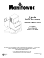
Q Model
AuCS® Accessory
(Automatic Cleaning System)
Installation
Owner/Operator
Use and Care Guide
This manual covers installation and use and care information for the Q Model AuCS® accessory ONLY.
If you are installing the AuCS® accessory on any other Manitowoc Ice Machine,
order manual Part Number 80-0885-3
We reserve the right to make product improvements at any time.
Specifications and design are subject to change without notice.
Part Number 80-1107-3
9/97
Safety Notices
Procedural Notices
When installing or using the Q Model AuCS®
accessory, be sure to pay close attention to the safety
notices in this manual. Disregarding the notices may
lead to serious injury and/or damage to the ice
machine or AuCS® accessory.
When installing or using the Q Model AuCS®
accessory, be sure to read the procedural notices in
this manual. These notices supply helpful and
important information.
Throughout this manual, you will see the following
types of safety notices:
WARNING
Text in a Warning box alerts you to a potential
personal injury situation. Be sure to read the
Warning statement, and then proceed carefully.
CAUTION
Text in a Caution box alerts you to a situation in
which you could damage the ice machine or AuCS®
accessory. Be sure to read the Caution statement,
and then proceed carefully.
CAUTION
Use only Manitowoc approved Ice Machine
Cleaner (part number 94-0546-3) and Sanitizer
(part number 94-0565-3) with the AuCS®
accessory.
Read and understand all information printed on the
bottles before use.
Throughout this manual, you will see the following
types of procedural notices:
Important
Important boxes serve two functions:
They call the operator’s attention to important
information.
They also provide the service technician with
information that may help in performing a
procedure more efficiently. Disregarding this
information may slow down the work.
NOTE: Text set off as a Note provides you with
simple, but useful, extra information.
Table of Contents
Table of Contents
Section 1 - General Information
Freight Damage and Claims Procedure......................................................................................................... 1-1
Model/Serial Number Location ...................................................................................................................... 1-1
Owner Warranty Registration Card.............................................................................................................. 1-2
Warranty Coverage ......................................................................................................................................... 1-2
Component Location and Identification........................................................................................................ 1-3
Section 2 - Installation Instructions
General.............................................................................................................................................................. 2-1
Electrical Service.............................................................................................................................................. 2-1
Location/Mounting .......................................................................................................................................... 2-2
Connection to Ice Machine.............................................................................................................................. 2-4
Determine Type of Solution Needed............................................................................................................... 2-10
Installing Bottle of Solution ............................................................................................................................ 2-10
Changing Solution Type .................................................................................................................................. 2-11
Hose Priming .................................................................................................................................................... 2-11
Setting Frequency of Cleaning........................................................................................................................ 2-12
Removal From Service/Winterization ........................................................................................................... 2-12
Section 3 - Operation
Automatic Operation....................................................................................................................................... 3-1
Manual Start Operation.................................................................................................................................. 3-1
Changing Switch Position During Automatic Operation............................................................................. 3-2
i
Table of Contents
THIS PAGE INTENTIONALLY LEFT BLANK
ii
Section 1
General Information
Section 1
General Information
Freight Damage and Claims
Procedures
1. Shortages
Check the number of cartons delivered against the
quantity shown on your receipt. If the quantities
do not match, have the driver note the shortage
and file your claim with the freight company.
2. No-Fault Claim Procedure
Manitowoc assumes responsibility for all freight
damage claims involving participating carriers,
with the following exceptions:
• When the trucking company loses the
equipment.
• When fire destroys the equipment en route.
• When a traffic accident damages the shipment
en route.
3. Visible Damage
A. If a carton appears damaged in any way, open
the carton and inspect the contents in the
presence of the driver. Note the nature and
extent of the damage on the freight bill.
B. Notify your local Manitowoc distributor to
inspect the merchandise within 15 days of
delivery. Do not attempt to repair the damage.
4. Concealed Damage
A. If damage is noticed at the time of
installation, notify the distributor immediately
and ask for an inspection.
B. Do not destroy packing materials until the
inspection is completed.
These conditions must be met before your claim
can be processed by the distributor.
5. Claims
Manitowoc Ice, Inc. and your local distributor
will arrange to repair or replace the equipment.
Model/Serial Number Location
Record the model and serial number of the AuCS®
accessory in the space provided below. These
numbers are required when requesting information
from your local Manitowoc distributor, service
representative, or Manitowoc Ice, Inc.
The model and serial number are listed on the
OWNER WARRANTY REGISTRATION CARD.
They are also listed on the MODEL/SERIAL
NUMBER DECAL affixed to the side of the AuCS®
accessory.
MODEL AND
SERIAL NUMBER
PLATE
SV1275
Model/Serial Number Location
Ice Machine
Bin/Dispenser
Remote
Condenser
AuCS®
Accessory
Model Number
Serial Number
Model Number
Serial Number
1-1
General Information
Section 1
Owner Warranty Registration Card
GENERAL
The packet containing this manual also includes
warranty information. Warranty coverage begins the
day your new AuCS® accessory is installed.
Important
Complete and mail the OWNER WARRANTY
REGISTRATION CARD as soon as possible to
validate the installation date.
If you do not return your OWNER WARRANTY
REGISTRATION CARD, Manitowoc will use the
date of sale to the Manitowoc distributor as the first
day of warranty coverage for your new AuCS®
accessory.
Warranty Coverage
GENERAL
The following Warranty outline is provided for your
convenience.
Contact your local Manitowoc representative or
Manitowoc Ice, Inc. if you need further warranty
information.
PARTS
Manitowoc warrants the AuCS® accessory against
defects in materials and workmanship, under normal
use and service for three (3) years from the date of
original installation.
LABOR
Labor required to repair or replace defective
components is covered for three (3) years from the
date of original installation.
1-2
EXCLUSIONS
The following items are not included in the ice
machine’s warranty coverage:
1. Normal maintenance, adjustments and cleaning as
outlined in this manual.
2. Repairs due to unauthorized modifications to the
ice machine or the AuCS® accessory, or the use
of non-standard parts without prior written
approval from Manitowoc Ice, Inc.
3. Damage caused by improper installation of the
ice machine, AuCS® accessory, electrical supply,
water supply or drainage, or damage caused by
floods, storms, or other acts of God.
4. Premium labor rates due to holidays, overtime,
etc.; travel time; flat rate service call charges;
mileage and miscellaneous tools and material
charges not listed on the payment schedule.
Additional labor charges resulting from the
inaccessibility of the ice machine and AuCS®
accessory are also excluded.
5. Parts or assemblies subjected to misuse, abuse,
neglect or accidents.
6. Damage or problems caused by installation,
cleaning and/or maintenance procedures
inconsistent with the technical instructions
provided in this manual.
AUTHORIZED WARRANTY SERVICE
To comply with the provisions of the warranty, a
refrigeration service company, qualified and
authorized by a Manitowoc distributor, or a
Contracted Service Representative must perform the
warranty repair.
NOTE: If the dealer the ice machine and AuCS®
accessory were purchased from is not authorized to
perform warranty service, contact the Manitowoc
distributor or Manitowoc Ice, Inc. for the name of the
nearest authorized service representative.
Section 1
General Information
Component Location and Identification
MOUNTING SLOTS
DISPENSING PUMP
MODULAR WIRE LEAD
(9 FEET LONG)
VINYL TUBE
(9 FEET LONG)
VINYL TUBE
CONTROL
BOARD
PLASTIC CAP
ELECTRIC POWER CORD
(8 FEET LONG)
PUMP
OSCILLATING
DIODE
SV1630G
12 34
0
5
9
8 76
MODULAR FEMALE
CONNECTOR
CLEANING FREQUENCY
SELECTOR SWITCH
LED LIGHT
RELAY
ELECTRIC CORD FOR
POWER TO AuCS®
ELECTRIC CORD TO
DISPENSING PUMP
CONTROL
BOARD
SV1631G
Component Location/Identification
1-3
General Information
THIS PAGE INTENTIONALLY LEFT BLANK
1-4
Section 1
Section 2
Installation Instructions
Section 2
Installation Instructions
General
Electrical Service
These instructions are provided to assist the qualified
installer. Check your local yellow pages for the name
of the nearest Manitowoc Ice Machine Distributor or
call Manitowoc Ice, Inc. for information regarding
installation and start-up services.
WARNING
Improper installation will affect dispensing rate.
Install only within the parameters outlined in this
installation manual.
Please contact your local Manitowoc Distributor or
call Manitowoc Ice, Inc. for assistance if you
encounter a problem that is not covered by this
manual.
3-7/16”
12”
WARNING
All wiring must conform to local, state, and
national codes.
Voltage/Cycle/
Phase
115/60/1
220/240/50/1
Runnin
g Amps
.3
.1
N.E.M.A Electrical Plug
Configuration
5-15P
No plug attached
115 VOLT WIRING
The 115/60/1 AuCS® has an eight (8) foot cord
which must be plugged into a 15 amp electrical
outlet.
CAUTION
Never use an extension cord. If an outlet is not in
reach of the AuCS® power cord, have an outlet
installed.
220/240 VOLT WIRING
The 220/240/50/1 AuCS® must be wired to the
terminal block located in the ice machine.
12-1/8”
9’
8’
SV1632G
Dimensions
PRE-WIRED TO ICE MACHINE
TERMINAL BLOCK LOCATED
IN ICE MACHINE
L1
L1
N
N
GROUND
GROUND
TO SEPARATE FUSE/
CIRCUIT BREAKER.
DISCONNECT ALL POLES.
REFER TO ICE MACHINE
INSTALLATION
INSTRUCTIONS FOR
FUSE RATING.
N
L1
AuCS® POWER
CORD
®
PRE-WIRED AT AuCS ACCESSORY
SV1633G
220/240/50/1 Wiring
2-1
Installation Instructions
Location/Mounting
CAUTION
Do not install in an area where the air temperature
falls below 35°F or exceeds 110°F.
The AuCS® must be protected if it will be subjected
to temperatures below freezing. Refer to “Removal
From Service/Winterization.”
HEIGHT REQUIREMENT
(Refer to drawing on page 2-3.) Either the base or the
top of the AuCS® must be within 2” of the base of the
ice machine. Do not mount the AuCS® too high or
too low.
Section 2
3. Align the AuCS® key slots with the mounting
bracket tabs. Verify the tabs are at the top of the
key slots and that the AuCS® is level.
4. Remove the backing from the adhesive bumpers
(part D, page 2-4.) Attach bumpers to the
mounting bracket directly above the AuCS®
control box. This eliminates upward movement
and stops the tabs from disengaging the key slots.
CAUTION
The cleaner or sanitizer may siphon (or dispense
improperly)into the ice machine water trough if the
AuCS® is mounted too high or too low.
DISTANCE REQUIREMENT
(Refer to drawing on page 2-3.) The AuCS® must be
mounted within 9 feet of the ice machine to
accommodate the low voltage modular wire and
tubing. The tubing may be shortened to accommodate
a run of less than 9 feet.
CAUTION
Do not extend the length of the 9-foot low voltage
modular wire or tubing. The correct amount of
solution will not dispense.
GASKET
BRACKET
BUMPER
SV1640G
Mounting to Ice Machine
FASTENING TO WALL
The AuCS® is mounted to the wall using the two key
slots in the back wall of the accessory. Screw
fasteners (not supplied) must hold the entire weight
of the AuCS® accessory (approximately 10 lb.).
6-9/16”
FASTENING TO BIN OR DISPENSER
CAUTION
The AuCS accessory may be mounted to the bin
or dispenser only when permitted by local electrical
codes.
®
NOTE: The ice machine’s serviceability may be
reduced when the AuCS® is mounted to the bin or
dispenser. Wall mounting is recommended.
1. Set the mounting bracket (part F, page 2-4) over
the bin top rail at desired location (refer to
figure).
2. Remove the backing from the foam adhesive tape
(part E, page 2-4). Apply tape to mounting
bracket, and along the entire bin rail.
2-2
SV1634G
Key Slot Dimensions
Section 2
Installation Instructions
BASE OF ICE MACHINE
NO! TOO HIGH
2”
2”
BOX BASE OR BOX TOP
MUST BE WITHIN 2” OF
ICE MACHINE BASE
NO! TOO LOW
NOTE: BOX MUST ALSO MOUNT WITHIN REACH OF 9’ TUBING AND LOW VOLTAGE MODULAR WIRE.
SV1639G
Height and Distance Requirements
2-3
Installation Instructions
Section 2
Connection to Ice Machine
GENERAL
PVC CONDUIT FITTING (A) INSTALLATION
A
½” PVC CONDUIT
FITTING
B
HOSE CLAMPS
C
LOCKNUT
D
BUMPER
½” LOCKNUT (C)
½” PVC CONDUIT
FITTING (A)
SV1636G
PVC Conduit Fitting (A) Installation
1. Insert the PVC fitting (A) into the AuCS® and
tighten with the lock nut (C).
E
FOAM TAPE
F
BRACKET
SV1635G
Parts Identification
2-4
WARNING
Disconnect the electric power supply to the ice
machine at the electrical disconnect before
proceeding.
2. If required for access, remove the front, top, and
right side panels from the ice machine.
3. Remove the 7/8” access hole plug located on the
back of the corner post of the ice machine
4. Insert the PVC conduit fitting (Part A) and
tighten with the lock nut (Part C).
Section 2
Installation Instructions
Connection to Ice Machine (cont.)
Q200 Q450 Q600 Q800
Q1000 Q1300 Q1800
Q320 Q420
1-1/8” DIAMETER
ACCESS HOLE
1-1/8” DIAMETER
ACCESS HOLE
5”
3”
1.5”
1.5”
½” PVC CONDUIT
FITTING (A)
½” LOCKNUT (C)
½” LOCKNUT (C)
½” PVC CONDUIT
FITTING (A)
SV1637G
PVC Conduit Fitting (A) Installation
2-5
Installation Instructions
Section 2
Connection to Ice Machine (cont.)
PVC CONDUIT CONNECTION
(NOT SUPPLIED)
Connect the ½” PVC conduit from the AuCS® to the
ice machine.
CAUTION
Install 1/2” conduit to protect the tubing and
modular wire from damage or access.
NOTE: AuCS® SHOWN
IS 115 VOLT WITH
POWER CORD
ATTACHED
NOTE: A pulling elbow is recommended for easier
routing of the vinyl tubing and modular wire.
SV1638G
Typical PVC Conduit Installation
2-6
Section 2
Installation Instructions
Connection to Ice Machine (cont.)
WATER INLET
VALVE
ACCESS
HOLE
WATER INLET
BARBED FITTING
SV1641G
Vinyl Tubing Installation (Typical Q450 Shown)
2-7
Installation Instructions
Section 2
Connection to Ice Machine (cont.)
MODULAR WIRE CONNECTION
Insert the low voltage modular wire through the ½”
conduit connecting the AuCS® to the ice machine.
Plug into the jacks on the ice machine control board
and the AuCS® control board. (Refer to drawing for
routing modular wire in ice machine.)
CONTROL BOARD
MODULAR
WIRE
GROUND WIRE
(Q1300/Q1800 ONLY)
ROUTE WIRING
THROUGH
ACCESS HOLES
AS SHOWN
MODULAR
WIRE
Q450
Q320/Q420
SV1642G
Low Voltage Modular Wire Connection
2-8
Section 2
Installation Instructions
Connection to Ice Machine (cont.)
VINYL TUBING CONNECTION
1. Insert the tubing into the ½” conduit from the
AuCS® to the ice machine.
2. Slide the 3/8” hose clamp (B) onto the tubing and
connect it to the barbed fitting on the AuCS®
dispenser pump.
AuCS® INLET
WATER INLET
3/8” HOSE CLAMP (B)
8’ VINYL TUBING
SV1644G
MODULAR WIRE LEAD
SV1643G
Connecting Vinyl Tubing to Dispenser Pump
Using 3/8” Hose Clamp (B)
3. Route the tubing through the bulkhead heyco
fitting and into the water compartment.
4. Determine the amount of tubing required and cut
off the excess.
5. Slide the 3/8” hose clamp (Part B) onto the tubing
and connect it to the water inlet barbed fitting.
Connecting Vinyl Tubing to
Water Inlet Barbed Fitting
AFTER INSTALLATION
WARNING
Read and understand this entire manual prior to
operation of the AuCS® accessory. You must
understand all warning and caution statements and
follow all safety precautions to assure proper
operation of the AuCS® accessory.
2-9
Installation Instructions
Determine Type Of Solution Needed
CAUTION
Use only Manitowoc-approved Ice Machine
Cleaner (part number 94-0546-3) or Sanitizer (part
94-0565-3) in the AuCS®. It is a violation of
Federal law to use these solutions in a manner
inconsistent with their labeling. Read and
understand all labels on the bottles before use.
The AuCS® accessory will dispense Cleaner OR
Sanitizer. It cannot dispense both at the same time.
CAUTION
Do not mix Cleaner and Sanitizer solutions
together. It is a violation of Federal law to use these
products in a manner inconsistent with their
labeling.
Section 2
Installing Bottle Of Solution
WARNING
Wear rubber gloves and safety goggles (and/or face
shield) when handling Cleaner or Sanitizer.
CAUTION
Follow instructions listed under “Changing
Solution Type” on the next page when changing
from Cleaner to Sanitizer or from Sanitizer to
Cleaner.
1. Place the bottle into the AuCS® accessory.
2. Slide the tube to the bottom of the bottle and
hand-tighten the cap.
MANITOWOC ICE MACHINE CLEANER
Part Number 94-0546-3
Ice Machine Cleaner is used to control build-up and
to remove lime scale or other mineral deposits. It will
not “sanitize” the ice machine.
It is recommended for use in places that have lime
scale or other mineral deposits built up, but no
problems with slime.
MANITOWOC ICE MACHINE SANITIZER
Part Number 94-0565-3
Ice Machine Sanitizer is used for sanitizing and
controlling algae build-up (slime) and other bacterial
growth. The ice machine should be sanitized on a
regular schedule, following Manitowoc
recommendations and local regulations.
It is recommended for use in places such as pizzerias,
bars, bakeries, etc., that have airborne bacteria
(yeast). Sanitizing is also recommended in places that
do not have lime scale (or other mineral deposit
problems).
Model
Amount of Cleaner or
Sanitizer Dispensed
Q200 Q320 Q420 Q450
*2.4 ounces (70 ml)
Q600 Q800 Q1000
Q1300 Q1800
*4.8 ounces (140 ml)
*The dispense rate is automatically controlled
2-10
TUBE MUST BE CLOSE
TO BOTTLE BOTTOM
SV1645
Bottle Installation
Section 2
Changing Solution Type
CAUTION
Do not mix Cleaner and Sanitizer solutions
together. It is a violation of Federal law to use these
products in a manner inconsistent with their
labeling.
Use the following procedure to flush the system prior
to changing from Cleaner to Sanitizer or from
Sanitizer to Cleaner.
1. Remove the bottle of Cleaner or Sanitizer from
the AuCS®. Insert a 16 oz. bottle of water.
2. Repeat the following until the water bottle is
empty (approximately 8 times):
A. Move the ice machine toggle switch to
CLEAN.
B. The water pump and dump valve will turn on.
The dump valve will shut off after
approximately 45 seconds.
C. The pump will dispense for 10-20 seconds.
(The Q1300 and Q1800 will dispense for
30-40 seconds).
D. Move the switch to OFF after step C is
completed.
3. Install a new bottle of either Cleaner or Sanitizer
solution. Refer to “Installing Bottle of Solution”
on previous page.
Installation Instructions
Hose Priming
The dispenser pump requires priming only upon
initial installation, or if the hose between the AuCS®
and the ice machine has been pumped dry.
WARNING
Do not blow into or suck on the hose in an attempt
to prime it.
CAUTION
Do not prime the hose until installation is complete.
Repeat the following procedure three times:
1. Move the ice machine toggle switch to CLEAN.
2. The water pump and dump valve will turn on.
The dump valve will shut off after approximately
45 seconds.
3. The pump will dispense for 10-20 seconds. (The
Q1300 and Q1800 will dispense for 30-40
seconds).
4. Move the switch to OFF after step 3 is completed.
Important
The priming procedure starts the automatic
cleaning mode. Upon moving the ice machine
toggle switch to ICE, the ice machine will run
through 6 rinse cycles before making ice.
2-11
Installation Instructions
Setting Frequency Of Cleanings
The AuCS®is factory-set to clean (or sanitize) the ice
machine approximately once every two weeks. For
less frequent cleaning, set the selector switch as
indicated below. (Refer to “Component Location and
Identification” for selector switch location.)
Switch
Position
0
Time Between
Cleanings
No cleaning (OFF)
Approximately 2 weeks
(1120 harvests)
Approximately 4 weeks
(2240 harvests)
Approximately 12 weeks
(6720 harvests)
1
2
3
NOTE: Switch positions 4-9 are inoperative. Do not
use them.
Important
Using the AuCS accessory is supplemental to
regular cleaning and sanitizing (per Manitowoc
recommendations and local regulations).
®
2-12
Section 2
Removal From Service/Winterization
CAUTION
Leaving solutions in the AuCS® in freezing
temperatures may result in severe damage to the
dispensing pump. A failure of this nature is not
covered by the warranty.
If the AuCS® is to be removed from service for
extended periods, or if it is to be exposed to ambient
temperatures of 32°F (0°C) or below, follow this
procedure:
1. Remove the Cleaning or Sanitizing solution
bottle.
2. Follow the instructions under “Hose Priming” to
pump all of the solution out of the dispensing
pump and line.
Section 3
Ice Machine Operation
Section 3
Ice Machine Operation
Automatic Operation
Manual Start Operation
The following occurs when the toggle switch is in
the ICE position:
Step 1 Set the toggle switch to the OFF position
after ice falls from the evaporator at the end of a
Harvest cycle. Or, set the switch to the OFF
position and allow the ice to melt off the
evaporator.
•
•
•
The ice machine control board counts the
number of ice harvest cycles.
The AuCS® accessory interrupts the ice making
mode and starts the self-cleaning (or sanitizing)
mode when the harvest count equals the
“Frequency of Cleaning” setting of the AuCS®.
When the automatic self-cleaning(or sanitizing)
cycle is complete (approximately 25 minutes),
ice making resumes automatically, and the
“Harvest Count” is reset to zero.
Important
Opening the curtain switch will interrupt the
cleaning (or sanitizing) sequence. The sequence
will resume from the point of interruption when
the curtain recloses.
NOTE: The harvest count is reset after the AuCS®
cycle is completed. It cannot be reset by unplugging
the modular wire, changing the switch position,
power loss, etc.
CAUTION
Never use anything to force ice from the
evaporator. Damage may result.
Step 2 To start the automatic cleaning system,
move the toggle switch to the CLEAN position. The
water will flow through the water dump valve and
down the drain. The Clean light will turn on to
indicate the ice machine is in the Self-Cleaning
Mode. The AuCS® then automatically adds cleaner
or sanitizer to the ice machine.
Step 3 The ice machine will automatically time out
a ten minute cleaning or sanitizing cycle, followed
by six rinse cycles, de-energize the Clean light and
stop. This entire cycle lasts approximately 25
minutes.
Step 4 After the cleaning or sanitizing cycle stops,
move the toggle switch to ICE position.
Step 5 The ice machine may be set to start and
finish a self-cleaning (or sanitizing) cycle, then
automatically start ice making again.
You must wait about one minute into the cleaning
cycle (until water starts to flow over the
evaporator), then move the toggle switch from
CLEAN to ICE position.
When the self-cleaning cycle (or sanitizing) is
completed, an ice making sequence will start
automatically.
3-1
Ice Machine Operation
Section 3
Changing Switch Position During Automatic Operation
If the toggle switch is moved to OFF prior to the
pump dispensing (less than 45 seconds into the cycle)
then switched to:
ICE
CLEAN
If the toggle switch is moved to OFF after the 6 rinse
cycles have begun and then switched from off to:
ICE
A normal ice-making mode begins.
A manual clean cycle begins.
(See “Manual Start Operation,” page 3-1.)
If the toggle switch is moved to OFF after the pump
dispenses (more than 45 seconds into the cycle, but
before rinse cycles begin) then switched to:
ICE
CLEAN
The “clean” portion of the cycle begins.
After completion of the 10-minute
“Clean” and 6 rinse cycles, the counter
resets and a normal ice-making mode
begins.
A manual clean cycle begins.
(See “Manual Start Operation,” page 3-1.)
After completion of the 10-minute
“Clean” and 6 rinse cycles, the counter
resets and the ice machine awaits a
change in the toggle switch position.
3-2
CLEAN
The rinse portion of the cycle restarts and
continues.
After completion of the 6 additional rinse
cycles, the counter resets and a normal
ice-making mode begins.
A manual clean cycle begins.
(See “Manual Start Operation,” page 3-1.)
After completion of the 10-minute
“Clean” and 6 rinse cycles, the counter
resets and the ice machine awaits a
change in the toggle switch position.
Complete the following and retain for your records:
Distributor/Dealer ____________________________________________________________________
Model Number
____________________________
Serial Number
____________________________
Installation Date
____ / ____ / ____
MANITOWOC ICE, INC.
2110 South 26th Street P.O. Box 1720
Manitowoc, WI 54221-1720
Phone: (920) 682-0161
Fax: (920) 683-7585
Web Site - www.manitowocice.com
©1997 Manitowoc Ice, Inc.
Litho in U.S.A.