1
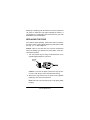
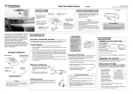
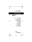
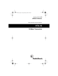
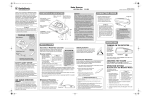
Please read before using this equipment. Owner’s Manual 360° Laser Radar Detector with VG-2 Guard Contents Features ................................................................................. 3 Safety Warning System ................................................... 4 A Quick Look ......................................................................... 6 Installation ............................................................................. 7 Selecting a Mounting Location ........................................ 7 Windshield Mounting ....................................................... 8 Hook-and-Loop Mounting ................................................ 9 Connecting Power ......................................................... 10 Calibrating the Electronic Compass ............................... 11 Operation ............................................................................. Turning On the Detector ................................................ Adjusting the Volume ..................................................... Using the Tutorial .......................................................... Operation Settings ......................................................... Selecting the City and Highway Modes .................. Selecting Display Brightness .................................. Muting the Audio Alert ............................................ Selecting VG-2 Mode ............................................. Receiving and Identifying Radar, Laser, and Safety Alert Signals ................................................ SWS Categories and Messages ............................ 12 12 13 13 14 14 14 15 15 15 16 Troubleshooting .................................................................. 20 Care and Maintenance ........................................................ 21 Replacing the Fuse ........................................................ 22 © 2000 Tandy Corporation. All Rights Reserved. RadioShack and RadioShack.com are trademarks used by Tandy Corporation. The compass technology used in this product is licensed under US patent numbers 4,851,777 and 5,239,264 from Precision Navigation, Inc. 2 Features Your RadioShack 360° Laser/Radar Detector can alert you to all known police traffic radar and laser systems with its distinct visual and audio alerts. It receives X-, K-, and Ka-band radar signals, and detects both the instant-on and laser systems many police departments use to measure vehicle speed. Your detector can also give you advance warning of potential road hazards by detecting signals from transmitters that broadcast Safety Warning System alerts. Note: Before reading this Owner’s Manual read the supplied booklet Questions and Answers About Vehicle Speed Detection to familiarize yourself with the terms. Your detector’s features include: Electronic Compass — provides accurate heading information with alphanumeric display and LED panel. 360° Detection — detects laser signals from all around your vehicle. Ultralyte, X-, K-, Ka-Band, and Laser Signal Detection — warns you when it detects signals from traffic radar or laser devices. Different tones and visual indicators let you know the type of signal received. Safety Warning System Detection — alerts you to the presence of potential road hazards and emergency vehicles signaled by a Safety Warning System transmission. Features 3 VG-2 Protection — makes your detector invisible to the VG-2 radar-detector when it senses VG-2 operation. City/Highway Modes — let you minimize alerts when you are in areas that have false radar sources. City/Highway Selector and City/Highway Indicator — displays the mode currently selected. FAST (False Alert Suppression Technology) — helps prevent false alarms caused by non-traffic radar sources. Tutorial Mode — helps you learn to recognize the detector’s tones and displays. Memory Retention —holds settings in memory when you turn off power. Instant On or Pulse Radar — alerts you to sudden high level laser signals. SAFETY WARNING SYSTEM The Safety Warning System (SWS) is approved by the Federal Communications Commission (FCC) to operate on the 24.05– 24.25 GHz band for highway safety alerting and traffic signal control purposes. The Safety Warning System employs low-powered transmitters used by some emergency services and road crews to alert drivers to hazardous road conditions. The SWS can indicate many different emergency or hazardous conditions in the area (61 different messages are currently defined, with 3 additional for future use). 4 Features The system has the potential to dramatically decrease the occurrence of traffic accidents by increasing drivers’ awareness of local road hazards. Having this safety alert compatible radar/laser detector will ensure that you can benefit from this system wherever it is in use. Your radar/laser detector includes the following items: • coiled power cord • windshield bracket with suction cups • hook and loop tape • stand for hook and loop mounting • spare fuse • Booklet, Questions and Answers About Vehicle Speed Detection Important: Some areas have laws regulating the use of radar detectors. Check with your local law enforcement agency about the laws in your area. Features 5 A Quick Look DC 12V Jack 360° Laser Eye CITY MUTE DIM Display VOLUME/OFF LED Compass 360° Laser Eye — receives incoming laser signals directed at your vehicle from all directions DC 12V Jack — the power cord connection DIM — controls the brightness of the display MUTE — silences the alert tone for about 20 seconds after the current signal is lost CITY (City/Highway) — switches between the city and highway modes LED Compass — indicates your heading information VOLUME/OFF — lets you turn the detector on and off and adjust the volume 6 A Quick Look Display — indicates the mode (City/Highway), type of signal, signal strength, and compass heading for detected signals. Installation SELECTING A MOUNTING LOCATION For the best performance, select a location for the detector where it has a direct view of the road. The detector’s radar antenna is located at the opposite end from the display. • Choose a location that does not block the driver’s view of the road. • Mount the detector in a level position with a clear view to both the front and rear of your vehicle and insure its view of the road is not blocked by any metal object. • Some vehicles have InstaClear or ElectriClear defogging windshields, which have metal coatings that block signals. Some vehicles have a solar shield that block signals. Check your vehicle’s owner’s manual to see if your vehicle has any of these features. A detector installed in a vehicle with any of these features might not detect a signal. • Since window tinting reduces the received strength of laser signals, you should not mount the detector behind any tinted glass. • Do not mount the detector where the driver or a passenger might hit it in a sudden stop or accident. Installation 7 Caution: When not in your vehicle, place your detector out of view to help discourage theft and to protect it from high temperatures. Note: Though the detector has a 360° laser and radar detection range, radar detection is more sensitive in the front range. WINDSHIELD MOUNTING The supplied suction-cup windshield bracket lets you easily mount the detector on the windshield. Caution: Do not use the bracket in a vehicle that has a plastic coating on the windshield designed to protect passengers during an accident. If you use the bracket on this type of windshield, you might permanently mar the windshield's surface. For an alternative mounting method, see (“Hook-and-Loop Mounting” on Page 9.) 1. Clean the selected windshield area, position the bracket on the windshield, and press firmly on each suction cup to secure it in place. 2. Slide the detector onto the base plate until it snaps into place. VOLUME/OFF Base Plate 8 Installation 3. To adjust the mounting angle, remove the detector from the bracket. Then remove the bracket from the windshield and adjust it by carefully bending it. HOOK-AND-LOOP MOUNTING In some vehicles, the dashboard may be the best location to mount the detector. For this mounting, use the supplied hookand-loop tape as follows: 1. Use a damp cloth to clean the bottom of the stand and the dashboard. Let both surfaces dry. Note: The tape’s adhesive might not stick to a surface treated with vinyl cleaner or protector. 2. Attach the stand to the bottom of the detector using the two tabs on the stand. Locate the tabs over the two openings on the detectors base and press down. Note: After attaching the stand, to remove it, press on the tab until it clicks and remove the stand. Installation 9 3. Remove the tape’s paper backing and stick the tape to the bottom of the stand. Tabs Hook and Loop Tape Stand 4. Remove the paper backing from the other side of the tape and press your detector onto the dashboard. CONNECTING POWER Caution: • Use only the supplied power cord. If your power cord is lost or damaged, you can order a replacement cord from your local RadioShack store. • Before plugging the power cord’s cigarette-lighter plug into your vehicle’s cigarette-lighter socket, make sure the plug’s tip is screwed firmly onto the plug. See “Replacing the Fuse” on Page 22 for more information about the cigarettelighter plug. 10 Installation • Unplug the power cord’s plug from the vehicle’s cigarettelighter socket when you turn off the ignition. This prevents the vehicle’s battery from being drained if the detector is left on when the ignition is turned off. Plug the supplied power cord’s barrel plug into the detector’s DC 12V jack. Then plug the cord’s cigarette-lighter plug into your vehicle’s cigarette-lighter socket. Note: If the detector does not operate, remove the cigarettelighter plug from your vehicle’s cigarette-lighter socket and check the socket for ashes and other debris. Also, check the fuse in the cigarette-lighter plug and your vehicle’s fuse block (see “Replacing the Fuse” on Page 22). CALIBRATING THE ELECTRONIC COMPASS Your radar detector has an electronic compass that can display eight kinds of headings: North (N), East (E), South (S), West (W), Northeast (NE), Northwest (NW), Southeast (SE), and Southwest (SW). Note: The detector displays the compass heading information until it picks up a signal. After the detector displays the signal, it returns to the compass display. After installing the detector in your vehicle, you must calibrate the electronic compass before using it. Calibration separates the earth’s magnetic field from other magnetic fields so that the electronic compass provides accurate heading information. Installation 11 You must calibrate the detector when: • It is being used for the first time. • It is moved to a different location within the vehicle, or if it is removed and placed in another vehicle. • DISTORT appears. Note: You must complete the circles in less than 2 minutes. Otherwise, begin again from step1. Follow these steps to calibrate your detector. 1. Hold down CITY for about 2 seconds until CAL.... appears. TURN and TWICE flash alternately. 2. Turn the steering wheel all the way to the right or left and drive in two complete circles. Then press CITY. WAIT flashes four times. 3. If the calibration is complete, SUCCESS! appears. If calibration is not, the display scrolls PLEASE CALIBRATE AGAIN... PRESS CITY-KEY. Repeat steps 1 and 2. After calibration, the compass heading appears. Operation TURNING ON THE DETECTOR To turn on the detector, rotate VOLUME/OFF toward VOLUME until it clicks. A tone sounds and WELCOME appears. After self12 Operation testing, heading information and HWY appear. (See “Selecting the City and Highway Modes” on Page 14.) To turn off the detector, rotate VOLUME/OFF toward OFF until it clicks and the display turns off. ADJUSTING THE VOLUME Rotate VOLUME/OFF toward VOLUME to increase volume, or toward OFF to decrease volume. USING THE TUTORIAL Use the tutorial mode to familiarize yourself with the display. 1. Hold down DIM and CITY (at the same time) then turn on the detector. TUTORIAL and MODE flash alternately. 2. To see each alert demonstrated, press DIM. The detector displays each alert and sounds its corresponding audio alert in the following order. 1. X-Band Alert 7. Rock Slide Area Ahead 2. K-Band Alert 8. School Zone Ahead 3. Ka-Band Alert 9. Road Narrows Ahead 4. Laser Alert 10. Sharp Curve Ahead 5. Ultralyte Laser Alert 11. Pedestrian Crossing Ahead 6. VG-2 Alert 3. To end the tutorial at any time, press MUTE. Operation 13 OPERATION SETTINGS Selecting the City and Highway Modes Your detector has two operating modes: city and highway. In city mode, the detector requires a stronger X-, K-, or Ka-band signal before it sounds or displays an alert. Notes: • City mode helps prevent false alerts in highly populated areas, where radar signals can bounce off surrounding structures. • The city mode has no effect on laser alerts or instant-on radar. The highway mode provides maximum sensitivity for open-road driving. The detector is preset to highway mode and HWY appears on the display when you turn it on. To select the city mode, press CITY. CTY appears. To return to the highway mode, press CITY again and HWY appears. Selecting Display Brightness You can select from three levels of brightness: bright, dim, and dark. The display is preset to bright. Pressing DIM once reduces the display's brightness by half. Pressing DIM a second time reduces the display's brightness by 90%. Pressing DIM a third time returns display to full brightness. 14 Operation Muting the Audio Alert When the detector sounds a radar or safety alert signal, press MUTE to temporarily silence the detector. When you press MUTE, M appears. The detector resets MUTE to go off 20 seconds after the signal stops. Or, press MUTE again before it resets, and M disappears. The laser alert signal remains audible even if you press MUTE. Selecting VG-2 Mode VG-2 mode is preset to off. To turn on VG-2, hold down MUTE until VG2-ON appears. To turn VG-2 off, hold down MUTE until VG2-OFF appears. Note: If there is another detector nearby, you might receive false signals. To avoid receiving such signals, turn VG-2 off. RECEIVING AND IDENTIFYING RADAR, LASER, AND SAFETY ALERT SIGNALS When your detector senses a radar signal, X, K, or KA appears. An alert tone for the type of band detected sounds, and the display shows the signal strength in numeric form. Note: The closer you get to the source of the radar, the higher the signal strength number. When your detector senses an instant-on signal, INSTANT ON appears and the instant-on alert tone sounds. When your detector senses a laser signal, LASER flashes and the laser alert tone sounds. Operation 15 When your detector senses an Ultralyte laser signal, ULTRALYTE LASER scrolls and the Ultralyte laser alert tone sounds. When your detector senses a VG-2 signal, VG-2 appears and the VG-2 alert tone sounds. When your detector senses a SWS signal, a message describing the detected signal appears and an alert tone sounds. SWS Categories and Messages Category 1: Highway Construction Maintenance WORK ZONE AHEAD ROAD CLOSED AHEAD/FOLLOW DETOUR BRIDGE CLOSED AHEAD/FOLLOW DETOUR HIGHWAY WORK CREW AHEAD UTILITY WORK CREW AHEAD ALL TRAFFIC FOLLOW DETOUR AHEAD ALL TRUCKS FOLLOW DETOUR AHEAD ALL TRAFFIC EXIT AHEAD RIGHT LANE CLOSED AHEAD CENTER LANE CLOSED AHEAD LEFT LANE CLOSED AHEAD 16 Operation Category 2: Highway Hazard Zone Advisory I STATIONARY POLICE VEHICLE AHEAD TRAIN APPROACHING/AT CROSSING LOW OVERPASS AHEAD DRAW BRIDGE UP OBSERVE BRIDGE WEIGHT LIMIT ROCK SLIDE AHEAD SCHOOL ZONE AHEAD ROAD NARROWS AHEAD SHARP CURVE AHEAD PEDESTRIAN CROSSING AHEAD Category 3: Highway Hazard Zone Advisory II DEER/MOOSE CROSSING BLIND/DEAF CHILD AHEAD STEEP GRADE AHEAD/TRUCK USE LOW GEAR ACCIDENT AHEAD POOR ROAD SURFACE AHEAD SCHOOL BUS LOADING/UNLOADING NO PASSING ZONE DANGEROUS INTERSECTION AHEAD STATIONARY EMERGENCY VEHICLE AHEAD Operation 17 Category 4: Weather Related Hazards HIGH WIND AHEAD SEVERE WEATHER AHEAD HEAVY FOG AHEAD HIGH WATER/FLOODING AHEAD ICE ON BRIDGE AHEAD ICE ON ROAD AHEAD BLOWING DUST AHEAD BLOWING SAND AHEAD BLOWING SNOW WHITE OUT AHEAD Category 5: Travel Information/Convenience I REST AREA AHEAD REST AREA WITH SERVICE AHEAD 24 HOUR FUEL SERVICE AHEAD INSPECTION STATION OPEN INSPECTION STATION CLOSED REDUCE SPEED AREA AHEAD SPEED LIMIT ENFORCED HAZARDOUS MATERIALS EXIT AHEAD CONGESTION AHEAD/EXPECT DELAY EXPECT 10 MINUTE DELAY 18 Operation Category 6: Travel Information/Convenience II EXPECT 20 MINUTE DELAY EXPECT 30 MINUTE DELAY EXPECT 1 HOUR DELAY TRAFFIC ALERT/TURN ON AM RADIO PAY TOLL AHEAD TRUCKS EXIT RIGHT TRUCKS EXIT LEFT Category 7: Fast/Slow Moving Vehicles EMERGENCY VEHICLE IN TRANSIT POLICE IN PURSUIT OVERSIZED VEHICLE IN TRANSIT SLOW MOVING VEHICLE Operation 19 Troubleshooting If you have problems operating your detector, these suggestions might help. If you cannot solve the problem after trying these suggestions, take your detector to your local RadioShack store for assistance. Problem The detector does not turn on. Suggestion Be sure all power connections are secure. The cigarette-lighter socket might be dirty. Clean it with fine emery cloth to ensure a good, clean connection. Check the fuse in the power cord’s cigarettelighter plug. See “Replacing the Fuse” on Page 22. Check the fuse that controls power to your vehicle’s cigarette-lighter socket. See your vehicle’s owner’s manual. Caution: Do not place any metal object other than the cigarette lighter or cigarette-lighter plug in the cigarette-lighter socket. Doing so could blow a fuse in your vehicle or cause the metal object to become very hot. The detector gives a false alert when you use vehicle accessories such as power windows, motorized mirrors, brakes, and so on. 20 Check the vehicle's electrical system for loose connections, including the main battery cable and alternator connections. Install a filter capacitor 1000 µF, 35 Volts, on the back of the cigarette-lighter socket, across the power connections. Troubleshooting Problem The detector performs the self-test, but does not respond to radar signals when you see a police car. The detector has poor laser detection range. Suggestion A police car might not be equipped with radar (see the supplied booklet, Questions and Answers About Vehicle Speed Detection). Police might be using VASCAR-type speed detection (see the supplied booklet, Questions and Answers About Vehicle Speed Detection). Be sure the laser detection lens is not blocked. Be sure the detector is properly mounted. See “Selecting a Mounting Location” on Page 7. Use lens-cleaning solution to clean the laser detection lens. Care and Maintenance To enjoy your RadioShack 360° Laser/Radar Detector for a long time: • Keep the detector dry. If it gets wet, wipe it dry immediately. • Use and store the detector only in normal temperature environments. • Handle the detector gently and carefully. Do not drop it. • Keep the detector away from dust and dirt. • Wipe the detector with a damp cloth occasionally to keep it looking new. Care and Maintenance 21 Modifying or tampering with the detector’s internal components can cause a malfunction and might invalidate its warranty. If your detector is not performing as it should, take it to your local RadioShack store for assistance. REPLACING THE FUSE If the detector stops operating, follow these steps to check the fuse in the power cord's cigarette-lighter plug and replace it with a 2-amp, 11/4 × 1/4 fast-acting fuse. Caution: Using a fuse that does not meet the requirements above can damage your detector, the power cable, or the vehicle's electrical system. 1. Turn the knurled ring end plug counter-clockwise on the cigarette-lighter adapter to unscrew it. Knurled Ring Fuse Caution: If you must use pliers to loosen the ring, be careful not to crush the ring or the metal tip inside the ring. 2. Remove the ring and tip from the power cord’s cigarette lighter plug, then remove the old fuse. Note: Take care not to lose the ring, tip, or the spring inside the plug. 22 Care and Maintenance 3. Check the fuse. If it has blown, replace it. 4. Replace the metal tip inside the ring, making sure the spring is intact, then place the fuse inside the adapter and screw the ring back onto the adapter. Make sure the tip is visible when you reassemble the adapter. Caution: Never use pliers or other tools to retighten the ring on the cigarette-lighter plug. Care and Maintenance 23 Limited One-Year Warranty This product is warranted by RadioShack against manufacturing defects in material and workmanship under normal use for one (1) year from the date of purchase from RadioShack company-owned stores and authorized RadioShack franchisees and dealers. EXCEPT AS PROVIDED HEREIN, RadioShack MAKES NO EXPRESS WARRANTIES AND ANY IMPLIED WARRANTIES, INCLUDING THOSE OF MERCHANTABILITY AND FITNESS FOR A PARTICULAR PURPOSE, ARE LIMITED IN DURATION TO THE DURATION OF THE WRITTEN LIMITED WARRANTIES CONTAINED HEREIN. EXCEPT AS PROVIDED HEREIN, RadioShack SHALL HAVE NO LIABILITY OR RESPONSIBILITY TO CUSTOMER OR ANY OTHER PERSON OR ENTITY WITH RESPECT TO ANY LIABILITY, LOSS OR DAMAGE CAUSED DIRECTLY OR INDIRECTLY BY USE OR PERFORMANCE OF THE PRODUCT OR ARISING OUT OF ANY BREACH OF THIS WARRANTY, INCLUDING, BUT NOT LIMITED TO, ANY DAMAGES RESULTING FROM INCONVENIENCE, LOSS OF TIME, DATA, PROPERTY, REVENUE, OR PROFIT OR ANY INDIRECT, SPECIAL, INCIDENTAL, OR CONSEQUENTIAL DAMAGES, EVEN IF RadioShack HAS BEEN ADVISED OF THE POSSIBILITY OF SUCH DAMAGES. Some states do not allow limitations on how long an implied warranty lasts or the exclusion or limitation of incidental or consequential damages, so the above limitations or exclusions may not apply to you. In the event of a product defect during the warranty period, take the product and the RadioShack sales receipt as proof of purchase date to any RadioShack store. RadioShack will, at its option, unless otherwise provided by law: (a) correct the defect by product repair without charge for parts and labor; (b) replace the product with one of the same or similar design; or (c) refund the purchase price. All replaced parts and products, and products on which a refund is made, become the property of RadioShack. New or reconditioned parts and products may be used in the performance of warranty service. Repaired or replaced parts and products are warranted for the remainder of the original warranty period. You will be charged for repair or replacement of the product made after the expiration of the warranty period. This warranty does not cover: (a) damage or failure caused by or attributable to acts of God, abuse, accident, misuse, improper or abnormal usage, failure to follow instructions, improper installation or maintenance, alteration, lightning or other incidence of excess voltage or current; (b) any repairs other than those provided by a RadioShack Authorized Service Facility; (c) consumables such as fuses or batteries; (d) cosmetic damage; (e) transportation, shipping or insurance costs; or (f) costs of product removal, installation, set-up service adjustment or reinstallation. This warranty gives you specific legal rights, and you may also have other rights which vary from state to state. RadioShack Customer Relations, 200 Taylor Street, 6th Floor, Fort Worth, TX 76102 We Service What We Sell RadioShack — A Division of Tandy Corporation Fort Worth, Texas 76102 12/99 22-1684 03A00 Printed in Korea