1
High Wall
EVHC 09 to 12 DSAAAR
SERVICE MANUAL
EVHC-09 / EVHC-12
SM-EVHC-D-09-12GB 05-10
121
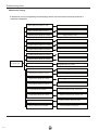
CONTENTS
Safety Cautions ................................................................................................................................1
Operation of wireless remote control .................................................................................................4
Emergency operation ........................................................................................................................9
Product Specifications .....................................................................................................................10
Part name ........................................................................................................................................12
Dimensions ......................................................................................................................................13
Schematic Diagram .........................................................................................................................15
PCB function manual and operation method ...................................................................................2
Appending data ...............................................................................................................................
Refrigerant sysem diagram .............................................................................................................
Installation .......................................................................................................................................
Troubleshooting Guide ....................................................................................................................
Disassembly ....................................................................................................................................
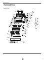
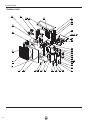
Exploded View .................................................................................................................................
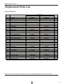
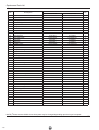
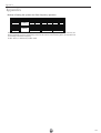
Replacement Parts List ....................................................................................................................
Appendix ..........................................................................................................................................
122
!"#$%&'!($)*+,
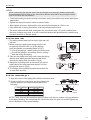
Safety Cautions
To prevent injury to the user or other people and property damage, the following instructions must
be followed.
■ Incorrect operation due to ignoring instruction will cause harm or damage. The seriousness is
classified by the following indications.
This symbol indicates the possibility of death or serious injury.
This symbol indicates the possibility of injury or damage to properties only.
■ Meanings of symbols used in this manual are as shown below.
Be sure not to do.
Be sure to follow the instruction.
ƾ Earth: The ground be connected!
ƾBe sure to pull out the power plug when not
using the air conditioner for a long time.
If not, please ask the qualified personnel to install. Furthermore,
don't connect each wire to the gas pipe, water pipe, drainage
pipe, drainage pipe or any other improper places.
ƾ Select the most appropriate temperature.
Otherwise, the accumulated dust may cause fire or electric
shock.
ƾ Don't leave windows and doors open for a
long time while operating the air conditioner.
Keep room cooer than outside
about 5 degree.
It can preclude the electricity wasted.
It can decrease the air conditioning capacity.
123
!"#$%& !"#$%&'
ƾ For re-installation of the installed product,
always contact a dealer or an authorized
service center.
There is risk of fire, electric shock, explosion, or
injury.
ƾ Be cautious when unpacking and installing
the product.
Sharp edges could cause injury. Be especially careful of the case edges and the fins on the condenser
and evaporator.
ƾ Do not install the product on a defective
installation stand.
ƾ Do not install, remove, or re-install the
unit by yourself.
There is risk of fire, electric shock, explosion, or
injury.
ƾ For installation, always contact the
dealer or an Authorized service center.
There is risk of fire, electric shock, explosion, or injury.
ƾ Be sure the installation area does not
deteriorate with age.
• It may cause injury, accident, or damage to the
product.
• If the base collapses, the air conditioner could fall
with it, causing property damage, product failure,
and personal injury.
124
!"#$%& !"#$%&'
ƾ
Don't place a space heater near the air
conditioner.
ƾ
It can cause afire or explosion.
Or CO toxicosis may occur for imcomplete
burning.
ƾ
The airflow direction can be adjusted
appropriately.At operating, adjust the
vertical airflow direction by adjusting the
louvers of upward/downward direction.
And then, hold two ends of left and right
louver to adjust the horizontal airflow.
Louver of left/right direction
ƾ
ƾDon't insert your hands or stick into the air
intake or outlet vents.
Louver of upward/
downward direction.
Don't apply the cold wind to the body for
a long time.
Keep combustible spray away from
the units more than 1m.
Otherwise it will cause accident.
ƾ Don't blow the wind to animals and plants
directly. It can cause a bad influence to
them.
It can cause the health problems.
ƾ
Splashing water on the air conditioner
can cause an electric shock and
malfunction.
ƾ
Don't use the air conditioner for other purposes, such as drying clothes, preserving
foods, etc.
!
125
!"#$%&'()'*)+&#","--)#".'%")/'(%#',
Operation of wireless remote control
Note: There is no fan display shown on the front
panel of the indoor unit
126
Operation of wireless remote control
This function only operates when unit is
in DRY or Cooling mode and should be
on when used in high humidity indoor
environment to dry indoor coil to prevent
mould growing on the coil.
To set this function press Below button,
an Icon will be displayed on LCD remote
controller. When this function is on and unit
is turned off at the remote controller the
indoor fan will continue to operate for period
of time then will turn off.If you press the
Below button whilst the unit is turned off and
fan is running
127
Operation of wireless remote control
TIMER ON
TIMER ON BUTTON
●
Remote control
SWING UP AND DOWN BUTTON
●
Press this button, to set up swing angle,
which circularly changes as below:
OFF
This is an universal use remote controller. If
remote controller sends the following three
kinds of status that the swing status of main
unit will be:
When the guide louver start to swing up and
down, if turn off the Swing, the air guide louver
will stop at current position.
which indicates the guide louver swings up
and down between that all five positions.
TIMER OFF
●
Timer On setting: Signal ìONî will blink
and display, signal
will conceal, the
numerical section will become the timer
on setting status. During 5 seconds blink,
by pressing + or - button to adjust the
time value of numerical section, every
press of that button, the value will be
increased or decreased 1 minute. Hold
pressing + or -button, 2 seconds later,
it quickly change, the way of change is:
During the initial 2.5 seconds, ten numbers
change in the one place of minute, then
the one place is constant, ten numbers
change in the tens place of minute at 2.5
seconds speed and carry. During 5s blink,
press the Timer button, the timer setting
succeeds. The Timer On has been set up,
repress the timer On button, the Timer
On will be canceled. Before setting the
Timer, please adjust the Clock to the
current actual time.
TIMER OFF BUTTON
Once press this key to enter into
TIMER OFF setup, in which case
the TIMER OFF icon will blink.
The method of setting is the same
as for TIMER ON.
To turn the display panel(indoor
unit) on or off press the light
button on the remote controller.
If the light function is on a
which is be displayed on the LCD
panel of the remote controller
When pressing - and + together the
remote controller will be locked.to
release lock function press - and +
together again.
ć7 Ŗ
When unit isoff, press MODE and button simultaneously to switch
between ć and ̧ 128
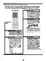
Operation of wireless remote control
Guide for operation- General operation
1. After powered on, press ON/OFF button, the unit will start to run.(Note: When
it is powered off, the guide louver of main unit will close automatically.)
2. Press MODE button, select desired running mode, or press COOL or HEAT
mode to enter into the corresponding operation directly.
3. Pressing +or - button, to set the desired temperature. (It is unnecessary
to set the temp. at AUTO mode.)
4. Pressing FAN button, set fan speed, can select AUTO FAN, LOW, MID
and HIGH.
5. Pressing
button, to select the swing.
Guide for operation- Optional operation
1. Press SLEEP button, to set sleep.
2. Press TIMER ON and TIMER OFF button, can set the scheduled timer on
or timer off.
3. Press LIGHT button, to control the on and off of the displaying part of the
unit (This function may be not available for some units).
4. Press TURBO button, can realize the ON and OFF of TURBO function.
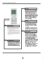
Introduction for special function
ƾ About AUTO RUN
When AUTO RUN mode is selected, the setting temperature will not be displayed on the
LCD, the unit will be in accordance with the room temp. automatically to select the suitable
running method and to make ambient comfortable.
ƾ About turbo function
If start this function, the unit will run at super-high fan speed to cool or heat quickly so that
the ambient temp. approachs the preset temp. as soon as possible.
ƾ About swing up and down
1. Press swing up and down button continuously more than 2s,the main unit will swing back
and forth from up to down, and then loosen the button, the unit will stop swinging and present
position of guide louver will be kept immediately.
2. Under swing up and down mode, when the status is switched from off to , if press this
button again 2s later,
status will switch to off status directly; if press this button again
within 2s,the change of swing status will also depend on the circulation sequence stated above.
129
Operation of wireless remote control
ƾ About new function of defrosting
It indicates: after starting this function by remote controller and the unit has been under
defrost status, If turn off the unit by remote controller, the unit will not stop defrosting until
it is finished; if change setting mode by remote controller, the function ,which is set last
time, won't be carried out until defrosting finished.
Operation of this function on or off: If remote controller is under off status, press mode button
and blow button simultaneously in order to enter or cancel this new function. If the unit is under
defrost mode, dual eight position on remote controller will display H1.If switch to heat mode,
the position will display H1, which flickers for 5s, in which case, press +/- button, H1 will
disappear and setting temp. be displayed.
After remote controller is powered on, the new defrost function will be defaulted to be closed.
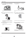
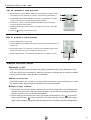
Changing batteries and notices
Slightly to press the place with
1
, along the arrowhead direction to push the back cover of wireless
remote control. (As show in figure)
2Take out the old batteries. (As show in figure)
3 Insert two new AAA1.5V dry batteries, and pay attention to the polarity.
(As show in figure)
4 Attach the back cover of wireless remote control. (As show in figure)
ƾ NOTE:
ƽ When changing the batteries, do not use the old or different batteries,
Fi g.1
otherwise, it can cause the malfunction of the wireless remote control.
ƽ If the wireless remote control will not be used for a long time, please
take them out, and don't let the leakage liquid damage the wireless
remote control.
ƽ The operation should be in its receiving range.
ƽ It should be placed at where is 1m away from the TV set or stereo sound sets.
ƽ If the wireless remote control can not operate normally, please take them out,
after 30s later and reinsert, if they cannot normally run, please change them.
130
Sketch map for
changing batteries
Fig.2
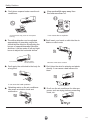
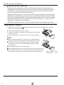
Emergency operation
Displayer indicator light control of indoor unit
It's a special selective buttonfor the users ,who are not accustomed to the
light at sleeping.
ƽ Get
the displayer indicator light on: When setting the light function,the mark will
display on the remote controller screen by
pressing this button. In which case,the dissplayer indicator light will be on if the AC receives
this signal.
ƽ Get
the displayer indicator light off: If cancel the light function,the mark
will disap-
per on the remote controller screen by pressing this
button. In which case, the displayer indicator light will
be off if the AC receives this signal.
Emergency operation
If the wireless remote control is lost
or broken, please use the manual switch
button. At this time, the unit will run at the
Auto mode, but the temperature and fan
speed cannot be changed. The operation
was shown as below:
To open the panel, the manual switch
Manual switch
Fig.3
is on the displayer box.
ƽ
Turn on the unit: At unit turned off, press
the button,the unit will run at Auto mode
immediately.The microcomputer will accord
to the indoor temperature to select (Cooling,
Heating, Fan) and obtain the comfortable effect.
ƽ
Turn off the unit: At unit turned on, press the
button, the unit will stop working.
131
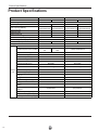
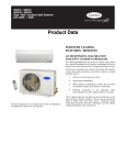
Product Specifications
Product Specifications
Model
EVHC 09 DSAAAR
Function
COOLING
Rated Voltage
Rated Frequency
Total Capacity (W/Btu/h)
Power Input (W)
Rated Input (W)
Rated Current (A)
HEATING
Energy Class
Model of Indoor Unit
Fan Motor Speed (r/min) (H/M/L)
Output of Fan Motor (w)
Input of Heater (w)
HEATING
1400
1450
1600
6.3
7.0
6.1
1650
7.2
500
560
1.6
1.2
2.33/3.4/4.21
2.784/3.69/3.87
2.44/3.3/4.14
3/3.64/3.97
A/A
A/A
EVKC 09 DS
EVKC 12 DS
(1260)/1050/920/ (1320)/1200/1100
730
/950
(1260)/1070/900/730
10
20
None
/
Fan Motor Capacitor (uF)
1.0
1.0
Fan Motor RLA(A)
0.1
0.254
Cross flow fan - 1
Cross flow fan - 1
φ85×596
φ92 X 645
Aluminum fin-copper tube
Aluminum fin-copper tube
Φ7
7
2-1.5
2-1.4
581X264X25.4
645X25.4X267
MP24AA
MP24AA
1.5
PCB 3.15A
2.4
PCB 3.15A
(40)/37/31/23
(41)/37/33/24
(54)/50/46/43
(54)/51/48/45
Fan Type-Piece
Diameter-Length (mm)
Evaporator
Indoor Pipe Diameter (mm)
unit Row-Fin Gap(mm)
Coil length (l)×height (H)×coil
width (L)
Swing Motor Model
132
COOLING
220-240V∼
220-240V∼
80/50/25
80/53/25
95/68/25
95/74/25
3100/2500/1200 3800/2800//1200 3800/3500/1220
4740/4000/1310
10600/9000/4036 13000/9386/4096 12970/12000/4172 14660/13650/4480
1330/735/280
1365/745/310
1560/1060/295
1420/1100/330
Air Flow Volume (m 3/h) (H/M/L)**
Dehumidifying Volume (l/h)
EER / C.O.P (W/W)
EVHC 12 DSAAAR
Output of Swing Motor (W)
Fuse (A)
Sound Pressure Level dB (A)
(H/M/L)
Sound Power Level dB (A)
(H/M/L)***
Dimension (W/H/D) ( mm)
790×265×170
845×275×180
Dimension of Package(W/H/D)(mm)
870×248×355
915×255×355
Net Weight /Gross Weight (kg)
9 / 12
10/13
Product Specifications
Model of Outdoor Unit
Compressor Manufacturer/trademark
Compressor Model
Compressor Type
L.R.A. (A)
Compressor RLA(A)
Compressor Power Input(W)
Overload Protector
Throttling Method
Starting Method
Working Temp Range (ºC)
Condenser
Pipe Diameter (mm)
Rows-Fin Gap(mm)
Coil length(l) x height(H) x coil width(L)
Fan Motor Speed (rpm) (H/M/L)
Output of Fan Motor (W)
Outdoor Fan Motor RLA(A)
Fan Motor Capacitor (uF)
unit
Air Flow Volume of Outdoor Unit
Fan Type-Piece
Fan Diameter (mm)
Defrosting Method
Climate Type
Isolation
Moisture Protection
Permissible Excessive Operating
Pressure for the Discharge Side(MPa)
Permissible Excessive Operating
Pressure for the Suction Side(MPa)
Sound Pressure Level dB (A) (H/M/L)
Sound Power Level dB (A) (H/M/L)
Dimension (W/H/D) (mm)
Dimension of Package (L/W/H)(mm)
Net Weight /Gross Weight (kg)
Refrigerant Charge (kg)
Length (m)
Gas additional charge(g/m)
Connecti Outer
Liquid Pipe (mm)
on Pipe Diameter
Gas Pipe (mm)
Height (m)
Max
Length (m)
Distance
EVJC 09 DS
MITSUBISHI
KNB092FHBMC
single-rotor
25
3.89
895
None
Capillary throttling
Transducer starting
-15 ºC≤ T≤ 43 ºC
Aluminum fin-copper tube
9.52
1-1.6
608X508X22
830±20
30
0.3
2.5
/
Axial fan -1
400
Auto defrost
T1
I
IP24
EVJC 12 DS
MITSUBISHI
KNB092FHBMC
single-rotor
25
8.9
895
222KT-XH-2P-400mm
Capillary throttling
Transducer starting
-10 ºC≤ T≤ 43 ºC
Aluminum fin-copper tube
7
2-1.4
608/498/22
880±20
30
0.3
2
/
Axial fan-1
400
Auto defrost
T1
I
IP24
3.8
3.8
1.2
1.2
53
63
848X260X540
878X360X580
35/40
R410A / 0.8
5
15
Φ6(1/4")
Φ9.52(3/8")
5
15
≤ 54
≤ 64
848X260X540
878X360X580
36/41
R410A / 1.15
5
15
Φ6(1/4")
Φ12(1/2")
5
20
11
133
"#$%&'#()
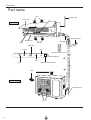
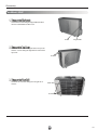
Part name
Air in
Power cable
Front Panel
Indoor unit
Wrapping Tape
Guide louver
Filter
Wall Pipe
Air out
Set Temp
DRY
Cooling
Wireless remote control
LED displayer
Run
Remote control window
Heat
Connection pipe
Air in
Outdoor unit
Drainage hose
Air out
!
134
Dimensions
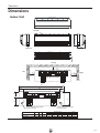
Dimensions
Indoor Unit
W
Air inlet
H
D
Tube exit
Ceiling
Left
Right
Wall-Mounting Plate
W
Q
S
B
H
A
R
x
x
Hole, the position should be confirmed
by client or the erector
Hole, the position should be confirmed
by client or the erector
Model
EVKC 09 DS
EVKC 12 DS
Mounting Plate
B
Q
Hole
X
W(㎜)
H(㎜)
D(㎜)
A
790
845
265
275
170
180
110
140
148
605
32
55
110
147
129
542
169
55
R
S
13
135
Dimensions
Outdoor Unit
D2
D
D1
H
W
W2
W1
Unit:mm
Ov
er
30
Over 60cm
cm
O
O
r
ve
30
ve
0
r6
cm
cm
Bolt
Nut
Wrench
Model
EVJC 09 DS
EVJC 12 DS
136
W(mm)
848
848
W1(mm) W2(mm) H(mm)
762
540
540
762
540
540
D(mm)
320
320
D1(mm) D2(mm)
286
256.6
286
256.6
Schematic Diagram
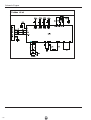
Schematic Diagram
!"!#$%&!'$"'(
Indoor Unit
ক䖯
137
Schematic Diagram
Outdoor Unit
138
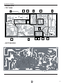
Schematic Diagram
Printed Circuit Board Connector Wiring Diagram
INDOOR UNIT
• TOP VIEW
9
1
10
8
7
2
6
3
5
4
• BOTTOM VIEW
139
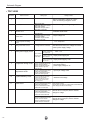
Schematic Diagram
• TOP VIEW
Serial No.
Name of circuit
Testing contents
Before commutating, voltage:
AC current; After commutated, voltage: DC current
1
Commutating filter wave circuit
2
Communication circuit
3
Stabilized voltage supply circuit Chip power supply 5V; relay power supply 12V
4
Buzzer circuit
Buzzer sound
5
Displaying board displaying circuit
Displaying the numerical design correctness
6
Sensor detection temperature circuit
Input IC pin voltage value
7
Jumper cap ciruit
Whether jumper cap is installed or whether it is correctly
installed
8
Fan motor feedback and
driving circuit
Impulse waveform and impulse voltage
9
Crystal oscillatory circuit
Waveform and voltage
10
Reset circuit
Reset pin voltage and waveform
Communication voltage and communication wave shape
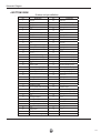
• BOTTOM VIEW
Note: unnoted that the pins are suspending
Indoor unit pin definition
Definition
PIN
Definition
PIN
1
5V power supply Vcc
22
2
AD referrence voltage
23
3
AD referrence ground
24
4
PWM output
25
5
Reset output
26
Retain the swing motor control
Pin1 in advance
Retain the swing motor control
Pin2 in advance
Retain the swing motor control
Pin3 in advance
Retain the swing motor control
Pin4 in advance
Upper and lower swing motor control Pin 1
6
Motor feedback input
27
Upper and lower swing motor control Pin 2
7
Remote control receiving
28
Upper and lower swing motor control Pin 3
8
Buttons input
29
Upper and lower swing motor control Pin 4
9
Buzzer output
30
Cooling/heating selection port
10
Relay control
31
Display board code control G
11
Communication sending
32
Display board code control F
12
Communication receiving
33
Display board code control E
13
Display board code control S1
34
Display board code control D
14
Display board code control S2
35
Display board code control C
15
36
Display board code control B
16
Ground
Display board code control S3
37
Display board code control A
17
Display board code control S4
38
IIC
Bus data port
18
Reset input
39
IIC
Bus clock port
19
Surge signal input
40
Indoor ambient temperature sampling port
20
Surge singal output
41
21
Ground
42
Indoor tube temperature sampling port
Quick test port (retain the temperature
sampling port)
140
Schematic Diagram
Outdoor Unit
• TOP VIEW
2
1
7
3
4
8
5
9
10
6
11
12
• BOTTOM VIEW
!
141
Schematic Diagram
• TOP VIEW
Serial No.
Name of circuit
1
Commutating filter circuit
2
PFC circuit
3
Indicator circuit
4
Fan motor’s four-way valve
control circuit
5
Current of power on testing
circuit
6
Strong current filter cuircuit
7
Switch power supply circuit
8
Compressor driving circuit
9
Sensor detecting
temperature circuit
10
Crystal oscillatory circuit
11
Reset circuit
12
Communication circuit
Testing spot
Testing content
Before commutating voltage AC current;
After commutating voltage DC current
R212 underneath
multimeter black pen contact
with U406 radiator
multimeter red pen contact
with R212 underneath
Bus bar voltage, working voltage 15V
Indicator on/off times
R407right side
multimeter black pen contact
with U404 radiator
multimeter red pen contact
with R407 right side
Output voltage:12V
PTC temperature
Voltage of R101 both sides
The pen of multimeter
red meter contacts with
D304 negative port
The pen of multimeter
The pen of multimeter
black meter contacts
red meter contacts with
with U404 radiator
C405 underneath
The pen of multimeter
red meter contacts with
Pins 7,8 of U4
R201 left side
The pen of multimeter black meter
contacts with U404 radiator
The pen of multimeter red meter
contacts with R201 right side
R407 right side
The pen of multimeter black meter
contacts with U404 radiator
The pen of multimeter red meter
contacts with R407 right side
Both sides of R3
The pen of multimeter black meter
contacts with U404 radiator
The pen of multimeter red meter
to test the upper side and lower
side voltage of R3
C17 underneath
The pen of multimeter black meter
contacts with U404 radiator
The pen of multimeter red meter
contacts with C17 lower side
After filtered the waves, the voltage AC normal
value is power supply voltage
IPM˖15V
Chips power supply:5V
Chips power supply: 3.3V
Bus bar voltage
The normal value is
power supply voltage X1.42
Input IC pin voltage value
Waveform and voltage
Reset voltage and wave
normal value: once power on, instantly there is 200 millisecond
lower voltage, after that is 3.3V all along
C503 underneath
The pen of multimeter black meter
contacts with U404 radiator
The pen of multimeter red meter
contacts with C503 underneath
Communication receiving signal detection
Normal value: in this point, there is inerratic
change for voltage
C524 underneath
The pen of multimeter black meter
contacts with U404 radiator
The pen of multimeter red meter
contacts with C524 underneath
Communication sending singal detection
Normal value: in this point, there is inerratic
change for voltage
142
Schematic Diagram
• BOTTOM VIEW
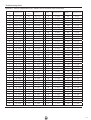
Outdoor unit pin definition
Definition
PIN
Definition
PIN
1
JTAG pin
49
Quick test
2
Memory
50
Overload protection singal input
3
Digital ground
51
25/35 Models selection port
4
+3.3V
53
Digital ground
5
Fan motor PWM output
54
+3.3V
6
Module protection signal input
56
Fan motor speed feedback input
7
Memory
58
Digital ground
8
Phase-locked loop
59
+3.3V
9
Phase-locked loop
60
Electronic expansion valve driving signal
10
+3.3V
61
JTAG Pin
12
Power supply control output
62
JTAG Pin
13
Auxiliary heat control output
63
Digital ground
14
Four-way valve control output
64
+3.3V
16
Zero crossing detection
signal input
67
U phase current sampling input
17
Communication sending
68
W phase current sampling input
18
Communication receiving
69
V phase current sampling input
19
Digital ground
70
Air exhaust sampling input
20
+3.3V
71
Ambient temperature sampling input
22
Indicator output
72
Air intake sampling input
23
PFC Protection signal input
73
Tube temperature sampling input
24
PFC driving level output
74
Current sampling input
26
Indicator output
75
Bus voltage sampling input
27
Electronic expansion valve driving signal
76
Electronic valve temperature
sampling input
28
PWM Signal output
81
Digital ground
29
Digital ground
82
+3.3V
30
+3.3V
83
+3.3V
31
PWM Signal output
84
Digital ground
32
Electronic expansion valve driving signal
86
Indicator output
33
PWM Signal output
87
Crystal oscillatory pin input
34
Digital ground
88
Crystal oscillatory pin input
35
+3.3V
90
Digital ground
36
PWM Signal output
91
+3.3V
37
PWM Signal output
93
Reset signal
38
Electronic expansion valve driving signal
94
JTAG Pin
39
PWM Signal output
96
JTAG Pin
40
+5.0V
97
Digital ground
46
Digital ground
98
+3.3V
47
+3.3V
99
JTAG Pin
48
Fan motor control singal output
100
JTAG Pin
143
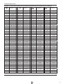
PCB function manual and operation method
PCB function manual and operation method
1. Temperature Parameters
u
Indoor preset temperature (Tpreset)
u
Indoor ambient temperature (Tamb.)
2. Basic Functions
Once energized, in no case should the compressor be restarted within less than 3 minutes. In the situation that memory
function is available, for the first energization, if the compressor is at stop before de-energization, the compressor will be
started without a 3-minute lag; if the compressor is in operation before de-energization, the compressor will be started with
a 3-minute lag; and once started, the compressor will not be stopped within 6 minutes regardless of changes in room
temperature;
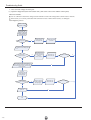
(1) Cooling Mode
ķ Working conditions and process of cooling
When Tamb.ıTpreset, the unit will enter cooling operation, in which case the indoor fan, the outdoor fan and the compressor
will work and the indoor fan will run at preset speed.
When Tamb.İTpreset -2ć, the compressor will stop, the outdoor fan will stop with a time lag of 30s, and the indoor fan will
run at preset speed.
When Tpreset -2ć< Tamb.< Tpreset +1ć, the unit will remain at its previous state.
Ø Under this mode, the four-way valve will be de-energized and temperature can be set within a range from 16 to 30ć.
If the compressor is shut down for some reason, the indoor fan and the swing device will operate at original state.
Tamb
Start cooling
Tpreset
Original working state
Tpreset-2ć
Stop cooling
6 minutes
3 minutes
6 minutes
Compressor
Outdoor fan
Indoor fan
Preset wind speed
Run
Stop
ĸ Protection
u
Antifreeze protection
Under cooling and dehumidifying mode, 6 minutes after the compressor is started:
If T evap.İ2ć, the compressor will operate at reduced frequency.
If T evap.İ-1ć is detected for durative 3 minutes, the compressor will stop, and after 30 seconds, the outdoor fan will stop;
and under cooling mode, the indoor fan and the swing motor will remain at the original state.
If T evap. ı6ć and the compressor has remained at OFF for at least 3 minutes, the compressor will resume its original
operation state.
u
Total current up and frequency down protection
If ItotalİA, frequency rise will be allowed; if ItotalıB, frequency rise will not be allowed; ifItotalıC, the compressor will
run at reduced frequency; and if ItotalıD, the compressor will stop and the outdoor fan will stop with a time lag of 30s.
(2) Dehumidifying Mode
ķ Working conditions and process of dehumidifying
If Tamb.ηTpreset, the unit will enter cooling and dehumidifying mode, in which case the compressor and the outdoor fan will
operate and the indoor fan will run at low speed.
If Tpreset -2ćİTamb.İTpreset, the compressor remains at its original operation state.
If Tamb.< Tpreset -2ć, the compressor will stop, the outdoor fan will stop with a time lag of 30s, and the indoor fan will
operate at low speed.
144
Operation
ĸ Protection
Protection is the same as that under the cooling mode.
(3) Heating Mode
ķ Working conditions and process of heating
If Tamb.≤Tpreset +2ć, the unit enters heating mode, in which case the four-way valve, the compressor and the outdoor fan
will operate simultaneously, and the indoor fan will run at preset speed in the condition of preset cold air prevention.
If T amb.≥Tpreset +5ć, the compressor will stop, the outdoor fan will stop with a time lag of 30s, and the indoor fan will stop
after 60-second blow at low speed
If Tpreset +2ć<T amb.< Tpreset +5ć, the unit will maintain its original operating status.
Ø
Under this mode, the four-way valve is energized and temperature can be set within a range of 16 - 30ć. The
operating symbol, the heating symbol and preset temperature are revealed on the display.
ĸ Condition and process of defrost
When duration of successive heating operation is more than 45 minutes, or accumulated heating time more than 90 minutes,
and one of the following conditions is reached, the unit will enter the defrost mode after 3 minutes.
a.
Toutdoor amb. ≥Ać, Toutdoor tube≤Wć ;
b.
Ać≤Toutdoor amb. <Bć, Toutdoor tube≤Xć ;
c.
Bć≤Toutdoor amb. <Cć, Toutdoor tube≤Yć ;
d.
Touter amb. <Cć, Touter tube≤Zć
At that time, the indoor fan stops and the compressor stops, and after 30 seconds the outer fan will stop, and then after 30
seconds, the four-way valve will stop. After 30 seconds, the compressor is initiated for raising the frequency to defrost
frequency.
When the compressor has operated under defrost mode for 7.5 minutes, or Touter tube ≥Eć, the compressor will be converted
to 53Hz operation. After 30 seconds, the compressor will stop. And after another 30 seconds, the four-way valve will be
opened, and after 60 seconds, the compressor and the outer fan will be started, the indoor fan will run under preset cold air
prevention conditions, and H1 will be displayed at temperature display area on the display panel. Defrost frequency is
70Hz.
3.Protection
u
Cold air prevention
The unit is started under heating mode (the compressor is ON): ķ In the case of T indoor amb. <24ć : if T tube≤40ć and the indoor fan is at stop state, the indoor fan will begin to run at low
speed with a time lag of 2 minutes. Within 2 minutes, if T tubeη40ć, the indoor fan also will run at low speed; and after
1-minute operation at low speed, the indoor fan will be converted to operation at preset speed. Within 1-minute low speed
operation or 2-minute non-operation, if T tubeη42ć, the fan will run at present speed.
ĸ In the case of T indoor amb. ≥24ć: if T tube≤42ć, the indoor fan will run at low speed, and after one minute, the indoor fan
will be converted to preset speed. Within one-minute low speed operation, if T tubeη42ć, the indoor fan will be converted
to preset speed.
1 and ○
2 refers to, under initially heating mode, the indoor ambient temperature before the
Note: T indoor amb. indicated in ○
command to start the compressor is performed according to the program, or after the unit is withdrawn from defrost, the
indoor ambient temperature before the defrost symbol is cleared.
u
Total current up and frequency down protection
If the total current Itotal≤W, frequency rise will be allowed; if Itotal≥X, frequency rise will not be allowed; if Itotal≥Y, the
compressor will run at reduced frequency; and if Itotal≥Z, the compressor will stop and the outdoor fan will stop with a time
lag of 30s.
(4) Fan Mode
Under the mode, the indoor fan will run at preset speed and the compressor, the outdoor fan, the four-way valve and the
electric heater will stop.
Ø
Under the mode, temperature can be set within a range of 16 - 30ć.
(5) AUTO Mode
ķ Working conditions and process of AUTO mode
Under AUTO mode, standard cooling temperature Tpreset is 25ć and standard heating temperature Tpreset is 18ć.
a.
Once energized, if Tamb.≤20ć, the unit will be started under heating mode; if 20ć< Tamb.< 25ć, the unit will run
under fan mode and the run indicator will be bright; and if Tamb.≥25ć, the unit will be started under cooling mode.
145
Operation
a. Under AUTO mode, if Tamb.≥Tpreset is detected, the unit will select to run under cooling mode, in which case implicit
preset temperature is 25ć; if Tamb.≤Tpreset-2ć, the compressor will stop, the outdoor fan will stop with a time lag of 1
minute, and the indoor fan will run at preset speed; and if Tpreset –(-2ć)< Tamb.< Tpreset, the unit will remain at its original
state.
b. Under AUTO mode, if Tamb. ≤Tpreset+2ć is detected, the unit will select to run under heating mode, in which case
implicit preset temperature is 18ć; if Tamb.≥Tpreset+5ć, the compressor will stop, the outdoor fan will stop with a time lag
of 1 minute, and the indoor fan will run under the mode of residue heat blowing; and if Tpreset +2ć< Tamb.< Tpreset+5ć, the
unit will remain at its original state. The cooling-only unit will run under fan mode.
c. Under AUTO mode, if 20ć< Tamb.< 25ć, the unit will remain at its original state.
2.Protection
a. In cooling operation, protection is the same as that under the cooling mode;
b. In heating operation, protection is the same as that under the heating mode;
c. When ambient temperature changes, operation mode will be converted preferentially. Once started, the compressor will
remain unchanged for at least 6 minutes.
(6) Common Protection Functions and Fault Display under COOL, HEAT, DRY and AUTO Modes
ķ Overload protection
T tube: measured temperature of outdoor heat exchanger under cooling mode; and measured temperature of indoor heat
exchanger under heating mode.
1) Cooling overload
a. If T tube≤52ć, the unit will return to its original operation state.
b. If T tube≥55ć, frequency rise is not allowed.
c. If T tube≥58ć, the compressor will run at reduced frequency.
d. If T tube≥62ć, the compressor will stop and the indoor fan will run at preset speed.
2) Heating overload
a. If T tube≤52ć, the unit will return to its original operation state.
b. If T tube≥55ć, frequency rise is not allowed.
c. If T tube≥58ć, the compressor will run at reduced frequency.
d. If T tube≥62ć, the compressor will stop and the indoor fan will blow residue heat and then stop.
ĸ Exhaust temperature protection of compressor
If exhaust temperature ≥98ć, frequency is not allowed to rise.
If exhaust temperature ≥103ć, the compressor will run at reduced frequency.
If exhaust temperature ≥110ć, the compressor will stop.
If exhaust temperature ≤90ć and the compressor has stayed at stop for at least 3 minutes, the compressor will resume its
operation. Ĺ Communication fault
If the unit fails to receive correct signals for durative 3 minutes, communication fault can be justified and the whole system
will stop.
ĺ Module protection
Under module protection mode, the compressor will stop. When the compressor remains at stop for at least 3 minutes, the
compressor will resume its operation. If module protection occurs six times in succession, the compressor will not be started
again.
Ļ Overload protection
If temperature sensed by the overload sensor is over 115ć, the compressor will stop and the outdoor fan will stop with a
time lag of 30 seconds. If temperature is below 95ć, the overload protection will be relieved. ļ If voltage on the DC bus is below 150V or over 420V, the compressor will stop and the outdoor fan will stop with a time
lag of 30 seconds. When voltage on the DC bus returns to its normal value and the compressor has stayed at stop for at least
3 minutes, the compressor will resume its operation.
Ľ Faults of temperature sensors
146
Operation
Designation of sensors
Indoor ambient temperature
Indoor tube temperature
Outdoor ambient temperature
Outdoor tube temperature
Exhaust
Overload
Faults
The sensor is detected to be open-circuited or short-circuited for successive
seconds
The sensor is detected to be open-circuited or short-circuited for successive
seconds
The sensor is detected to be open-circuited or short-circuited for successive
seconds
The sensor is detected to be open-circuited or short-circuited for successive
seconds, and no detection is performed within 10 minutes after defrost begins.
After the compressor has operated for 3 minutes, the sensor is detected to
open-circuited or short-circuited for successive 30 seconds.
After the compressor has operated for 3 minutes, the sensor is detected to
open-circuited or short-circuited for successive 30 seconds.
30
30
30
30
be
be
3. Other Controls
(1) ON/OFF
Press the remote button ON/OFF: the on-off state will be changed once each time you press the button.
(2) Mode Selection:
Press the remote button MODE, then select and show in the following ways: AUTO, COOL, DRY, FAN, HEAT, AUTO.
(3) Temperature Setting Option Button
Each time you press the remote button TEMP+ or TEMP-, the setting temperature will be up or down by 1ć. Regulating
Range: 16~30ć, the button is useless under the AUTO mode.
(4) Time Switch
You should start and stop the machine according to the setting time by remote control.
(5) 5. SLEEP State Control
a. When the air conditioner is under the mode of COOL, DRY, and the SLEEP mode has been set well, after the SLEEP
state keeps about 1 hour, the pre-setting T will raise 1ć, and it will raise 1ć again after 2 hours, so it raise 2ć in 2 hours,
then it will run on at the setting temperature and wind speed.
b. When the air conditioner is under the mode of HEAT, and the Timer has been set well, after the SLEEP state keeps about
1 hour, the pre-setting T will reduce 1ć, and it will reduce 1ć again after 2 hours, so it reduce 2ć in 2 hours, then it will
run on at the setting temperature and wind speed.
c. The setting temperature keeps the same under the FAN mode and AUTO mode.
(6) Indoor Fan Control
The Indoor Fan can be set as HIGH, MED, LOW by remote control, and the Indoor Fan will be respectively run at high,
medium, low speed. It will also be set as AUTO, and the Indoor Fan is as the followings at the automatic wind speed.
Cooling mode: T ring ≥ T setting + 2, high speed; T setting - 2˘T ring˘T setting + 2, medium speed; T ring≤ T setting – 2, low speed.
Sending wind mode: : T ring˚ T setting + 4, high speed; T setting +2≤T ring≤T setting + 4, medium speed; T ring˘ T setting +2, low
speed.
Moisture removal mode: force to be set as the low speed
Heating mode: T ring ≤ T setting + 1 high speed; T setting +1˘T ring˘T setting + 5, medium speed; T ring ≥T setting + 2, low speed.
(7) Buzzer Control
The buzzer will send a “Di” sound when the air conditioner is powered up or received the information sent by the remote
control or there is a button input, the single tube cooler doesn’t receive the remote control ON signal under the mode of
heating mode.
(8) Auto button
If the controller is on, it will stop by pressing the button, and if the controller is off, it will be automatic running state by
pressing the button, swing on and light on, and the main unit will run based on the remote control if there is remote control
order.
(9) Up-and-Down Swinging Control
When power on, the up-and-down motor will firstly move the air deflector to o counter-clockwise, close the air outlet.
After starting the machine, if you don’t set the swinging function, heating mode and auto-heating mode, the up-and-down
air deflector will move to D clockwise; under other modes, the up-and-down air deflector will move to L1. If you set the
swinging function when you start the machine, then the wind blade will swing between L and D. The air deflector has 7
swinging states: Location L, Location A, Location B, Location C, Location D, Location L to Location D, stop at any
location between L-D (the included angle between L~D is the same). The air deflector will be closed at 0 Location, and the
swinging is effectual only on condition that setting the swinging order and the inner fan is running. The indoor fan and
compressor may get the power when air deflector is on the default location.
147
Operation
Heating angle
Cooling angle
(10) Display
ķ Operation pattern and mode pattern display
All the display patterns will display for a time when the power on, the operation indication pattern will display in red under
standby status. When the machine is start by remote control, the indication pattern will light and display the current
operation mode (the mode light includes: Cooling, heating and dehumidify). If you close the light key, all the display
patterns will close.
ĸ Double-8 display
According to the different setting of remote control, the nixie light may display the current temperature (the temperature
scope is from 16 ć to 30 ć) and indoor ambient temperature. The heating and air supply temperature will display 25ć
under auto-mode, the temperature will display 18ć under the heating mode, and the temperature will display H1 under the
defrosting mode.(If you set the fahrenheit temperature display, the nixie light will display according to fahrenheit
temperature)
(11) Protection function and failure display
E2: Freeze-proofing protection E4: Exhausting protection
E5: Overcurrent protection
E6: Communication failure
E8: Overload protection
F1: Indoor ambient sensor start and short circuit (continuously measured failure in 30S)
F2: Indoor evaporator sensor start and short circuit (continuously measured failure in 30S)
F3: Outdoor ambient sensor start and short circuit (continuously measured failure in 30S)
F2: Outdoor condenser sensor start and short circuit (continuously measured failure in 30S, and don’t measure within 10
minutes after defrosted)
F5: Outdoor exhausting sensor start and short circuit (continuously measured failure in 30S after the compressor operated 3
minutes)
H3: Overload protection of compressor
H5: Module protection
PH: High-voltage protection
PL: Low-voltage protection
P1: Nominal cooling and heating
P2: Maximum cooling and heating
P3: Medium cooling and heating
P3: Minimum cooling and heating
(12) Drying Function
You may start or stop the drying function under the modes of cooling and dehumidify at the starting status (The modes of
automatism, heating and air supply do not have drying function). When you start the drying function, after stop the
machine by pressing the switch button, you should keep running the inner fans for 10 minutes under low air damper (The
swing will operate as the former status within 10 minutes, and other load is stopped), then stop the entire machine; When
you stop the drying function, press the switch button will stop the machine directly.
When you start the drying function, operating the drying button will stop the inner fans and close the guide louver.
(13) Memory function when interrupting the power supply
Memory content: mode, swing function, light, set temperature and wind speed.
After interrupted the power supply, the machine will start when recovering the power according to the memory content
automatically. If the last remote control command has not set the timed function, the system will remember the last remote
control command and operate according it. If the last remote control command has set timed function and the power supply
is interrupted before the timed time, the system will remember the timed function of the last remote control command, the
timed time will recounted form power on. If the last remote control command has set timed function, the time is out and the
system is start or stop according to the set time when the power supply is interrupted, the system will remember the
operation status before the power supply was interrupted, and do not carry out timed action; The timed clock will not
remembered.
148
Appending data
Appending data
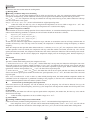
Table showing operation frequency limits for cooling and heating
Outdoor Relative Humidity 37%
Outdoor Relative Humidity 86%
140
130
Indoor Wet Bulb
Temperature( )
120
15
20
110
25
100
80
60
40
Capacity Change Ratio(%)
Capacity Change Ratio(%)
140
130
Indoor Wet Bulb
Temperature( )
120
15
16
110
17
100
80
60
40
20
20
15
35
55
75
95
Compressor Frequency(Hz)
15
35
55
75
95
Compressor Frequency(Hz)
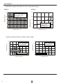
Performance date for both cooling and heating
COOLING:
Temperature
(°C)
Indoor
condition
Outdoor
27/19
35/–
Model
name
Standard
pressure
P (MPa)
Heat exchanger
temp.
pipe
Compresso
Indoor fan Outdoor fan r revolution
mode
(rps)
mode
T1 (°C)
T2 (°C)
09K
0.8 to 1.1
12 to 14
41 to 43
High
High
50
12K
0.8 to 1.0
10 to 12
43 to 45
High
High
69
HEATING:
Temperature
(°C)
Indoor
20/–
condition
Outdoor
7/6
Model
name
Standard
pressure
P (MPa)
Heat exchanger
temp.
pipe
Compresso
Indoor fan Outdoor fan r revolution
mode
(rps)
mode
T1 (°C)
T2 (°C)
09K
2.8 to 3.2
37 to 38
2 to 4
High
High
53
12K
2.8 to 3.2
42 to 44
0 to 3
High
High
74
NOTES :
(1) Measure surface temperature of heat exchanger pipe around center of heat exchanger path
U bent. (Thermistor themometer)
(2) Connecting piping condition : 5 m
!
149
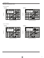
Appending data
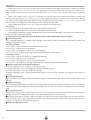
Expanded capacity data tables for both cooling and heating
Cooling
Heating
120
• Conditions
Indoor : DB27˚C/WB19˚C
Indoor air flow : High
Pipe length : 5m
100
100
90
Capacity ratio (%)
Capacity ratio (%)
110
80
70
32 33 34 35 36 37 38 39 40 41 42 43 44 45 46
Outdoor temp. (˚C)
80
• Conditions
Indoor : DB 20˚C
Indoor air flow : High
Pipe length : 5m
60
40
–15
–10
–5
0
10
5
Outdoor temp. (˚C)
Capacity Variation Ratio According to Pipe Length
110
110
• Conditions
Indoor : DB27°C/WB19°C
Outdoor : DB35°C/WB24°C
Indoor air flow: High
100
95
Standard pipe length 5m
90
• Conditions
Indoor : DB27°C/WB19°C
Outdoor : DB35°C/WB24°C
Indoor air flow : High
105
Capacity ratio (%)
Capacity ratio (%)
105
100
95
90
85
85
Maximum pipe length 10m
Maximum Elevation 5m
80
80
0
3
6
9
12
Total pipe length (m)
15
18
0
1
2
3
4
5
6
Total Elevation (m)
!
150
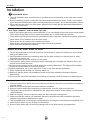
Appending data
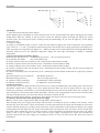
Operation Characteristic Curve
EVHC 09 DSAAAR
Cooling
• Conditions
Indoor : DB27˚C/WB19˚C
Outdoor : DB35˚C/WB24˚C
Indoor air flow : High
Pipe length : 5m
5
• Conditions
Indoor : DB20˚C/WB15˚C
Outdoor : DB7˚C/WB6˚C
Indoor air flow : High
Pipe length : 5m
6
220V
5
Current (A)
6
Current (A)
Heating
4
3
230V
2
220V
4
230V
3
2
240V
240V
1
1
0
10
20
30
40
50
60
70
80
90
0
10
20
Compressor speed (rps)
30
40
50
60
70
80
90
80
90
Compressor speed (rps)
EVHC 12 DSAAAR
Cooling
• Conditions
Indoor : DB27˚C/WB19˚C
Outdoor : DB35˚C/WB24˚C
Indoor air flow : High
Pipe length : 5m
5
• Conditions
Indoor : DB20˚C/WB15˚C
Outdoor : DB7˚C/WB6˚C
Indoor air flow : High
Pipe length : 5m
6
220V
5
Current (A)
6
Current (A)
Heating
4
3
230V
2
220V
4
230V
3
2
240V
240V
1
1
0
10
20
30
40
50
60
Compressor speed (rps)
70
80
90
0
10
20
30
40
50
60
70
Compressor speed (rps)
151
Appending data
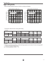
Noise criteria curve tables for both models
Indoor side noise when blowing
Outdoor side noise
1RLVHG%$
Low
Middle
High
Indoor fan motor rotating speed
Compressor frequency/Hz
!
152
!" #$! %&'()*)'!+(,#%$ %+
REFRIGERANT SYSTEM DIAGRAM
3-Way
valve
Heat exchanger
( INDOOR )
Sub-accumulator
Compressor
Muffler
2-Way
valve
4-Way valve
Strainer
Capillary
Strainer
Heat exchanger
( OUTDOOR )
Strainer
Cooling
Heating
!
153
Installation
Installation
Important Notices
1. The unit installation work must be done by qualified personnel according to the local rules and this
manual.
2. Before installating, please contact with local authorized maintenance center, if unit is not installed
by the authorized maintenance center, the malfunction may not solved,due to discommodious contacts.
.
3. When removing the unit to the other
place, please firstly contact with the authorized Maintenance
Center in the local area.
Basic Requirements For Installation Position
Install in the following place may cause malfunction. If it is unavoidable contact with service center please:
●
●
●
●
●
●
Place where strong heat sources, vapors, flammable gas or volatile object are emitted.
Place where high-frequency waves are generated by radio equipment, welders and medical equipment.
Place where a lot of salinities such as coast exists.
Place where the oil (machine oil) is contained in the air.
Place where a sulfured gas such as the hot spring zones is generated.
Other place with special circumstance.
Indoor Unit Installation Position Selection
1. The air inlet and outlet vent should be far from the obstruction, make sure that the air can be blown
through the whole room.
2. Select a position where the condensing water can be easily drained out, and the place is easily
connected for outdoor unit
.
3. Select a location where the children can not reach.
4. Can select the place where is strong enough to withstand the full weight and vibration of the unit.
And will not increase the noise.
Be
sure to leave enough space to allow access for routine maintenance. The height of the installed
5.
location should be 250cm or more from the floor.
6. Select a place about 1m or more away from TVset or any other electric appliances.
7. Select a place where the filter can be easily taken out.
8 . Make sure that the indoor unit installation should accord with installation dimension diagram
requirements.
9 . Do not use the unit in the immediate surroundings of a laundry a bath a shower or a swimming pool.
Outdoor Unit Installation Position Selection
1. Select a location from which noise and outflow air emitted by unit will not inconvenience neighbors,
animals, plants.
2. Select a location where there should be sufficient ventilation.
3. Select a location where there should be no obstructions cover the inlet and outlet vent.
4. The location should be able to withstand the full weight and vibration of the outdoor unit and permit
safe installation.
5. Select a dry place, but do not expose under the direct sunlight or strong wind.
6. Make sure that the outdoor unit installation dimension should accord with installation dimension
diagram, convenient for maintenance, repair.
7. The height difference of connecting the tubing within 5m, the length of connecting the tubing within 10m.
8. Select a place where it is out of reach for the children.
9. Select a place where will not block the passage and do not influence the city appearance.
154
Installation
Safety Requirements For Electric Appliances
1. The power supply should be used the rated voltage and AC exclusive circuit,
the power cable diameter should be satisfied.
2. Don't drag the power cable emphatically.
3. It should be reliably earthed, and it should be connected to the special earth device,
the installation work should be operated by the professional.
The air switch must have the functions of magnetic tripping and heat tripping, in order
to protect the short circuit and overloading.
4. The min. distance from the unit and combustive surface is 1.5m.
5. The appliance shall be installed in accordance with national wiring regulations.
6. An all-pole disconnection switch having a contact separation of at least 3mm in all poles
should be connected in fixed wiring.
Note:
●
Make sure that the Live wire or Zero line as well as the earth wire in the family power
socket can not be wrong connected, there should be reliable and no short circuit in the
diagram.
●
wrong connection may cause fire.
Earthing requirements
1. Air conditioner is type I electric appliance, thus please do conduct reliable earthing
measure.
2. The yellow-green two-color wire in air conditioner is earthing wire and cannot be used
for other propose. It cannot be cut off and be fix it by screw, otherwise it would cause
electric shock.
3. The earth resistance should accord to the National Criterion.
4. The user power must offer the reliable earthing terminal. Please don't connect the
earthing wire with the following place:
ķ Tap water pipe. ĸ Gas pipe.
Ĺ Contamination pipe.
ĺ Other places that professional personnel consider them unreliable.
5. The model and rating values for fuses according the silk print on fuse cover or related
PCB board.
155
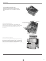
Installation
Install the rear panel
1.Always mount the rear panel horizontally. Due to the water tray of indoor unit has been adopted the
both-way drainage design, the outlet of water tray should be adjusted slightly down when installing, that is
taking the outlet of the water tray as the center of a circle, the included angle between the evaporator and
level should be 0 or more, that is good for condensing water drainage.
Wall
2.Fix the rear panel on the wall with screws. Wall
Mark on the middle of it
Gradienter
Space
Space
(Where is pre-covered with plastic granula)
3.Be sure that the rear panel has been fixed
firmly enough to withstand the weight of an
adult of 60kg, further more, the weight should
be evenly shared by each screw.
to the
wall
above
150mm
to the
wall
above
150mm
55mm
φ 55mm
Left
(Rear piping hole)
Right
(Rear piping hole)
Fig.4
Install the piping hole
Indoor
1.Make the piping hole (Ф55) in the wall at a slight downward slant to the
outdoor side.
Wall pipe
Outdoor
Seal pad
2.Insert the piping-hole sleeve into the hole to prevent the connection piping
and wiring from being damaged when passing through the hole.
Ø55
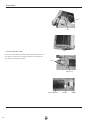
Install the water drainage pipe
1.For well draining, the drain hose should be placed at a downward slant.
Wrenched
Bent
2.Do not wrench or bend the drain hose or flood its end by water.
3.When the long drainage hose passing through indoor,
should wrap the insulation materials.
Flooded
Connect indoor and outdoor electric wires
1.Open the surface panel.
2.Remove the wiring cover .
3.Route the power connection cord and signal control wire (for cooling and heating unit only) from the
back of the indoor unit and pull it toward the front through the wiring hole for connection.
4.Connect the interconnection cord to the terminal block, and then fix the cord with cord anchorge.
5.Reassemble the clampand wiring cover.
6.Recover the surface panel.
yellowgreen
156
brown
Installation
NOTE:
When connecting the electric wire if the wire length is not enough, please contact with
the authorized service shop to buy a exclusive electric wire that is long enough and the
joint on the wire are not allowed.
●
The electric wiring must be correctly connected, wrong connection may cause spare parts
malfunction.
Tighten the terminal screw in order to prevent loose.
After tighten the screw, slight pull the wire and confirm whether is it firm or not.
●
If the earth wire is wrong connection, that may cause electric shock.
●
The cover plate must be fixed, and tighten the connection wire, if it is poor installed, that
the dust, moisture may enter in or the connection terminal will be affected by outside force,
and will cause fire or electric shock.
●
●
Install the indoor unit
The piping can be lead out from right, right rear, left
left rear.
1.When routing the piping and wiring from the left
or right side of indoor unit, cut off the tailings
from the chassis in necessary(Show in Fig.7)
Ł Cut off the tailings 1 when routing the wiring only;
ł Cut off the tailings 1 and tailings 2 when routing
both the wiring and piping.
2. Take out the piping from body case, wrap the piping
electric wire, water pipe with tape and pull them
through the piping hole (As show in Fig.8)
3. Hange the mounting slots of the indoor unit on the
upper tabs of the rear panel and check if it is firm
enough.(As show in Fig.9)
4. The height of the installed location should be 2.5m
or more from the floor.
●
Gas side pipe
External connection
electric wire
Liquid side piping
Tailing 2
Tailing 1
Gas side piping
insulation
Finally wrap it
with tape
Fig.5
Liquid side
Piping insulation
Water drainage pipe
Left
Right
Left rear
Right rear
Fixing hook
Mounting
plate
Fig.6
Mounting
baord
Fig.7
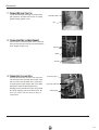
Install the connection pipe
1. Align the center of the piping flare with the relevant valve.
2. Screw in the flare nut by hand and then tighten the
nut with spanner and torque wrench refer to the
following:
Hex nut diameter
Ф6
Ф 9.52
Ф 12
Ф 16
Ф 19
Indoor unit piping
Taper nut Piping
Tightening torque (N·m)
15̚20
31̚35
50̚55
60̚65
70̚75
Spanner
Torque
wrench
NOTE: Firstly connect the connection pipe to indoor unit, then to outdoor unit; pay attention
to the piping bending, do not damage the connection pipe; the joint nut couldn't tighten too
much, otherwise it may cause leakage.
157
Installation
Electric wiring
1. Disassemble the handle on the outdoor unit right side plate.
2.Take off cord anchorage. Connect and fix power connect
cord (for cooling and heating unit,connect and fix power
connect cord and signal control wire)to terminal block.
1 %8
%.
%1 <(*1
3.Fix the power connection cable with cord anchorage,
(for cooling and heating unit, use the cord anchorage
to fix the power connection cable and the signal
control wire).
Handle
4. Ensure wire has been fixed well.
5. Install the handle.
NOTE:
●
●
Wrong wiring may cause spare parts malfunction.
After the cable fixed, make sure there should be
a free space between the connection and
connection and fixing place on the lead wire.
Air purging and leakage test
1. Connect charging hose of manifold valve to charge end of low pressure
valve (both high/low pressure valves must be tightly shut).
2. Connect joint of charging hose to vacuum pump.
Multimeter
-76cmHg
3. Fully open handle handle of Lo manifold valve.
Lo Handle
4. Open the vacuum pump to evacuate. At the beginning, slightly
Charging hose
loosen joint nut of low pressure valve to check if there
is air coming inside. (If noise of vacuum pump has
been changed, the reading of multimeter is 0) Then
tighten the nut.
5. Keep evacuating for more than 15mins and make
sure the reading of multi-meter is -1.0 105pa
(-76cmHg)..
Manifold Valve
Low pressure valve
6. Fully open high/low pressure valves.
7. Remove charging hose from charging end of low pressure valve.
8. Tighten bonnet of low-pressure valve. (As shown in Fig.10)
Manometer
Hi handle
Charging hose
Vacuum pump
Fig.8
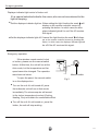
Condensate drainage of outdoor unit (no for cooling only)
The condensate and defrosting water formd during heating
in the outdoor unit can be properly discharged by drainage
pipe .
Installation method:set the drain connection in Ø 25 hole of the
chassis has been installed and then connect drainage pipe
with drain nozzle,so that condensate and defrosting waer can
be properly discharged
Chassis
Drain
connection
!
158
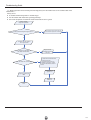
Troubleshooting Guide
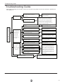
Troubleshooting Guide
Note: When replacing the controller, make sure insert the wire jumper into the new controller, otherwise the
unit display C5
The breaker trips at once when it
Measure insulation resistance to ground to see
if there is any leakage.
is set to "ON".
Trip of breaker or blow
The circuit or the part of the air conditioner has
of fuse
malfunction. They heat and break the insulation
The breaker trips in few minutes
and lead to short circuit or creepage. Measure
when it is set to "ON"
the insulation resistance or eliminate the malfunction one by one. If the breaker itself has
Air conditioner can not start up
malfunction, then replace the breaker.
No power
Check power supply circuit.
Power plug is not well plugged in and poor con-
Check if the plug is properly plugged in and
nection
make the loose contact firm.
The air conditioner
does not react after
it is powered ( after
Change controller fuse
Fuse of controller burnt out
the plug is inserted,
the buzzer does
not sound and the
Fasten the wiring; measure the output
The transformer connection is loose or has bad
voltage of the transformer, if it is
contact or the transformer has malfunction
incorrect, change the transformer
remote startup has
no response)
The remote controller
C o n t ro l l er i s b rok e n
Check remote controller
Remote controller is short of power
Change batteries
Remote controller malfunction
First, press the manual switch button AUTO,
does not receive
signals (after it is
if there is no response,check based on the
powered, the buzzer
will sound, unless it
has
above methods. If it runs normally after
pressing the button,check again whether the
Receiver loose or poor connection
installation position and the connection wire
malfunction)
of the reception head is correct. If it is
correct,then replace the receiver or the re-
Receiver is broken
mote controller.
heck the voltage. If it is lower than 10£¥ of the rated voltage, check the
Power voltage is too low
cause, improve the power supply condition and add the stabilized voltage
power supply.
159
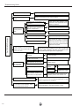
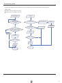
!"#$%&'("")*+,-.#*/&-
Improper set of temperature
Adjust set temperature
If cooling (heating) load is
Check the forecasted load of cooling (heating)
proper
The refrigerant has leakage or is
insufficient
heck and fill the leakage, then
vacuumize it and supplement the refrigerant as required
Leakage between the high presMalfunction of
refrigerant
flow
sure and the low pressure inside the compressor
Malfunction of four-way valve
Local block of capillary
Poor COOL(HEAT) operation
Replace the compressor
Blockage of cooling system
Heat insulation for the connection
pipes of the indoor unit and the outdoor unit is bad.
Replace the four-way valve
Replace the capillary
Judge whether the system is blocked by
observing the condensation of evaporator and the pressure value of the high
pressure manometer and take measures
to deal with the system.
Make sure that heat insulation for the thick and thin pipes
is good. Heat insulation must also be provided for the
joint andthe exposed part of the copper pipe .
Block of outdoor heat ex-
Clean the dust accumulated on the surface of
changer
the heat exchanger.
Air filter were blocked
Clean the filter
To set the fan speed to high or
Fan speed was set too slow
Air circulation
is insufficient
Fan rotation speed becomes
low
Capacitor
Replace the capaci-
damage
tor
Motor damage
Replace the motor
The installation position of the
Good ventilation must be provided for the
outdoor unit is not appropriate.
installation position of the outdoor unit.
The outdoor temperature is too high.
The air tightness is not enough. People
come in and out too frequently. There
are heating devices indoors.
160
middle speed
Properly install the rainproof plate or the sunproof plate. If the
maximum cool air still can not meet the requirement, it is suggested to replace the air conditioner.
Keep certain air tightness indoors, try not to use
electricalappliance with large quantity of heat
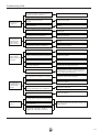
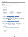
Troubleshooting Guide
The indoor fan motor is burned or breaks or
has the heat protector malfunction.
The fan does not
run when it is set
to supply air.
In the cooling and
heating mode, the
compressor runs,
but the outdoor
fan does not run.
When cooling or
heating, outdoor
fanruns,compressor
doesn't run.
The compressor is
too hot and leads to
the action of the
protector.
Replace the fan motor or the defective part.
The built-in heat protector of the motor breaks
frequently because the motor is
abnormal.
Replace the fan motor
Wrong connection
Make the correction connection based on the circuit
drawing.
The fan capacitor has open circuit or is damaged.
Replace the fan capacitor of the same type and same
specification.
The outdoor fan motor is damaged.
Replace the fan motor
Wrong connection
Make the correct connection based on the circuit
drawing.
The outdoor fan capacitor is damaged.
Replace the fan capacitor
Malfunction of compressor
Replace the compressor
Breakage of running capacitor of compressor
Replace the capacitor
The voltage is too low or too high.
Manostat is recommended.
Wrong wire connection
Connect the circuit diagram correctly
The protector itself has malfunction.
Use the multimeter to check whether the contact of
the compressor is on when it is not overheated. If it
is not on, then replace the protector
The refrigerant is not enough or is too much.
Adjust the volume of the refrigerant
The capillary is blocked and the temperature
rises.
Replace the capillary
The compressor does not run smoothly or is
stuck. The air discharge valve is damaged
Replace the compressor
The protector itself has malfunction.
Replace the protector
The torque of the swing motor is not enough
The swing fan does
not run.
wrong connection
First, check whether the connection is wrong. If no,
replace the parts
The controller is damaged• I•C2003 is
damaged,
the swing relay can not close,
• •
etc
161
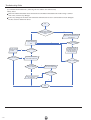
!"#$%&'("")*+,-.#*/&-
Controller malfunction (IC2003 broken,
creepage of
parallel capacitor of relay loop,
Change controller
relay is broken etc.)
In cool, heat mode,the
outdoor
unit and compressor
will not run.
Wire loose or wrong connection
Correctly wire according to the drawing
Improper setting of temperature
Adjust setting temp.
Drainage pipe blocked or broken
Change drainage pipe
Wrap of refrigerant pipe joint is not close
Re-wrap and make it tight.
Water leakage
enough.
Abnormal sound
and shake
162
Fan of indoor unit contacts other parts.
Adjust fan location.
Foreign object in indoor unit
Take out the foreign object.
Compressor shakes too much.
Adjust support washer of compressor, and
tighten loosen screws.
Touch of pipeline of outdoor unit
Separate the touching pipeline.
Touch of inner plates
1. Tighten connect screw.
2. Stick absorbing clay between plates.
Louver of outdoor unit touched outer
case.
Adjust location of louver.
Abnormal sound inside compressor
Change compressor
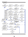
7URXEOHVKRRWLQJ*XLGH
Flashing LED of Indoor/Outdoor Unit and Primary Judgement
Name of running status
1
2
3
4
5
6
7
8
9
10
11
12
13
14
15
16
17
18
19
20
21
22
23
24
25
26
27
Compressor start
Defrosting
Anti-freezing protection
IPM protection
Yellow light
Red light
Green light
Blink once
H1
E2
H5
E5
H4
E4
H3
Blink twice
Blink three times
Blink four times
Overcurrent protection
Blink five times
Overload protection
Blink six times
Air exhaust protection
Blink seven times
Overload protection
Blink eight times
Limited frequency (current)
Blink once
Limited frequency (Air exhaust)
Blink twice
Limited frequency (overload)
Blink three times
Limited frequency (anti-freezing)
Blink four times
Outdoor unit ambient sensor malfunction
Blink five times
Outdoor unit tube temp. sensor malfunction
Blink six times
Outdoor air exhaust sensor malfunction
Blink seven times
Achieve the temperature of unit
startsup
F3
F4
F5
Blink eight times
Communication is normal
Blink continuously
Communication malfunction
OFF
Overload sensor malfunction
Blink nine times
Low voltage protection
Blink twelve times
High voltage protection
Blink thirteen times
Indoor ambient sensor malfunction
Indoor tube temperature sensor
malfunction
Normal cooling or norminal heating
Max. cooling or max. heating
Interim cooling or interim heating
Min. cooling or Min. heating
Indoor unit display
E6
H3
PL
PH
F1
F2
P1
P2
P3
P4
163
!"#$%&'("")*+,-.#*/&Malfunction Display
If malfunction occurs,corresponding code will display and the unit will resume normal until protection or
malfunction disappears.
Yellow indicator blinks for once
Yellow indicator blinks for twice
Yellow indicator blinks for 3 times
Compressor stars (normal)
Defrosting (normal display of indoor unit)
Anti-freezing protection (normal
display of indoor unit)
Yellow indicator blinks for 4 times
IPM protection
Yellow indicator blinks for 5 times
Overcurrent protection
Yellow indicator blinks for 6 times
Overload protection
Yellow indicator blinks for 7 times
Exhaust protection
Yellow indicator blinks for 8 times
Overlod protection of compresoor
Indicator display
of outdoor unit
Red indicator blinks for once
Cooling (dehumidify) or heating current
dropped frequency current.
Red indicator blinks for twice
r
Exhaust
temp.
Red indicator blinksfor 3 times
Tube temp.
Red indicator blinks for 4 times
T tube-in
Red indicator blinks for 5 times
Outdoor condenser temp. sensor mal.
Red indicator for 6 times
dropped frequency temp.
dropped frequency temp.
dropped frequency temp.
Outdoor ambient temp. sensor mal.
Red indicator blinks for 7 times
Outdoor exhaust temp. sensor mal.
Red indicator blinks for 8 times
Starting at temp. does not reach
Green indicator does not blink
Communication is abnormal
!
164
!"#$%&'("")*+,-.#*/&Analysis or processing of some of the malfunction display:
1. Compressor discharge protection
Possible reasons: shortage of refrigerant; blockage of air filter; poor ventilation or air flow short pass for condenser;
the system has noncondensing gas (such as air, water etc.); blockage of capillary assy (including filter); leakage
inside four-way valve causes incorrect operation; malfunction of compressor; malfunction of protection relay;
malfunction of discharge sensor; outdoor temperature too high.
Processing method: refer to the malfunction analysis in the above section.
2.
Low voltage overcurrent protection
3.
Communication malfunction
Possible reason: Sudden drop of supply voltage.
Processing method: Check if communication signal cable is connected reliably.
4. Sensor open or short circuit
Processing method: Check whether sensor is normal, connected with the corresponding position on the
controller and if damage of lead wire is found.
5.
Compressor overload protection
Possible reasons: insufficient or too much refrigerant; blockage of capillary and increase of suction temp.;
improper running of compressor, burning in or stuck of bearing, damage of discharge valve;
malfunction of protector.
Processing method: adjust refrigerant amount; replace the capillary; replace the compressor; use
universal meter to check if the contactor of compressor is fine when it is not overheated, if not replace
the protector.
6.
System malfunction
i.e. overload protection. When tube temperature (Check the temperature of outdoor heat exchanger
when cooling and check the temperature of indoor heat exchanger when heating) is too high,
protection will be activated.
Possible reasons: Outdoor temperature is too high when cooling; insufficient outdoor air circulation;
refrigerant flow malfunction.
please refer to the malfunction analysis in the previous section for handling method .
7. IPM module protection
Processing method:Once the module malfunction happens,if it persists for a long time and can not be self- canceled,
cut off the power and turn off the unit,and then re-energize the unit again after about 10 min.After repeating the
procedure for sever times, if the malfunction still exists,replace the module.
!
165
Troubleshooting Guide
3ǃHow to Check simply the main part
(1) Capacitor charge fault (Fault with outdoor unit) (AP1 below refers to the outdoor control panel)
Main Check Points:
Use AC voltmeter to check if the voltage between terminal L and N on the wiring board is within 210VAC~240VAC.
If the reactor (L) is correctly connected? If the connection is loose or fallen? If the reactor (L) is damaged?
Fault diagnosis process:
Switch on the unit
and wait 1 minute
Use DC voltmeter
to measure the
voltage on the two
ends of electrolytic
capacitor (test3)
Voltage higher than 200V?
Y
Fault with the voltage
testing circuit on
control panel AP1
Replace the control
panel AP1
Switch off the power
and repair the supply
power to restore the
voltage to
210VAC~250VAC
Re-energize and
switch on the unit
N
Measure the AC voltage between
terminal L and N on wiring board
XT
Voltage within
210VAC~250VAC?
N
If the fault is eliminated?
Y
Y
Switch off the power and wait 20 minutes; or
use DC voltmeter to measure the voltage on the
two ends of capacitor (test3), until the voltage
is lower than 20V
N
Check the
connection of reactor
(L in the Electrical
Wiring Diagram)
If the wiring of
reactor L is normal?
N
Connect the reactor L
according to Electrical
Wiring Diagram
Re-energize and
switch on the unit
Y
Replace the control
panel AP1
End
166
N
If the fault is eliminated?
Y
!"#$%&'("")*+,-.#*/&(2) IPM Protection, Out-of-step Fault, Compressor Phase Overcurrent (AP1 below refers
to the outdoor control panel)
Mainly detect:
If the connection between control panel AP1 and compressor COMP is secure? If loose? If the connection is in correct order?
If the voltage input of the machine is within normal range? (Use AC voltmeter to measure the voltage
between terminal L and N on the wiring board XT)
If the compressor coil resistance is normal? If the insulation of compressor coil against the copper tube
is in good condition?
If the working loads of the machine are too high? If the radiation is good?
If the charge volume of refrigerant is correct?
Fault diagnosis process:
167
Troubleshooting Guide
Energize and
switch on
IPM protection
occurs after the
machine has run for
a period of time?
Y
Use AC voltmeter
to measure the
voltage between
terminal L and N
on the wiring
board XT)
If the voltage
between terminal L
and N on wiring
board XT is within
210VAC~250VAC?
N
Check the supply
voltage and
restore it to
210VAC~250VAC
Y
Start and run the
unit. Before
protection occurs,
use DC voltmeter to
measure the voltage
between the two
ends of electrolytic
capacitor on control
panel AP1 (test3)
Voltage between
the two ends of
electrolytic
capacitor (test3) is
higher than 250V
Y
Please confirm:
1. If the indoor and
outdoor heat
exchangers are
dirty? If they are
obstructed by other
objects which affect
the heat exchange
of indoor and
outdoor unit.
2. If the indoor and
outdoor fans are
working normally?
3. If the environment
temperature is too
high, resulting in
that the system
pressure is too high
and exceeds the
permissible range?
4. If the charge
volume of
refrigerant is too
much, resulting in
that the system
pressure is too
high?
5. Other conditions
resulting in that the
system pressure
becomes too high.
The connection
of capacitor C2
is loose.
Stop the unit and
disconnect the power
supply. Wait 20 minutes,
or use DC voltmeter to
measure the voltage
between the two ends of
capacitor C2, until the
voltage is lower than 20V
If capacitor
C2 is failed?
Replace the capacitor
C2. Then, energize
and start the unit.
Y
Replace the
control panel AP1
N
If there is any
abnormality
described above?
Y
Replace the
control panel AP1
Y
Connect the control panel
AP1 and compressor
COMP correctly according
to the Electrical Wiring
Diagram. Then, energize
and start the unit.
If the
resistance is
normal?
N
If the unit can
work
normally?
Replace the
compressor
COMP
Resistance higher
than 500MΩ?
N
Replace the
control panel
AP1
END
168
N
If the unit can
work
normally?
If the unit can
work
normally?
Y
Y
N
Take corrective actions
according to Technical
Service Manual, and
then energize and start
the unit.
N
Use ohmmeter to
measure the resistance
between the two
terminals of compressor
COMP and copper tube.
Y
Reconnect the
capacitor C2 according
to Electrical Wiring
Diagram. Then,
energize and start the
unit.
Y
N
Remove the wires
on the two ends of
capacitor C2. Then,
use
capacitance
meter to measure
the capacitor C2.
Verify as per the
Parameters Sheet.
N
Use ohmmeter to
measure the resistance
between the three
terminals on compressor
COMP, and compare the
measurements with the
compressor resistance on
Service Manual.
If the unit can
work
normally?
N
Stop the unit and
disconnect the power
supply. Then, check
the connection of
capacitor
C2
according to Electrical
Wiring Diagram.
Refer to the
Electrical Wiring
Diagram and check
if the connection
between AP1 and
COMP is loose and if
the connection order
is correct.
If the connection
between AP1 and
COMP is unsecure
or the connection
order is wrong?
N
If the unit can
work
normally?
N
Y
Y
!"#$%&'("")*+,-.#*/&˄3˅High temperature and overload protection diagnosis (AP1 hereinafter refers to the control board of the
outdoor unit)
Mainly detect:
● Is outdoor ambient temperature in normal range?
● Are the outdoor and indoor fans operating normally?
● Is the heat dissipation environment inside and outside the unit is good?
Overheat and high
temperature protection
Y
Is outdoor ambient temperature higher than 53?
Normal protection, please operate it after the
outdoor ambient temperature is normalized.
N
20 minutes after the complete
unit is powered off.
Is heat dissipation of the indoor unit
and outdoor unit abnormal?
Y
Improve the heat
dissipation environment
of the unit
N
Does the outdoor fan work normally?
N
1. Check if the fan terminal OFAN
is connected correctly
2. Resistance between any two
terminals is measure by an ohm
gauge and should be less than 1K
Ohm.
Y
Replace the fan
capacitor C1
Replace the control panel
AP1
Replace the
outdoor fan
End
169
!"#$%&'("")*+,-.#*/&(4) Fail for start up (following AP1 for outdoor unit control board)
Mainly detect:
Whether the compressor wiring is connected correct?
Is time for compressor stopping enough?
Is compressor broken?
Power on the unit
Is stop time of the compressor
longer than 3 minutes?
N
Restart it up after 3 minutes
Y
Does startup fail?
Y
Are the wires for the compressor connected
correctly? Is connection sequence right?
N
Connect the wires as per the
connection diagram
Y
Replace the control panel AP1
N
If the fault is eliminated?
N
Replace the
compressor
Y
End
48
170
Troubleshooting Guide
(5) Out of step diagnosis for the compressor (AP1 hereinafter refers to the control board of the outdoor unit)
Mainly detect:
Whether the unit voltage is too high?
Whether the work voltage is too low?
Out of step occurs once the
unit is powered on.
Out of step occurs in
operation
Is stop time of the
compressor longer than
3 minutes?
Is the outdoor fan working
normally?
Is the outdoor unit blocked
by foreign objects?
Are the wires for the compressor connected
correctly? Is connection sequence right?
Is the connection made in clockwise
direction?
Check if the fan terminal
OFAN is connected correctly
Replace the fan
capacitor C1
Replace the
outdoor fan
Remove foreign objects
Replace the
control panel AP1
Connect the
wires correctly
Replace the control
panel AP1
If the fault is eliminated?
If the fault is eliminated?
Replace the
compressor
Replace the
compressor
End
End
171
Troubleshooting Guide
(6)Overload and air exhaust malfunction detect (following AP1 for outdoor unit control board)
Mainly detect:
Wether the electronic expansion valve is connected well or not? Is electronic expansion valve damaged?
Is refrigerant leaked?
20 minutes after the
complete unit is
powered off
Is the terminal FA for the
electronic expansion valve
connected correctly?
Resistances between the first four pins
close to the terminal hole and the fifth
pin are almost the same, less than 100
ohm.
Replace the electronic
expansion valve
If the fault is eliminated?
Replace the
control panel
AP1
If the fault is eliminated?
Coolant leakage, refilling
the coolant
End
172
Connect the
wires correctly
Troubleshooting Guide
˄7˅Power factor correction (PFC) fault (a fault of outdoor unit) (AP1 hereinafter
refers to the control board of the outdoor unit)
Mainly detect:
Check if the reactor (L) of the outdoor unit and the PFC capacitor are broken
The failure diagnosis process is as follows:
Start
Check wiring of the
reactor (L) of the
outdoor unit and the
PFC capacitor
Whether there is any
damage or
short-circuit?
Y
Replace it as per the
wiring diagram and
reconnect the wires
If the fault is eliminated?
N
Remove the PFC capacitor
and measure resistance
between the two terminals.
N
Is the resistance around zero?
Y
The capacitor is
short circuited and
the capacitor
should be replaced
Restart the unit
If the fault is eliminated?
Y
N
Disconnect the terminals for the
reactor and measure the resistance
between the two terminals of the
reactor by an ohm gauge
Whether there is any damage
or short-circuit?
N
Y
Replace the reactor
Restart the unit
If the fault is eliminated?
Y
N
Replace the control
panel AP1
N
Y
End
173
!"#$%&'("")*+,-.#*/&(8) Communication malfunction: (following AP1 for outdoor unit control board)
Mainly detect:
Detect the indoor and outdoor units connection wire and indoor and outdoor units inside wiring is connect
well or not, if is there any damage?
Is there any damage for the indoor unit mainboard communication circuit? Is communication circuit damaged?
The flow chart for malfunction detect:
Start
Y
N
Did the equipment operate
normally before the failure
occurs?
Check the wiring of the indoor and
outdoor units with reference to the
wiring diagram
Check wiring inside of
the indoor and outdoor
units
Y
Is the connection right?
N
N
The AP1 voltage
detection circuit
is at fault
Y
Correctly connect the
corresponding wires for
the indoor and outdoor
units with reference to
the wiring diagram
Are wires broken?
N
If the fault is eliminated?
N
Check the communication
circuit of the outdoor unit
If the fault is eliminated?
The communication
circuit is abnormal
Y
Replace the main board
˄AP1˅of the outdoor unit
N
If the fault is eliminated?
N
Replace the main board of
the indoor unit
Y
Y
174
End
Y
!"#$%&'("")*+,-.#*/&Appendix 1: form for indoor/outdoor unit's ambient sensor numerical value of resistance
Temp.
˄ć˅
!"
!#
!$
%
Resistance
˄N¡˅
Temp.
˄ć˅
Resistance
˄N¡˅
Temp.
Resistance
˄ć˅
˄N¡˅
Resistance
Temp.
˄ć˅
˄N¡˅
!
175
Troubleshooting Guide
Appendix 2: form for indoor/outdoor unit's tube temperature sensor numerical value of resistance
Temp
˄ć˅
,*
,(
,!
%
176
Resistance
˄N¡˅
!"!#$%%
!&!#$%%
!'(#!%%
!)*#*%%
!$)#%%%
!*&#(%%
!(+#+%%
!(*#%%%
!!'#)%%
Temp
˄ć˅
Resistance
˄N¡˅
Resistance
Resistance
Temp
•
˄ć˅ • • ˄N¡˅
Temp
˄ć˅
• • • • • • • ˄N¡˅
!"#$%&'("")*+,-.#*/&Appendix 3: form for indoor/outdoor unit's air exhaust temperature sensor numerical value of resistance
Temp.
˄ć˅
,+#
,+*
,++
,+%
Resistance
• • • • • • ˄N¡˅
!"#$"%%
&''$!%%
&"%$%%%
&%#$!%%
))%$!%%
)*%$!%%
"!%$)%%
"(!$'%%
"+)$)%%
Temp.
˄ć˅
Resistance
• • • • • • ˄N¡˅
Temp.
Resistance
•
˄ć˅
• • • • ˄N¡˅
Temp.
˄ć˅
•Resistance
• • • • • • ˄N¡˅
($##(
177
!"#""$%&'()
Disassembly
Indoor Unit
Disconnect the unit from power supply before making any checks.
Be sure the power switch is set to “OFF”.
1.Disassemble the front panel
Front panel
Open the front panel, slightly press the both sides of rotating axial
of the panel, to make the rotating axial out of groove, can take down
the front panel.
To push the filter forward, to make the both clasps loosen, can pull
Screw off one screw from the top cover, can take down it.
out off the filter.
Filter
Top cover
2.Disassemble the air guide louver
To make the axis sleeve out of the middle of left air guide louver,
hold both sides of air guide louver, slightly press the middle part
then can disassemble the air guide louver.
Air guide board
Axis sleeve
3.Disassemble the front case
Screw off 7pcs screw from fixing front case, loosen the clasps of
rear side, lift it up, can disassemble the front case.
Screws
Clasps
!
178
Disassembly
4.Disassemble the electric box cover
Slightly press the electric box cover to make the clasps out
take down the ambient sensor, can take down the electrric box
cover.
Electric box cover
Earth screw
Cold plasma
Tube temperature sensor
5.Disassemble electric box
Screw off the screws fix the electrix box, screw off the earh screw,
pull out the tube sensor, pull out the air guide motor, the wiring terminal
of motor, screw off the screws fixing the displayer, can take down
the electric box.
Wire terminal
Screws
Mianboard
6.Disassemble the evaporator
Screw off the screws fixing the connection pipe clamp, loosen the clasp
from left side, take down the connection pipe clamp; Unscrew the screws
Screws
at both sides of evaporator, slightly move right toward, to make the right
side clasp loosen, then can take down the evaporator.
Connection pipe clamp
!
179
Disassembly
Clasp
Screws
Screws
7.Disassemble the motor
Unscrew the screws which fix the motor clamp, take down the motor and
cross flow fan, screw off one screw which connects with the motor and
cross flow fan, then take out the motor.
Screws
Motor clamp
Cross flow fan
Screw
Motor
!
180
!"#""$%&'()
outdoor Unit
Unscrew the screw fixing the big handle,and then
remove it downwards to take it out.
Screw
Big Handle
Unscrew the 2 screws fixing left side of top cover
and the 1 screw fixing the right side to remove the
top cover.
Screws
Unscrew the 4 screws fixing the rear grill to remove it.
Rear Grill
Screws
!
181
Disassembly
Unscrew the 5 screws fixing the panel and
dextrorotate the front panel to pull it out from
groove.
Screws
Unscrew the 2 screws fixing electric box ,and then
unscrew the 5 screws fixing the right side plate to
remove it.
Screws
Right Side Plate
Screws
Electric box cover
Firstly unscrew off two pcs screw on the lelectric box cover,
take down the connection wire of motor, compressor, sensor,
electric heating belt, screw off the earth screw at side wire
terminal and two pcs screw which fixes the electric box, then
can take down the electric box.
Screws
!
182
Disassembly
Loosen the fastening nut fixing the axial flow fan
with a spanner, and then take out the nut, spring
Axial Flow Fan
gasket and flap gasket in turn.
Nut
Unscrew the 4 screws fixing the motor to take out
the motor,and then unscrew the 2 screws fixing the
motor support to take it out.
Screws
Motor
Screws
Four-way valve
Unscrew the fastening nut of the four-way valve
coil and remove the coil. Wrap the four-way valve
with wet cotton and unsolder the 4 weld spots
connecting the four-way valve to take it out. (Note:
Refrigerant should be discharged firstly.)
Welding process should be as quick as possible
and keep wrapping cotton wet all the time. Be
Four-way valve coil
Weld spots
sure not to burn out the lead-out wire of
compressor.
!
183
Disassembly
Respectively unsolder the weld spots of main
capillary and auxiliary capillary to take off the
capillary.
Capillary
Screw off the screws which fix the valves, unsolder the pipeline
take down the valves.
Bolts
Liquid Valve
Gas Valve
Loosen 3 pcs nut from the bottom of compressor, unsolder
the air intake and air exhaust pipeline, becareful to move
the pipeline, and take out the compressor.
Nuts with washers
!
184
Exploded View
Exploded View
Indoor Unit
!
185
Exploded View
Outdoor Unit
!
186
Replacement Parts List
Replacement Parts List
Parts List (Indoor)
No
1
2
3
4
5
6
7
8
9
10
11
12
13
14
15
16
17
18
19
20
21
22
23
24
25
26
27
28
29
30
31
32
33
34
35
36
Description
Wall-Mounting Frame
Rear Case
Evaporator Assy
Evaporator Support
Cross Flow Fan
Bearing cushion rubber base
Ring of Bearing
Volute tongue
Left Axile Bush
Crank
Axile Bush
Swing Louver1
Swing Louver2
Front Case
Filter
Remote Control YB1FA
Decorate Piece
Double-side glue
Receiver Board D5183B
Front Panel
Screw Cover
Guide Louver
Wire Clamp
Rear Clamp
Motor MP24AA
Motor Clamp
Motor FN20J-PG
Electric Box Cover 1
Covering Plate2
Terminal Board T4B3A
Electric Box
Main PCB M809F2J(MI)
Jumping Connector
Transformer 41X26.5G
Power Cable
Connecting Cable
Part Code
EVKC 09 DS
01252015
22202453
0100255203
24212090
10352018
26152022
76512203
26112162
/
10582070
10542008
10512113
10512114
20012120
11122081
30510041
2019223801
/
30565012
20012151S
24252016
10512111
71010103
26112164
1521210801
26112160
15012078
20102848
20122075
42011233
20112064
30138026
4202300106
43110236
400204643
400205236
EVKC 12 DS
01252013
22202454
0100255302
24212091
10352017
26152022
76512203
26112163
10512037
10582070
10542008
10512156
10512155
20012123
1112220401
30510041
2019223601
55112004
30565012
20012153
24252016
10512157
71010003
26112164
1521210801
26112161
150120874
20102848
20122075
42011233
20112064
30138026
4202300105
43110236
400204643
4002052312
Qty
1
1
1
1
1
1
1
1
1
1
1
1
1
1
2
1
1
1
1
1
1
1
1
1
1
1
1
1
1
1
1
1
1
1
1
1
NOTE) *Please ensure GCSC since these parts may be changed depending upon the buyer's request.
65
187
Replacement Parts List
No
Part Code
Description
Qty
1
Front Panel
EVJC 09 DS
01533005
EVJC 12 DS
01533006
2
Clap Board
01233012
01233381
1
1
3
Drainage Connecter
06123401
6123401
1
4
Reactor Support
01203682P
0120368201P
1
5
Temperature Sensor 222KT-XH-2P(white)-4
39000302
39000302
1
6
Compressor KNB092FHBMC
00120228
00120228
1
7
/
/
/
/
8
Compressor Bolt
70210108
70210108
3
9
Nut M6Xφ25X6.5
70310011
70310013
3
10
Valve Support
11
Right Side Plate
12
Valve 3/8
01713041
01713041
1
0130200401
0130200401
1
07100005
07100006
1
13
Valve 1/4
07100003
07100004
1
14
Capillary Assy
0310333305
0310307210
1
15
4-Way Valve
430004022
430004032
1
16
4-way Rever-sing Valve Component
03123042
03123126
1
17
Big Handle
26233433
26233433
1
18
4-way Valve Coil
430004002
430004002
1
19
Wire Clap
71010003
71010003
1
20
Insulation Piece D
70410525
70410525
1
21
Terminal Board A
42011113
42011113
1
22
Electric Box Assy
01403998
01403998
1
23
Electric Box
20113005
20113005
1
24
PCB W8073B
301380021
30138013
1
25
Temperature Sensor
39000208
39000208
1
26
Sensor 20K
390001921
390001921
1
27
Exhaust Gas Temperature Sensor 50K
39000016
39000016
1
28
Electric Box Cover
01413048
01413048
1
29
Sensor Insert
42020063
42020063
1
30
Radiator
49010065
49010065
1
31
Rear Grill
32
Condenser Assy
33
Top Cover Assy
34
Motor Support
01473023
01473023
1
0110359012
0111308203
1
01253261
01253261
1
01705002
01705002
1
35
Reactor L15mH/10A
43130178
43130178
1
36
Reactor Box
01403617
01413504
1
37
Motor FW25K
150130671
15013067
1
38
Axial Flow Fan
10333414
10333413
1
39
Nut
70310131
70310131
1
40
Front Grill
22413431
22413431
1
41
Heating cable
76513004
76513004
1
NOTE) *Please ensure GCSC since these parts may be changed depending upon the buyer's request.
66
188
$SSHQGL[
$SSHQGL[
Method of testing the system at a fixed frequency operation.
9K
Model
Mode
Rotate speed
Cooling
25
Setting temp.
9K
Heating
25
25
9K
50
68
53
80
95
19
P2
74
29
12K
P2
18
P1
25
27
12K
P1
16
P0
Setting temp.
Mode
Rotate speed
12K
P0
80
95
30
After set up the turbo and indoor setting temperature, within 2.5s continuously press “Sleep” button four times, the
displayer will display P0 or the corresponding codes, that will enter into relevant testing status, the compressor will
run according to the relevant frequency.
P0: Min. status; P1: Rated status; P2:Max. status
189