1
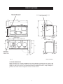
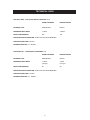
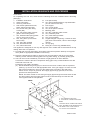
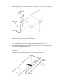
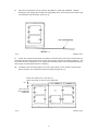
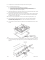
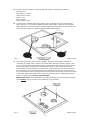
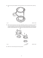
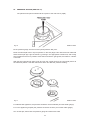
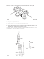
2 BURNER GAS HOB OPTION (FFD)
(For use in 4 Oven Aga Cookers Only)
Installation
Instructions
LEAVE WITH CUSTOMER
THIS PRODUCT IS NOT RETROFITABLE
PLEASE READ THESE INSTRUCTIONS BEFORE INSTALLING THIS APPLIANCE
For use in GB and IE
04/07 EINS 512048
CONTENTS
SECTION
PAGE
GENERAL REQUIREMENTS
3
SPECIFICATIONS
4
TECHNICAL DATA
5
INSTALLATION SEQUENCE & PROCEDURE
6-14
2
GENERAL REQUIREMENTS
IMPORTANT
PLEASE READ THROUGH COMPLETELY BEFORE COMMENCING INSTALLATION.
WARNING: THIS APPLIANCE SHALL BE INSTALLED IN ACCORDANCE WITH THE
REGULATIONS IN FORCE AND ONLY USED IN A WELL VENTILATED SPACE, READ THE
INSTRUCTIONS BEFORE INSTALLING OR USING THIS APPLIANCE.
PRIOR TO INSTALLATION, ENSURE THAT THE LOCAL DISTRIBUTION CONDITIONS (TYPE
OF GAS AND GAS PRESSURE) AND THE ADJUSTMENTS OF THE APPLIANCE ARE
COMPATIBLE.
THE ADJUSTMENT CONDITIONS FOR THIS APPLIANCE ARE STATED ON THE DATA PLATE
, WHICH IS SITUATED INSIDE THE HOB UNIT ON THE METAL BASE.
This appliance is not connected to a combustion products evacuation device. It must be installed
and connected in accordance with current installation regulations. Particular attention shall be
given to the relevant requirements regarding ventilation (B.S. 5440 Part 2). It should be in
accordance also with any relevant requirements of the gas Region and Local Authority.
In your own interests, and that of safety and compliance with the law, all gas appliances must be
installed by a competent person. Failure to install the appliances correctly could lead to
prosecution.
On completion, test the gas installation for tightness.
WARNING: THIS APPLIANCE MUST BE EARTHED.
The appliance is designed for the voltage stated on the data plate.
Any adjacent walls that project above the height of the hob must be of heat resistant material.
Surfaces over the top of the hob must not be closer than 650mm.
THE ISOLATOR SHOULD NOT BE POSITIONED IMMEDIATELY ABOVE THE HOB OR THE
MAIN COOKER, BUT MUST BE SITED WITHIN 1.5 METRES OF THE APPLIANCE.
The hob must be wired and installed by a Qualified Engineer in accordance with the Current
National Wiring Regulations and also any local regulations which may apply.
The appliance requires a 3 amp, 230 volt ~ 50 Hz supply.
The method of connection to the mains supply should ensure complete electrical isolation of the
appliance by the use of a fused double pole switch having a contact separator of at least 3mm
serving only the appliance. The point of connection should be accessible and adjacent to the
appliance. The installation should be protected by a 30 mA Residual Current Circuit Breaker
(RCCB).
IMPORTANT
The wires in the mains lead on this appliance are coloured in accordance with the following:
Green/Yellow - Earth
Blue - Neutral
Brown - Live
3
SPECIFICATIONS
REAR GAS INLET HOLE
POSITION (HOB UNIT)
SIDE ELECTRICAL CONNECTION
HOLE (HOB UNIT)
1487
60
1340
1330
67
830
632
210
851
41
370
3
REAR ENTRY ELECTRICAL CONNECTION
39
51
679
210
756
67
698
1125
591
41
SIDE ENTRY ELECTRICAL
CONNECTION
39
116
Fig. 2
DESN 512066 A
COOKER DIMENSIONS
When surveying for a cooker installation the actual clearance required for the ‘body’ of the
appliance should be increased overall by 10mm beyond the figures quoted. This allows safe
margin to take into account the natural dimensional variations found in major castings. In
particular the width across an appliance recess could be critical.
4
51
TECHNICAL DATA
NATURAL GAS - G20 (APPLIANCE CATEGORY 12H)
FRONT BURNER
REAR BURNER
BURNER TYPE
SEMI-RAPID
RAPID
MAXIMUM HEAT INPUT
1.75kW
3.25kW
INJECTOR MARKING
097
130
PRESSURE POINT POSITION: INJECTOR OF REAR BURNER
PRESSURE SETTING: 20mbar
BURNER IGNITION: H.T. SPARK
PROPANE G31 - (APPLIANCE CATEGORY 13P)
FRONT BURNER
REAR BURNER
BURNER TYPE
SEMI-RAPID
RAPID
MAXIMUM HEAT INPUT
1.75kW
(125g/h)
3.0kW
(214g/h)
INJECTOR MARKING
65
90
PRESSURE POINT POSITION: INJECTOR OF REAR BURNER
PRESSURE SETTING: 37mbar
BURNER IGNITION: H.T. SPARK
5
INSTALLATION SEQUENCE AND PROCEDURE
Loose Items
On unpacking the hob unit, check that the following items are included before discarding
packaging:
1. Installation Instructions
12. Four (M5 screws)
2. Users Instructions
13. Two, flame spreaders/burner cap assemblies
3. Servicing Instructions
(one for each burner size)
4. Hob chassis (fitted with burner,
14. Pan support
bowls, taps and mains lead
15. Two, control knobs
5. Four, burner fixing disc fitting
16. Two, knob spacer washers
screws (M3)
17. Blanking plate
6. Hob, top surface plate (ceramic
18. Two, No. 8 blanking plate screws
glass in frame with gasket)
19. Two, insulation pads
7. Two, stainless steel spring plates
20. Two, heat shield grommets
(one for each burner size)
21. One, top-hat gasket
8. Two, fixing discs (one for each
22. Copper fitting kit comprising: 2 metres of 8mm
burner size)
pipe, 8mm x 8mm elbow, 15mm x 8mm straight
9. Two, fixing disc gaskets
reducer
10. Two, 50mm M3 screws
23. 13 amp plug
11. One, 25mm M3 screw
24. Fitting kit - burner tray (AG4M211601)
This appliance is designed for use only with Aga four oven models and must be fitted in the top
casting above the hot cupboard.
1. Proceed with the main Aga build in accordance with normal practice. Build up to top-plate
level. (Refer to appropriate Installation Instructions).
2. Remove hotcupboard top plate by removing four chrome buttons and the four top plate
retaining screws. Remove warming plate from top plate casting, by carefully prising apart.
3. The hob unit must be installed by connection to rigid pipework of 8mm diameter.
Connection is made to the 8mm compression fitting (gas cock), located inside the rear left
hand side of the hob unit.
Prepare the gas supply as follows:(a) Decide whether the gas supply is to enter from the back or side of the hot cupboard.
(See Fig. 3). Knock out or drill appropriate holes. If the gas supply is to enter from the
side of the hotcupboard, use one of the spark knock-out holes in the side panel.
Pierce centre of top-hat grommet. Run supply pipe through grommet, then insert
grommet into side panel hole.
NOTE: On boiler models do not enter gas supply pipe through the same holes as flow
and return pipes. Also the supply pipe must be routed well away from the flow and
return pipes inside the hotcupboard.
REAR
0
34
65
60
0
14
B
10
0
A
48
17
B
A
A - GAS CONNECTION HOLES
B - ELECTRICAL CONNECTION HOLES
45
46
NOTE:
B
19
95
21
B
0
FOR ELECTRICAL CONNECTION HOLES
ONLY, GROMMETS ARE INSERTED INTO
THE INNER AND OUTER PANELS.
ALL HOLES 19mm DIAMETER
SIDE
Fig. 3
DESN 512063
6
b)
Isolate the gas supply and connect 8mm diameter pipework up to the approximate position
for final connection to the hob unit. (See Fig. 4).
OF D
AR OAR
E
R
B
UP
TC
O
H
REAR ENTRY
GAS PIPE
830
140
SIDE ENTRY
GAS PIPE
Fig. 4
4.
DESN 512062
Prepare the route for the electrical cable as follows:(Refer to wiring diagram Fig. 19 - Page 14).
Decide whether the mains is to enter from the back or side of the hotcupboard. Knock out
or drill appropriate holes and fit grommets (supplied with hob unit). (See Fig. 3).
5.
Place blanking plate AG2M210711 (supplied with hob) on top of the oven so that the return
is to the left and facing upwards. (Fig. 5).
Push return edge up to hotcupboard body and drill through the two holes using a 3.2mm
diameter drill.
Secure the plate with the No.8 self tapping screws provided. (See Fig. 5).
Fig. 5
DESN 511722
7
6.
Non-Electric Agas only - Fit 2 layers of insulation blanket JPAD210722 (supplied with hob)
on top of the oven roof. (See Fig. 6).
Fig. 6
7.
DESN 511733
Electric Aga - Fit one-off insulation blanket JPAD210722 (supplied with hob) on top of oven
roof. (See Fig. 7).
Fig. 7
DESN 511734
8
8.
Place the hotcupboard unit into position alongside the main Aga baseplate, carefully
feeding the gas supply pipe through the appropriate holes, and ensuring that a 16mm gap
is left between the two bases. (See Fig. 8).
Fig. 8
DESN 511254
9.
Check with a spirit level that the front plate is vertical and the ovens level. Check that the
hotcupboard front plate and Aga front are the same height, and that the distance between the
two units has been maintained. If not, adjustment should be made to the hotcupboard position.
Shim under the hotcupboard base if necessary.
10.
Levelling of the simmering plate on the main Aga cooker can be carried out with its top
plate in position and verified across the hotcupboard (See Fig. 9).
FROM TOP SURFACE OF THE AGA TO
LUGS ON FRONT PLATE OF HOTCUPBOARD
64
TOP PLATE OF
HOTCUPBOARD
REMOVED
Fig. 9
DESN 511255
9
11.
Complete the main cooker build and loosely screw down the top plate.
12.
(a)
(b)
(c)
Remove Gas Hob from box.
Disconnect electrical supply cable from hob chassis.
(Unscrew wires from terminal strip and slacken screw in cable clamp).
Feed electrical cable supply in through appropriate grommets in hotcupboard.
(Ensuring cable does not become tangled).
13.
Apply tape (supplied) to the underside of the lap strip in the hotcupboard top plate. Loosely
place hotcupboard top plate into position on hotcupboard.
14.
Place the hob chassis near the cut-out in the top plate casting. Feed the electrical supply
cable in through the cable clamp. Re-connect wires to terminal strip as wiring diagram,
and tighten screw on cable clamp.
14A. Fit 4 push on clips (supplied with hob unit) on to the slots in top plate (See Fig. 10).
15.
Lower the rear face of the chassis into the cut-out in the casting. Slide backwards,
ensuring that the supply pipe lines up with, and makes adequate contact with the
compression fitting on the gas cock.
16.
Fix the chassis in position using the four (M5 size) screws (supplied with hob unit). (See
Fig. 10).
Fig. 10
17.
DESN 513599
Make final gas connection to the gas cock on the hob unit (8mm compression). (See Fig.
11.). After connecting the gas supply turn the gas cock to the ON position, check for gas
tightness.
Fig. 11
DESN 513601
10
18. Connect electrical cable to a fused double pole switch, as described in General
Requirements.
Fuse Rating - 3 amps
Cable Colour Coding
Brown - Live
Blue - Neutral
Green/Yellow - Earth
19. Locate the two stainless steel spring plates on the underside of the hob surface plate
glass. (See Fig. 12). The spring plates should be held loosely in place by the triangular
plates adjacent to each burner hole. Note the spark electrode position of each burner and
rotate the spring plates into approximately the appropriate position.
Fig. 12
DESN 513602
20. Lower the hob surface gently over the chassis. Adjust the spring plates until they fit
accurately over each burner. Secure hob surface plate with three securing screws. (See
Fig. 13). The two 50mm M3 screws should now be fitted through both the clearance hole
in the spring plates, and the hole in the triangular fittings on the underside of the hob
surface plate, and into the M3 nut on the burner mounting bracket. The 25mm M3 screw
fits through the hole in the metal bracket that is visible through the rear control hole into
the nut clipped to the tap mounting bracket. Ensure that the burners are central in the holes
in the glass. Tighten the three screws until the hob surface plate is adequately secure to
ensure a seal all round. DO NOT OVERTIGHTEN.
IMPORTANT NOTE: When assembling hob plate glass ensure that grommets around tap
holes DO NOT foul (push down) micro-switches on tap spindles.
Fig. 13
DESN 513603
11
21. Attach two fixing disc gaskets to the two fixing discs (one for each burner size). (See Fig.
14).
Fig. 14
DESN 512055
22. Attach two fixing discs to the hob using 4 (M3) fitting screws (2 for each burner). (See Fig.
15). You will notice that the burner bowls move upward toward the glass surface as the
screws are tightened. To ensure that the burner bowls are lifted evenly, it is recommended
that the screws be tightened in turn, rotating not more than two turns as a time until tight.
Fig. 15
DESN 513604
23. Attach two control knobs (push onto tap spindle).
12
24.
PRESSURE TESTING (SEE FIG. 16).
The pressure test point is situated at the injector of the rear burner (rapid).
Fig. 16
DESN 513606
Fit the pressure gauge onto the burner injector/pressure test point.
Place the semi-rapid burner cap into position on the hob (align holes with the burner electrode
and thermocouple tip). Light the burner by pushing in the appropriate control knob, and turning
anti-clockwise to the full on position. Press the knob until the gas ignites, then hold for a further
3 seconds.
With the semi-rapid burner alight, push and turn the control knob for the rear (rapid) burner to
the full flame position. Hold the control knob down and take the pressure reading.
Fig. 17
DESN 513605
For Natural Gas appliance, the pressure should be nominal 20mbar (8 inches water gauge).
For L.P.G. appliance (propane) the pressure should be 37mbar (14.8 inches water gauge).
Turn off the taps, disconnect the pressure gauge and refit burner head.
13
Position pan support on to the location pins on top of the burner heads. (See Fig. 18).
Fig. 18
DESN 512067
25. Verify that the top plates are level.
26. Secure handrails as shown on Instruction Sheet EINS 511080.
27. Tighten main Aga top plate, and fix hotcupboard top plate into place using the four tap plate
retaining screws. Finally screw chrome buttons into place.
Commission the main Aga cooker, as stated in the relevant Installation Instructions and carry out
functional tests on each of the features on the hob unit.
Fig. 19
14
15
For further advice or information contact
your local distributor/stockist
With Aga’s policy of continuous product
improvement, the Company reserves the right to
change specifications and make modifications to
the appliance described and illustrated at any time.
Manufactured By
Aga
Station Road
Ketley Telford
Shropshire TF1 5AQ
England
www.aga-web.co.uk
www.agacookshop.co.uk
www.agalinks.com
16