1
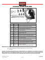
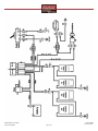
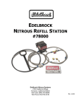
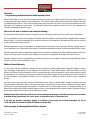
Thank You….
…for purchasing an Edelbrock Nitrous Oxide Injection System.
Nitrous Oxide injection is one of the most exciting performance enhancements for the dollar invested on the market today. With the use
of nitrous oxide come some important safety considerations. This manual has been written to help you during the installation and use of
your Edelbrock Nitrous System. Please read it completely before you install and use your system. Please pay close attention to the safety
information at the beginning of each section. The information contained there specifically pertains to each of the components and
installation methodologies within the section.
Please take the time to read and understand the following….
By installing your Edelbrock Nitrous System, you indicate you have read this document and you agree with the terms stated below.
It is the responsibility of the purchaser to follow all installation instruction guidelines and safety procedures supplied with the Edelbrock
Nitrous Systems. It is also the responsibility of the purchaser to determine the compatibility of the product with the vehicle or the device
on which the purchaser intends to install it.
Edelbrock Corporation assumes no responsibility for damages occurring from misuse, abuse, improper installation, improper operation,
lack of responsible care, or all previously stated reasons resulting from incompatibility with other manufacturers products and/or systems.
Edelbrock Corporation neither recommends nor condones the use of products manufactured or sold by Edelbrock Corporation for use on
vehicles, which may be driven on public roads or highways, and assumes no responsibility for damages incurred by such use.
Edelbrock Corporation assumes no responsibility for damages incurred by the use of products manufactured or sold by Edelbrock Nitrous
Systems on vehicles used for competition or racing.
Edelbrock General Warranty
It is the constant endeavor of Edelbrock Corporation to give our customers the highest quality products obtainable. Edelbrock warrants
each new product, except Performer Series Carburetors, Race Division Parts, Tubular Exhaust Systems, RPM Series Mufflers, Cat-Back
Systems and Performer IAS Shock Absorbers which are warranted separately, to be free from defects in both workmanship and material
for a period of one (1) year from the date of purchase, provided that the product is properly installed, subjected to normal use and service
and that the product is not modified or changed in any way, negligence by customer or installer or used for racing or competition
purposes.
Our warranty service and repair facility is located at 2700 California Street, Torrance, California 90503. Customers who believe they have
a defective product should either return it to the dealer from which it was purchased or ship it directly to Edelbrock along with proof of
purchase and a complete description of the problem. The product must be returned freight pre-paid. If a thorough inspection of the
product by the factory indicates defects in workmanship or material, our sole obligation shall be to repair or replace the product. Warranty
covers only the product itself and not the cost of installation or removal.
Edelbrock Corporation shall not be liable for any and all consequential damages occasioned by the breach of any written
or implied warranty pertaining to this sale in excess of the purchase price of the product sold.
If you have any questions regarding a product or installation, please contact our Technical Department, toll free at
1-800-416-8628 from 7:00am to 5:00pm PST, Monday through Friday.
Thank you again for choosing Edelbrock Nitrous Systems.
©2007 Edelbrock Corporation
Brochure #63-70005
Page 1 of 6
Catalog #70005
Rev. 2/07 - DC/mc
PERFORMER RPM SINGLE TO DUAL-STAGE UPGRADE KIT
CATALOG #70005
INSTALLATION INSTRUCTIONS
1. Disconnect both the nitrous and fuel lines leading from the solenoids to the plate. Be careful not to lose the nitrous and
fuel jet that you currently have installed in the system when removing these lines.
2. Using a 7/16” wrench or socket remove both the nitrous inlet fitting and the fuel inlet fitting.
3. Thoroughly clean the threaded holes of the plate that are exposed after removal of the inlet fittings. Make sure that there
is no metal debris in these holes and that they are free of thread sealant or locking compound. Make sure that no debris
falls into the nitrous or fuel spray bars. After cleaning the area, use a shop vacuum or other vacuum to suction any
remaining debris from the inlet areas.
4. Place a small bead of Teflon Paste, NOT TEFLON TAPE, around the thread of each of the supplied Y-Fittings.
5. Carefully thread the new Y-Fittings into the inlet ports of the plate. Make sure that the blue Y-Fitting gets installed in the
port labeled ‘Nitrous’ and the red Y-Fitting gets installed in the port labeled ‘Fuel’. Using a 7/16” wrench, tighten these
fitting into the plate while being careful not to over-tighten and strip the threads out of the plate. The Teflon Paste should
form a nice bead completely around the port to help ensure a good seal.
6. Place a small bead of Teflon Paste around the threads on the blue 3AN to 1/8”NPT fitting supplied in the kit. Thread this
fitting into the OUTLET port of the supplied Performer Nitrous Solenoid.
7. Place a small bead of Teflon Paste around the threads on the blue 4AN to 1/8”NPT fitting supplied in this kit. Thread this
fitting into the INLET port of the supplied Performer Nitrous Solenoid.
8. Secure the Performer Nitrous Solenoid in a bench vise and tighten both the inlet and outlet fittings being careful not to
over-tighten and strip the threads.
9. Place a small bead of Teflon Paste around the threads on the red 3AN to 1/8”NPT fitting supplied in this kit. Thread this
fitting into the OUTLET port of the supplied Performer Fuel Solenoid.
10. Place a small bead of Teflon Paste around the threads on the red 4AN to 1/8”NPT fitting supplied in this kit. Thread this
fitting into the INLET port of the supplied Performer Fuel Solenoid.
11. Secure the Performer Fuel Solenoid in a bench vise and tighten both the inlet and outlet fittings being careful not to overtighten and strip the threads.
12. Using the supplied solenoid brackets and solenoid mounting screws, mount the solenoids within reach of the jet fittings
on the plate using the supplied 3AN 12” hose for nitrous and 3AN 8” hose for fuel.
13. Choose your intended horsepower settings from the jetting chart on page 3. Find the first stage jetting that you intend to
run in the supplied jet bag that comes with this kit. Use the jets supplied in the jet pack for your Performer RPM Nitrous
System for the second stage jets.
14. Place the first stage nitrous jet in 1 of the inlet ports of the
blue nitrous Y-Fitting of the plate closest to the Performer
Nitrous Solenoid. Install one of the 12” Blue 3AN lines
from the outlet fitting of the Performer Nitrous Solenoid to
the fitting containing the first stage nitrous jet. Snug
down both ends of this line but do not overtighten to
prevent stripping.
15. Place the first stage fuel jet in 1 of the inlet ports of the
red fuel Y-Fitting of the plate closest to the Performer Fuel
Solenoid. Install one of the 8” Red 3AN lines from the
outlet fitting of the Performer Fuel Solenoid to the fitting
containing the first stage fuel jet. Snug down both ends
of this line but do not overtighten to prevent stripping.
©2007 Edelbrock Corporation
Brochure #63-70005
Page 2 of 6
Catalog #70005
Rev. 2/07 - DC/mc
16. Place the second stage nitrous jet in the remaining open inlet fitting of the blue nitrous Y-Fitting. Install the line as
described in step 14 but to the Performer RPM Nitrous Solenoid.
17. Place the second stage fuel jet in the remaining open inlet fitting of the red fuel Y-Fitting. Install the line as described in
step 15 but to the Performer RPM Fuel Solenoid.
18. Using the two red 4AN fuel lines and red 4AN Y-Fitting supplied with this kit, connect each solenoid to the Y-Fitting.
19. Connect the fuel line that was originally connected to your Performer RPM Solenoid to the inlet of the red 4AN Y-Fitting.
20. Repeat steps 18 and 19 using the blue lines for the nitrous solenoids.
21. Wire per the diagram on the following page.
SQUARE-FLANGE JET MAP
Nitrous Jetting
38
46
55
Fuel Jetting
46
53
61
Square-Flange 1st Stage Jet Map
Approx. HP Gain
Timing Adjustment
50hp
2 Degrees Retard
75hp
3 Degrees Retard
100hp
4 Degrees Retard
Footnotes
3
3
3
Nitrous Jetting
71
78
85
99
Fuel Jetting
75
82
89
102
Square-Flange 2nd Stage Jet Map
Approx. HP Gain
Timing Adjustment
150hp
6 Degrees Retard
175hp
7 Degrees Retard
200hp
8 Degrees Retard
250hp
10 Degrees Retard
Footnotes
13
23
245
245
SPREAD-BORE JET MAP
Nitrous Jetting
40
50
59
Fuel Jetting
45
55
65
Spread-Bore 1st Stage Jet Map
Approx. HP Gain
Timing Adjustment
50hp
2 Degrees Retard
75hp
3 Degrees Retard
100hp
4 Degrees Retard
Nitrous Jetting
71
81
Fuel Jetting
75
86
Spread-Bore 2nd Stage Jet Map
Approx. HP Gain
Timing Adjustment
150hp
6 Degrees Retard
175hp
6 Degrees Retard
Footnotes
3
3
3
Footnotes
13
23
Jet Map Footnotes
The jet map above has footnotes that offer the following instructions and technical information.
1 Spark Plugs use Champion RC-12-YC or equivalent.
2 Spark Plugs use Champion C-614-C or equivalent.
3 Fuel use 92 octane pump gasoline or better.
4 Fuel use 110 octane race gasoline or better.
5 Single Plane manifold only. DO NOT use a dual plane manifold at this horsepower level.
©2007 Edelbrock Corporation
Brochure #63-70005
Page 3 of 6
Catalog #70005
Rev. 2/07 - DC/mc
ELECTRICAL SYSTEM INSTALLATION
Item #
Quantity
Description
1
1 ea.
Activation microswitch
2
1 ea.
Activation microswitch bracket (not shown)
3
2 ea.
Activation microswitch mounting nut
4
2 ea.
Activation microswitch mounting screw
5
1 ea.
2 Stage 30 amp relay
6
1 ea.
Wire harness with integral relay/fuse holders
7
1 ea.
Red lighted toggle switch
8
6 ea.
18/22g female spade connector, Nylon insulated
9
2 ea.
14/16g female spade connector, Nylon insulated
10
2 ea.
14-16g male spade connector, Nylon insulated
11
3 ea.
16/18, splice connector
12
5 ea.
14/16g 3/8” ring terminal, Nylon insulated
13
1 ea.
Male blade fuse tap
14
1 ea.
14/16g male spade connector, Nylon insulated
15
1 ea.
Nitrous 2nd stage push button
16
1 ea.
20 amp ATO blade fuse
17
2 ea.
18/22g female spade connector, Nylon insulated
Nomenclature Descriptions:
ATO… the fuse configuration is ATO. When replacing this fuse, ask for an ATO fuse.
“a”… Amperage.
Important: The wiring hardware and instructions included with this kit are intended for 12-volt electrical systems only.
Before attempting to wire your Edelbrock Performer nitrous oxide system, examine and follow the wiring diagram on the
following page. Please call the Edelbrock Technical department with any questions concerning electrical wiring.
©2007 Edelbrock Corporation
Brochure #63-70005
Page 4 of 6
Catalog #70005
Rev. 2/07 - DC/mc
RELAY
RELAY
©2007 Edelbrock Corporation
Brochure #63-70005
Page 5 of 6
Catalog #70005
Rev. 2/07 - DC/mc
NITROUS ELECTRICAL SYSTEM INSTALLATION PROCEDURES
Determine the location of the relay and fuse holder wire harness. Most common installations locate these components inside the driver’s
compartment and close to the fuse panel under the dash. You can also mount the relay and fuse holder harness close to the battery.
However, these connectors are water-resistant not waterproof, so care is required when mounting this assembly under the hood of your
vehicle.
WIRE SCHEMATIC ORIGIN AND DESTINATION MAP
Wire Color
Red
Origin
Relay Harness
Destination
Bat. Volt. Signal
Terminal Used
Ring
Blue
Yellow
Green
Black
White
White
Red
System
Main System Bat.
Voltage Arming Switch
2nd Stage Functions
1st Stage Functions
2nd Stage Functions
1st Stage Functions
Main System Arming
Main System Arming
Main System Arming
Relay Harness
Relay Harness
Relay Harness
Relay Harness
Relay Harness
Relay Harness
Arming Switch
2nd Stage Solenoids
1st Stage Solenoids
2nd Stage Pushbutton
Microswitch
Toggle Switch
White Sys. Arm Wire
Switched 12V Power
Black
Black
Black
Black
Black
Black
Black
Main System Arming
1st Stage Functions
1st Stage Functions
1st Stage Functions
2nd Stage Functions
1st Stage Functions
2nd Stage Functions
Arming Switch
Microswitch
Microswitch Splice
1st Stage Solenoids
2nd Stage Solenoids
1st Stage Solenoids
2nd Stage Solenoids
Ground
Ground
Pushbutton
Yellow Wire
Blue Wire
Ground
Ground
M/F Spades
M/F Spades
Female Spade
Female Spade
Female Spade
Splice Connector
2 F Spades,
Blade Conn.
F Spade, Ring
F Spade, Ring
Splice, F Spade
Male Spade
Male Spade
Ring Terminal
Ring Terminal
The wire harness attached to the relay and fuse holder includes 8 feet of color-coded wires to make the electrical system installation for
your Edelbrock Nitrous System as easy as possible. We recommend not cutting any lengths of wires from the wire harness or complete
the wiring of the nitrous system until all of the mechanical components are securely mounted in their permanent locations.
Once all of the solenoids and switches are placed, route the un-cut wires from the harness to each location allowing enough wire length
on each circuit to not interfere with operating linkages, heat sources, brackets, etc. Pay particular attention to sharp edges along the
route of your wire harness to prevent wire damage.
After you have accounted for the routing of your wires, follow the Wire Harness Schematic on page 15 and use the Origin and Destination
Map as a guide for which electrical connectors are used in each circuit.
Once you have decided the location of the relay and fuse holder, secure them with fasteners (not included with kit) such as sheet metal
screws, bolts and nuts, etc. Allow for some slack in the red wire that connects the relay and fuse holders together.
When mounting your relay and fuse holder, make sure the mounting surface is strong enough to support servicing the relay and fuse.
Also, ensure you allow for some slack in the wire that joins the fuse holder to the relay mount. This will avoid any potential loss of power
due to stress on the wire harness.
The fuse is covered by the fuse mount housing. The relay for the Performer system is rated for 30 amps, and the fuse is 15 amps.
©2007 Edelbrock Corporation
Brochure #63-70005
Page 6 of 6
Catalog #70005
Rev. 2/07 - DC/mc