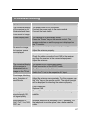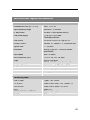
1
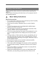
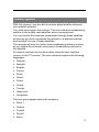
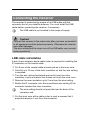
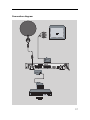
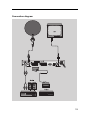
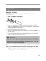
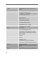
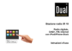
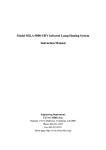
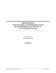
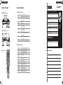
OK
MENU
VOL +
7
VOL –
8
CH +
9
CH –
10
POWER
Rear side of the receiver
Remote control
1
2
3
4
5
6
7
8
9
10
11
12
13
RF OUT
LNB IN
VCR
TV
100 – 240 V~
50/60 Hz, 30 W
0/1
S-VHS
COAXIAL
OPTICAL
RS 232
VIDEO
AUDIO L
AUDIO R
LNB connection for a second satellite receiver
LNB connection for the antenna cable
SCART connection for the video set
SCART connection for the TV set
Mains connection
Firstname
Mains switch
S-Video connection
Digital coaxial audio output
Digital optical audio output
Serial port
Analog video connection
Left analog audio connection
Right analog audio connection
mo
n th s
•
tee
••
ran
Gua
f ro
m p u rc h a s
e
Street
Postcode and city
Telefon no. with areacode
Model / Type: SL 65
Signature of buyer
Faulty-Description:
#
4
5
6
Shows channel location or ttime
Infrared sensor for the signal of the remote control
LED is illuminated if the receiver is switched on or in
standby mode
Confirm
Invokes main menu
Increases volume
Cursor moves to the right
Decreases volume
Cursor moves to the left
Switches to the next higher channel location
Cursor moves up
Switches to the next lower channel location
Cursor moves down
Switches on and switches to the standby mode
Surname
••
Rear side of the receiver
LED display
–
LED POWER
please use block-writing in boxes with CAPITAL LETTERS
•
1
2
3
Sender
a te
Front side of the receiver
-d
Front side of the receiver
GUARANTEE
•• 3
6
Overview of Equipment
PLEASE CUT THIS CARD AND ENCLOSE IT TO THE RETURNING GOOD
Overview of Equipment
Please pay attention
to the attached
service addresses.
Remote control
1
2
3
4
5
6
7
8
9
10
POWER
ZOOM
LIST
TIMER
TEXT
MUTE
M/P
V+
OK
CH q
11
12
13
14
15
16
17
18
19
FAV
RECALL
PAUSE
INFO
0–9
P–
P+
V–
CH p
20
21
22
23
24
25
MENU
EXIT
AUDIO
EPG
TV/SAT
TV/RADIO
Switches on and switches to the standby mode
Enhances the TV image
Shows favourits list (groups)
Timer
Teletext
Turns off sound
Without function
Increases volume/cursor moves to the right
Confirms menu or menu item
Switches to the next lower channel location /
cursor moves down
Invokes favourits list
Switches to previously selected channel
Stills the frame
Displays reception data of the current channel
Selects channel directly, numerical input
Scrolls pages down in menus
Scrolls pages up in menus
Decreases volume/cursor moves to the left
Switches to the next higher channel location /
cursor moves up
Invokes main menu
Exits menu or menu item
Changes audio mode
Electronic Program Guide (if offered)
Switches between terrestrial and satellite antenna
Switches between TV and radio mode
-3-
COMAG_BDA_SL65_S3_GB.indd Abs3:3
12.05.2005 17:47:17 Uhr
Digital Satellite Receiver SL 65
Operating Manual
Version 1, as of 03.05.2005
Preface
This operating manual will help you in the
• appropriate,
• safe and
• favorable
usage of the digital satellite receiver, in short, the ”receiver”.
We assume that the user of the receiver has overall knowledge
regarding the handling of audio and video equipment.
Each person who
• installs,
• connects,
• operates,
• cleans or
• disposes of
this receiver must be familiar with the entire content of this operating
manual. Always keep this operating manual in the proximity of the
receiver.
Style Features
Specific style features have been given in different sections of the
operating manual. Thus, you can easily differentiate whether it
concerns
normal text,
• enumerations or
actions.
.
Contents
Preface ............................................................................................... 2
Style Features ................................................................................... 2
Contents ............................................................................................ 3
Safety Instructions ........................................................................... 5
Basic Safety Instructions .................................................................... 5
Explanation of Safety Instructions ...................................................... 7
Appropriate Usage.............................................................................. 7
Scope of Supply................................................................................ 8
Description ........................................................................................ 9
Connecting the Receiver................................................................ 12
LNB cable installation ....................................................................... 12
Connection with the SCART cable ................................................... 14
Connection with the YUV cable ........................................................ 16
Connection with the S-Video Cable (S-VHS) ................................... 18
Connection with the Cinch cable ...................................................... 20
Connection of an Audio-Digital Receiver.......................................... 22
Operation ......................................................................................... 25
Remote control ................................................................................. 25
Receiver............................................................................................ 26
Operation ......................................................................................... 27
User interface on the TV monitor...................................................... 27
Screen-Inlays while Switching a Channel......................................... 28
Menu Structure ................................................................................. 29
Menu Navigation............................................................................... 30
Edit channel list................................................................................. 32
Favorites list, channel groups ........................................................... 33
Sort channels .................................................................................... 34
Invoke the installation assistant........................................................ 34
Edit or delete the transponder list..................................................... 34
Start scan of broadcasting stations .................................................. 35
Add a new, not pre-programmed satellite and run a scan on it........ 36
Change system setup ....................................................................... 37
PIN code / child lock ......................................................................... 39
3
DiSEqC motor setting ....................................................................... 40
Boot channel..................................................................................... 40
Company Setting .............................................................................. 40
Acoustic signal for the orientation of the satellite antenna ............... 40
Software upgrade via satellite .......................................................... 41
Games .............................................................................................. 41
Keys with special functions .......................................................... 42
EPG mode ........................................................................................ 42
Timer................................................................................................. 43
Audio................................................................................................. 44
Zoom................................................................................................. 44
List .................................................................................................... 44
Switching between TV and SAT ....................................................... 44
TV/Radio ........................................................................................... 45
Teletext ............................................................................................. 45
Fav .................................................................................................... 46
Uninstalling the receiver ................................................................ 46
Cleaning........................................................................................... 46
Troubleshooting ............................................................................. 47
Disposal ........................................................................................... 48
Technical Specifications................................................................ 49
Manufacturer ................................................................................... 50
Guarantee ........................................................................................ 50
Declaration of Conformity.............................................................. 51
Glossary .......................................................................................... 52
4
Safety Instructions
Please read the safety instructions carefully before operating the
receiver.
Please follow all warnings and instructions on the equipment and in
the operating manual.
Basic Safety Instructions
Electrical connection
• Do not expose the receiver to rain as well as any kind of humidity
to avoid risk of fire and electric shock.
• Never open the casing. Otherwise, there is a risk of electric
shock.
• Connect the receiver only to a professionally installed mains
socket of 100–240 V, 50–60 Hz.
• The total power consumption by the antenna connection of the
receiver “LNB IN” must not exceed 350 mA.
• Pull out the mains plug from the socket if the equipment is not in
use for a longer period of time. Always pull out only the mains
plug.
• If foreign bodies or fluids enter the receiver, immediately pull out
the mains plug from the socket. Ask a qualified person to check
the equipment before operating it once again. Otherwise, there is
a risk of electric shock.
• Ensure that the power source (socket) is easily accessible.
• Do not bend or crimp the mains cable.
• If the mains cable is damaged, the receiver must be repaired by
an expert before reusing it. Otherwise, there is a risk of electric
shock.
• Never allow children to operate the receiver or to play with the
antenna unit unless supervised.
• Always ask qualified personnel to carry out maintenance jobs.
Otherwise, you are putting yourself as well as others at risk.
5
• Disconnect the receiver from the power source in case of
operational disruptions.
Suitable location
• Place the receiver on a stable and even base.
• Avoid proximity to:
- heat sources, like e. g. heaters,
- naked flames, like e. g. candles,
- devices with strong magnetic fields, like e. g. loudspeakers.
Never place receptacles filled with liquid (e. g. vases) on the
receiver
• Avoid direct sunlight and places with an extremely high amount of
dust.
• Never cover ventilation slits. Ensure adequate ventilation by
maintaining a safety distance of 5 cm to other objects.
• Do not place any heavy objects on the receiver.
• Humidity may settle in the receiver if is brought into hot
surroundings from a cold one. In this case, wait for about an hour
before operating the equipment.
• Arrange the mains and antenna cable in such a manner that no
one steps or trips over them.
Correct battery handling
• Batteries may contain toxic agents. Ensure that batteries are not
within the reach of children. Children may eat and swallow
batteries.
• Batteries that are getting discharged may damage the remote
control. If you will not use the receiver for a longer period of time,
remove the batteries from the remote control.
• Batteries may contain toxic agents that are hazardous to the
environment. Therefore, dispose of the batteries immediately
according to the prevailing statutory regulations. Never throw the
batteries in normal household waste.
6
Explanation of Safety Instructions
The following categories of safety instructions are included in the
operating manual:
Danger!
Instructions with the word DANGER give a warning against
possible personal injuries.
Caution!
Instructions with the word CAUTION give a warning against
possible material or environmental damages.
These instructions contain special information for
commercial usage of the receiver.
Appropriate Usage
The digital satellite receiver SL 65 receives digital channels in a
covered area. It is exclusively meant for this purpose and should only
be used for the same. This also includes paying attention to all
information in this operating manual especially that of safety
instructions.
Any other usage is considered to be improper and may lead to
material damages and even personal injuries.
The manufacturer does not bear any liability for damages caused
due to improper usage.
7
Scope of Supply
Check the scope of supply after purchase. The scope of supply may
vary according to the type of the receiver. Please follow the
information on the packaging.
8
No.
Pieces
Description
1
1
Digital Satellite Receiver SL -65
2
1
Remote control
3
1
2 batteries type LR 03/AAA/1,5 V
4
1
SCART cable
Description
With this receiver, you are able to receive digital satellite channels
via a satellite antenna.
You need not program the receiver. The most common broadcasting
stations of the mostly used satellites are pre-programmed.
You can receive the channels broadcasted through these satellites
as soon as you have connected the receiver to a satellite antenna
and oriented it to one of these satellites.
The receiver will scan for further new broadcasting stations as soon
as you initiate the automatic scanning of broadcasting stations for
this satellite.
All receiver settings can be done easily using the user interface
(menu) on the TV-monitor. The user interface supports the following
languages:
• German,
• Spanish,
• English,
• French,
• Dutch,
• Greek,
• Polish.
• Czech,
• Turkish.
• Italian and
• Hungarian.
They are pre-programmed by the company:
• Astra 1
• Hotbird
• Turksat
• Sirius2
• Amos
9
The receiver gets a firmware update program through the Astra 19°
satellite.
Other features of the equipment:
• OSD languages: German, English, French, Turkish, Polish,
Greek, Hungarian, Spanish, Czech, Italian, and Dutch
• Software update via satellite Astra 19° or RS232 connection
• Short switching time, fast boot process when switching on the
receiver
• Saves the last channel watched, skip key to the channel
previously watched
• Fully compatible with MPEG-2 and DVB
• MPEG Video (MP@ML), MPEG-1 Audio Layer1, Layer 2
• LNB control logic (sound 0/22 kHz), max. current delivery for LNB
350 mA
• Symbol rate 1-35 MS/s and 950–2150 MHz input frequency
• Manual PID entry possible
• 7 keys at the frontage
• plug and play
• Power draw in standby mode less than 3 W
• 100–240 V, 50/60 Hz mains connection
• Installation assistant
• 4000 channel storage locations
• Child lock
• 1 favorites list and 9 channel groups, editor
• Automatic scanning of broadcasting stations
• List editor for broadcasting stations
• Analogue sound output through Cinch-connector, volume
adjustment possible via remote control
• RCA video output Cinch, S-VHS output
• SPDiF: Coaxial OPTICAL audio connection
• 2 SCART connections for TV and video set
• TV SCART with CVBS, RGB and YUV signal
10
• Loop-through function for the connection of an analogue receiver,
(F connection, loop through)
• Super Fast Videotext with a memory of 800 pages
• Radio reception, background image for radio
• Channel information on the screen, current time
• DiSEqC 1.0, 1.2, Goto X is supported if an appropriate antenna
unit is connected
• SWAP function
• Screen aspect ratios can be set to 4:3, 16:9, and automatically
• Multi-functional timer, 8 x and linked with EPG, sleep timer
• Electronic program guide (EPG)
• SCPC/MCPC reception standard C/Ku-Band satellites
• Automatic selection of NTSC/PAL and video converter
• Signalmeter for the orientation of the paraboloidal-type reflector
Additionally, a suitable channel editor can be downloaded
from our website (www.comag-ag.de). Then you will be
able to edit the channel lists of the receiver using your
computer. Please read the information on our website for
this purpose.
11
Connecting the Receiver
The receiver is connected by means of an LNB cable with the
connector box of your satellite antenna. You must install the LNB
cable before connecting the receiver, if necessary.
The LNB cable is not included in the scope of supply.
Caution!
Connect the receiver to the mains only after you have connected it
to all equipment and the antenna properly. Otherwise the receiver
can suffer damages.
The wire netting and the inner core of the LNB cable carry current
during operations.
LNB cable installation
A pair of wire strippers and a cable cutter is required for installing the
IF-connector on the coaxial cable.
Cut 8 mm of the coaxial cable at each end up to the inner core.
Carefully cut 10 mm of the outer insulation so that the wire netting
is exposed.
Turn the wire netting backwards and wind it over the outer
insulation in such a manner that it does not touch the inner core.
Remove the inner insulation up to 2 mm from the wire netting.
Rotate the IF-connector onto the turned-back wire netting till the
connector touches the inner insulation.
The wire netting should not protrude from the back of the
connector end.
Cut the inner core with a cable cutter in such a manner that it
projects maximum 1 mm from the connector.
12
Installation diagram
13
Connection with the SCART cable
Fasten the IF-connector of the LNB cable onto the “LNB IN“
antenna connection on the receiver.
Insert the SCART cable in the SCART socket “TV” on the
receiver.
Connect the SCART cable to the TV set. Follow the operating
manual of the TV set.
Insert the SCART cable in the SCART socket “VCR” on the
receiver if you want to connect a video set.
Connect the SCART cable to the video set. Follow the operating
manual of the video set.
Insert the Cinch-connector of the Cinch cable in the “AUDIO-R”
and “AUDIO-L” sockets of the receiver if you want to connect a
stereo system.
14
Connection diagram
15
Connection with the YUV cable
If you own a TV set with YUV connections, you can connect it via the
SCART socket “TV“ to the receiver. For this purpose, you need a
YUV cable with YUV connectors at one and a SCART connector at
the other extreme.
Connect the YUV cable (not included in the scope of supply) to
the YUV connectors of the TV set.
Connect the SCART connector of the YUV cable to the SCART
socket “TV“ on the receiver.
Follow the indications in the operating manual of the TV
set.
connect the SCART cable to the SCART socket “VCR” on the
receiver if you want to connect a video set.
Follow the indications in the operating manual of the video
recorder.
This YUV output is a special high quality output and
particularly suitable for flat screens, plasma TV sets or
video projectors (beamers). Please follow the indications in
the operating manual of the connected devices.
16
Connection diagram
17
Connection with the S-Video Cable (S-VHS)
Caution!
Strictly follow instructions for connecting the S-video cable
(SVHS) given in the operating manual of your TV set.
The S-Video cable is not included in the scope of supply.
Insert the S-Video cable in the “S-Video“ socket on the receiver.
Connect the S-Video cable to the TV set.
Insert the Cinch connector of the Cinch cable in the “AUDIO-R“
and “AUDIO-L“ sockets of the receiver.
Connect the Cinch cable to the TV set.
Insert the SCART cable in the SCART socket “VCR” on the
receiver if you want to connect a video set.
Connect the SCART cable to the video set.
Follow the operating manual of the video set.
18
Connection diagram
19
Connection with the Cinch cable
If you own a TV set not provided with a SCART socket, you can
connect the receiver via a Cinch cable.
Connect the “VIDEO“ socket on the receiver to the video input of
the TV set.
Connect the “AUDIO-R“ and “AUDIO-L“ sockets of the receiver to
the audio inputs of the TV set.
20
Connection diagram
21
Connection of an Audio-Digital Receiver
If you want to use 5-channel audio transmission (Dolby digital
sound/AC3), you must connect your audio-digital receiver to the
optical or coaxial output of the receiver.
Caution!
Never connect the Phono input of your stereo system to the
receiver; it may damage your stereo system.
Strictly follow instructions for connecting the Cinch cable given in
the operating manual of your stereo system.
Caution!
Please follow strictly the information regarding the connection in
the operating manual of your audio-digital receiver.
The optical and coaxial cables are not included in the
scope of supply.
Your TV set need not be switched on for radio reception.
You must switch on the TV set if you want to receive TV
sound through your stereo system.
22
Connection of the coaxial digital output
Insert the coaxial cable in the “COAXIAL” socket on the receiver.
Connect the coaxial cable to the audio-digital receiver.
Connection diagram
23
Connection of the optical digital output
Pull the protective cap out of the "OPTICAL“ socket on the
receiver.
Insert the optical cable in the “OPTICAL” socket on the receiver.
Connect the optical cable to the audio-digital receiver.
Connection diagram
24
Operation
Remote control
Two Micro type batteries are required for the remote control:
LR 03/AAA/1.5 V
Open the battery compartment.
Insert two batteries according to polarities mentioned on the
battery compartment. Push the cover of the battery compartment
carefully till the cover is locked.
Replace discharging batteries on time.
Always replace both batteries simultaneously and use batteries of
the same type.
If one battery has leaked, wear protective gloves and clean the
battery compartment with a dry cloth.
Caution!
Batteries may contain toxic agents that are hazardous to health
and environment. Therefore, dispose of the batteries immediately
according to the prevailing statutory regulations. Never throw the
batteries in normal household waste.
The remote control transmits infrared signals to the receiver. Please
refer the overview of the remote control for functioning of the keys.
Point the remote control towards the front side of the receiver and
slightly press the corresponding key once.
25
Receiver
Caution!
Check that connections of all equipment and the antenna are
proper before connecting the receiver to the mains.
Insert the mains plug of the receiver in the mains socket.
The device is in standby mode. The numerical display of the receiver
is not illuminated (display dark).
Insert the mains plugs of the connected equipment in the mains
socket and switch them on.
Switch on the AV channel of the TV set.
Switch on the receiver via the red key on the top right on the
remote control.
The channel-location display of the receiver shines green.
The receiver is supplied with preprogrammed TV channels and can
be used directly. If you want to check if new channels are available,
initiate a scan for broadcasting stations. For this purpose, read the
information on page 26.
26
Operation
User interface on the TV monitor
You can do individual settings of your receiver using the menus in
the user interface. You must switch on the receiver and the TV set to
view the user interface. It consists of main menus and their submenus.
Press the ”MENU” key.
The main menu will be displayed. By pressing the “EXIT“ key, you
can exit the menu again.
Orientation within the menus
Top left:
menu name
Right:
Sub-menu or menu items
Bottom left:
Miniature view of the set channels
Bottom right: The information bar indicates the keys with which
you can move yourself within the current menu.
27
Screen-Inlays while Switching a Channel
When a channel is switched, an information bar is inlayed on the
screen for 5 seconds.
In this information bar, you will find the following indications:
Date
Current time
Audio language
Channel location
Received channel
The satellite through which signals are received
TXT symbol
“TXT“ is displayed when the selected broadcasting station
offers Delete.
EPG
“EPG“ is displayed when the selected broadcasting station
offers the program information.
Heart
symbol
The heart symbol is displayed when you have included the
program in your favorites list.
28
Menu Structure
Main menu
Sub-menu
Description
Channel
Manager
Channel assignation
See following text
Channel groups
See following text
Sort channels
See following text
New channel
Setup of new channels
Edit channels
Editing of PID channels
Delete All
See following text
Add satellite
Adding satellites manually
Edit satellite
Modifying settings of the existing
satellites
Delete satellite
Delete settings made for the
satellite
Automatic scan
Adjusting settings for the
satellite automatically
Manual scan
Direct entry of the frequency
Change transponder
See following text
Delete transponder
See following text
Satellite scan
See following text
System setup
See following text
DISEqC motor setup
See following text
Boot channel
Setting boot channel
Company Setting
See following text
System
installation
System
configuration
29
Main menu
Sub-menu
Description
Other
Games
See following text
Signal display
Information on satellite and
signal strength
Serial update
Activate RS232
Satellite update
Software update via satellite
Astra 19,2° East
Keyboard layout
Help texts on the functions of
some keys on the remote control
Version
Information on hardware and
software of the receiver
Menu Navigation
For switching between the sub-menus press the arrow keys
”CH "and ”CH L ".
The selected sub-menu is marked in yellow.
Press the “OK“ key to confirm the marked sub-menu.
Menu items of the selected sub-menu are displayed.
Press the “CH "and “CH L "arrow keys to switch from one submenu to the next one.
The selected menu item is marked in yellow.
Press the “OK“ key to confirm the marked sub-menu.
Settings for this menu item are displayed. Most menu items are
displayed on the screen in a divided format. On the left, the setting is
displayed. On the right you can see the currently set data.
30
Press the “CH " and “CH L "arrow keys to switch from one
setting to the next one.
The selected setting is marked in yellow.
Press the “OK“ key to confirm the marked setting.
You can:
switch between the
options by using the arrow keys “V+" or “V–"
mark the desired
option with the arrow keys “CH "and “CH L "
enter numbers by
means of the numeric keys if the setting requires a numeric
entry.
Press the “OK“ key to confirm the setting.
Press the “EXIT“ key to return to the next higher menu level.
Press the “EXIT” key to exit the main menu.
The screen menu is closed and the screen is in the TV mode.
31
Edit channel list
For editing the channel list, go to the sub-menu “Channel
assignation“ (via Menu, Channel admin.)
The beginning of the list of available channels is displayed. Further
information on a marked channel is displayed which can be modified.
Option
Description
1.Fav
The selected channel will be included in the favorites list
2.Lock
You can block or unblock channels in the list.
3.Skip
You determine whether a blocked channel will be skipped
or not during channel selection.
4.Del(ete)
You can delete a channel from the channel list.
5.Move
You can move a channel within the channel list.
6.Rename
You can rename the channel as per your wish.
Press the corresponding numeric key on the remote control to
select the desired option. “EXIT“ key, exit without change.
32
Favorites list, channel groups
To create or edit the favorites list, go to the sub-menu ”Channel
groups“.
The list of available TV channels is displayed. By means of the
numeric keys you can assign each channel to a group (favorites list):
• 0• 1 News
• 2 Technology
• 3 Sports
• 4 Movies
• 5 Children
• 6 Music
• 7 Fashion
• 8 Family
• 9 Drama
Each group has been assigned a special symbol. When you invoke a
channel later, this symbol will be displayed.
Assign the channels to a group of your choice. Press the “OK“
key to save the settings.
Invoking the favorites list
Slightly press the dark blue “List“ key twice.
On the left, the favorites list is displayed, on the top right you can see
a preview and on the bottom right the corresponding category.
Select the desired favorites list on the bottom right.
33
Sort channels
Go to the sub-menu "Sort channels" to sort the channels.
You can sort channels automatically according to different criteria,
e.g. alphabetic.
Select a criterion and confirm the input with the “OK” key.
Channels are sorted as per this criterion accordingly.
For carrying out a manual sorting of the channels, select:
“Menu“ key, Channel admin., Channel assignation, “OK“ key,
numeric key 5 (= Move), the channel to be sorted will be marked
white, then go up (or down) by pressing the “CH” keys to sort the
channel as per your wish, “OK” key, “Exit” key.
Invoke the installation assistant
The installation assistant will be invoked automatically, if you delete
all default settings of the receiver.
If you delete all channels and settings, all default settings
for the receiver will be lost!
To invoke the installation assistant, go to the sub-menu ”Delete
all“.
Press the ”OK” key to confirm the warning message.
Subsequently, the installation assistant is started automatically and
leads you through the required settings for the receiver. During the
installation process, settings with regard to the language, the preprogrammed channels and the new channels to be installed are
queried.
Edit or delete the transponder list
We do not recommend carrying out any changes in the transponder
list.
Select the menu item, “Edit transponders” in the “System
installation” menu to edit the transponder list.
Select the menu item, “Delete transponders” in the “System
installation” menu to delete the transponder list.
34
Start scan of broadcasting stations
Select the menu item, “Edit satellite“ in the “System installation“
menu.
Press the ”OK” key.
Select the desired satellite.
Select the search criterion in "Channel type". We recommend
using the option "uncoded".
Press the ”OK” key.
Respond to the query “Start scan“ with "yes".
Now, you will see the satellite frequency assignation. Press the
”OK” key once again.
The scan starts automatically. The newly found broadcasting
stations will be added automatically at the end of the existing
channel list.
Hints for satellite experts:
Additionally, you may run a special scan, for which start and end frequencies can be
entered. (transponder frequencies are unknown)
Procedure: “Menu“ key, System installation, automatic scan, enter satellite as well as
start and end frequencies, possibility of entering up to three different symbol rates,
“OK” key. This scan requires more time then the one described above. Transponder
frequencies are found, then press “OK“ key for scanning the individual TV channels.
Save channels manually after the scan has finished.
35
Add a new, not pre-programmed satellite and run
a scan on it
Adding a new satellite
Press the ”MENU” key.
Select the sub-menu “Add satellite“ in the menu “System
installation“.
Press the ”OK” key.
A small menu will be displayed on the screen.
Press the ”V+” key.
A small menu with satellite names will be displayed on the screen.
Select “User satellite“ with the “CH
" and “CH L "arrow keys.
Press the ”OK” key.
Press the numeric key 1 to enter a name for the “User satellite“.
An editor will be displayed on the screen. It reads “User satellite“.
Select the letters and numbers for the new satellite name using
the "CH " and “CH L "arrow keys and the numeric keys.
If you wish to delete an entered letter, press the “AUDIO“ key.
Press the ”OK” key to confirm the entry.
The editor is closed.
Press the ”OK” key once again.
The message “Update successful“ appears on the screen.
36
Scan on the new satellite
Select the sub-menu “Automatic scan“ in the menu “System
installation“.
Press the ”OK” key.
Press the ”V+” key.
The new satellite will be displayed in a small menu on the screen.
Select the new satellite.
Now, you will see the satellite frequency assignation.
Press the ”OK” key.
If you wish to modify the start and end frequency of the satellite,
proceed as described in ”Hints for satellite experts“.
Change system setup
In the sub-menu “System setup“ (via “Menu“ key, System
configuration) you can select following settings:
Sub-menu
Option/Description
Language
Set menu language:
German, Dutch, Polish, Czech, Spanish,
Hungarian, English, Italian, Turkish, French, or
Greek
OSD screen dialog
Define color of the on-screen display
Shows time on the OSD
Shows subtitles on the OSD
Period, after which the OSD will disappear
Define position of the information table on the
screen
Set transparency of the OSD
Define frame for the OSD (background image
for radio)
37
TV set
Video mode: Auto, PAL-M, PAL-BG, NTSC,
Secam
4:3 Letterbox, normal format
4:3 PanScan, full image height with aspect ratio
4:3, wide screen with 16:09
Set video output:
CVBS, RGB, YcbCr (YUV)
HF mode: without function
HF channel: without function
Set brightness of the TV image
Set contrast of the TV image
Time
Time settings
On/off, set daylight saving time
Time settings in timer mode (auto, manual).
Selecting manual, a direct entry of time and
date is possible
Set date
Set time
Difference to GMT:
Set difference to the time in Greenwich
Timer: On/off, activate or deactivate the timer
Child lock
Default value is 0000
Change of password, see detailed description
below.
Audio
Assignment of audio signal to individual keys
38
Please note: The lower information bar in the screen menus shows
you which keys you can use.
Make the desired settings.
PIN code / child lock
In this menu, you can block the key functions of the device.
You can modify the PIN code (password) set by the company and
enter any other four-digit number as a personal PIN code. The PIN
code “0000“ has been pre-programmed by the company.
Please memorize the new PIN code since only this new
code will be applicable after carrying out the modification.
If you have forgotten your personal PIN code, please
contact the manufacturer.
Go to the sub-menu “Installation“.
Select the menu item, “Child lock” and then “New password”.
Enter the old PIN code using numerical keys.
Then, enter the new PIN code in the next line.
The display jumps automatically to the menu item “Confirm
password”.
Enter the new PIN code once again.
The new password is accepted.
39
DiSEqC motor setting
(via “Menu“ key, System configuration)
Select the menu item, “DiSEqC motor setting” in the menu
“System configuration” for doing DiSEqC motor settings.
You can carry out changes only if you have connected the
receiver to a motorized satellite system.
Boot channel
(via “Menu“ key, System configuration)
Here, you can define the channel displayed when booting the
device after a power failure.
Company Setting
All your settings and stored data are deleted. The receiver
is reset to original settings.
Select the menu item, “Company setting” in the “system
configuration” sub-menu to reset the receiver to company
settings.
Select an option and respond to the warning message.
Wait until the receiver has rebooted.
This process may take some minutes.
Acoustic signal for the orientation of the satellite
antenna
(Via “Menu“ key, Other, Signal display). Simultaneously, optical
signal strength is displayed.
An acoustic signal is transmitted via the TV set. A stronger and
higher signal indicates a better orientation of the antenna.
40
Software upgrade via satellite
Please note: the update has nothing to do with the storage of TV
channels. It is rather meant to update the system software of the
receiver.
Normally, the update is not required for a trouble-free operation of
the receiver.
Select the menu item, “Upgrade via satellite” in the “Other” submenu for updating the software.
You must direct your satellite system towards the ASTRA
19° satellite to be able to update the software.
Confirm the warning message by pressing the “OK“ key if you
want to carry out an update.
The receiver starts updating the software. Confirm the query: “Do
you wish to continue?“ with “Yes”.
Updating the software may take up to an hour.
You are prompted to press any key after completing the update.
Press any key.
Subsequently, the menu displays a confirmation message as update
has been completed successfully.
Games
The games Tetris and Minesweeper are available on the receiver. It
is indicated which keys of the remote control are required.
Select one of the two available games in the sub-menu “Games“.
41
Keys with special functions
EPG mode
In this mode, you can obtain information on the current program.
Press the ”EPG” key during normal operation.
On the left appears the list of broadcasting stations and on the right
current information on the selected program.
By pressing the “EPG“ key once again, you will obtain further short
messages concerning following programs (up to 7 days in advance).
Using the "CH“ keys, you can browse the display within the same
day. With the “V-“ and “V+“ keys, you can select the desired days. By
pressing the “OK“ key after selecting an entry, you can get additional
information on a program.
42
Timer
(Via the “Timer“ key). In this menu you can set up to eight different
timers. The receiver will then switch on the TV set at the determined
time. You have following setting options:
Option
Description
Timer number
Set timer number from 1 to 8
Timer mode
Set interval: off, once, daily, weekly, monthly, annually
Wakeup mode
Set message or channel
TV channel
Select channel or an event for the above cited setting
"message": birthday, anniversary, general
Starting date
Starting time
Operating time
Operating time of the receiver
Select the desired settings by using the key arrows “CH
“CH L "or “V-“ and ”V+“.
" and
Press the ”OK” key.
43
Audio
With the Audio key, you can select the audio track if a broadcasting
station offers multi-channel sound. Additionally, you can activate the
Dolby Digital mode here (For this purpose you additionally need a
Dolby Digital system. The connection is made on the rear of the
device via the COAXIAL or OPTICAL socket).
Zoom
With the zoom function, you can enhance a section of the image.
Press the “Zoom“ key once.
Select the section by using the key arrows “CH
“V-“ and ”V+“.
" and “CH L "or
Press the ”OK” key.
With each pressing of the “OK“ key, a section of the image will be
enhanced up to a maximum of 6 x. With the seventh key pressure
the image will return to its original size.
List
This function key shows you on the left the channel list and on the
right the assigned satellites as well as a preview of the program.
Press the “List” key once.
Press the “List” key once again.
Now you can see the favorites list (groups) on the right.
Select the desired group.
Switching between TV and SAT
With the “TV/SAT“ key, you can switch between TV and satellite
functions.
Press the “TV/SAT“ key as long as you have set the desired
function.
44
TV/Radio
With the “TV/Radio“ key (key on the remote control: TV/?) you can
switch between TV and radio functions.
Press the “TV/Radio“ key as long as you have set the desired
function.
Now, the receiver transmits a radio program and shows a
background image.
To return to the TV program, press the “TV/Radio“ key on the
remote control.
Teletext
Teletext is an information system displaying Teletext on your TV set.
For Teletext reception the selected channel must support this
function.
To switch on Teletext, press the “Text“ key. Then, select the
language and confirm by pressing the “OK” key.
For switching off Teletext, press the “Text“ key again.
Using Fasttext functions
The colored keys on the remote control are meant for Fasttext. On a
selected Teletext page, different subjects can be displayed in four
different colors or in colored frames (red, green, yellow and blue).
You can get there directly by pressing the small colored keys on the
remote control. The colors of the subjects correspond to the colors of
the keys.
Press the desired key.
45
Fav
Press the ”Fav” key.
The screen shows the previously defined favorites list.
Select a channel from the favorites list.
Press the “OK“ key to confirm the selection.
Uninstalling the receiver
Disconnect the receiver and connected equipment from the power
supply.
Loosen the LNB cable from the receiver.
Take the batteries out of the remote control, if you will not use the
receiver for a longer period of time.
Pack up the receiver, the cables and the remote control in a
cardboard box.
Store the receiver and all accessories in a dry and dust-free
room.
Protect the receiver from frost.
Cleaning
Caution!
The receiver should not become wet. Never clean it with a wet
cloth.
Do not use any cleaning agent containing solvents like petrol or
thinners for cleaning. These agents may damage the surface of
the casing.
Clean the casing of the receiver with a dry cloth.
46
Troubleshooting
Symptom
Possible cause and remedy
The numerical display
of the receiver is not
illuminated and there
is no sound or image
The power cable is not connected.
Connect the power pack to the mains socket.
Connect the main switch.
Frontal display dark
The receiver is in the standby mode.
Press the ”Power” key on the remote control. The
receiver switches on and the program is displayed on
the TV monitor.
No sound or image,
but receiver menus
are displayed
The antenna is not directed towards the satellite.
Adjust the antenna properly.
The numerical display
of the receiver is
illuminated, but no
image on the TV set.
The system is not connected properly.
Check connection of the SCART cable
Poor image, blocking
error, formation of
small blocks
The antenna is not directed exactly towards the satellite.
Adjust the antenna more precisely. For this purpose, use
the "Info" key on the remote control. The signal strength
will be displayed for directing the antenna properly.
No or only weak signal.
Check the cable connection from LNB to the receiver
and from the receiver to the connected equipment.
Adjust the antenna.
The TV set is not in the AV mode.
Switch the TV set to the respective AV input.
LNB is defective.
Replace LNB.
No image, no sound,
signal strength OK,
no signal quality
The satellite antenna has been directed to a wrong
satellite.
Bad reception of:
Sat1, Pro7, Vox, N24,
DSF, etc.
Wireless telephone is disturbing (DECT standard). Put
the telephone to another place, use a better satellite
cable.
47
The remote control
does not work
Batteries are exhausted.
Replace the batteries with new ones.
Remote control is not directed properly.
Aim the remote control towards the front side of the
receiver and ensure that there is no obstacle between
the remoter control and the receiver.
If a malfunction is not rectified in spite of this, please contact your
specialized dealer or the manufacturer.
Disposal
Never throw the digital satellite receiver or the batteries in normal
household waste. Ask your municipal authorities or local government
about different methods for disposing of the equipment in an ecofriendly and proper manner. Hand over used batteries to a collection
centre.
48
Technical Specifications
Receiver
Dimensions in mm (W × D × H)
Input frequency range
IF band width
LNB power supply
LNB control
DiSEqC control
Symbol rate
Bit stream
Input speed
Error correction (FEC)
Video
Audio
Height-width ratio
Video resolution
Audio mode
Multi-picture
Connecting cable
LNB IF input
TV SCART
VCR SCART
RCA
SPDIF, COAXIAL, OPTICAL
S-VHS
280 × 170 × 45
950 MHz ~ 2150 MHz
55 MHz / 8 MHz (below 5MS/s)
13/18 GS, 0,35 A max.
Overload protection
22 KHz ± 2 KHz, 0.6 V pp ± 0.2 V
Version 1.0, Version 1.2, Tone-Burst A/B
1 ~ 35 MS/s
MPEG-2 ISO/IEC 115200 bit stream
specification
Max. 15 Mbit/s
1/2, 2/3, 3/4, 5/6, 7/8, auto
MPEG-2 MP@ML
MPEG -1/2 audio layer 1 or layer 2
4:3 Letterbox, 4:3 PanScan, 16:9
720 x 576 (Pal), 720 x 480 (NTSC)
Left, right, stereo
6x
Type F, IEC 169-24
Video CVBS, RGB, YUV, Audio L, R
Video CVBS, Audio L, R, RCA
Audio L,R
Digital audio output
S-Video output
49
Power supply
Input voltage power pack
Power consumption
Weight
Operating temperature
Storage temperature
100-240 V ~, 50/60 Hz
13 W (operation) 3 W (standby)
Approx. 1.10 kp
0 ºC ~ +40 ºC
-40 ºC ~ +65 ºC
Manufacturer
COMAG Handels AG
Zillenhardtstraße 41
D-73037 Göppingen (Germany)
Telephone:
Fax:
Website:
+49 7161 503006 0
+49 7161 503006 11
www.comag-ag.de
Service hotline +49 7161 503006 33, e-mail: [email protected]
Guarantee
The guarantee for the digital satellite receiver SL 65 of Comag is in
conformity with the prevailing statutory regulations at the time of
purchasing the product.
50
Declaration of Conformity
The manufacturer hereby declares conformity with the following
guidelines and standards for this product:
Guideline for low voltage, 73/23/EEC
• EN 60 335-1, EN 60 335-2-15
Guideline for electromagnetic compatibility, 89/336/EEC
• EN 55 013
• EN 55,020
• EN 61,938
Equipment type /model: Digital Satellite Receiver SL 65
51
Glossary
AC
Alternating Current
Connection for alternating current
DC
Direct Current
Connection for direct current
Cinch
connector
Coaxial connector for connecting TV set or stereo system.
DiSEqC
Digital Satellite Equipment Control
Digital system, with which the receiver can control different
components of the external unit. It is especially used for
selecting from multiple satellite positions (for example Astra
and Eutelsat).
DVB
Digital Video Broadcasting
Transmission of digital television programs.
EPG
Electronic Program Guide
Visual display guide, which helps the user with detailed
information while selecting programs.
IF connector
Coaxial connector for LNB antenna cable.
FTA
Free-to-air services
Free-of-charge services that can be received without special
decoder.
LNB
Low Noise Block Amplifier / Converter
A device at the centre of the antenna, which converts highfrequency incoming signals from satellites into a lowfrequency range and amplifies them simultaneously.
MPEG-2
International standard for transmitting video signals.
Mute
Key on the remote control for turning off sound
OSD
On-screen display
Menu control displayed on the screen.
PID
Identification number of a received data stream. The PIDs
ensure that a sender data is received completely.
52
Receiver
Receiver unit, which converts signals from the antenna to
video and audio signals.
SCART
A 21-pole connector for connecting the TV set to the
receiver.
Swap function
Invokes the last-set channel
Transponder
Transmission channel of a satellite
VCR
Abbreviation for Video Cassette Recorder.
YUV
YUV is a signal formed by one brightness (Y) and two color
difference signals (UV). This signal is transmitted over three
individual cables.
53