1
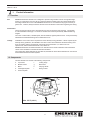
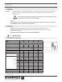
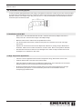
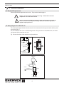
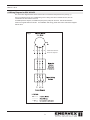
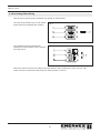
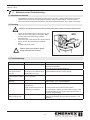
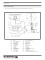
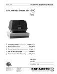
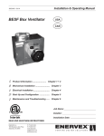
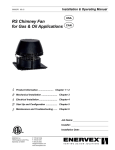
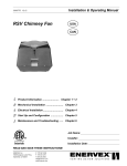
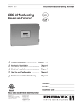
Installation & Operating Manual
3001391 06.14
GSV 200-450 Grease Fan
USA
CAN
Product Information ........................ Chapter 1 + 2
Mechanical Installation ......................... Chapter 3
Electrical Installation ............................. Chapter 4
Start Up and Configuration .................. Chapter 5
Maintenance and Troubleshooting ...... Chapter 6
Job Name:
Installer:
Installation Date:
EXHAUSTO Inc.
1200 Northmeadow Pkwy.
Suite 180
Roswell, GA 30076
P: 770.587.3238
F: 770.587.4731
T: 800.255.2923
[email protected]
us.exhausto.com
3001391 06.14
1. Product Information
1.1
1.2
1.3
1.4
2. Specifications
2.1 Dimensions & Capacities............................................................................ 5
3. Mechanical Installation
3.1 Positioning................................................................................................... 6
3.2 Installation on Steel Duct............................................................................ 6
3.3 Installation on Roof Curb............................................................................. 6
3.4 Termination of Venting System....................................................................7
3.5 Installation on Side Wall..............................................................................7
3.6 High Temperature Applications.....................................................................7
4. Electrical Installation
4.1
4.2
4.3
4.4
5. Start-up & Configuration
5.1 Start-up..................................................................................................... 11
5.2 Adjusting the Fan Speed...........................................................................11
Function...................................................................................................... 4
Components................................................................................................ 4
Shipping...................................................................................................... 5
Warranty...................................................................................................... 5
Electrical Requirements.............................................................................. 8
Wiring Diagram for GSV 250-315............................................................... 8
Wiring Diagram for GSV 400-450............................................................... 9
Start-up..................................................................................................... 10
6. Maintenance & Troubleshooting
6.1 Maintenance Intervals .............................................................................. 12
6.2 Cleaning.................................................................................................... 12
6.3 Troubleshooting......................................................................................... 12
6.4 Spare Parts Ordering................................................................................ 13
2
3001391 06.14
Symbol Legend:
The following terms are used throughout this manual to bring attention
to the presence of potential hazards or to important information
concerning the product.
Danger: Indicates an imminently hazardous situation
which, if not avoided, will result in death, serious injury or
substantial property damage.
Caution: Indicates an imminently hazardous situation which,
if not avoided, may result in personal injury or property
damage.
TO REDUCE THE RISK OF FIRE, ELECTRICAL SHOCK OR INJURY TO PERSONS,
OBSERVE THE FOLLOWING:
1. Use this unit in the manner intended by the manufacturer. If you have questions, contact the manufacturer at the address or telephone number listed on the front of the manual.
2. Before servicing or cleaning the unit, switch off at service panel and lock service panel to prevent power from being switched on accidentally.
3. Installation work and electrical wiring must be done by a qualified person(s) in accordance with applicable codes and standards.
4. Sufficient air is needed for proper combustion and exhausting of gases through the flue (chimney) of the fuel burning equipment to prevent backdrafting. Follow the cooking equipment manufacturer’s guidelines and safety standards such as those published by the National Fire Protection Association (NFPA), and the American Society for Heating, Refrigeration and Air Conditioning Engineers (ASHRAE) and the local code authorities.
5. This unit must be grounded.
TO REDUCE THE RISK OF INJURY TO PERSONS IN THE EVENT OF A CHIMNEY
FIRE, OBSERVE THE FOLLOWING:
1. Immediately close all dampers and/or air entrance openings to the cooking appliance. This includes doors.
2. Alert your patrons to the possible danger.
3. Inspect your cooking appliance and chimney surroundings for possible fire. If in doubt, alert your fire department.
4. Do not continue to use your appliance until it and your chimney have been throroughly inspected. Overheating can cause metal parts
to expand, buckle and crack. If you are not certain, have a certified chimney sweep disassemble all parts so they can be inspected and
cleaned.
5. Do not use salt or water on the fire in the cooking appliance. Salt is corrosive and water will cause a dangerous steam explosion. You might be able to control the fire by using ashes, sand or baking soda, since baking soda is an ingredient used for dry chemical fire
extinguishers. 6. After a chimney fire, when it is safe to do so, check internal locations such as an attic and under the roof and keep watching for two or three hours. There may be delayed smoldering and subsequent ignition, even if the fire inside the chimney has been controlled.
TO REDUCE THE RISK OF A CHIMNEY FIRE:
1. Keep chimney and grease fan clean.
2. Always turn ON fan when using the cooking appliance.
3. Do not leave cooking appliance unattended when in use.
CAUTION
1. Please read specification label on product for further information and requirements.
3
3001391 06.14
1.
Product Information
1.1 Function
Use
ENERVEX Model GSV Grease Fan is designed to provide a large exhaust volume at a high discharge velocity. It is intended for use as a part of a restaurant kitchen exhaust system and grease applications according to NFPA 96.The use of the ENERVEX Grease Fan is not restricted to any type of chimney or grease duct. However, always follow the exhaust-hood manufacturer’s instructions regarding the venting.
Construction
The fan housing is made of heavy cast aluminum and can be opened for easy cleaning. The impeller is of the backward inclined type. It is made of cast aluminum and has permanently attached balancing weights.
The motor is a direct-drive, variable speed, class H insulated, high temperature motor. It has permanently lubricated and sealed ball bearings and is maintenance free.
Listings
Installations must conform to the requirements of the authority having jurisdiction. Where required by the authority having jurisdiction, the installation must also conform to the NFPA 96. All electrical wiring must be in accordance with the requirements of authority having jurisdiction or, in absence of such requirements, with the National Electrical Code, NFPA 70.
ENERVEX Model GSV is tested and listed to UL Standard 705 for Power Ventilators and UL Standard 762 for Power Ventilators for Restaurant Exhaust Ventilators.
The model is also tested and listed to ULC-S645-93, Standard for Power Roof Ventilators for Commercial and Institutional Kitchen Exhaust Systems.
1.2 Components
The GSV Grease Fan consists of the following components:
a. Top section
f.
Locking hinge
b. Bottom section
g.
Bird screen
c.Motor
h.
Carrying handle
d. Centrifugal impeller
i.
Wiring conduit
e. Inlet for impeller
Fig. 1
Max. 575°F (300°C)
4
3/12
3001391 06.14
1.3 Shipping
Protection The fan is shipped in a corrugated cardboard box. If a transport securing device is attached (GSV 400 and GSV 450 only) to the bottom of the fan to hold the motor and impeller in place, do not remove it when unpacking the fan.
!
Do not remove the transport securing device until the fan is being installed on the duct or
the roof curb. The motor shaft could be damaged.
NOTE:
All single phase fans are shipped with a capacitor and junction box connected via conduit. The capacitor is located INSIDE the junction box. Please do not discard.
1.4 Warranty
ENERVEX products are warranted for a period of two (2) years following the date of invoice. Replacement or repair will be at ENERVEX’s discretion, provided factory inspection shows a defect in material or workmanship.
Complete warranty conditions are available from ENERVEX.
2. Specifications
2.1 Dimensions & Capacities
Model
GSV 200 GSV 250 GSV 315 GSV 400 GSV 450
Discharge
Vertical
Fan Type
Centrifugal Impeller
Max. Discharge Velocity FPM
1,729
2,222
2,771
2,752
4,134
Actual Discharge Velocity FPM 2.9xCFM 1.9xCFM 1.2xCFM 1.03xCFM 1.03xCFM
Voltage
VAC
1 x 120
3x208-240 / 3x380-420
RPM
1600
1680
1720
Amps
A
1.4
2.9
5.8
3.5
6.5
Power Ratings
kW
0.10
0.16
0.35
0.75
1.5
0.15
0.2
0.5
1.0
2.0
92
Weight
lbs
47
60
127
155
42
kg
18
26
58
70
16.94
Dimensions
A
in
11.03
13.20
16.94
23.23
430
mm
280
335
430
590
25.61
B x B in
15.37
19.11
25.61
25.61
650
mm
390
485
650
650
20.69
C x C in
12.22
15.17
20.69
20.69
525
mm
310
385
525
525
15.76
DØ
in
7.88
9.85
15.76
15.76
400
mm
200
250
400
400
5.12
E
in
3.15
3.94
5.12
8.54
130
mm
80
100
130
217
Soft Start Required
No
No
No
Yes 1)
Yes 1)
Variable Speed Motor
Yes
Yes
Yes
Yes
Yes
FA Sones
3.9
6.3
7.8
8.3
1) Not required if using a VFD
5
3001391 06.14
3. Mechanical Installation
3.1 Positioning
In accordance with NFPA 96, roof mounted fans shall have their discharge outlet at least 40 inches above the roof surface.
3.2 Installation on Steel Duct
•
Insert the adapter (FR) into the grease duct, where the long collar engagement ensures safe anchoring (See Fig. 2). If necessary, the adapter can be secured by means of long self-tapping stainless steel screws into the side of the collar through the chimney wall. Do not obstruct the grease flow.
•
Place the neoprene gasket (sold separately) on top of the adapter.
•
Remove the transport securing device (if present) holding the motor shaft and impeller in place.
•
Place the fan on the neoprene gasket centered over the cutout.
•
Open the fan and secure the fan onto the adapter, through the pre-drilled holes in the bottom, with lag bolts or self-tapping sheet metal screws, one at each corner.
Check the gasket to insure that it forms a complete seal.
•
!
Fig. 2
Caution: Never place hands or fingers on top of
fan base when closing
FR
3.3 Installation on Roof Curb
•
If the fan is supplied with a curb cap, secure the cap to the roof curb with self-tapping sheet metal screws (see Fig. 3).
•
Place the neoprene gasket on the top of the curb cap with the hole centered over the curb cap opening (sold separately). •
Remove the transport securing device (if present) holding the motor shaft and impeller in place.
•
Place the fan on the neoprene gasket centered over the cutout.
•
Open the fan and secure the fan onto the roof curb, through the pre-drilled holes in the bottom, with lag bolts or self-tapping sheet metal screws, one at each corner.
Check the gasket to insure that it forms a complete seal.
•
Fig. 3
!
Caution: Never place hands or fingers on top of
fan base when closing
6
3001391 06.14
3.4 Termination of Venting System
In order to achieve optimal performance and energy consumption for the RS Fan or GSV Fan, the duct must be installed as shown below and the distances observed. From the last elbow to the termination point the distance has to be 3 times the diameter of the flue. For example if you using 12in flue (12 X 3 = 36in). So the distance from the last elbow to the fan termination point should be 36 inches.
3.5Installation on Side Wall
•
Make sure the vent terminates flush with the wall. Insert the steel chimney adapter and secure it safely to the wall. Seal around the edges of the adapter flange.
•
Mark the locations of the wall anchors and predrill holes for them.
• Turn the fan upside-down and lay a bead of hi-temp silicone on the base close to the outer edge (not shown).
•
Open the fan and secure the fan onto the adapter with wall anchors, through the pre drilled holes in the bottom. Make sure the conduit is located on one of the sides. Never on the upside or downside.
•
Seal around the fan base to make sure it is watertight and no water can slip in between the fan and the adapter. Do not block the 4 drain holes.
3.6High Temperature Applications
•
If the fan is used for applications that exceed its temperature rating, dilution bolts must be used.
•
Install the dilution bolts in the outer holes of the fan base.
•
Adjust the height of the dilution gap by adjusting the dilution bolts, so the temperature of the exhaust going through the fan does not exceed the fan’s temperature rating.
•
Be aware the dilution bolts will have a negative impact on the fan’s actual capacity and a stronger fan model may be required. For more information, please refer to the installation manual a
accompanying the dilution bolts.
7
3001391 06.14
4.
Electrical Installation
4.1 Electrical Requirements
Power requirements depend on the fan size. They can be found on page 4.
!
!
Danger: Turn off electrical power before servicing. Contact with live electric
components can cause shock or death.
Notice: If any of the original wire supplied with the system must be replaced, use
similar wire of the same temperature rating. Otherwise, insulation may melt or
degrade, exposing bare wire.
4.2 Wiring Diagram for GSV 250-315
The connection diagram below shows how the fan is connected to the fan speed control and the power source (see Fig. 6).
Use a 2-conductor wire of min. 14 AWG with ground. Wiring must be run outside the duct, but can be run between the duct and the roof curb.
Fig. 5 shows the wiring of the capacitor in the junction box.
Fig. 4
Fig. 5
To fan
Gr
Red
Fan *)
ee
n
Bl
White
Junction box *)
Repair switch
ac
k
ck
Bla
White
To power
Fan speed control *)
*) supplied by EXHAUSTO
Fig. 6
Variable Speed
Fan Motor
Black
Red
Fan Motor
White
Capacitor
LEGEND:
Factory Wired
Field Wiring (14AWG)
Connection (wire nut)
2-pole doublethrow switch
Fan speed
control
Neutral
Hot
1 x 120 VAC, 60 Hz
8
3001391 06.14
4.3Wiring Diagram for GSV 400-450
The connection diagram below shows how the fan is connected to the power source (see Fig. 7).
Use a 3-conductor wire of min. 14 AWG with ground. Wiring must be run outside the duct, but can run between the duct and the roof curb.
If variable speed is required, a variable frequency drive (VFD) can be used. This will eliminate the need for a magnetic starter as shown. For installation and wiring, please refer to the instructions shipped with the VFD.
5
2
3
4
1
Fig. 7
9
Termination of 4 & 5
wires not required
3001391 06.14
4.4 Dual Voltage Motor Wiring
GSV 400-450 can operate at either 3x208-230 VAC (default) or 3x440-480 VAC.
The motor wiring terminals in Fig. 8 show default jumper positions for 3x208-230 VAC operation.
If the application requires 3x440-480 VAC operation, the jumper positions must be changed according to Fig. 9.
After wiring, make sure the motor is rotating in the proper direction. This is marked on the motor end cover. If the rotation is incorrect, swap the two wires going to the motor terminals, U1 and W1.
Fig. 8
Fig. 9
10
3001391 06.14
5. Start-up and Configuration
5.1 System Testing
•
Check the voltage with the motor nameplate rating.
• Check that the transport securing device holding the motor shaft and impeller in place has been removed.
•
•
Determine if the impeller is free and has not been subject to misalignment in shipping or installation.
Apply power and check that the impeller is rotating in the direction of the arrow on the side of the top motor cover. All ENERVEX fans run in a clockwise direction when viewed from the top. Double check if three phase motor is tested on temporary wiring. Switching any two leads will reverse the rotation.
5.2 Adjusting the Fan Speed
Start all heating appliances connected to the chimney with the fan installed. Set the fan speed control to the speed where no spillage is experienced anywhere in the system.
11
3001391 06.14
6.
Maintenance and Troubleshooting
6.1 Maintenance Intervals
The ENERVEX Grease Fan is designed for prolonged use. For dirty or grease-laden exhaust, inspect the impeller after (3) months and set up a periodic inspection based on these findings. Clean as required.
The fan motors are equipped with permanently lubricated sealed ball bearings. They require no lubrication.
6.2 Cleaning
!
•
•
•
•
!
Warning: Do not open the motor housing unless power to the grease fan has been disconnected
Loosen the two Phillips screws in the front of the unit.
Tilt the top of the fan by lifting on the handle. Make sure the locking arm holds the top of the fan
before letting go.
If necessary, use grease remover and a high-pressure cleaner to clean the impeller and the inside fan base.
A scraper may also be used.
Caution: Never place hands or fingers
on top of fan base when closing.
6.3 Troubleshooting
Problem
The fan is not operating.
Possible Cause
No power to the fan.
What to do
Check the power supply wires in the junction box by the fan.
Check the circuit breaker.
Check that the fan is actually turned ON.
The fan is not running
The capacitor is improperly
Check the connections inside the junction box. The capacitor
at full speed and/or is
connected or not connected at all must be installed according to wiring diagram.
humming.
(single-phase fans only).
The fan is rotating
Phase sequence in the power to Swap two phases in the junction box.
backwards (RSV 400/450 the fan is reversed.
only).
The fan is vibrating
The motor shaft is damaged.
Turn the power off immediately. Open the fan and check if the
vigorously.
shaft is straight. If not, contact ENERVEX.
The fan is noisy.
A transportation device has not
Remove the transportation device.
been removed.
Foreign matter is stuck in the fan. Turn off the power and remove the foreign article.
A ball bearing is damaged.
Turn off the power. Wait for the motor to stop revolving. Spin
the wheel and listen for any grinding noise from the motor. If
necessary, replace bearing.
The fan stops in the
The motor is overheating.
Check the flue gas temperature below the fan. The temperature
middle of a firing cycle.
should not exceed 400°F during continuous operation. Call
ENERVEX.
12
3001391 06.14
6.3Spare Parts Ordering
When ordering spare parts, please have the model number and part position number available
Red
White
01Motor
02
Motor mounting plate
03
Screw - SS (2)
04
Washer - SS (2)
05
Housing (top)
06
Housing (base)
07
Impeller seat
08
Bird screen
09
Top plate
10
Aluminum Impeller
12
Locking hinge
13
Cooling vane
14
Screw - SS (4)
17
Screw - SS (4)
21
22
23
24
29
31
41
42
60
61
62
63
64
65
13
Motor housing insulation
Screw - SS (2)
Washer - SS (2)
Screw - SS
Screw - SS (4)
Rivet (2)
Neoprene Gasket
Rivet (12)
3/8” Conduit
3/8” Connector
Junction box with blank cover
Wire nuts (4)
Capacitor (1x120V fans only)
Wiring diagram (mounted on inside cover)
3001391 06.14
Notes
EXHAUSTO Inc.
1200 Northmeadow Pkwy.
Suite 180
Roswell, GA 30076
P: 770.587.3238
F: 770.587.4731
T: 800.255.2923
[email protected]
us.exhausto.com
3001391 06.14
Notes
EXHAUSTO Inc.
1200 Northmeadow Pkwy.
Suite 180
Roswell, GA 30076
P: 770.587.3238
F: 770.587.4731
T: 800.255.2923
[email protected]
us.exhausto.com
3001391 06.14
EXHAUSTO Inc.
1200 Northmeadow Pkwy.
Suite 180
Roswell, GA 30076
P: 770.587.3238
F: 770.587.4731
T: 800.255.2923
[email protected]
us.exhausto.com