1
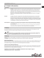
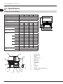
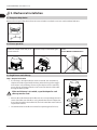
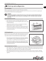
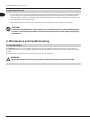
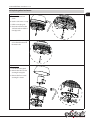
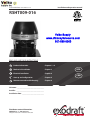
Installation and operation manual
3100153 RSHT009 - 016 2012-11-15
RSHT009-016
Volko Supply
www.chimneyfansource.com
800 685 8263
READ AND SAVE THESE INSTRUCTIONS!
Product information Chapters 1 + 2
Mechanical installation Chapter 3
Electrical installation Chapter 4
Start up and configuration Chapter 5
Maintenance and troubleshooting Chapter 6
Job name:__________________________________
Installer: ___________________________________
Installation date: ____________________________
Distributor contact information:
ENERVEX Inc. • T: 800.255.2923
[email protected] • www.enervex.com
USA
CAN
3100153 RSHT009 - 016 2012-11-15
Contents
2
1. Product information
2. Specifications
3. Mechanical installation
4. Electrical installation
5. Start-up and configuration
6. Maintenance and troubleshooting
1.1 Function . . . . . . . . . . . . . . . . . . . . . . . . . . . . . . . . . . . . . . . . . . . . . . . . . . . . . . . . . . . . . . . . . . . . . . . . 3
1.2 Shipping . . . . . . . . . . . . . . . . . . . . . . . . . . . . . . . . . . . . . . . . . . . . . . . . . . . . . . . . . . . . . . . . . . . . . . . . 3
1.3 Warranty . . . . . . . . . . . . . . . . . . . . . . . . . . . . . . . . . . . . . . . . . . . . . . . . . . . . . . . . . . . . . . . . . . . . . . . . 3
2.1 Dimensions and capacities . . . . . . . . . . . . . . . . . . . . . . . . . . . . . . . . . . . . . . . . . . . . . . . . . . . . . . . 4
2.2 Planning ahead . . . . . . . . . . . . . . . . . . . . . . . . . . . . . . . . . . . . . . . . . . . . . . . . . . . . . . . . . . . . . . . . . . 5
3.1 Transport safety device . . . . . . . . . . . . . . . . . . . . . . . . . . . . . . . . . . . . . . . . . . . . . . . . . . . . . . . . . . 6
3.2 Prior to operation . . . . . . . . . . . . . . . . . . . . . . . . . . . . . . . . . . . . . . . . . . . . . . . . . . . . . . . . . . . . . . . . 6
3.3 Single fan on steel chimney . . . . . . . . . . . . . . . . . . . . . . . . . . . . . . . . . . . . . . . . . . . . . . . . . . . . . . 6
3.4 Single fan on brick chimney . . . . . . . . . . . . . . . . . . . . . . . . . . . . . . . . . . . . . . . . . . . . . . . . . . . . . . 7
3.5 Multiple fans on steel chimney . . . . . . . . . . . . . . . . . . . . . . . . . . . . . . . . . . . . . . . . . . . . . . . . . . . 8
3.6 Multiple fans on a brick chimney – oversized flue . . . . . . . . . . . . . . . . . . . . . . . . . . . . . . . . . 8
4.1 General . . . . . . . . . . . . . . . . . . . . . . . . . . . . . . . . . . . . . . . . . . . . . . . . . . . . . . . . . . . . . . . . . . . . . . . . . 9
4.2 Connection and wiring diagram for single fan with fan speed control . . . . . . . . . . . . . . 9
4.3 Connection and wiring diagram for two fans with fan speed control . . . . . . . . . . . . . 10
4.4 Connection and wiring diagram for single fan with EFC211 . . . . . . . . . . . . . . . . . . . . . 10
5.1 System testing . . . . . . . . . . . . . . . . . . . . . . . . . . . . . . . . . . . . . . . . . . . . . . . . . . . . . . . . . . . . . . . . . 11
5.2 Testing fireplace or stove . . . . . . . . . . . . . . . . . . . . . . . . . . . . . . . . . . . . . . . . . . . . . . . . . . . . . . . 11
5.3 Testing pizza oven . . . . . . . . . . . . . . . . . . . . . . . . . . . . . . . . . . . . . . . . . . . . . . . . . . . . . . . . . . . . . 11
5.4 Operating fireplace and stove . . . . . . . . . . . . . . . . . . . . . . . . . . . . . . . . . . . . . . . . . . . . . . . . . . 11
5.5 Operating pizza oven . . . . . . . . . . . . . . . . . . . . . . . . . . . . . . . . . . . . . . . . . . . . . . . . . . . . . . . . . . 12
6.1 Care and cleaning . . . . . . . . . . . . . . . . . . . . . . . . . . . . . . . . . . . . . . . . . . . . . . . . . . . . . . . . . . . . . 12
6.2 Replacing wheel and motor . . . . . . . . . . . . . . . . . . . . . . . . . . . . . . . . . . . . . . . . . . . . . . . . . . . . 13
6.3 Chimney cleaning intervals . . . . . . . . . . . . . . . . . . . . . . . . . . . . . . . . . . . . . . . . . . . . . . . . . . . . 14
Notes . . . . . . . . . . . . . . . . . . . . . . . . . . . . . . . . . . . . . . . . . . . . . . . . . . . . . . . . . . . . . . . . . . . . . . . . . . . . . 15
Symbol legend
The following terms are used throughout this manual to bring attention to the presence of potential hazards
or to important information concerning the product.
DANGER
Indicates an imminent hazardous situation which,
if not avoided, will result in death, serious injury or
substantial property damage.
CAUTION
Indicates an imminent hazardous situation which,
if not avoided, may result in personal injury or
property damage.
TO REDUCE THE RISK OF FIRE, ELECTRICAL SHOCK OR INJURY TO PERSONS,
OBSERVE THE FOLLOWING:
1. Use this unit in the manner intended by the manufacturer. If
you have questions, contact the manufacturer’s distributor at the
address or telephone number listed on the front of the manual.
Association (NFPA), and the American Society for Heating, Refrigeration and Air Conditioning Engineers (ASHRAE), and the local
code authorities.
2. Before servicing or cleaning the unit, switch off at service panel
and lock service panel to prevent power from being switched on
accidentally.
5. This unit must be grounded.
How to use this manual
This installation manual does not contain any system design
3. Installation work and electrical wiring must be done by a quali- documentation. System design documentation is available from
fied person(s) in accordance with applicable codes and standards. ENERVEX.
4. Follow the appliance manufacturer’s guidelines and safety
Accessories and variable frequency drives are not covered by this
standards such as those published by the National Fire Protection manual. Please refer to these component’s individual manuals.
3100153 RSHT009 - 016 2012-11-15
1. Product information
1.1 Function
Use exodraft model RSHT chimney fan is a chimney top mounted ventilator that is designed to provide
large flue gas volume capacities. It is intended for use with solid fuel but can also be used for nonsolid fuel provided a safety system is part of the installation (refer to the manual: “RS for Gas & Oil
Applications”). The use of the RSHT chimney fan is not restricted to any type of chimney, because the
fan creates a negative pressure (below atmospheric) in the chimney.
Typical uses are: Controlling the draft for a residential solid fuel fired boiler, fireplace, stove, BBQ, or
pizza oven.
Function The RSHT chimney fan is designed to be able to withstand the high temperatures associated with
wood burning and to minimize the creosote buildup in the chimney flue and on the chimney fan.
The axial vane construction provides a self-cleaning effect. This product is developed to prevent draft
problems by creating a mechanical draft in venting systems and thereby also increasing the capacity
and efficiency of a venting system. Though the chimney fan is not limited to such use, it is perfect for
use with fireplaces, barbecues, pizza ovens and wood stoves.
Code compliance Installations must conform to requirements of the authority having jurisdiction. Where required by
the authority having jurisdiction, the installation must also conform to the Standard for Draft Equipment and NFPA 211.
All electrical wiring must be in accordance with the requirements of authority having jurisdiction or,
in the absence of such requirements, with the National Electrical Code, NFPA70.
1.2 Shipping
The packing list (attached to one of the packages) clearly lists all items in the shipment and each package has a label
showing the contents. Check the list against all materials on the job site for completeness.
NOTE
All single phase fans are shipped with a capacitor and junction box connected via conduit. The
capacitor is located INSIDE the junction box. Please do not discard.
1.3 Warranty
exodraft products are warranted for a period of two (2) years following the date of invoice. Replacement or repair will be
at exodraft’s discretion, provided factory inspection shows a defect in material or workmanship.
2-Year Factory Warranty
We promise the original user that we will replace or repair as we may elect, any part or parts of the new RSHT Chimney Fan
which are defective in material or workmanship without charge for parts and labor (not including labor for dismantling
and installation, freight, etc.) during the first 2-years following the date of installation.
10-Year Corrosion Perforation Warranty
We promise the original user that we will replace or repair as we may elect, any part or parts of the RS Chimney Fan which
are perforated due to corrosion without charge for parts or labor (not including dismantling and installation, freight, etc.)
during the first 10-years following the date of installation.
Complete warranty conditions are available at www.enervex.com or request a copy at:
[email protected] or at tel.: 1-800.255.2923.
3
3100153 RSHT009 - 016 2012-11-15
2. Specifications
4
2.1 Dimensions and capacities
Model
RS009
RS012
Discharge
RS014
RS016
Fan Type
Axial Vane
Totally enclosed, Variable speed, Class F
V AC
RPM
1x120
1780
1780
1780
1730
CFM
0.0 Ps
275
530
830
1430
Amperage
Amps
0.85
1.25
3.50
4.50
Motor Output
HP
0.11
0.13
0.34
0.47
kW
0.08
0.10
0.25
0.35
lbs
25.6
33.5
41.9
47.2
kg
11.6
15.2
19.0
21.4
in
11.7
12.8
14.6
15.7
mm
298
325
372
400
in
11.7
14.3
16.6
18.8
mm
296
364
422
478
in
10.8
13.5
15.6
17.4
mm
275
344
395
441
in
3.0
3.3
3.9
3.9
mm
75
85
100
100
in
8.7
11.0
13.0
15.0
mm
220
280
330
380
Weight
A
BxB
C
D
E
Temperature
Rating
Interm.
Cont.
A
Voltage
D
Motor Type
Dimensions
C
Horizontal
E
B
1.330 °F/721 °C
930 °F/499 °C
1
Junction box
2Conduit/cord
3Motor
4
Motor housing
5
Motor plate
6
Bird screen
7
Base plate
8
Locking nut
9Inlet
10
Axial vane
11Hinges
12
Capacitor (inside junction box)
13
Cooling wheel
3100153 RSHT009 - 016 2012-11-15
2.2 Planning ahead
1. Observe proper combustion air requirements.
2. Provide a firm support system for the chimney fan.
3. Determine the type of system involved.
4. Observe proper safety measures are taken to assure safe use of the wood burning appliances.
Combustion air requirements
Provisions for combustion air must be in accordance with applicable local codes.
Adequate fresh air must be provided for combustion; otherwise, improper operation and inadequate
venting of deadly flue gases may result.
Support system
Prior to installation of the chimney fan, it must be assured the chimney can safely carry the weight of
the chimney fan.
A steel chimney should be well supported at the roof penetration point. If the chimney extends more
than 20’ above the roof, the chimney and the fan should be secured by wires attached on the chimney and on the roof at 2 to 3 different points.
Brick chimneys usually do not need any kind of support to carry the weight of the chimney fan.
System type Fireplaces and wood stoves used in residences normally operate in a relatively stable environment,
where no major pressure fluctuations occur. However, speed adjustments and adjustment of airintakes are required as the wood burns and new wood is added to the fire.
Fireplaces used in restaurants are exposed to major pressure changes. Doors open, doors close,
kitchen exhaust fans pull out air, etc. Spillage can easily occur.
Wood-fired pizza ovens and barbecues are normally installed in restaurant kitchens where kitchen exhaust fans are operating. Consequently, the operator should pay attention to the fact that even with a
well balanced exhaust system, it will be necessary to adjust the fan speed in order to avoid spillage.
5
3100153 RSHT009 - 016 2012-11-15
6
3. Mechanical installation
3.1 Transport safety device
Remove the transport safety device from the vane and make sure that the vane can revolve without hindrance.
3.2 Prior to operation
To open the fan: Remove the two nuts
at the front and pull out the lock pin at
the rear of the fan.
Too secure the fan in open position
place the lock pin in the bracket again.
Always mount the fan in vertical
position.
DO NOT MOUNT HORIZONTALLY
3.3 Single fan on steel chimney
Step 1: Prepare fan location
yy If a stack cap is already installed, it must be removed. The steel chimney
adapter (SCA) slides right into the chimney, where the long collar engagement ensures safe anchoring. If necessary, the adapter can be secured by
means of long self-tapping stainless steel screws into the side of the collar
through the chimney wall.
If the steel chimney is air cooled, a special adapter for such
chimney must be used.
yy Measure the inside diameter of the flue and cut a corresponding hole in the
center of the fiber mat. If the flue is so big that the throat in the adapter has
been reduced to fit the throat of the fan, the hole in the fiber mat should correspond to the throat.
yy The aluminum foil on the fiber mat must face upward (against fan base).
3100153 RSHT009 - 016 2012-11-15
Step 2: Preparation of exodraft fan
yy Locate the installation brackets in the slots going through the fan
base part, using the bolts and nuts supplied to secure the brackets. If
the flue diameter is larger than the chimney fan inlet, the bracket can
be installed underneath the base part. Note that the bolts must be
installed from the bottom side.
yy Adjust the final position of the installation brackets ensuring that
there is a small gap between the brackets and the flue wall/adapter
throat.
yy Tighten the nuts. If the brackets touch the flue wall, it may create
some vibration noise.
Step 3: Attaching the fan
yy The chimney fan is now ready for installation on the top of the chimney.
yy Place the fiber mat with the aluminum foil facing upwards on the top
of the adapter, and place the fan on top of the mat.
yy High temperature silicone can be applied on the side of the mat, but is
not required.
yy It can also be painted. It is not necessary to bolt the fan to the chimney.
Step 4: Sealing the slots
yy To avoid rainwater to enter the chimney the 4 slots must be sealed with silicone.
CAUTION
Under conditions with extremely strong winds surrounding the top
of the chimney, the chimney fan must be secured by steel wires
supplied with the fan.
3.4 Single fan on brick chimney
Step 1: Prepare fan location
yy The installation procedure is the same whether the flue is round
or square. If a clay tile flue liner is installed, it might stick up a few
inches. Cut it back so it is flush with or no more than 1/2 inch above
the chimney crown.
yy Measure the inside diameter of the flue, cut a corresponding hole in
the fiber mat leaving a minimum distance of 3/4” to any side of the
fiber mat.
yy The aluminum foil on the fiber mat must face upwards (against fan
base).
Step 2: Preparation of fan
yy Locate the installation brackets in the slots going through the fan
base part, using the bolts and nuts supplied to secure the brackets.
If the flue diameter is larger than the chimney fan inlet, the bracket
can be installed underneath the base part. Note that the bolts must
be installed from the bottom side.
yy Adjust the final position of the brackets ensuring that there is clearance between the brackets and the flue wall. If the brackets touch
the wall, it may generate some vibration noise.
7
3100153 RSHT009 - 016 2012-11-15
8
Step 3: Attaching the fan
yy The chimney fan is now ready for installation on the top of the chimney. Place fiber mat with the aluminum foil facing upwards on the
top of the chimney, and place the fan on top of the mat.
yy High temperature silicone can be applied on the side of the mat, but
is not required. It can also be painted.
yy It is not necessary to bolt the fan to the chimney.
Step 4: Sealing the slots
yy To avoid rainwater to enter the chimney the 4 slots must be sealed with silicone.
CAUTION
Under conditions with extremely strong winds surrounding the top of the chimney, the chimney
fan must be secured by steel wires supplied with the fan.
3.5 Multiple fans on steel chimney
yy If two or more chimney fans are required to create sufficient draft, installation procedures are the same as for single
fan installation on a steel chimney. The only difference is that the
fans are sitting next to each other on the top of the chimney. A special adapter plate is required (14 GA or thicker).
yy When installing multiple fans, it is extremely important that the
fans are of the same model and size, and they must be controlled in
tandem by one (1) motor speed control.
3.6 Multiple fans on a brick chimney – oversized flue
yy If two or more fans are required to create sufficient draft, a special
adapter plate is required. The adapter plate should be made of
stainless steel (14 GA or thicker), depending on the size and the fan
models used.
yy The two holes in the plate should match the throat diameter of the
fan model used and the distance from center to center should be at
least equal to the fan width (dimension “B” in 1.5. Dimensional data).
yy The adapter should be sealed with silicone and bolted onto the top.
When installing multiple fans, it is extremely important that the fans
are of the same model and size, and they must be controlled in tandem by one (1) motor speed control.
yy A similar approach should be taken if the flue size exceeds the fan
base dimensions. The adapter plate should be sized so it covers the
flue and secured. A hole should be cut in the center of the plate and
the fan mounted centered over the hole.
3100153 RSHT009 - 016 2012-11-15
4. Electrical installation
9
4.1 General
DANGER
Turn off electrical power before servicing.
Contact with live electric components can cause shock or death.
All electrical wiring must be in accordance with requirements of authority having jurisdiction or, in absence of such requirements, with National Electrical Code NFPA 70 — latest edition. If an external electrical source is utilized, system must
be electrically grounded in accordance with requirements of the authority having jurisdiction or, in the absence of such
requirements, with the National Electrical Code NFPA 70 — latest edition.
Power requirements for the system depends on the fan size. Electrical requirements are:
yy RSHT009 1 x 120 V/60 Hz 0.85 Amps
yy RSHT012 1 x 120 V/60 Hz 1.25 Amps
yy RSHT014 1 x 120 V/60 Hz 3.50 Amps
yy RSHT016 1 x 120 V/60 Hz 4.50 Amps
The exodraft chimney fans have a split capacitor motor with infinitely variable speed.
The fan speed control supplied is rated 1 x 120 V/60 Hz and 5 Amps. It has an adjustable low voltage set point
of min. 65 V +/- 5 V.
NOTICE
If any of the original wire supplied with the system must be replaced, use similar wire of the same
temperature rating. Otherwise, insulation may melt or degrade, exposing bare wire.
4.2 Connection and wiring diagram for single fan with fan speed control
The wiring diagram below shows the wiring of the chimney fan and how it is connected to the fan speed control.
Chimney fan
GREEN
BLACK
WEATHERPROOF BOX
RED
Junction
box
WHITE
FAN
MOTOR
N
120/1/60
FSC, fan
Speed control
L
NOTES:
1
FAN SPEED
CONTROL
All wiring must be in
flexible or rigid metal
conduit
THE DISCONNECT MEANS AND CIRCUIT PROTECTION ARE TO
BE PROVIDED BY THE INSTALLER OF THIS DEVICE
LEGEND:
24 VAC
120 VAC
3100153 RSHT009 - 016 2012-11-15
4.3 Connection and wiring diagram for two fans with fan speed control
The diagrams below show the wiring of two chimney fans and how they are connected to the fan speed control.
Chimney fans
FAN
MOTOR
FAN
MOTOR
GREEN
BLACK
WHITE
WEATHERPROOF BOX
RED
GREEN
BLACK
WEATHERPROOF BOX
WHITE
Junction box
RED
Junction box
FSC, fan
Speed control
N
120/1/60
L
FAN SPEED
CONTROL
NOTES:
WEATHERPROOF
BOX
All wiring must be in
flexible or rigid metal
conduit
1 THE DISCONNECT MEANS AND CIRCUIT PROTECTION ARE TO
BE PROVIDED BY THE INSTALLER OF THIS DEVICE
LEGEND:
24 VAc
120 VAC
4.4 Connection and wiring diagram for single fan with EFC211
The diagrams below show the wiring of a single chimney fan when used in conjunction with an EFC211 control
Chimney fan
GREEN
BLACK
WHITE
Junction
box
with control unit
ORANGE
RED
FAN
MOTOR
9 10 11 12 13 14 15 16 17 18 19
4
3
2
1
All wiring must be in
flexible or rigid metal
conduit
120/1/60
5
FAN CONTROL UNIT
NOTES:
1
THE DISCONNECT MEANS AND CIRCUIT PROTECTION ARE TO
BE PROVIDED BY THE INSTALLER OF THIS DEVICE
LEGEND:
24 VAC
120 VAC
N
6
L
7
1
8
2
3
4
5
6
All wiring must be in
metal conduit or
shielded cable
MAIN CONTROL UNIT
WEATHERPROOF BOX
EFC211, fan
Speed control
10
3100153 RSHT009 - 016 2012-11-15
5. Start-up and configuration
5.1 System testing
Before any adjustments are made to the system, follow these procedures:
Turn the chimney fan ON and make sure that it is operating. Increase and decrease the speed of the fan by adjusting the
fan speed control to make sure it is operating properly.
DANGER
Check heating appliances (water heater, furnace, etc.) for proper operation while the chimney
fan is operating. Make sure no flue gases are spilling out as this can lead to carbon monoxide
poisoning.
5.2 Testing fireplace or stove
yy Place a few logs on a grate or on the floor of the fireplace or stove.
yy Before lighting the fire, set the fan at high/full speed (on stoves, open
air intake completely).
yy Light the fire and make sure there is no spillage from the fireplace
opening or from the stove’s air intake (see figure).
yy When the fire has caught on, reduce the speed of the chimney fan to
a point where it still removes the flue gases safely. Mark this setting
on the fan speed control cover, as this will be the operating position/
speed of the chimney fan.
5.3 Testing pizza oven
Most pizza ovens consist of a dome with a front opening that can be closed
with a cast iron door. Above the opening a hood connected to the flue assures smoke and odors are collected and removed safely (see figure).
yy Place a few logs in the back of the dome and set the fan at high/full
speed. Light the fire. Turn on all exhaust fans (range hoods, etc.) and
make sure there is no spillage from the hood into the room.
yy When the fire has caught on, reduce the speed of the chimney fan to
a point where it still removes the flue gases safely. Mark this setting
on the fan speed control cover, as this will be the operating position/
speed of the chimney fan.
5.4 Operating fireplace and stove
yy Prior to starting a fire, set the fan at high/full speed and start the fire following the normal instructions for burning a
fire in a fireplace or stove. After the fire catches on, after 3-5 minutes, reduce the speed of the chimney fan to a level
where it safely removes the flue gases and a perfect flame can be maintained.
yy When adding wood to the fire, it may be necessary to increase the fan speed for a short period of time. Following
this procedure will help conserve energy and at the same time assure a maximum heating output from the heating
appliance.
11
3100153 RSHT009 - 016 2012-11-15
5.5 Operating pizza oven
12
yy Prior to starting a fire, set the fan at high/full speed and start the fire following the oven manufacturer’s instructions
or, in the absence of such instructions, normal instructions for burning a fire in a fireplace or stove. After the fire
catches on, after 3-5 minutes, reduce the speed of the chimney fan to a level where it safely removes the flue gases
and a perfect flame can be maintained.
yy When adding wood to the fire, it may be necessary to increase the fan speed for a short period of time.
CAUTION
Do not over-fire the fireplace, stove or pizza oven. Small deposits of creosote could be ignited
and start a small chimney fire which could cause the chimney flue to reach a dangerously high
temperature.
6. Maintenance and troubleshooting
6.1 Care and cleaning
The exodraft Chimney Fan is designed for prolonged use. The fan should be inspected at least once a year when the
chimney is inspected. Creosote and other deposits should be removed from the fan blades and the bottom of the motor
housing.
The top of the fan is hinged and can be opened in order to ease the cleaning.
WARNING
Do not open the motor housing unless power to the chimney fan has been disconnected.
3100153 RSHT009 - 016 2012-11-15
6.2 Replacing wheel and motor
13
Replace wheel
A. Loosen the insert hex
screw
B. Use the 1/4” screw as a tap
C. Pull the vane plug out
D. Unscrew and remove the
1/4” bolt at the end of the
vane pipe axle
A
D
C
B
E. Use a 3/8” bolt min. length
5.5” to draw the wheel of
the motor axle
E
Replace Motor
F. Loosen the cable gland
G. Remove the three screws
securing the top part
H. Remove the four screws
securing the motor
G
F
H
3100153 RSHT009 - 016 2012-11-15
6.3 Chimney cleaning intervals
14
It is extremely important to keep the chimney flue clean from creosote and
deposits. Creosote is the major cause of chimney fires.
Cleaning intervals depend on the use of the appliance. The more the appliance is used, the more often the chimney flue needs cleaning.
If a fireplace is used regularly (2-3 times a week), semi-annual chimney
cleaning may be required. If it is used every day, shorter intervals may be
required. Commercial use of wood-fired pizza ovens may require chimney
cleaning every 2-3 months.
No matter how much used, a chimney flue serving wood-fired appliances
should be cleaned and inspected at least once every year.
NOTE
The chimney should be cleaned by a trained professional.
We recommend using a Certified chimney sweep certified by Chimney Safety Institute of America.
You can find a Certified Chimney Sweep at www.csia.org or www.ncsg.org
or by calling (317) 837-5362 or (317) 837-1500.6.3 Troubleshooting
Observation
Problem
Solution
There is no power going to
the fan
– The circuit breaker may be off
– Fan speed control is off
– Bad electrical connections
– Check the circuit breaker
– Turn fan speed control on
– Check and correct problem
There is power to the fan but
it is not operating
– Bad electrical connections
– Check and correct problems with connections. Pay special attention to
the wiring in the junction box
– Increase the setting with the plastic screw on the fan speed control’s front
plate
– Replace the fan speed control
There is power to the fan but
it hums and does not turn
– The motor run capacitor may be
bad.
– Creosote may stick
– Check capacitor and replace if necessary
The fan seems to work fine,
but there is not enough draft
– The fan may be undersized
– Replace with a larger fan
The fan vibrates
– The motor shaft may be bent
– Replace motor
There is airflow noise from
the fireplace opening
– The flue is undersized.
– The fan is oversized and running
too fast
– There is not much to do about it. Try to reduce the firep
– Reduce the fan speed
Mechanical noise can be
heard
– Foreign matter may be stuck
– Motor bearings may be worn out
– Remove matters
– Replace bearings
– The fan speed control’s low voltage
setting is too low
– The fan speed control is bad
– Clean fan
Volko Supply
www.chimneyfansource.com
800 685 8263
lace opening
3100153 RSHT009 - 016 2012-11-15
Notes
15
Distributor in USA & Canada
ENERVEX Inc.
1685 Bluegrass Lake Parkway
Alpharetta
GA 30004
P: 770.587.3238
F: 770.587.4731
T: 800.255.2923
[email protected]
www.enervex.com
Volko Supply
www.chimneyfansource.com
800 685 8263
www.exodraft.com