1
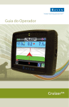
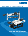
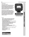
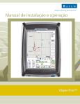
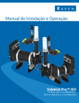
Operation Guide
Cruizer II™
(Software Version 3.2)
Disclaimer
While every effort has been made to ensure the accuracy of
this document, Raven Industries assumes no responsibility
for omissions and errors. Nor is any liability assumed for
damages resulting from the use of information contained
herein.
Raven Industries shall not be responsible or liable for
incidental or consequential damages or a loss of anticipated
benefits or profits, work stoppage or loss, or impairment of
data arising out of the use, or inability to use, this system or
any of its components. Raven Industries shall not be held
responsible for any modifications or repairs made outside our
facilities, nor damages resulting from inadequate
maintenance of this system.
As with all wireless and satellite signals, several factors may
affect the availability and accuracy of wireless and satellite
navigation and correction services (e.g. GPS, GNSS, SBAS,
etc.). Therefore, Raven Industries cannot guarantee the
accuracy, integrity, continuity, or availability of these services
and cannot guarantee the ability to use Raven systems, or
products used as components of systems, which rely upon
the reception of these signals or availability of these services.
Raven Industries accepts no responsibility for the use of any
of these signals or services for other than the stated purpose.
©Raven Industries, Inc. 2010, 2011, 2012, 2013
Contents
Overview. . . . . . . . . . . . . . . . . . . . . . . . . . . . . 2
Care and Maintenance . . . . . . . . . . . . . . . . . 3
Installation . . . . . . . . . . . . . . . . . . . . . . . . . . . 4
Initial Startup . . . . . . . . . . . . . . . . . . . . . . . . . 4
Home Screen . . . . . . . . . . . . . . . . . . . . . . . . . 6
GPS Status Icon. . . . . . . . . . . . . . . . . . . . . . 7
Starting Guidance . . . . . . . . . . . . . . . . . . . . . 8
Start a New Job and Load Field Features . . 8
Resume a Saved Job and Delete Jobs . . . 10
Guidance Screen . . . . . . . . . . . . . . . . . . . . . 11
Guidance Menu . . . . . . . . . . . . . . . . . . . . . . 13
Guidance Screen Modes . . . . . . . . . . . . . . 13
Starting A-B Guidance . . . . . . . . . . . . . . . . 13
A-B Guidance Path Tools . . . . . . . . . . . . . 14
Boundary Mapping Menu . . . . . . . . . . . . . . 14
Record a Zone or Field Boundary . . . . . . . 14
Field Area Display . . . . . . . . . . . . . . . . . . . 15
Field Review Mode . . . . . . . . . . . . . . . . . . . 16
Boundaries and Zones . . . . . . . . . . . . . . . . 16
Additional Field Review Mode Icons . . . . . 16
Field Markers . . . . . . . . . . . . . . . . . . . . . . . 17
Ending a Job . . . . . . . . . . . . . . . . . . . . . . . . 18
Powering Down the Cruizer II. . . . . . . . . . . 18
Tools Menu . . . . . . . . . . . . . . . . . . . . . . . . . 18
Favorites . . . . . . . . . . . . . . . . . . . . . . . . . . 18
System . . . . . . . . . . . . . . . . . . . . . . . . . . . 18
Vehicle . . . . . . . . . . . . . . . . . . . . . . . . . . . . 19
Computer . . . . . . . . . . . . . . . . . . . . . . . . . . 20
GPS . . . . . . . . . . . . . . . . . . . . . . . . . . . . . . 20
Favorites Menu . . . . . . . . . . . . . . . . . . . . . . 21
AccuBoom™ . . . . . . . . . . . . . . . . . . . . . . . . 22
Display . . . . . . . . . . . . . . . . . . . . . . . . . . . . . 25
File Maintenance . . . . . . . . . . . . . . . . . . . . . 26
Coverage Maps . . . . . . . . . . . . . . . . . . . . . . 27
Enabling Coverage Map Output . . . . . . . . . 27
Coverage Map Output . . . . . . . . . . . . . . . . 27
Using RTK Corrections . . . . . . . . . . . . . . . 28
Wireless Communication . . . . . . . . . . . . . . 29
Baud Rate Settings . . . . . . . . . . . . . . . . . . . 31
CAN Diagnostics . . . . . . . . . . . . . . . . . . . . 32
Updates . . . . . . . . . . . . . . . . . . . . . . . . . . . . 33
Troubleshooting . . . . . . . . . . . . . . . . . . . . . 34
System Connection Diagrams . . . . . . . . . . 36
Manual No. 016-0171-415 Rev. F
Kit Contents
Cruizer II Console
(P/N 063-0173-090) or
Cruizer II RTK Console
(P/N 063-0173-327)
RAM Mount Arm
(P/N 103-0159-011)
Accessory Power Cable
(P/N 420-1011-008)
AND EITHER:
Patch Antenna
(P/N 063-0172-101)
OR
Helix Antenna
(P/N 063-0172-480)
or MBA-6 Antenna
(P/N 063-0172-651)
Antenna Cable,
15’ (P/N 115-0171-117) or
20’ (P/N 115-0171-787)
Aerial Antenna
Mounting Plate
(P/N 063-0172-971)
1
Overview
The Cruizer II™ guidance system offers advanced guidance with an easy-touse touch screen. In addition, the Cruizer II simulates radar for speedcompensated applications and supplies Differential GPS data to other
controllers or optional systems such as:
• Raven SmarTrax™ or SmarTrax MD™ automated steering control.
• Raven TM-1™ Tilt Module for tilt-corrected guidance.
• Raven Glide Series AutoBoom™ automatic boom height management.
• Raven automatic section control features such as AccuBoom™,
SmartBoom™, AccuRow™, and SmartRow™.
• Raven SCS 400/600 Series consoles (e.g. SCS 440/450 or SCS 660/660).
Note: Contact a local Raven dealer for information on additional features or
options available for use with the Cruizer II
FIGURE 1. Back Panel of Cruizer II Console
RAM Mount
Power
Button
USB Ports
Antenna Port
Auxiliary Audio
Output Jack
CAN Port
Port
A and C
Port
B and D
Power Port
Warning: Cruizer II consoles with P/N 063-0173-090 or
063-0173-327 are NOT weather resistant.
Note: The 1/8” auxiliary audio output jack is designed to connect to a set of
external speakers for audible alarms (not currently available) from the
Cruizer II console.
This manual is designed for use with Cruizer II™ software version 3.2.
Updates for Raven manuals are available at the Applied Technology Division
web site:
www.ravenhelp.com
Sign up for e-mail alerts to receive notification when updates for Raven
products are available on the Raven web site.
Note: Be sure to delete existing or previous jobs from internal memory before
updating the Cruizer software.
Jobs started with software versions prior to 3.0 will not be compatible
with versions 3.0 or newer. It will not be possible to resume these jobs
after applying the software update and there may be issues deleting
jobs from internal memory.
2
Cruizer II™ Operation Guide
Care and Maintenance
• Harsh chemicals may damage the touch screen. Clean the touch screen
and console exterior as needed with a soft cloth dampened with glass
cleaner. Apply the cleaner to the cloth and then wipe the screen gently.
• Removing power from the console without shutting down the Cruizer II may
result in damage to the unit which will require the console to be returned for
service
• To avoid scratching the touch screen, do not use any type of sharp
instrument. Only a fingertip or an approved stylus should be used.
• Do not expose the Cruizer II console to precipitation, condensation, or other
liquids. Store the console in a dry environment when not in use.
• The suction cup is not meant as a permanent mounting solution. It is
recommended that the suction mount only be used when the console is in
operation. Clean the mounting surface with alcohol or a similar cleaner prior
to attaching the suction mount. Clean the mounting surface and suction cup
periodically.
Warning: Raven Industries is not liable for damage to the Cruizer II
console, or any other in cabin items, due to failure of the
suction mount.
• Damage to the console may occur if the USB ports are used to charge
mobile devices such as cellular phones, tablets, or mp3 devices. The USB
ports should only be used for performing file transfer and maintenance.
• Route cables to prevent tripping hazards and to keep wires from pinching or
breaking.
• When temperatures are expected to be 10° F (-12° C) or lower, remove the
console from the vehicle and store it in a climate controlled environment.
• Even when powered down, the Cruizer II console will draw a small amount
of power from the vehicle battery. If the machine will not be in operation for
an extended period of time (e.g. more than a couple weeks), disconnect the
power cable from the back of the console.
At Raven Industries, we strive to make your experience with our
products as rewarding as possible. One way to improve this experience
is to provide us with feedback on this manual. Your feedback will help
shape the future of our product documentation and the overall service
we provide. We appreciate the opportunity to see ourselves as our
customers see us and are eager to gather ideas on how we have been
helping or how we can do better. To serve you best, please send an
email with the following information to
[email protected]
-Cruizer II™ Operation Guide
-Manual No. 016-0171-415 Rev. F
-Any comments or feedback (include chapter or page numbers if
applicable).
-Let us know how long have you been using this or other Raven
products.
We will not share your email or any information you provide with anyone
else. Your feedback is valued and extremely important to us.
Thank you for your time.
Manual No. 016-0171-415 Rev. F
3
Installation
1. Mount the antenna on the centerline of the tallest point of the vehicle
(usually on the top of the vehicle cabin) using the magnetic mount. Make
sure that the antenna has a clear, 360° view of the sky. If the mounting
location is not metallic, use a mounting plate (supplied with helix style
antenna) to mount the antenna.
2. Route the antenna cable to the back of the Cruizer II console and connect
it to the antenna port.
3. Connect the power cable to the power port on the Cruizer II and plug the
adaptor into the vehicle accessory port or cigarette lighter socket.
Warning: Do not cut off accessory plug or modify the power cable
in any way. The accessory plug offers fuse protection.
Modification of any of the supplied parts could result in
injury or death.
4. Using the RAM mount arm, mount the Cruizer II inside the cab to a clean
surface.
For additional cabling and connection assistance, see the System
Connection Diagrams section on page 36. Additional system diagrams
are available on the Raven web site.
Note: Throughout this manual, text may appear either in blue or bolded. The
blue text are references to section headings or the Raven web site.
Refer to these sources for more information. The bolded text are
names of Cruizer II icons.
Arrows (
) within the following sections indicate a series of icons
that must be selected to complete the procedure.
Boom Sense Interface Installation
A boom sense adapter (P/N 115-0171-792 or 115-0171-794) will be required
to toggle coverage history, or “painting,” on or off based upon a machine or
implement switch during a field operation. Once installed, Review the Switch
settings in the System section on page 19 and select the Hardware option to
enable the Cruizer II to reference the switch status for coverage history. To
install the boom sense adapter (P/N 115-0171-792):
1. Connect the 9-pin serial connection to port B on the back of the Cruizer II.
2. Route a source of 12 volt power to the spade connection on the adapter
controlled by a switch to toggle the signal.
When 12 volts is detected on this line, Cruizer will toggle the coverage
history on and map to “paint” active coverage.
To install the steering interface with sense adapter (P/N 115-0171-794):
1. Connect the 9-pin serial connection to port B on the back of the Cruizer II.
2. Route the switch signal to the grey spade terminal on the interface cable.
If tapping into an existing switch, only the signal connection is required.
When 12 volts is detected on this line, Cruizer will toggle the coverage
history on the map to “paint” active coverage.
3. If installing a separate switch specifically for the Cruizer coverage history,
route connect the red lead to the switch.
Cruizer will supply voltage to the switch. When the switch is closed, signal
will return to the Cruizer to toggle coverage history on the map to “paint”
active coverage.
4
Cruizer II™ Operation Guide
Initial Startup
The first time that the console is powered up, a Setup Wizard will step through
the initial setup and calibration. The Setup Wizard helps with the configuration
process and is only required the first time the Cruizer II is started. Any settings
selected or calibration values entered in the Setup Wizard may be adjusted at
any time via the Tools Menu. See the Tools Menu section on page 19 for
more information.
Note: If the touch screen does not properly power up, refer to the
Troubleshooting section on page 34.
1. Press the power button on the side of the console.
2. On the first screen, select the language and either Metric (meters, km/h,
hectares etc.) or U.S. (inches, mph, acres etc.) for the units display.
3. Touch Next
to accept the selected settings and to advance to Width
Setup screen.
4. Use the displayed keypad to enter the overall implement, equipment or
boom width in the units selected on the previous screen.
5. Touch Next
to accept the displayed selection and to advance to the
Antenna Position screen.
Live Antenna
Position Display
Current
Offset Units
Current
Offset Values
Boom/Implement
Location Selection
Use the Antenna Position screen to set the position of the GPS antenna
with respect to the center of the boom or implement width.
The left side of the Antenna Position screen displays a visual reference of
the location of the boom or implement and DGPS antenna. After the
antenna offsets are programmed, the antenna position display should
show a general representation of the actual machine configuration.
To set the Antenna Position offsets, touch the desired offset value and use
the on-screen keypad to enter the new value.
The following offset values may be modified on the Antenna Position
screen:
• Fore/Aft - The fore/aft offset is the distance of the boom or implement in
front or behind the GPS antenna.
Note: The fore/aft offset must be measured perpendicular to the boom or
implement width.
Manual No. 016-0171-415 Rev. F
5
• Left/Right - The left/right offset is the distance from the GPS antenna to the
center line of the boom or implement.
Note: The left/right offset must be measured parallel to the boom or
implement width.
• Height - Touch this area and use the on-screen keypad to enter the height
(in inches or centimeters) of the DGPS antenna above ground. This value is
only required if terrain compensation or a tilt correction device is used with
the Cruizer II console.
6. Touch Home
Screen.
to complete the Initial Setup Wizard and view the Home
Touch Screen Calibration
x.x.x
The touch screen displays a cursor in the
location last selected. If the cursor does
not appear in the intended location, the
touch screen may need to be recalibrated.
Note: The touch screen calibration is not
required unless the on-screen
cursor does not display as
anticipated.
To Recalibrate the Touch Screen:
1. Power on the Cruizer II console.
2. Touch the Cruizer II splash screen when displayed.
Note: The splash screen will display for approximately 3 seconds.
3. The first calibration target will appear. Touch the center of the target and
release.
4. Each of the four following targets will require the operator to touch the
center of the target. If the touch screen fails to calibrate, the first target will
reappear and the operator will need to select the targets again.
5. After all calibration targets have been completed, the Cruizer II console will
start up normally.
Note: If the touch screen calibration cannot be completed, or if the cursor still
does not appear correctly during operation after calibration, contact a
local Raven dealer for additional assistance.
6
Cruizer II™ Operation Guide
Home Screen
x.x.x
The version of firmware currently loaded on
the Cruizer II console is displayed in the
upper, right corner of the Home Screen.
Home Screen Icons
Touch the following icons displayed on the
Home Screen to:
Start Job - Start a new job, resume a previously saved job or return to
the guidance screen for a job currently in progress.
Tools Menu - Accesses the Tools Menu. The Tools Menu is only
available from the Home Screen.
Note: Some settings or menu screens are not accessible while a job
is in progress. It is recommended to check settings before
starting jobs to ensure the console is configured properly.
Shutdown - Powers down the Cruizer II console. The Shutdown icon
is displayed each time the console is powered up or when guidance is
not active. The console should be shutdown before toggling the key
switch or removing power from the console.
End Job - Ends the open job. If guidance is running, the End Job icon
appears on the Home Screen.
Optional Feature Icons
The icons shown to the right may be displayed if an
optional system is detected by the Cruizer II console.
Note: Refer to the AccuBoom™ section on page 23 for
configuration and operation information on the
optional AccuBoom feature. See the Wireless
Communication section on page 30 for details on
using the Slingshot® Field Hub™. Contact a local
Raven dealer for more information on the other
available features or systems available for use with
the Cruizer II console.
Manual No. 016-0171-415 Rev. F
AccuBoom/
SmartBoom or
Console Mode
AccuRow/
SmartRow
SmarTrax/
SmartSteer
Wireless
7
GPS Status Icon
The current source and status of DGPS signal is
displayed in the upper, left corner of the Home Screen.
RTK or
CORS
Note: Touch the shield icon to display the GPS Status
SBAS
screen. The standard GPS shield is displayed if the (WAAS/EGNOS)
Cruizer II console cannot determine the type of
corrections received.
NovAtel
The GPS Status Icon on the Home screen will display:
Gl1de® or e-Dif
Standard
if the status of DGPS is O.K.
(flashing yellow/red) if DGPS is initializing or converging.
if an error or cautionary condition has been encountered.
if GPS is non-functional. Make sure the DGPS antenna cable
connections are secure and the antenna has a clear, 360° view of the
sky.
RTK Fixed and Float Modes
When using an RTK correction source with the internal dual frequency GPS
receiver, the GPS status indicator may be used to determine whether the
receiver is operating in RTK fixed or float modes. The RTK shield will display:
when the receiver has a full RTK position fix and is providing
sub-inch corrections.
Note: The GPS Health screen will display a value of 4 for the
differential mode when operating in RTK fixed mode.
when the receiver is operating in RTK float mode. This mode indicates
that the receiver is not able to provide a full RTK position lock due to
the distance from the base station, visibility of the sky, time of day or
interference around the base station location. In the float mode, the
receiver is still providing a coarse RTK correction signal, but
corrections may not provide sub-inch accuracy.
Note: The GPS Health screen will display a value of 5 for the
differential mode when operating in RTK float mode.
8
Cruizer II™ Operation Guide
Starting Guidance
After completing the initial setup, the Cruizer II may be used to provide
guidance for field operations.
Note: Settings may need to be adjusted within the Tools Menu before
proceeding with an actual guidance application. See the Tools Menu
section on page 19 for more information.
DGPS reception must be sufficient before a job can be started. Verify
that the GPS Status Icon in the upper, left corner of the Home Screen
displays that DPGS is O.K.
before starting or resuming a job.
Start a New Job and Load Field Features
1. From the Home Screen, touch Start Job
.
2. To begin a new job with a clear coverage map, select the New Job option.
Note: Touch Cancel
at any time to return to the Home Screen without
beginning the job.
3. If an optional AccuBoom system is detected, select the Enable
AccuBoom option. This option must be selected to allow automatic
section control features during the guidance operation.
Note: Refer to the AccuBoom™ section on page 23 to configure the
AccuBoom system before using the feature during an actual field
operation.
4. Touch Next
to continue.
5. Touch the Job Name field and use the on-screen keyboard to enter a
name for the field operation to be started.
Note: Use the
icon at the right end of the text entry field to clear the text
box before entering the new job name.
Renaming new job files is highly recommended if a specific job will be
restarted at a later date. Enter field location, operation type or any other
information which may help identify specific job files. Names of job files
entered on the console should not begin or end with a space.
Manual No. 016-0171-415 Rev. F
9
6. The Select Pattern screen also displays the following Swath Guidance
Pattern options:
Last Pass - Uses previously applied or covered areas to provide
guidance. Last Pass provides guidance around curves and within
irregular field areas (implement history must be turned on).
Note: An applied area must be present from a previous swath before
Cruizer II will display the next guidance path in Last Pass
mode.
Straight (A-B) Line Mode - Allows the operator to select a starting
(A) point and an ending (B) point or compass heading through which
Cruizer II draws a straight line as the guidance path. Subsequent
guidance paths will be parallel to the initial A-B line.
Pivot - Allows the operator to set an A and B point through which
Cruizer II draws a circular guidance path. While in Pivot mode,
Cruizer II provides guidance paths from the outside of the pattern
toward the center in increments of the programmed width.
Fixed Contour - Allows the operator to record an irregular curved
A-B line pattern. Subsequent guidance paths will be based upon the
initial contour path.
Note: Refer to the Starting A-B Guidance section on page 14 for assistance
starting guidance using the straight line, pivot or fixed contour guidance
patterns.
7. Select the guidance pattern best suited for the field and application or
touch the “Load Job Features” button to use a saved guidance path and/or
field boundary from a previous job.
If a guidance pattern is selected, the Cruizer II Guidance Screen is
displayed.
8. If the “Load Job Features” button
is selected, the Load Job
Delete
Features screen displays a list
Job
of field boundaries and guidance
paths saved on the console or
on a USB flash drive connected
to the Cruizer II. The console
displays the age and coverage
area of each saved job as well
as the distance from the current
vehicle location to the saved
feature.
Note: Touch the red ‘x’ displayed at the right of the feature distance to delete
the job. The job coverage map as well as any saved job features will be
deleted.
9. Touch the desired job feature to use with the new job file and touch
Next
to display the Cruizer Guidance Screen.
10
Cruizer II™ Operation Guide
Resume a Saved Job and Delete Jobs
1. From the Home Screen, touch Start Job
.
2. To open the job with coverage history and guidance information from a
previous job opened on the Cruizer II console, select the Resume option.
Note: Touch Cancel
job.
to return to the Home Screen without starting the
3. If an optional AccuBoom system is detected, select the Enable
AccuBoom option. This option must be selected to allow automatic
section control features during the guidance operation.
Note: Refer to the AccuBoom™ section
on page 23 to configure the
AccuBoom system before using the
feature during an actual field
operation.
4. Touch Next
to continue.
5. The Resume Job screen displays a list
of jobs saved on the Cruizer II console
or a USB flash drive connected to a
USB port.
To help identify saved jobs, the
Resume Job screen displays the age Delete All Jobs
and coverage area of each job as well as the distance from the current
vehicle location to the saved job.
Note: Touch the red ‘x’ displayed at the right of the distance to delete an
individual job. The job coverage map as well as and saved guidance
features will be deleted.
Touch the Delete All
icon in the lower, left corner of the screen to
delete all job files (including coverage maps and saved guidance
features) from the Cruizer II internal memory.
6. Touch the desired job feature to use with the new job file and touch
Next
to display the Cruizer Guidance Screen.
Manual No. 016-0171-415 Rev. F
11
Guidance Screen
Once a Pattern is selected for the job, the Guidance Screen is displayed on
the Cruizer II touch screen.
The Guidance Screen displays the following information:
1
4
2
1432 ft 3
Coverage
History
5
6
7
1. Touch on the Speed or CoG (Course over Ground) area to toggle the
information displayed during the guidance operation.
2. The Distance to Path area displays the distance and direction from the
vehicle to the displayed guidance path. Steer in the direction indicated by
the direction arrow to the right or left of the distance
3. Current GPS Elevation is displayed in this area.
4. Area Covered tally displays the total field area covered by active sections
(painted area on the Cruizer II display).
If the Cruizer II is connected to a serial rate control console, such as a
Raven SCS 440/450 or SCS 660/661, touch the Area Covered tally to
display the actual application Rate during the guidance operation. and
individual section status on the guidance screen.
Note: A serial cable (P/N 115-0172-054) is required connect the Cruizer II to
the DB-9 connector on the SCS console. Contact a local Raven dealer
for details and purchasing information.
Product rates will also be recorded on the job output files if enabled. Refer
to the Enabling Coverage Map Output section on page 28 for more
information about outputting job files.
5. Touch the AccuBoom Override icon to override all AccuBoom controlled
sections on for the set override time.
Note: Refer to the Override Time section on page 25 for information on
setting up the AccuBoom override feature.
12
Cruizer II™ Operation Guide
6. The Section Status for configured sections will be displayed in this area.
During the operation, the section indicators will display:
• Green if the section is controlled on.
• Red if the section is controlled off.
• Black if the section is not controlled by the AccuBoom system. These
sections must be controlled manually using in-cabin switches or joystick
functions.
Note: Touch the override icon to override all sections set for automatic control
on for the set override time. Refer to the AccuBoom™ section on
page 23 for assistance with configuring sections and other section
settings for the AccuBoom feature.
7. The Set A or Set B point icons, the current Swath Number, or Last Pass
mode will be displayed in this area.
Guidance Screen Icons
The following icons are displayed on the Guidance Screen. Review the
following descriptions of the different features or tools available during an
active job.
GPS Status - Touch the GPS Status Icon to view the GPS
Status screen.
or
or
History - If the Switch
option is set to Touch Screen,
touching either of these icons to start or stop recording
coverage history. The coverage map display will start or stop
painting when either of these icons are selected.
Day or Night - Touch the day or night icon displayed next to
the speed or CoG display to switch between Day or Night
display mode.
Information - Touch to view a brief explanation of the icons
displayed or accessible on the Guidance Screen.
Zoom - Zooms in each time it is pressed until maximum
zoom is reached then zooms out.
or
Menu - Touch to access other guidance views, available
path tools, or return to the Cruizer II Home Screen. Refer to
the Guidance Menu section on page 14 for more
information.
Active Guidance Pattern - The icon to the left of the menu
icon displays the currently selected guidance pattern. Touch
the icon to select a different guidance pattern.
More information on each of the guidance patterns is
available in the Start a New Job and Load Field Features
section on page 9.
Field Markers - Touch the icon to place a field marker at the
current vehicle location. Refer to the Field Markers section
on page 18 for more information.
Boundary Mapping Menu - Select this icon to access
available boundary mapping tools.
Manual No. 016-0171-415 Rev. F
13
Forward Override
The Forward Override
will be displayed in the lower, left corner of the
guidance screen only if the Cruizer II console detects reverse vehicle motion.
While this icon is displayed, the Cruizer II will maintain the previous vehicle
course over ground while reporting vehicle position using a backward speed.
If the actual vehicle motion is not displayed correctly while this icon is
displayed, touch the Forward Override to override the Cruizer II reverse
detection and resume forward guidance.
Guidance Menu
Touch the Guidance
Menu icon to access
other guidance views,
available path tools, or
return to the Cruizer II
Home Screen.
Home Screen - Touch to return to the Cruizer II Home Screen.
Guidance Screen Modes
3-D View - Displays a down field view of the vehicle position.
2-D View - Displays a bird’s eye view of the vehicle position.
Field Review Mode - Displays an overview of field coverage. This
mode may be used to view areas away from the current vehicle
position.
Starting A-B Guidance
1. Touch Set A
once to set the first point at the current vehicle location.
2. Drive to the swath end point and press Set B
.
Note: When using the straight line mode, the Set by Heading
may be
selected to set the ‘B’ point by heading. Enter a value between 0 (due
north) and 359 (180 is due south).
14
Cruizer II™ Operation Guide
A-B Guidance Path Tools
The following tools will be available in the Guidance Menu
if an A-B
guidance path is set using the straight line, pivot or fixed contour guidance
patterns.
A-B Line Tools - Select this icon to access the available A-B
line tools and features. This icon is only displayed when an
A-B line is set.
Reset A-B Line - Clear the displayed A-B line. Touch this
icon to set a new Guidance path.
Recalibrate A-B Line - Adjust the displayed A-B line to the
current vehicle location.
Nudge A-B Line - Touch these icons to nudge the A-B line to
the left or right in 1 inch [2 cm] increments. This feature is
especially useful when used with an automated steering
system to adjust the guidance path for actual field conditions.
Boundary Mapping Menu
Recording a field boundary allows the operator to define the field area. Once
a field boundary is completed, the Cruizer II displays the shape of the field
and will also calculate the total area within the field boundary.
Record a Zone or Field Boundary
Note: The zone boundary icons in the following section are only available if
an optional AccuBoom system is detected by the Cruizer II console.
While a guidance session may only contain a single field boundary, any
number of no-spray zones may be created.
1. Begin with the vehicle stopped at the beginning of the field boundary.
2. From the Home Screen, touch Start Job
3. Review the
Starting
Guidance section
on page 9 to start
a new job or
resume a previous
job. The Cruizer II
Guidance Screen
will be displayed.
.
4. Next, touch Boundary Mapping Menu
Boundary Tools
or Zone Boundary Tools
Manual No. 016-0171-415 Rev. F
and
.
15
5. Select the desired marker location which the Cruizer II will use to record
the boundary. The marker location may be set to the left, right or center of
the configured guidance width.
Note: Select the Pause when not Applying option to allow the Cruizer II to
automatically pause boundary recording if the coverage History is
toggled off.
6. Touch Boundary Mapping Menu
Record
or Record
Zone
.
7. Begin driving along the desired zone or field boundary. Cruizer II will record
the boundary path according to the selected marker location.
Note: Cruizer II will display the recorded path of a field boundary with a blue
line. Zones will display with a yellow line.
8. While recording, touch Boundary Mapping Menu
following field boundary or zone tools:
Field Zone
to access the
Description
Pause - While recording a feature, touch the Pause icon to
pause recording of the boundary or zone. This feature is
useful when refilling tanks or when the vehicle path is not part
of the boundary.
When paused, select Record
or Record Zone
to
resume recording the zone or boundary.
Stop - Touch the Stop icon to complete the boundary or zone.
Cruizer II will close the zone or boundary feature by
connecting the start point and the current vehicle location with
a straight line.
Note: The Cruizer II automatically completes the boundary or
zone feature if the vehicle returns to within one boom
width of the starting point.
Reset - Select the Reset icon to clear the current boundary or
zone.
Delete - Touch the Delete icon from the Boundary Mapping
Menu to select and delete a completed zone feature.
Field Area Display
After completing a field boundary, the Cruizer II
displays the calculated total field area in either the
lower panel of the Field Review Screen or by
opening the Boundary Mapping Menu.
16
Cruizer II™ Operation Guide
Field Review Mode
The Field Review Mode allows the operator to view any area of a field
operation regardless of the current vehicle location.
To access the Field Review Mode
from the Guidance Screen, touch
Menu
Field Review
.
Field Boundary
Vehicle Indicator
Boundaries and Zones
Any field boundaries or AccuBoom
zone features recorded in the active
job are displayed in the Field Review
Mode. Recorded field boundaries will
display as a heavy, blue line while
AccuBoom zone features display with
a thin, yellow line.
Covered
Area
Zone 1
Additional Field Review Mode Icons
The following icons and features may be used while operating in the Field
Review Mode:
• Touch the Zoom
icons to zoom in or out in the Field Review Mode.
• The Pan Lock
feature automatically scrolls the Field Review display to
follow the vehicle indicator as it moves off of the screen. To enable the Pan
Lock feature, touch the Pan
icon until the Pan Lock icon is displayed.
Job Features Nudge
The Cruizer II allows the operator to manually adjust, or nudge, the reported
GPS position of all features (e.g. boundaries, coverage and zone maps, field
markers and guidance lines, etc.) within the job simultaneously. This feature
allows the operator to manually correct for GPS drift over the course of a field
operation or to “recalibrate” the position of field features if the job is resumed
at a later date or time.
Note: It is necessary to stop the vehicle while using the job features nudge.
When enabled, the features nudge will automatically pan and zoom
onto the current vehicle location to allow the operator to adjust the
position of job features based upon the current vehicle location.
To nudge the reported position of all job features:
1. From the Guidance Screen with an active job in progress, touch
Menu
and then Field Review
.
In the Field Review Mode, touch
the Features Nudge
icon in
the lower, right corner of the
screen.
Manual No. 016-0171-415 Rev. F
17
2. When the features nudge is
enabled, the display will
automatically pan and zoom onto
the current vehicle location.
3. Touch the nudge arrow icons
displayed at the edges of the
screen as necessary.
As the job features are adjusted,
the cumulative nudge applied in
each direction is displayed at the
bottom of the Job features Nudge
screen.
Feature
Nudge
Arrows
4. Touch the Features Nudge
icon again to stop editing job features and return to the Field Review
Mode or touch Cancel
reset the nudge values to zero.
Field Markers
While a job is in progress, Field Markers may be added to locate things such
as well heads, rock piles or other points of interest. During the application,
Cruizer II will display the distance between each marker and the current
vehicle location.
To place a field marker, touch the Marker
at the bottom of the screen.
Cruizer II will set a field marker at the current vehicle location.
Moving Markers
To move a marker, touch the base of the marker and select Move
.
Touch the desired location for the marker to place the marker in the new
location.
Marker Information
Touch the base of the marker and select the Information
icon to display
the Edit Marker screen. This screen displays the marker name and the current
distance to the marker.
Touch the name field and use the on-screen keyboard to rename the marker.
Marker names should not begin or end with a space.
Delete Markers
To delete a marker, touch the base of the marker and select Delete
The marker will be removed.
18
.
Cruizer II™ Operation Guide
Ending a Job
Use the following steps to end a Job:
1. From the Guidance Screen with an active job in progress, touch Menu
Home Screen
End Job
.
2. To save a report for the job, see the Coverage Maps section on page 28.
Powering Down the Cruizer II
Use the following steps to power down and shut off the Cruizer II. From the
Home Screen:
Note: The console should be shutdown before toggling the key switch or
removing power from the console.
1. From the Guidance Screen with an active job in progress, touch the End
Job
icon if a job is in progress.
2. Select Shut Down
and Accept
.
Tools Menu
Quick Access Bar
While viewing the Tools Menu,
the Quick Access Bar is available
at the top of the screen and allows
quick access the Favorites,
System, GPS, Computer, and
Vehicle menus. Touch the Show
All icon to view all menus within
the Tools Menu.
The following pages offer brief
descriptions of the menu options
which may be found within the Tools Menu.
Favorites
Favorites Icon - Refer to the Favorites Menu section on page 22 to
set up the Favorites Menu.
System
Switch - Select the source for toggling history on or off. Install and
connect the optional external switch wire or adapter to a source of
+12V power as described in the Boom Sense Interface Installation
section on page 4 to utilize the Hardware setting.
If Touch Screen is selected, touching
or
on the Guidance
Screen will toggle coverage history recording on or off.
Manual No. 016-0171-415 Rev. F
19
Tilt - The Tilt icon is only displayed if an optional TM-1 Tilt Module is
connected to the console. Select the Tilt icon to setup and calibrate
the TM-1 Tilt Module. Touch the Information
icon for detailed
information for this feature.
Note: The baud rate for Port B must be set to 19200 to allow Cruizer
II to communicate with the TM-1. See the Baud Rate
Settings section on page 32 for information on other
configurations with SmarTrax.
CAN - If the Cruizer II console is connected to a CANbus system,
touch the CAN icon to review CAN diagnostic information such as
firmware version of connected nodes. CAN communication and
node addresses may also be reset on this screen. See the CAN
Diagnostics section on page 33 for more information.
AccuBoom/SmartBoom or Serial Console - If an optional
AccuBoom, SmartBoom or serial rate control console is detected by
the Cruizer II console, this icon will be displayed in the System
menu. Refer to the AccuBoom™ section on page 23 for assistance
configuring the AccuBoom feature. Refer to the SmartBoom
Calibration and Operation Manual for details on the using the
SmartBoom system with the Cruizer II console.
AccuRow/SmartRow - If an optional AccuRow or SmartRow
system is detected by the Cruizer II, this icon will be displayed in the
System menu. Refer to the Calibration and Operation Manual
provided with these optional systems for more information.
Note: The AccuRow system requires the generation 2 cable
platform. Contact a local Raven dealer for ordering
information.
Vehicle
Width - Set the guidance width (width of boom or implement).
Cruizer II uses this setting, along with the selected guidance pattern,
to determine the displayed guidance path.
Offsets - Select the Offsets icon to set the position of the GPS
antenna with respect to the center of the boom or implement.
Sections - The sections icon will be displayed if the optional
AccuBoom system is detected by the Cruizer II console. Refer to the
AccuBoom™ section on page 23 to configure boom sections for
automatic section control.
Refer to the optional Raven AccuRow, SmartRow or SmartBoom
operation materials for details on using these systems with the
Cruizer II console.
20
Cruizer II™ Operation Guide
Computer
Display - Select the mode (Day or Night) for the Guidance Screen
display. Use the Screen and Lights slider to adjust the brightness of
the touch screen and built-in light bar LED’s. Use the Light Bar slider
in the lower section of the Display screen to adjust the desired LED
indicator sensitivity. See the Display section on page 26 for more
information about the built-in light bar settings.
Region - Select the language and units displayed by Cruizer II
during operation.
Updates - The Updates screen allows the operator to:
• Select a software update stored on a connected USB drive to load
on the Cruizer II console.
• Enter an authorization code for the e-Dif or L-Dif correction signal.
• Enable or disable Coverage Map Outputs. See the Coverage
Maps section on page 28 for details.
• Select and authorize the operating region for the Cruizer II
console.
Demo - While in Demo Mode, the Guidance Screen and Tools
Menu may be displayed in a simulation mode without receiving a
DGPS signal. When the demonstration mode is active, “DEMO
MODE” will displayed on the Home Screen. For actual field
operations, be sure the demo mode is off before beginning the job.
Favorites - Select frequently viewed configuration screens for quick
and easy access.
File Maintenance - Allows the operator to select job files to export or
delete from internal storage. Refer to the File Maintenance section
on page 27 for details on file maintenance tasks available on the
Cruizer II console.
Alarms - Enable or disable audible alarm feature for loss of
differential during operation and adjust the volume of the alarm
feature.
GPS
GPS Output - The GPS Output screen displays available output
messages and the current output rates for each message. Baud rate
settings for Port A and B are also accessed via this screen. See the
Baud Rate Settings section on page 32 for details.
Set all output messages to zero if connecting an optional SmarTrax,
SmartSteer or TM-1 system to the Cruizer II using the recommended
cables shown in the System Connection Diagrams section on
page 36.
Health - Displays DGPS signal and status information. Touch a point
shown in the satellite constellation display to view signal information
for each satellite currently used by the Cruizer II.
Manual No. 016-0171-415 Rev. F
21
Differential - Select the differential correction source. The following
sources for differential are available on the differential screen:
• SBAS (WAAS/EGNOS) - Select this source to utilize a satellite
based correction signal such as the WAAS or EGNOS services.
When this option is selected, the operator may also enter a PRN
for a specific differential satellite during guidance operations.
Note: The Gl1de® option is available to filter the standard SBAS
corrections and provide more consistent pass-to-pass
corrections during field operations.
• Gl1de® - When operating in an area with limited SBAS coverage,
the NovAtel Gl1de option may be enabled to provide autonomous
differential corrections during field operations. For more
information on the Gl1de feature, refer to the NovAtel web site:
www.novatel.com
• External - The external options will be available only if the Cruizer
detects an external (non-integrated) source of GPS corrections.
Select the type of corrections provided to the Cruizer to display
appropriate mode information during field operations.
• e-Dif/L-Dif - If the Gl1de feature is not available, an optional e-Dif
authorization code may be entered to provide an autonomous
differential solution. Contact a local Raven dealer to obtain an
authorization code.
• RTK - The Cruizer II RTK™ console (P/N 063-0173-327) features
an internal dual frequency receiver capable of sub-inch guidance
when utilizing corrections from a real time kinematic (RTK)
differential source such as a Slingshot Field Hub™. Refer to the
Using RTK Corrections section on page 29 for details on the
settings available for the Cruizer II RTK internal receiver.
Favorites Menu
The Favorites Menu allows the operator to select frequently used tools for
easy access during operations. Once set up, Cruizer II will display the
Favorites Menu when the Tools Menu icon is selected.
To setup the Favorites Menu:
1. From the Home Screen, select
Tools Menu
Computer
Favorites Menu
.
2. On the Organize Favorites screen,
select a category to view available
tools screens.
3. In the Favorites area, select the
tools screen to display within the
Favorites Menu.
22
Cruizer II™ Operation Guide
AccuBoom™
Note: The following sections provide information on configuring the
AccuBoom system and available implement sections with the Cruizer II
console. Contact a local Raven dealer for additional products or
optional features available for use with the Cruizer II console.
The Raven AccuBoom feature automatically controls boom or implement
sections based upon the coverage map created by the Cruizer II console
during guidance operations or based upon prerecorded no-spray zone
features completed during the active job.
The AccuBoom feature also assigns spray and no-spray zones to field
boundaries completed with the AccuBoom feature enabled. The area within
the completed boundary is automatically assigned as a spray zone and a
minimum of three boom or implement widths outside of the boundary is
assigned to a no-spray zone.
Note: When used with the SCS 4400 or SCS 4600, the Cruizer II must have
software version 2.3 or later. If the Cruizer II console is connected to a
Raven rate control console (e.g. SCS 440/450, SCS 660/661 or SCS
4400/4600) the Cruizer II will forward section on/off commands from
the AccuBoom node to the rate controller to provide automatic section
control for product applications.
Sections Setup
The Section configuration uses the programmed antenna Offset values to
determine the relative location of each section with respect to the GPS
antenna.
Note: Offsets for sections must be measured to the center of each section
width. Review the Initial Startup section on page 5 and apply the
same measurement practices used with the guidance width to
measuring section offset values.
If the GPS antenna is moved, or if the offset values are modified, verify that
the section settings are correct before starting or resuming a field operation.
To set up sections for automatic section control:
1. From the Home Screen, select
Tools Menu
Vehicle
Sections
.
Note: The Sections icon is only available in the Tools Menu if the Cruizer II
detects the AccuBoom node on the CANbus. If the appropriate
hardware has been installed, review the CANbus Troubleshooting
section on page 35 to troubleshoot the node.
Manual No. 016-0171-415 Rev. F
23
2. Touch the Settings Lock
and Number of
Settings Lock
use the No. of Sections selector or Sections Slider
Keypad
to set the number of
available sections (maximum 10)
on the implement. The Cruizer II
will automatically divide the
configured swath width by the
selected number of sections.
3. The list of configured sections is
displayed below the No. of
Center Sections
Sections slider. This list is
automatically updated if the number of sections is adjusted. Use the up or
down arrows to display additional section settings if necessary.
Note: Section 1 corresponds to the left most section (as observed from the
operator cabin facing forward) in a standard boom configuration.
4. Touch any of the displayed section values (width, left/right or fore/aft) and
use the displayed keypad to enter a new value for the section setting.
Note: The configured swath width and total AccuBoom section width is
displayed in the lower, left corner of the Sections screen.
Touch the displayed AccuBoom width to enter a different total section
width. The Cruizer II will automatically divide the new width by the
selected number of sections. In a standard boom configuration, the
Swath and total AccuBoom section widths should be equal values.
5. Touch Center Sections
at the bottom of the screen to automatically
align configured sections end-to-end centered on the swath midpoint.
6. Touch the Accept
icon to save the displayed settings and return to the
Tools Menu.
AccuBoom Sprayer Setup
The Sprayer screen allows the operator to customize the response of the
AccuBoom system for the specific control hardware installed on the
implement.
1. From the Home Screen, select
Tools Menu
System
Sprayer
.
2. Use the sliders or touch the
keypad icons to set the following
settings:
Note: Touch the Home icon at any
time to return to the Home
Screen.
24
Cruizer II™ Operation Guide
Look Ahead
AccuBoom monitors the GPS position and coverage map while considering
the look ahead times to begin controlling sections on or off before the section
crosses spray or no-spray boundaries. Look ahead times may help to
compensate for delays in the sprayer system including the time it takes for
boom or control valves to open or close.
Note: The specific look ahead time is a function of the valve timing and the
speed at which the operator is driving the machine.
Coverage Percent
AccuBoom automatic section control allows the operator to define the amount
of coverage tolerated during an application.
For applications which require complete coverage, the coverage percent
setting should be set to a higher value (80% to 100%). When applying
products that do not tolerate overlaps, the percent coverage should be set to
a lower value. The default value for the coverage percent is 80%. AccuBoom
allows a percent coverage value anywhere from 5 to 100 percent.
Override Time
The AccuBoom override feature allows the operator to override the automatic
section control feature and force all AccuBoom controlled sections on for a
user defined time interval. This feature is useful to re-apply product to a
heavily infested field area or when accelerating from a complete stop. The
time for the override may be modified to match specific application needs.
Note: Review the Guidance Screen section on page 12 to for details on
enabling the AccuBoom Override during an operation.
AccuBoom Controller Setup
The Controller Setup screen allows the operator to select which sections the
AccuBoom system will automatically control. For example, the operator may
disable AccuBoom control for fence row sections or spray guns. In most
cases, the controller settings will be set and not changed unless the
implement or application type changes.
To configure the AccuBoom controlled sections:
1. From the Home Screen, select
Tools Menu
System
Sprayer
.
2. Select Controller Setup
in
the lower, left corner of the Sprayer
screen.
3. Touch the section indicators to
enable or disable sections for
automatic section control.
Manual No. 016-0171-415 Rev. F
25
It is recommended to disable sections corresponding to fence row nozzles
or spray guns to allow the operator to manually control these sections.
Note: Section 1 corresponds to the left most section (as observed from the
operator cabin facing forward) in a standard boom configuration.
4. Verify that the Raven Compatible option is selected.
5. Touch the Accept
Sprayer screen.
icon to save the displayed settings and return to the
Display
During a job, the built-in light bar indicates the distance and direction to the
current guidance path.
Display
Mode
Light Bar
and Screen
Brightness
1. From the Home Screen, select:
Tools Menu
Computer
Display
.
2. Select the Day or Night mode for the Guidance Screen display.
3. Use the Lights and Screen sliders
to adjust the brightness of the touch
screen and built-in light bar LED’s. Fine
4. Adjust the Light Bar slider in the
lower section of the Display screen
to set the light bar sensitivity. Select
one of the available sensitivities.
Medium
Note: The lower-center green LED
illuminates when receiving a
DGPS signal.
The upper-center green LED
Coarse
illuminates when guidance is in
progress and the vehicle is on
the currently displayed guidance path. See the Starting Guidance
section on page 9 to begin guidance.
If an optional SmarTrax system has been installed, the outside orange
LEDs will illuminate when the SmarTrax system is engaged.
26
Cruizer II™ Operation Guide
File Maintenance
Edit Job Name
Job
List
Job Type
Guidance
Mode
Delete
Coverage
Preview
Export
Copy
The File Maintenance screen displays a list of the job files currently stored on
internal memory. Touch a file name from the list to display detailed file
information. The following job file information will be displayed at the right side
of the screen:
Delete Job - Touch the ‘x’ icon below the job list to remove related
information of the selected job from internal memory.
Export Maps - Touch the Export
icon to copy job files from internal
storage to a connected USB flash drive.
Job Name - Displays the name assigned to the job when created on the
console.
Note: The job name assigned by the console is not editable.
Total Area - Total area covered during the active job.
Date/Time - Displays the duration which the job file has been stored on
internal memory.
Job Type - Displays the type of operation performed during the active job.
The following job types may be displayed on the File Maintenance screen:
Boom
Control
Row
Control
Yield
Monitor
AutoSteer/
Guidance
Guidance Mode - The last guidance pattern selected during the active job.
Coverage Preview - Displays a preview of the area covered during the active
job.
Manual No. 016-0171-415 Rev. F
27
Coverage Maps
The coverage map for the job currently stored on the console may be saved
to a flash drive which may then be transferred to a home or office PC. When
output of coverage map files is enabled, maps are saved to a flash drive
inserted in the USB port on the side of the Cruizer II console.
Enabling Coverage Map Output
To setup output of coverage map files:
1. From the Home Screen, select:
Tools Menu
Computer
Updates
.
2. Select the desired “Coverage” output format (.bmp, .shp or .kml) from the
list on the left of the screen. Below are definitions of the different formats:
Note: To avoid long file transfer times, it is recommended to select only one
output format at a time.
• Bitmap, or .bmp files, can be opened on nearly any computer without
special software.
• The shapefile format requires specialized software to view the coverage
map on a home or office PC. Shapefiles consist of three separate files,
each with the same name. The .shp, .shx and .dbf files created for each
report are essential for the shapefile format to function correctly.
• The .kml file is an XML grammar and file format that can be opened with
software like Google Earth®.
3. After selecting the desired output format, Select the ‘On’ to the right. Once
an output format is turned on, Cruizer II will automatically output the
coverage map in the selected formats when the job ends.
Coverage Map Output
Coverage maps may be transferred to a flash drive either:
• At the end of a job on the Home Screen.
• When the New Job option is selected while setting up a new job.
To save the coverage map files, insert a USB drive when prompted and select
Accept
.
Note: If a USB drive is inserted prior to ending or clearing a job, the Coverage
Map data is saved to the USB drive automatically.
All job files and features will be moved from the console to the flash
drive. Jobs or field features may be reloaded from the flash drive at a
later date, but all job data will be removed from the console during this
process.
To cancel transfer of a coverage map, select Cancel
. Cruizer II will
continue with the operation, but the coverage map files will not be transferred
to the USB flash drive.
28
Cruizer II™ Operation Guide
Using RTK Corrections
This section contains information on the available settings and configuration
of the internal dual frequency receiver featured in the Cruizer II RTK console
(P/N 063-0173-327). Refer to the following sections to configure the receiver
to utilize a real time kinematic (RTK) differential correction source, such as a
Slingshot Field Hub™, during field operations.
RTK Differential Source Setup
To set up the Cruizer II RTK console to receive RTK corrections from the
Cruizer II Home screen:
1. Touch Tools Menu
GPS
The Differential screen will be
displayed.
2. Select the ‘RTK’ option from
the source list along the left
side of the screen. The RTK
correction settings will be
displayed on the Differential
screen.
Differential
.
Note: The default differential
settings noted in the
following steps are
recommended if a
Slingshot Field Hub will
be used as the source for
differential corrections.
If RTK is not available in the source list, the internal receiver is not
capable of receiving a dual frequency correction signal.
3. Touch the ‘Baud Rate’ option and select the baud rate at which corrections
are transmitted from the RTK correction source. The default baud rate
setting is 115200.
4. Touch the Format option and select the format of the correction messages
sent from the RTK correction source. The default setting is RTCMV3.
5. Touch the Network option and select the network from which the RTK
corrections will be delivered. The default setting is ‘Disabled’ and is
recommended when connected with a Slingshot Field Hub.
6. Touch the Elevation option to adjust the elevation mask, or cutoff, value.
The default value for this setting is five.
Note: Review the GPS Status Icon section on page 8 for information on the
GPS status icons displayed by the Cruizer II console.
Manual No. 016-0171-415 Rev. F
29
Wireless Communication
The following icons may be displayed in the wireless status area:
No Device Connected - No supported wireless device is connected
to the ethernet port on the field computer. This icon is also displayed if
wireless communication is unavailable or has been lost.
Communication OK - The status of wireless communication is good
and no errors or alarms are present.
Communication Error - An error has occurred with wireless
communication or during a file transfer.
Communication Lost or Unavailable - This icon will be displayed if
the registration process has not been successfully completed.
Wireless Status Screen
Touch the wireless status symbol
displayed on the Home Screen to
display the Wireless Status screen.
Site Information
Touch the Site information button to
view information from the Slingshot™
site.
Remote Service
The Remote Service feature allows a
service technician to view and control
the console in the field from his or her
service location. To begin a remote service session:
1. Touch the Wireless Status icon on the Home Screen and touch the
Remote Service button.
2. Touch the “Enable Remote Service” button. Have the code displayed on
the screen available when contacting a local Raven dealer for support.
3. Read the code to the technician to allow them to view and control the field
computer and product control system.
Note: If an error code is displayed in place of the remote service code, wait a
few seconds for the Field Hub to receive correct data and the error
should be cleared automatically. Do not initiate remote service while an
error code is displayed. If the error message does not clear after
several seconds, contact a local Slingshot or Raven dealer for support.
30
Cruizer II™ Operation Guide
Connection Status
The connection status screen displays
the following information:
Signal Strength - Displays bars to
represent the current strength of
wireless signal. Four bars represent a
strong signal.
Ethernet Status - Displays the status
of the connection via the ethernet port
on the back of the field computer.
Internet Status - View the status of
communication with the world wide
web in this area.
Suggested Solutions - If any issues or errors are detected, possible
solutions will be displayed in the solutions area.
Note: If any error conditions are encountered, the Communication Status
screen will display possible solutions.
Registration
The Registration tab is used to register the Field Hub with the Slingshot™
web site and activate the various features of wireless communication on the
field computer.
Note: If the Field Hub has been registered previously, the Registration button
will display as reregistration. Touching the “Re-Register” button will
display the Re-Registration Warning prompt below. To re-register the
Field Hub, touch the green check mark and proceed with the
registration instructions to re-register the Field Hub.
To register:
1. Touch the Wireless Status icon on the Home screen and select the
Registration button.
2. Wait while the field computer registers with the Slingshot™ web site and
receives the registration code.
This process may take up to 15 minutes. During this time, it is important
that the Cruizer and Slingshot Field Hub remain powered on.
3. Once the registration code is received and the system is ready to use, the
wireless status icon will display an envelope.
To test wireless access:
1. Select the Remote Service tab and touch the “Enable Remote Service”
button.
2. If a remote service session is enabled successfully, touch the button now
labeled “Disable Remote Service.”
3. Exit the Wireless Status screen by pressing the “OK” button in the lower,
right corner of the screen.
4. If the Web Access feature was enabled during registration, touch the Tools
Menu icon and select the Web icon within the Computer submenu to open
the field computer internet browser and test the web access feature.
Manual No. 016-0171-415 Rev. F
31
Baud Rate Settings
Baud rate settings allow the Cruizer II console to communicate with other
equipment such as steering, section control or DGPS systems or
components.
Note: If a device has been previously connected to the Cruizer II, touch the
Reset button to allow the Cruizer II to automatically detect a different
device or to reset the current output settings. Auto-detection will occur
the next time the console is powered up.
1. From the Home Screen, select:
Tools Menu
GPS
Output
.
2. When connecting the products
listed below, ensure that the
appropriate port is selected and
all messages are set to zero.
Product
Port
SmartBoom/SmartRow
A or B
TM-1 Tilt Sensor
B
SmarTrax
(software version 4.1 or older)
B
Steering Node
B
SCS Serial Rate Console
A
3. Touch Baud Rates
. Use the
following table to enter the
correct baud rate settings for
each port.
Product
Port A
Port B
---------
19200
Datalogging with a Raven
SCS 4400/4600 Console
9600
---------
Serial Rate Display with a Raven SCS
Serial Rate Controller
9600
---------
SmarTrax
(software version 3.2 or older)
---------
38400
Recommended
SmarTrax
(software versions 4.0 or newer)
---------
115200
Recommended
Steering Node
115200
115200
SmartBoom/SmartRowa
19200
19200
TM-1 Tilt Sensor
a.SmartBoom and SmartRow will forward the GGA and VTG messages at 5 Hz
when initializing the connection.
32
Cruizer II™ Operation Guide
CAN Diagnostics
If the Cruizer II console is connected to a
Raven CANbus system, the CAN
Diagnostics screen displays information
about CAN nodes detected by the
Cruizer II console.
Retry CAN
If the Cruizer II does not detect specific
nodes, or if a “No CAN Communication”
message is displayed on the CAN
Diagnostics screen, troubleshoot the
node(s) and touch the Retry CAN button
to re-initialize CAN communication.
Updates
Software updates for the Cruizer II console are available periodically on the
Raven web site:
www.ravenhelp.com
To update to the latest version of Cruizer II software:
1. Locate the latest Cruizer update.
Note: Verify that the correct product and software version is displayed at the
top of the release notes before proceeding.
2. Select “View” to review the software release notes for the new software
version. The release notes page may have important information about the
software update and how updating the console may affect operation.
Please read this page and be sure to follow any special instructions.
3. Select the “Download” link to begin downloading the software update.
Select the “Save” option if prompted by a home or office computer.
4. Download the update file to the desktop. The software must be “extracted”
to the USB flash drive before loading onto the Cruizer console.
5. Extract or unzip the software update to the desktop.
6. Insert the USB flash drive used with the Cruizer console into an available
USB port.
7. Double click on the .exe file and, if prompted, select “Run” to display selfextractor prompt.
8. Select the “Browse...” button and then locate the flash drive in the Browse
For Folder prompt.
9. Select the primary directory, or “root,” disk to extract the software update
file.
To successfully update the Cruizer console, the update files cannot be
placed in any subfolders or directories. The “Unzip to folder” field in the
self-extractor prompt should display a value similar to “F:\” where “F:\” may
be replaced by the drive letter assigned to the flash drive connected to
your PC.
10.With the console powered on, insert a flash drive into a USB port on the
Cruizer II console.
Manual No. 016-0171-415 Rev. F
33
11.From the Home Screen, select:
Tools Menu
Computer
Updates
.
12.Select the desired update from the list and touch Start Job
.
Note: Selecting a “full” update file will reset the current configuration settings
on the Cruizer II console. If more than one update file is available on
the Updates screen, it is recommended to use the file labeled “update”
to ensure that the user settings are not reset.
13.Allow the Cruizer II to apply the software update before restarting the
console to complete the update procedure.
Troubleshooting
The following information addresses some potential issues which may be
encountered with the Cruizer II guidance system.
Issue
Solution
Touch screen does
not properly power up
or does not respond
to touch
• Turn the Cruizer II console power off, wait a few seconds and turn
the power back on. When the Cruizer II logo appears, touch the
screen to start the recalibration process. Follow the instructions on
the screen. After the last mark appears, double tap the screen to
accept the touch screen configuration.
•Press and hold the power button for 5 seconds to power off the
Cruizer II console. Restart the console and retry touch commands.
Cruizer II does not
start up when
powered on
•Ensure +12V DC to the Cruizer II console. If the Cruizer II turns on,
but does not start-up properly or has a partially blank screen,
ensure that voltage to the Cruizer II system is at least +9.5V DC
and no greater than +15V DC.
•The LED on the accessory power adaptor plug should be lit green
when inserted. If the LED is not lit, check that the plug is fully
inserted in the machine’s accessory port or cigarette lighter. Check
the fuse in the Adaptor Plug and replace if necessary.
No GPS
(yellow or red status)
•Check the antenna cable connection on the Cruizer II console and
antenna. Tighten any loose connections.
•Check the antenna port on the back of the Cruizer II console for a
5V signal (use the metal surround of the antenna port as ground). If
a helix style antenna is used, connect the antenna cable and test
voltage at the antenna end using the same procedure.
•Ensure that the antenna has a clear 360° view of the sky. The
machine should not be inside or near buildings, trees, and other
objects that may interfere with reception.
Unauthorized Region
error
•Cruizer II consoles must be authorized for the region of operation
(North/South Americas, Europe, Asia, Africa or Australia). Contact
a local Raven dealer if the console is not authorized for the correct
region.
• When a boom toggle switch is being used, verify that Hardware is
checked, by selecting
Screen does not
record path history
Tools Menu
System
Switch
• If a boom toggle switch is not being used, touch
toggle the history recording on and off.
34
or
.
to
Cruizer II™ Operation Guide
Issue
Solution
Field boundary
recording never
finishes or when
finished, is not the
shape of the field
•After beginning the recording of a field boundary, press stop to
complete the boundary or drive back to the boundary starting point.
•If stop is pressed beyond one boom length from the end of the
boundary, the field boundary will auto complete in a straight line
from the boundary start to the current location.
TM-1 not recognized
•Check Port Settings.
•Refer to the Baud Rate Settings section on page 32.
•Refer to Tilt on page 12.
CANbus Troubleshooting
Issue
CANbus
cannot read
the product
node
Possible Cause
Solution
The node is not
connected to the
CANbus
• Connect the node and re-initialize the console to
read the product node.
Node is not properly
powered
• Connect the clean power - 16 gauge red wire
and high current power - 12 gauge red wire from
the product node to a 12V DC power source that
is capable of supplying power to all nodes
connected to the CANbus system.
Node is not properly
grounded
• Connect the clean ground - 16 gauge white wire
and the high current ground - 12 gauge white
wire to a good, quality ground source. Raven
recommends grounding the wires to the negative
terminal of the battery.
The boom/speed node
share power and ground
connections
• Make sure that each node has a separate power
and ground connection.
CANbus ends not
terminated
• Make sure that both ends of the CANbus system
are properly terminated.
Corroded pins in
CANbus connections
• Check CANbus cable connectors for any highly
corroded pins.
• Ensure dielectric grease has been applied to all
cable connections exposed to weather and field
conditions.
Moisture in connection
• Check CANbus cable connectors for any
corroded pins.
• Ensure dielectric grease has been applied to all
cable connections exposed to weather and field
conditions.
Connectors not seated
properly
• Check that all CANbus cable connectors are
inserted fully (until the locking tab is engaged).
• Be sure to remove any moisture in connections
which were not properly seated. Check for
corroded pins and apply dielectric grease when
reconnecting CANbus cables.
Manual No. 016-0171-415 Rev. F
35
System Connection Diagrams
Additional diagrams are available on the Raven Applied Technology Division
web site:
www.ravenhelp.com
FIGURE 2. Cruizer II with SmartSteer 3D
36
Cruizer II™ Operation Guide
FIGURE 3. Cruizer II with SmartSteer 3D, SmartBoom, and SCS 440
Manual No. 016-0171-415 Rev. F
37
FIGURE 4. Cruizer II RTK with Slingshot and SmarTrax
38
Cruizer II™ Operation Guide
License
Cruizer contains code from the log4c v1.3 and defaultappender v1.2
Copyright (c) 2001, Bit Farm, Inc. which is governed by the BSD license Redistribution and use in source and binary forms, with or without
modification, are permitted provided that the following conditions are met:
1. Redistributions of source code must retain the above copyright notice, this
list of conditions and the following disclaimer.
2. Redistributions in binary form must reproduce the above copyright notice,
this list of conditions and the following disclaimer in the documentation
and/or other materials provided with the distribution.
3. The name of the author may not be used to endorse or promote products
derived from this software without specific prior written permission.
THIS SOFTWARE IS PROVIDED BY THE AUTHOR ``AS IS'' AND ANY
EXPRESS OR IMPLIED WARRANTIES, INCLUDING, BUT NOT LIMITED
TO, THE IMPLIED WARRANTIES OF MERCHANTABILITY AND FITNESS
FOR A PARTICULAR PURPOSE ARE DISCLAIMED. IN NO EVENT SHALL
THE AUTHOR BE LIABLE FOR ANY DIRECT, INDIRECT, INCIDENTAL,
SPECIAL, EXEMPLARY, OR CONSEQUENTIAL DAMAGES (INCLUDING,
BUT NOT LIMITED TO, PROCUREMENT OF SUBSTITUTE GOODS OR
SERVICES; LOSS OF USE, DATA, OR PROFITS; OR BUSINESS
INTERRUPTION) HOWEVER CAUSED AND ON ANY THEORY OF
LIABILITY, WHETHER IN CONTRACT, STRICT LIABILITY, OR TORT
(INCLUDING NEGLIGENCE OR OTHERWISE) ARISING IN ANY WAY OUT
OF THE USE OF THIS SOFTWARE, EVEN IF ADVISED OF THE
POSSIBILITY OF SUCH DAMAGE.
Manual No. 016-0171-415 Rev. F
39
RAVEN INDUSTRIES
Limited Warranty
What Does this Warranty Cover?
This warranty covers all defects in workmanship or materials
in your Raven Applied Technology Division product under
normal use, maintenance, and service when used for
intended purpose.
How Long is the Coverage Period?
Raven Applied Technology Division products are covered by
this warranty for 12 months from the date of retail sale. In no
case will the Limited Warranty period exceed 24 months from
the date the product was issued by Raven Industries Applied
Technology Division. This warranty coverage applies only to
the original owner and is non-transferable.
How Can I Get Service?
Bring the defective part and proof of purchase to your Raven
dealer. If the dealer approves with the warranty claim, the
dealer will process the claim and send it to Raven Industries
for final approval. The freight cost to Raven Industries will be
the customer’s responsibility. The Return Materials
Authorization (RMA) number must appear on the box and all
documentation (including proof of purchase) must be
included inside the box to be sent to Raven Industries.
What Will Raven Industries Do?
Upon confirmation of the warranty claim, Raven Industries will
(at our discretion) repair or replace the defective product and
pay for the standard return freight, regardless of the inbound
shipping method. Expedited freight is available at the
customer’s expense
What is not Covered by this Warranty?
Raven Industries will not assume any expense or liability for
repairs made outside our facilities without written consent.
Raven Industries is not responsible for damage to any
associated equipment or products and will not be liable for
loss of profit, labor, or other special damages. The obligation
of this warranty is in lieu of all other warranties, expressed or
implied, and no person or organization is authorized to
assume any liability for Raven Industries.
Damages caused by normal wear and tear, misuse,
abuse, neglect, accident, or improper installation and
maintenance are not covered by this warranty.
RAVEN INDUSTRIES
Extended Warranty
What Does this Warranty Cover?
This warranty covers all defects in workmanship or materials in your
Raven Applied Technology Division product under normal use,
maintenance, and service when used for intended purpose.
Do I Need to Register My Product to Qualify for
the Extended Warranty?
Yes. Products/systems must be registered within 30 days of retail sale to
receive coverage under the Extended Warranty. If the component does
not have a serial tag, the kit it came in must be registered instead.
Where Can I Register My Product for the Extended Warranty?
To register, go online to www.ravenhelp.com and select Product Registration.
How Long is the Extended Warranty Coverage Period?
Raven Applied Technology products that have been registered online are
covered for an additional 12 months beyond the Limited Warranty for a
total coverage period of 24 months from the date of retail sale. In no case
will the Extended Warranty period exceed 36 months from the date the
product was issued by Raven Industries Applied Technology Division.
This Extended Warranty coverage applies only to the original owner and
is non-transferable.
How Can I Get Service?
Bring the defective part and proof of purchase to your Raven dealer. If the
dealer approves with the warranty claim, the dealer will process the claim
and send it to Raven Industries for final approval. The freight cost to
Raven Industries will be the customer’s responsibility. The Return
Materials Authorization (RMA) number must appear on the box and all
documentation (including proof of purchase) must be included inside the
box to be sent to Raven Industries. In addition, the words “Extended
Warranty” must appear on the box and all documentation if the failure is
between 12 and 24 months from the retail sale.
What Will Raven Industries Do?
Upon confirmation of the product’s registration for the Extended Warranty
and the claim itself, Raven Industries will (at our discretion) repair or
replace the defective product and pay for the standard return freight,
regardless of the inbound shipping method. Expedited freight is available
at the customer’s expense
What is Not Covered by the Extended Warranty?
Raven Industries will not assume any expense or liability for repairs made
outside our facilities without written consent. Raven Industries is not
responsible for damage to any associated equipment or products and will
not be liable for loss of profit, labor, or other damages. Cables, hoses,
software enhancements, and remanufactured items are not covered by
this Extended Warranty. The obligation of this warranty is in lieu of all
other warranties, expressed or implied, and no person or organization is
authorized to assume any liability for Raven Industries.
Damages caused by normal wear and tear, misuse, abuse, neglect,
accident, or improper installation and maintenance are not covered
by this warranty.
Cruizer II™
(Software Version 3.2)
Operation Guide
(P/N 016-0171-415 Rev F 10/13 E22318)
Raven Industries
Applied Technology Division
P.O. Box 5107
Sioux Falls, SD 57117-5107
www.ravenprecision.com
Toll Free (U.S. and Canada): (800)-243-5435
or Outside the U.S. :1 605-575-0722
Fax: 605-331-0426
www.ravenhelp.com
Notice: This document and the information provided are the property of Raven
Industries, Inc. and may only be used as authorized by Raven Industries, Inc.
All rights reserved under copyright laws.
©Raven Industries, Inc. 2010, 2011, 2012, 2013