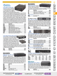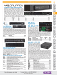
1
DAC LIMITED
ELECTRICAL INSTALLATION
External Bell
All bells must be approved for connection to the telephone netwrk. They
are of the low frequency A.C. ~pe (15Hz-25Hz). D.C. versions must NOT
be used. Connect to terminals 2 and 4 of the tag block. Ensure that DIP
switch SW18 3 is set to '3 (ON)' enabling the internal bell capacitor if a
master socket is NOT used.
Call Restriction Timeout (used when 'CLEAR' key is not fitted)
If this facility is enabled (SW18 -1 set to 'OFF') then each call will be time
restricted to approximately 1 minute, in one of two ways, set by SW18 - 2.
1. Fixed - (SW18- 2 set to 'OFF') the 1 minute starts from the last press
(and release) of the 'PRESS TO CALL' key or the service required.
2. Auto - (SW18 - 2 set to 'ON') the 1 minute starts from the end the last
incoming tone or speech.
Line Terminal Mode Selections
Summary of mode selectable DIP switches:SW18-1
Timeout enable:
SW18-2
1 minute timeout selection:
SW18-3
Internal Bell capacitor (disabled
when master socket is used)
SW24-1
Loop Dial or DTMF Dial
APPROVED for connection to
telecommunication systems
specified in the instructions for
use subject to the conditions set
out in them
12
Document No 552625
OFF - enable
ON - disable (factory
setting)
OFF - fixed (factory setting)
ON - automatic
ON - enabled
OFF - disabled (factory
setting)
Loop Dial- A (factory
setting)
DTMF- 1
USER GUIDE
FOR RA711/1011, /1012 & /1013
VANDAL RESIST TELEPHONES
DAC Limited
Lomeshaye Business Village,
Turner Road. Nelson. BB9 7DR
Tel: +44(0) 1282 447000
Fax: +44 (0) 845 280 1915
Iss. 6 June 2005
Part No: 552625
Issue 6
1
ELECTRICAL INSTALLATION
CONTENTS
This guide is in two parts. The first part is provided for users of this
instrument and the second part is for the sole use of your approved
telephone installer.
Line Terminal Connections and Selections
DO NOT CONNECT THE LINE TERMINATIONS UNTIL
PROGRAMMING-IS COMPLETE (see page 12).
The number of telephones that can be connected to a direct exchange
line or PBX extension is limited by the ringer equivalence number (REN)
of all the telephones connected, this should not exceed a total value of 4.
The REN value of this telephone is 1. In case of doubt consult your
telephone supplier.
Part 1
Part 2
General
3
The Terminal block mounted at the back of the unit is labelled as follows:-
Approved Facilities
4
Operation
6
1.
2.
Line (B)
Bell mute / extension bell
Installation
8
3.
Not used
4.
5.
Line (A) / extension bell
6.
}
}
plug 431A
External induction loop for Hearing
Aid (3 turns, 1m dia)
7.
0 volt
8.
+9 volt
}
external 9 volt dc supply
For a 2-line installation connect 1 and 4.
Programming of Autodial Keys
Ensure that the telephone is disconnected from the telephone line and
that the 9 volt power supply is connected and switched ON. DO NOT USE
THE FRONT PANEL KEYS. To store telephone, numbers 'behind' the
Autodial proceed as follows
2
11
1. Press 'ON', immediately followed by 'STORE'.
2. Press particular Autodial key to be programmed, 'S0', 'S1' or 'S2'.
These keys are part of the group which include the 'STORE' and
'PAUSE'. Note that 'S0' corresponds to the top (EMERGENCY or
PRESS TO CALL) front panel key, 'S1' to the middle and 'S2' to the
bottom key.
3. Enter digits to be stored, (maximum 24). Include pauses as required
for those exchanges that require you to wait for a second dial tone.
4 No digits will be sent to the telephone line.
5. Finish by pressing 'STORE' again, followed by 'CLEAR' if fitted on the
front panel.
6. Reconnect the telephone to the line in accordance with the Line
Connections shown above.
2
11
ELECTRICAL INSTALLATION
GENERAL
Electrical Connections
The types of telephones covered by this guide are approved in the United
Kingdom under the No. S/3064/3/N/502517 for connection to:
The cables are passed through relevant conduit and connected (in the
case of directly wired situations) to the tag block on the instrument.
The telephone is to be
earthed using the
earthbonding point
provided (see diagram).
If the telephone is situated
within electrified railway
locations, other regulations
regarding earthing of
trackside equipment may
apply e.g. BR specification
No. 1686 (Para 5.2.4).
Connect the 9 volt approved DC power supply, Pt.No. RA1050/1000, to
terminals 7 and 8 and ensure that it is switched ON. The adjacent lamp
will illuminate if connected correctly.
If the external hearing aid induction loop is to be installed, connect to the
terminal block in accordance with the connections below and mount
vertically around the instrument.
For versions /1011 and /1013 the Autodial keys have to be correctly
programmed. The program memory requires power. This is supplied by
the 9 volt power supply; loss of this power for a few minutes after
disconnection will not cause memory loss and not at all if the line
connection is made. It is not necessary to have the line connection in
place during programming.
•
A direct exchange line (i.e. a line exclusive to the meter and not
'shared');
•
To an extension of a direct exchange line;
•
To an extension on certain types of PBX.
They are not suitable for use on party line installations or as extensions to
a pay phone.
Faciltities
RA711/1011:
1 number and 'CLEAR' button
RA711/1012:
2 numbers
RA711/1012/C:
2 numbers and 'CLEAR' button
(optional)
RA711/1013:
3 number
RA71 1/1013/C:
3 numbers and CLEAR, button
(optional)
Optional Extra
Hearing Aid Induction loop
RA1060/1000
10
3
APPROVED FACILITIES
INSTALLATION
This apparatus has been approved for use of the following facilities:-
Wall Surface Installation
1
1. Fix the surface mounting back box to the wall, with cut-out at the
bottom, using size 8
or 10 screws with
rawplugs (4 off).
Loudspeaking (no handset) hands-free operation.
2. Visual indication of 'off-hook' condition (line looped).
3. Audible and visual alarm indication of incoming calls.
4. Installation access using special tools only.
5. External mains to DC power supply (9 volts) supplied with each
instrument, Part No. RA1050/1000.
6. Provision for external induction loop for hearing aid use, Part No.
RA1060/I000.
7. Provision to introduce equivalent 'master socket' bell capacitor for
directly wired applications, set by DIP switch on installation.
8. Provision to connect external extension bell.
9. Provision to enable automatic clear down of call loop, either fixed
timeout or timeout after loss of incoming speech, approximately one
minute. Set by DIP switch on installation,
10. Mounting flush to vertical surface, a back-box is provided utilising
standard 20mm 'knock-outs' for cable access. An optional back-box
for conventional surface (protruding) wall mounting is available
11. Up to three 'Autodial' keys initiate a fixed, pre-programmed, series of
digits (24 digits maximum per key).
12. Selectable Loop Dial or DTMF dialling, set by DIP switch on
installation.
13. Optional 'CLEAR' key on RA711/1012 and RA711/1013 where autocall clear-down is inconvenient
14. With a PBX with or without secondary dial tone.
2. Connect the cabling,
as detailed under
Electrical
Connections, and
then fit to the back
box (as described
under Wall Flush
Installation, item 3).
3. Use any suitable
silicone waterproofing
sealant (such as
Unibond Waterproof
Flexible Frame
Sealant) to seal to the
back box. Leave a
12mm to 13mm (0.5")
gap at the bottom for
drainage.
Top-of-pole Installation
1. Place the top-of-pole mounting
over the top of the pole.
2. Tighten the grubscrews to secure
the mounting.
3. Fix the surface mounting back-box
to the top-of-pole mounting with
the screws provided.
4. Connect the cabling, as detailed
under Electrical Connections, and
then fit to the back-box (as
described under Wall Flush
Installation, item 3).
4
9
INSTALLATION
The following information is provided for use by the approved installer or
telephone network supplier only. The RA711 telephone can be either wall
mounted or top-of-pole mounted. Wall mounting can be surface, flush or
inset into the wall. Various electrical options are available as defined
under the Electrical Connections section. Make sure that these are set
correctly before finally fitting the unit to the back box. Mark the removable
insert with your telephone number, if desired.
Wall Flush Installation
1. Produce hole in wall 285mm high 120mm wide 60mm deep.
2. Use size 8 or 10 screws with rawplugs (4 off) to fix back box into wall,
with cut-out at the bottom
3. Connect the cabling, as detailed under the EIectricaI Connections
section. Use a 4mm socket-head key, through the 4 small holes in the
front plate, to fit the telephone unit to the back-box. Start each screw
by turning several rotations at a time until all 4 screws are secure. To
remove the telephone from the box reverse the procedure.
4. Use any suitable silicone waterproofing sealant (such as Unibond
Waterproof Flexible Frame Sealant) to seal to the wall. Leave a 12mm
to 13mm (0.5") gap at the bottom for drainage.
APPROVED FACILITIES
Any other usage will invalidate the approval of the apparatus if as a result
it then ceases to comply with the standards against which the approval
was granted.
Connection is affected by plugging in to the appropriate line socket. If
your telephone connection is not fitted with new style sockets contact
your approved telephone installer or the telephone network supplier
(using the reply card provided).
If this method of connection is inadequate because, for example, the
telephone is to be mounted outside where new sockets are not intended
to be used, arrange for your telephone network supplier to directly
connect the instrument (using the postcard provided).
The telephone should operate correctly when connected to most
compatible PBXs, including those that use secondary dialling tone.
However, it cannot be guaranteed that the apparatus will operate under
all possible conditions of connection. Any cases of difficulty should be
referred in the first instance to your local supplier of the instrument
The telephone is intended for use when powered by the 9 volt DC mains
unit supplied. Other usage will invalidate any approval given to this
apparatus if as a result it ceases to comply with BS 6301:1989.
This apparatus is intended to be internally accessible for installation
purposes only to authorized personnel and must be installed such that
user access is prevented. Correct fitting and installation are mandatory as
failure to prevent such user access will invalidate any approval given to
this apparatus.
8
5
OPERATION - RA711/1011
OPERATION - RA711/1012 &/1013
To make a call
To make a call
Depress the 'PRESS TO CALL' key, dialling tone will NOT be heard.
Depress the 'Autodial' key for the service required, dialling tone will NOT
be heard.
Dialling takes place automatically, including pauses.
Dialling takes place automatically, including pauses.
At the end of a call press 'CLEAR' or wait one minute for automatic
cancellation of call.
At end of call press 'CLEAR' or wait one minute for automatic cancellation
of call.
To answer a call
To answer a call
Depress the 'PRESS TO CALL' key (this will not initiate dialling whilst the
telephone is being called). At the end of the call press 'CLEAR' or wait
one minute for automatic cancellation of call.
Depress any Autodial key (this will not initiate dialling whilst the telephone
is being called). At end of call press 'CLEAR' or wait one minute for
automatic cancellation of call.
6
7