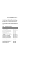
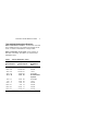
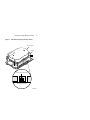
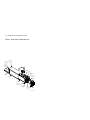
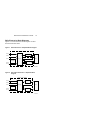
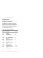
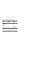
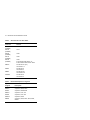
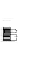
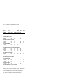
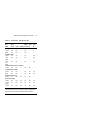
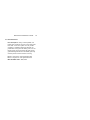
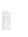
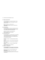
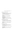
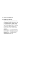
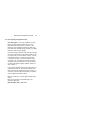
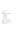
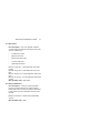
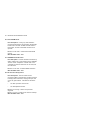
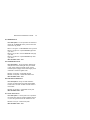
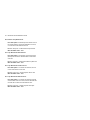
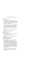
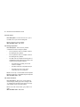
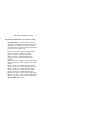
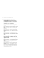
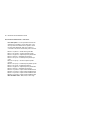
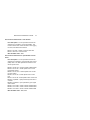
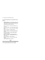
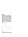
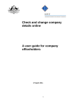
1
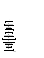
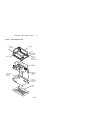
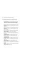
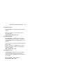
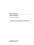
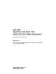
RA7x/SA7x Pocket
Reference Guide
Order Number EK–RSA7X–PG–002
This guide contains quick-reference information for RA7x
disk drives (RA70, RA71, RA72, and RA73) and SA7x
enclosures.
Digital Equipment Corporation
August 1992
The information in this document is subject to change
without notice and should not be construed as a
commitment by Digital Equipment Corporation. Digital
Equipment Corporation assumes no responsibility for any
errors that may appear in this document.
Possession, use, duplication, or dissemination of the
software described in this documentation is authorized
only pursuant to a valid written license from Digital or the
third-party owner of the software copyright.
No responsibility is assumed for the use or reliability of
software on equipment that is not supplied by Digital
Equipment Corporation.
Copyright © Digital Equipment Corporation 1991, 1992
All Rights Reserved.
Printed in U.S.A.
FCC NOTICE: The equipment described in this manual
generates, uses, and may emit radio frequency energy.
The equipment has been type tested and found to comply
with the limits for a Class A computing device pursuant to
Subpart J of Part 15 of FCC Rules, which are designed to
provide reasonable protection against such radio frequency
interference when operated in a commercial environment.
Operation of this equipment in a residential area may cause
interference, in which case the user at his own expense may
be required to take measures to correct the interference.
The following are trademarks of Digital Equipment
Corporation: DEC, DSA, DSDF, HSC, HSC50, HSC70,
KDA, KDA50, KDB50, KDM, MicroVAX, PDP-11, RA, SA,
SDI, UDA, UNIBUS, VAXsimPLUS, and the DIGITAL logo.
Contents
Introduction and Related
Documentation . . . . . . . . . . . . . . .
1
RA7x Characteristics . . . . . . . . . . .
2
Thermal Stabilization Specifications . .
3
Setting Capacity Indicator Switch . . .
4
Troubleshooting . . . . . . . . . . . . . . .
6
RA7x Parts . . . . . . . . . . . . . . . . . .
10
SA7x Parts . . . . . . . . . . . . . . . . . .
13
RA7x Electronics Block Diagrams . . .
15
RA71-RA73 Support . . . . . . . . . . . .
16
RA7x Drive Status Information . . . . .
19
OCP Error Codes . . . . . . . . . . . . . .
30
Drive Error Codes and Fault Numbers
34
iii
iv Contents
Figures
1
RA71/RA72 Capacity Indicator Switch
5
2
Drive Internal Error Log . . . . . . . . . .
7
3
Troubleshooting Flowchart . . . . . . . .
9
4
RA70 Exploded View . . . . . . . . . . .
11
5
RA71-RA73 Exploded View . . . . . . .
12
6
SA7x Enclosure Exploded View . . . .
14
7
RA70 Electronics—Simplified Block
Diagram . . . . . . . . . . . . . . . . . . . .
15
8
RA71-RA73 Electronics—Simplified
Block Diagram . . . . . . . . . . . . . . . .
15
9
RA7x Drive Status . . . . . . . . . . . . .
20
10
RA7x Response Opcode (Byte 1) . . .
21
11
RA7x Lower Unit (Byte 2) and High
Unit and Subunit Mask (Byte 3) . . . .
21
12
RA7x Request Byte (Byte 4) . . . . . . .
22
13
RA7x Mode Byte (Byte 5) . . . . . . . .
23
14
RA7x Error Byte (Byte 6) . . . . . . . . .
24
15
RA7x Controller Byte (Byte 7) and
Retry Count (Byte 8) . . . . . . . . . . . .
25
16
RA7x Previous Command Opcode
(Byte 9) . . . . . . . . . . . . . . . . . . . .
26
17
RA7x Drive State Byte (Byte 10) . . . .
27
18
RA7x Current Cylinder Address (Bytes
11 and 12) . . . . . . . . . . . . . . . . . .
27
19
RA7x Current Group (Byte 13) . . . . .
28
20
RA7x Drive Error Code (Byte 14) . . . .
28
21
RA70 OCP Code Byte; RA71-RA73
Fault Number Byte (Byte 15) . . . . . .
28
22
SA7x OCP . . . . . . . . . . . . . . . . . .
29
Contents v
Tables
1
Related Documentation . . . . . . . . . .
1
2
RA7x Characteristics . . . . . . . . . . .
2
3
Thermal Stabilization Times . . . . . . .
3
4
RA7x Part Numbers . . . . . . . . . . . .
10
5
SA7x Part Numbers . . . . . . . . . . . .
13
6
VAX Diagnostics for RA71-RA73 . . . .
16
7
Operating Systems for RA71-RA73 . .
17
8
SDI Controllers for RA71-RA73 . . . . .
18
9
Retired VAX Supervisor Programs . . .
18
10
OCP Error Codes . . . . . . . . . . . . . .
30
RA7x/SA7x Pocket Reference Guide
1
Introduction and Related Documentation
This guide contains quick-reference information for RA7x
disk drives (RA70, RA71, RA72, and RA73) and SA7x
enclosures.
For more complete information about RA7x disk drives and
SA7x enclosures, see the related documentation listed in
Table 1.
Table 1
Related Documentation
Document Title
RA70 Disk Drive Technical
Description Manual
DSA Troubleshooting Flowchart
BA27 Field Maintenance Print Set
SA7x Support Print Set
SA7x Field Maintenance Print Set
SAxxx Storage Array Configuration
Guide
SA7x Enclosure User Guide
SA7x Enclosure Service Manual
RA7x Disk Drive Service Manual
RA70 Field Maintenance Print Set
RA71/RA72 Support Print Set
RA71/RA72 Field Maintenance Print
Set
RA73 Field Maintenance Print Set
RA73 Support Print Set
Order number
EK–ORA70–TD
EK–DSATF–TM
MP–01429
EM–01435
MP–01435
EK–SAXXX-CG
EK–OSA7X–UG
EK–OSA7X-SM
EK–ORA7X-SM
MP–01428
EM–01434
MP–01434
MP–01439
EM–01439
2 RA7x/SA7x Pocket Reference Guide
RA7x Characteristics
Table 2 lists the characteristics of RA70 and RA71-RA73
disk drives.
Table 2
RA7x Characteristics
Characteristics
RA70
Total Number of Heads
12
RA71
RA72
RA73
15
21
22
14
20
21
1
1
Number of Data Heads
11
Number of Dedicated Servo Heads
1
1
Surfaces Containing Data and Embedded Servo
Information
11
14
20
21
1.0
GB
2.0
GB
Formatted Data Storage Capacity
280
MB
700
MB
Although RA70 and RA71-RA73 disk drives are very similar
in appearance, they differ structurally and electronically.
The RA70 shoe plate is not interchangeable with those for
the RA71-RA73 disk drives. None of the RA7x HDAs or
ECMs are interchangeable.
RA7x/SA7x Pocket Reference Guide
3
Thermal Stabilization Specifications
When condensation is visible on the enclosure or the disk
drive, stabilize the unit in the operating environment for six
hours, or until the condensation is no longer visible.
When condensation is not visible on the enclosure or
disk drive or enclosure, see Table 3 for correct thermal
stabilization times.
Table 3
Thermal Stabilization Times
Temperature
Range Degrees
C
Temperature
Range Degrees
F
Minimum
Stabilization
Time
3 hours
2 hours
1 hour
30 minutes
No stabilization
required
30 minutes
1 hour
2 hours
3 hours
4 hours
5 hours
60
50
40
30
18
to
to
to
to
to
66
59
49
39
29
140
122
104
86
65
to 151
to 139
to 121
to 103
to 85
10
0
–10
–20
–30
–40
to
to
to
to
to
to
17
9
–1
–11
–21
–31
50
32
14
–4
–22
–40
to
to
to
to
to
to
64
49
31
13
–5
–21
4 RA7x/SA7x Pocket Reference Guide
Setting Capacity Indicator Switch
Set the Capacity Indicator switch on the RA71 and RA72
disk drives, shown in Figure 1, as follows:
NOTE
The capacity indicator switch has no function on an
RA73.
•
RA71 (700 MB)
Capacity Indicator switch should be up (on).
•
RA72 (1 GB)
Capacity Indicator switch should be down (off).
RA7x/SA7x Pocket Reference Guide
Figure 1
5
RA71/RA72 Capacity Indicator Switch
TOP COVER HDA
CHASSIS
CAPACITY INDICATOR SWITCH
UNIT SELECT SWITCHES
COM-R002
6 RA7x/SA7x Pocket Reference Guide
Troubleshooting
This section includes troubleshooting tips, an example of
a drive internal error log (Figure 2), and a troubleshooting
flowchart (Figure 3).
Tips for DSA Troubleshooting
Observe the following tips when troubleshooting DSA
products:
•
Avoid formatting new HDA units.
•
Note that EDC errors are not drive problems.
•
Note that forced errors are not necessarily HDA
problems.
•
Avoid running standalone diagnostics unless drive
or system error logs are unavailable and all other
troubleshooting techniques have failed.
•
Ensure that equipment is thermally stabilized before
attempting to power up.
•
Use proper ESD grounding methods. Equipment is
highly susceptible to static damage.
•
Adhere to the service delivery strategy as outlined in
specific component service manuals.
RA7x/SA7x Pocket Reference Guide
Figure 2
7
Drive Internal Error Log
Error Log Entries for Drive 0
(D) = decimal, (A) = ASCII, (H) = hex
Select starting entry location [(7), 1-191] ? 8
Enter how many error log entries to display [(191), 0-191] ? 30
Pause and prompt after every 10 error log entries [(Y), N] ? Y
Drive
Type
Max#Entries
(D)
RA70
Entry
Loctn
(D)
8
7
6
5
4
3
2
1
191
Seeks/Power-on Cum. Seeks Cum. Power-on
(D)
(D)
(D)
191
580
Entry Err
Count Typ
(A)
(D)
2
3
3
3
3
3
3
3
2
DE
DE
DE
Err
Code
(H)
00
39
E7
E9
00
00
00
00
00
1
Seek
Count
(D)
0
453122
452446
452446
451699
451699
451616
451616
0
125000
MFG
Code
(H)
00
32
33
34
00
00
00
00
00
2
00
00
00
00
00
00
00
00
00
00001C20
7200
Drive-Specific Hex
Byte 0-9, right to
(H)
00 00 00 00 00 00
00 09 0A 00 00 00
00 09 04 FF FB 0B
00 09 03 FF FB 0B
00 09 02 02 F6 05
00 09 01 02 F6 05
00 09 00 00 00 00
00 09 00 00 00 00
00 00 00 00 00 00
3
Minutes
(H)
4
Data
left
00
04
05
05
04
04
00
00
00
00
32
42
12
79
7A
42
40
00
00
58
75
9D
A0
BB
A0
C0
00
5 6 7 8
Drive Err
Message
(A)
passed.test
wrg&off.trk
inc.lhd.sek
exp.sek.tmr
drv.sys.ini
exp.onl.atn
drv.sys.ini
drv.pwr.rst
passed.test
9
1. Drive error code—see “Drive error codes and fault numbers” in this guide for an explanation of
these codes
2. Manufacturing code (OCP code)—see the OCP error codes table in this guide for an explanation of these codes
3. Logic Processor Number of Minutes (bytes 9, 8, 7, and 6)
4. Servo Processor Destination Cylinder (bytes 5 and 4)
5. Servo Processor Destination Logical Head Number (byte 3)
6. Servo Processor Physical State Number (byte 2)—see the following page for a list of physical
state numbers
7. Logic Processor Logical State Bit Flags (byte 1)—see the following page for a list of logical
state bit numbers
8. Logic Processor Fault Number (byte 0)
9. Drive error message—see "Drive error codes and fault numbers" in this guide for a translation
of these error messages
COM-0211
8 RA7x/SA7x Pocket Reference Guide
Servo Processor Physical State Numbers (Byte 2)
00–reset
01–retract (unload heads)
02–spin-up motor
03–spin-down motor
04–detent (track follow)
05–seek to cylinder
06–return to cylinder zero (load heads)
07–recalibrate
08–diagnostic
The following State Numbers apply only to the
RA73:
09–fault
0A–PLL lock
Logic Processor Logical State Bit Flags (Byte 1)
Bit
Bit
Bit
Bit
Bit
Bit
Bit
Bit
07–hard error
06–soft fault
05–internal read/write ready
04–drive timing enabled
03–logical attention
02–logical topology state
01–logical available state
00–logical available state
NOTE
For more information about the physical state numbers
and logical state bit flags, see the RA7x Disk Drive
Service Manual.
RA7x/SA7x Pocket Reference Guide
Figure 3
Troubleshooting Flowchart
Talk to the system operator.
Check the OCP for fault indications.
Run VAXsimPLUS.
Analyze the HSC Console Log.
Analyze the Host Error Log.
Analyze the Drive Internal Error Log.
Correlate error codes to the probable failing FRU.
Use host-based diagnostics as a last resort.
Identify prime suspect FRU.
Replace failing FRU.
Verify that the drive is operational.
COM-R080
9
10 RA7x/SA7x Pocket Reference Guide
RA7x Parts
Table 4 lists RA7x part numbers. Figures 4 and 5 shows
exploded views for RA70 and RA71-RA73 disk drives.
Table 4
RA7x Part Numbers
Part
Part Number
RA70 Disk Drive
70-22494-01
70-21946-01
70-22474-01
ECM
HDA
Shoe plate
RA71 Disk Drive
54-20826-01
70-28492-01
70-29408-01
ECM
HDA
Shoe plate
RA72 Disk Drive
54-20826-01
70-28492-02
70-29408-01
ECM
HDA
Shoe plate
RA73 Disk Drive
ECM
HDA
Shoe plate
54-21396-01
70-28699-01
70-29408-01
RA7x Disk Drive
Electronically conductive field
service grounding kit
29-11762
RA7x/SA7x Pocket Reference Guide
Figure 4
11
RA70 Exploded View
SHOCK
ISOLATOR
CHASSIS
GROMMET
BUSHING
SCREW
SCREW
FOR SHOE
PLATE
ATTACHMENT
TOP
COVER/HDA
ELECTRONIC
CONTROL
MODULE
BASEPLATE
CORNER
POSTS
MODULE
RETENTION
KEP NUT
SHOE
PLATE
COM-R004
12 RA7x/SA7x Pocket Reference Guide
Figure 5
RA71-RA73 Exploded View
HDA
ASSEMBLY
SHOCK
ISOLATOR
CHASSIS
ECM
SHOE
PLATE
CXO-3519A-MC_R
RA7x/SA7x Pocket Reference Guide
13
SA7x Parts
Table 5 contains a list of part numbers. Figure 6 shows an
exploded view of an SA7x enclosure.
Table 5
SA7x Part Numbers
Part
Part Number
Chassis (enclosure assembly)
Drive position filler
Fan assembly
Frame assembly
OCP
assembly
cable, long 80 cm (31.5 in)
cable, short 35.6 cm (14 in)
Power cord
Power harness
Power supply
Pushbutton switch
with green LED
Pushbutton switch cap
left front
left rear
right front
right rear
SDI Cables
External cable assembly
Internal cable assembly
Internal SDI cable harness
Transition board
Board 1
Board 2
Transition interface cables
70-23901-01
70-23970-01
70-24440-01
70-23913-01
70-25696-01
70-26254-02
70-26254-01
17-00442-19
70-26255-01
H7869-AK
12-12717-13
12-14027-14
12-14027-15
12-14027-13
12-14027-12
70-26257-01
70-26256-01
17-01699-01
54-19171-01
54-19015-01
17-02147-01
14 RA7x/SA7x Pocket Reference Guide
Figure 6
LEFT REAR
DISK DRIVE
POSITION
SA7x Enclosure Exploded View
RIGHT REAR
DISK DRIVE
POSITION
REAR
COVER
(NOT
SHOWN)
FAN
TRANSITION
BOARD 2
TRANSITION
BOARD 1
OPERATOR
CONTROL
PANEL
POWER
SUPPLY
RA70 DISK
DRIVE SHOWN
CHASSIS
MOUNTING
SCREWS
FRAME
DRIVE POWER
SWITCH PANEL
LEFT FRONT
DISK DRIVE
POSITION
RIGHT FRONT
DISK DRIVE
POSITION
FRONT
COVER
CXO-1845D_S_R
RA7x/SA7x Pocket Reference Guide
15
RA7x Electronics Block Diagrams
Figures 7 and 8 are electronics block diagrams for RA70
and RA71-RA73 disk drives.
Figure 7
RA70 Electronics—Simplified Block Diagram
Logic Read/Write Module
Power J4
Read/Write
Port B J2
Port A J1
I/O Logic
HDA
Local OCP
Servo/Spindle
Remote
OCP J3
Servo/Spindle Module
COM-R082
Figure 8
RA71-RA73 Electronics—Simplified Block
Diagram
Electronic Control Module
Power J4
Read/Write
Port B J2
Port A J1
I/O Logic
HDA
Local OCP
Remote
OCP J3
Servo/Spindle
COM-R081
16 RA7x/SA7x Pocket Reference Guide
RA71-RA73 Support
Tables 6, 7, and 8 list the minimum versions of operating
systems, diagnostics, and SDI controllers that support
RA71-RA73 disk drives in Release 43.
The diagnostics and VAX supervisor programs in Table 6
all recognize RA71-RA73 disk drives. The retired VAX
Supervisor programs in Table 9 do not recognize RA71RA73 disks drives. However, they will properly test and
operate the RA71-RA73 disk drives with the above disk
drive diagnostics when the disk drives are "attached as
RA70 disk drives" during program setup.
Table 6
VAX Diagnostics for RA71-RA73
Diagnostic
Supervisor
EVRAE
EVRLB
EVRLF
EVRLG
EVRLJ
EVRLK
EVRLL
EVRLM
EVRLN
EBSAA
ELSAA
EMSAA
ERSAA
EVSBA
EVSBB
Description
Version
Generic MSCP Exerciser
UDA/KDB50 Basic Disk
Formatter
UDA/KDB50 Basic
Subsystem Diagnostic
UDA/KDB50 Disk Drive
Exerciser
VAX UDA/KDB50/KDM70
Exerciser
VAX Bad Block Replace
Utility
VAX Disk Resident Error
Log Utility
KDM70 EEPROM Update
Utility
DUP Control Program
Supervisor, 8200, 8250,
8300, 8550 (Bereta)
Supervisor, 5800, 6000-2xx,
6000-3xx
Supervisor, 6000-5xx
Supervisor, 6000-4xx
VAX Diagnostic Autosizer
VAX Online Autosizer
4.3
8.3
10.4
10.3
4.3
4.3
3.3
1.6
1.6
14.4-PAT1
14.4-PAT1
14.4-PT1
14.4-PAT1
7.5
4.0
RA7x/SA7x Pocket Reference Guide
Table 7
Operating Systems for RA71-RA73
Operating
Systems
Software
RA71/RA72
Minimum
Version
RA73
Minimum
Version
VMS
VAXsimPLUS
ULTRIX-32
VAXELN
VAX System V
5.4-21
1.6
4.2
4.3
3.2.1
5.5-2
2.0
4.3
4.3-x
Not planned
1 The
Error Log Formatter (ERF) Version 5.4-2 must be
upgraded to Version 5.4-2 (0001) to support RA71-RA72.
Version 5.5-2 is required to support the RA73 disk drive.
17
18 RA7x/SA7x Pocket Reference Guide
Table 8
SDI Controllers for RA71-RA73
SDI
Controller
Minimum
Version
HSC40
(CRONIC)
HSC50
(CRONIC)
HSC60
(CRONIC)
HSC70
(CRONIC)
HSC90
(CRONIC)
V600
V410
V600
V600
V600
K.SI Interface SW Version 12
K.SDI Interface SW Version 39/40
SW Version 30 (3.0)
HW Version 17
SW Version 8
HW Version 4
SW Version 20
HW Version 28
SW Version 6
HW Version 0
KDM70
KDA50
KDB50
UDA50A
Table 9
Retired VAX Supervisor Programs
Supervisor
Program
ECSAA
EDSAA
EJSAA
ENSAA
ESSAA
EWSAA
EBSAA
Description
Supervisor,
Supervisor,
Supervisor,
Supervisor,
Supervisor,
Supervisor,
Supervisor,
8820N
750
8600, 8650
8820/30/40
725, 730
780, 785
9000
8530, 8550, 8700, 8800,
RA7x/SA7x Pocket Reference Guide
19
RA7x Drive Status Information
Figures 9 through 22 disk drive status information diagrams
for the RA7x disk drives. These drives format the drive
status bytes as shown in Figure 9. Note that Byte 15
contains different data for RA70 and RA71-RA73 disk
drives. Byte 15 contains the OCP code for an RA70 disk
drive; for RA71-RA73 drives, byte 15 contains the fault
number.
NOTE
Unless specifically stated otherwise, the status
information diagrams apply to the same bytes for all
RA7x drives.
20 RA7x/SA7x Pocket Reference Guide
Figure 9
RA7x Drive Status
MSB
LSB
RESPONSE CODE
BYTE 1
UNIT NO.
BYTE 2
BYTE 3
SUBUNIT MASK
BYTE 4
OA RR DR SR EL
BYTE 5
W4 W3 W2 W1 DD FO DB S7
MODE BYTE
BYTE 6
DE RE PE DF WE
ERROR BYTE
BYTE 7
S4
BYTE 8
BYTE 9
S3
S2 S1
HI UNIT NO.
C1
PS RU
C2 C3 C4
GENERIC
STATUS BITS
CONTROLLER BYTE
RETRY COUNT
PREVIOUS COMMAND CODE
BYTE 10
DRIVE STATE
BYTE 11
LOW CYLINDER ADDRESS
BYTE 12
HIGH CYLINDER ADDRESS
BYTE 13
REQUEST BYTE
SEEK AND RECALL
EXTENDED DRIVE
STATUS BYTES
CURRENT GROUP
BYTE 14
DRIVE ERROR CODE
BYTE 15
SEE NOTE
NOTE: IF DRIVE IS RA70, BYTE 15 CONTAINS OCP CODE. IF DRIVE IS
RA71/RA72/RA73, BYTE 15 CONTAINS FAULT NUMBER.
CXO-3521A-TI_R
RA7x/SA7x Pocket Reference Guide
Figure 10
21
RA7x Response Opcode (Byte 1)
X X X X
X X X X
Byte 1 — Response Opcode
COM-R055
Figure 11
RA7x Lower Unit (Byte 2) and High Unit and
Subunit Mask (Byte 3)
Byte 3
0 0 0 1
X X X X
Byte 2
X X X X
X X X X
Drive select unit number
Subunit 0 mask (subunit 0 reporting this status)
Subunit 1 mask (not used)
Subunit 2 mask (not used)
Subunit 3 mask (not used)
COM-R056
22 RA7x/SA7x Pocket Reference Guide
Figure 12
X X X X
RA7x Request Byte (Byte 4)
X X X X
Byte 4
Request Byte
(RU) 0 = Run/Stop switch out
1 = Run/Stop switch in
(PS) 0 = Port switch out
1 = Port switch in
(PB) 0 = Port A receivers enabled
1 = Port B receivers enabled
(EL) 0 = No loggable information in extended status area
1 = Loggable information in extended status area
(SR) 0 = Spindle not ready (not up to speed)
1 = Spindle ready
(DR) 0 = No diagnostic is being requested from the host
1 = There is a request for a diagnostic to be loaded into
the drive microprocessor memory
(RR) 0 = Drive requires no recalibrated command
1 = Drive request recalibrated command
(OA) 0 = Drive on-line or available to current controller
1 = Drive unavailable (it is already on-line to another
controller)
COM-R057
RA7x/SA7x Pocket Reference Guide
Figure 13
X X 0 X
23
RA7x Mode Byte (Byte 5)
X X X X
Byte 5
Mode Byte
(S7) 0 = 512-Byte sector format (16 bit)
1 = 576-Byte sector format (18 bit)
(no current plan to implement 18 bit)
(DB) 0 = DBN area access disabled
1 = DBN area access enabled
(FO) 0 = Formatting operations disabled
1 = Formatting operations enabled
(DD) 0 =Drive enabled by controller error routine or diagnostic
1 = Drive disabled by controller error routine or diagnostic
(Fault Light = ON)
(W1) 0 = Write Protect switch for subunit 0 is out
1 = Write Protect switch for subunit 0 is ON
(W2) Not implemented
(ED1) Error log disable (set by 2-board controller diagnostics)
(ED0) Error log disable (set by 2-board controller diagnostics)
COM-R058
24 RA7x/SA7x Pocket Reference Guide
Figure 14
X X X X
RA7x Error Byte (Byte 6)
X 0 0 0
Byte 6
Error Byte
(WE) 0 = No error
1 = Write lock error (attempt to write while
write protected)
(DF) 0 = No error
1 = Drive failure during initialization
(PE) 0 = No error
1 = Level 2 protocol error (improper command
codes or parameters issued to drive)
(RE) 0 = No error
1 = SDI receive error on SDI transmission
line(s) from controller
(DE) 0 = No error
1 = Drive error (drive Fault light may be on
—possibly clearable via DRIVE CLEAR
command)
COM-R059
RA7x/SA7x Pocket Reference Guide
Figure 15
0 0 0 1
25
RA7x Controller Byte (Byte 7) and Retry
Count (Byte 8)
X X X X
Byte 7
Controller Byte
0000 = Normal drive operation
1000 = Drive off-line (under control of a diagnostic)
1001 = Drive off-line (another drive has same unit select
identifier)
(S1) 1 (not used)
(S2) 1 (not used)
(S3) 1 (not used)
(S4) 1 (not used)
X X X X
X X X X
Byte 8
Retry Count/Failure Code
COM-R060
26 RA7x/SA7x Pocket Reference Guide
Figure 16
RA7x Previous Command Opcode (Byte 9)
X X X X X X X X
Byte 9
Last Opcode
(Extended drive status byte)
Opcode of the last previous level 2 drive command
decoded by the drive (received from the SDI controller)
COM-R061
Last Level 2 Drive Commands
The following is a list of the last level 2 drive commands
decoded by the drive (received from the SDI controller).
81—change mode
82—change controller flags
03—diagnose
84—disconnect (drive)
05—drive clear
06—error recovery
87—get common characteristics
88—get subunit characteristics
0A—initiate seek
8B—on line
0C—run
8D—read memory
8E—recalibrate
90—topology
0F—write memory
FF—select group (level 1 command, processed by
firmware seek head select subroutines)
RA7x/SA7x Pocket Reference Guide
Figure 17
X X X X
27
RA7x Drive State Byte (Byte 10)
X X X X
Drive State Bit Flags
Byte 10
Contains a number representing state
of drive at time of error
AV 1 = Available asserted
OL 1 = Drive in on-line status
TP 1 = Drive executing level 2 topology command
AT 1 = Attention asserted
TG 1 = Sector + index timing enabled for transmission
via RTDS line
RW 1 = Drive is internal read/write ready
SF 1 = Soft fault detected; possibly clearable via
level 2 clear command
HE 1 = Hard error; drive must be power-cycled to attempt
to clear this error
COM-R062
Figure 18
RA7x Current Cylinder Address (Bytes 11
and 12)
Byte 12
X X X X
X X X X
Byte 11
X X X X
X X X X
Cylinder requested during last seek command
COM-R063
28 RA7x/SA7x Pocket Reference Guide
Figure 19
RA7x Current Group (Byte 13)
X X X X
X X X X
Byte 13
Group number currently selected
(will be read/write head number in
an RA7x)
COM-R064
Figure 20
RA7x Drive Error Code (Byte 14)
X X X X
X X X X
Byte 14
Drive Error Code
COM-R065
Figure 21
X X X X
RA70 OCP Code Byte; RA71-RA73 Fault
Number Byte (Byte 15)
X X X X
Byte 15
OCP/fault number code indicates to
module repair centers (as close as
possible) area of logic specifically in
question
COM-R066
RA7x/SA7x Pocket Reference Guide
Figure 22
29
SA7x OCP
PORT SWITCHES
LEFT
REAR
d i g i t a l
Run
Fault
Unit No.
/Set No. Ready
Write A
Protect
B
O
O
O
000
O
O
O
O
O
O
002
O
O
O
LEFT
FRONT
PORT SWITCHES
Unit Select
Run
Fault
Unit No.
/Set No. Ready
Write A
Protect
RIGHT
REAR
B
O
O
O
001
O
O
O
O
O
O
003
O
O
O
RIGHT
FRONT
SERIAL NO.
LABEL FOR
RIGHT REAR
DISK POSITION
SERIAL NO.
LABEL FOR
RIGHT FRONT
DISK POSITION
SERIAL NO.
LABEL FOR
LEFT REAR
DISK POSITION
FRONT
COVER
PC DRIVE
POWER SWITCHES
SERIAL NO.
LABEL FOR
LEFT FRONT
DISK POSITION
LEFT
FRONT
LEFT
REAR
RIGHT
REAR
RIGHT
FRONT
COM-0204
30 RA7x/SA7x Pocket Reference Guide
OCP Error Codes
Table 10 lists the error codes displayed by the OCP lights.
The next section, "Drive Error Codes and Fault Numbers,"
describes each error code and the most probable cause of
the error.
Table 10
OCP Error Codes
Description
and
Run
FRUs
Stop
Fault
Write Port
Ready Protect A
00–No error
–
–
–
01–Logic input/output module
Note1
–
–
–
02–SDI PSID interface
ECM
–
–
–
–
–
–
SDI
controller
SDI
–
–
–
cable
03–SDI gate array
ECM
–
–
–
04–MC 6803 microcomputer
ECM
–
–
–
05–27264 UVPROM
ECM
–
–
–
06–2716 static RAM
ECM
–
–
–
07–X2816A EEPROM
ECM
–
–
–
08–Bus decoders and drivers
Note1
–
–
On
09–ZXENDEC
ECM
–
–
On
Port
B
–
–
–
–
–
On
–
–
On
On
–
–
–
On
–
–
On
On
On
–
–
On
–
On
On
On
–
On
On
On
–
–
–
–
–
On
1 Obtain the drive error code from the host error log, the
internal drive error log, or the HSC console. Refer to the
next section "Drive Error Codes and Fault Numbers."
RA7x/SA7x Pocket Reference Guide
Table 10 (Continued)
Description
and
Run
FRUs
Stop
Fault
31
OCP Error Codes
Write Port
Ready Protect A
SDI
–
–
On
–
controller
0A–Analog signal processor
ECM
–
–
On
–
HDA
–
–
On
–
0B–Detector qualifier
Note1
–
–
On
–
11–Servo module digital circuits
ECM
–
On
–
–
HDA
–
On
–
–
12–Servo gate array
ECM
–
On
–
–
13–TMS 32020 processor
ECM
–
On
–
–
14–Static RAM
ECM
–
On
–
On
15–Servo analog
ECM
–
On
–
On
HDA
–
On
–
On
16–Voltage controlled oscillator (VCOO)
ECM
–
On
–
On
HDA
–
On
–
On
17–Spindle motor control chip
ECM
–
On
–
On
HDA
–
On
–
On
18–Spindle power amp
ECM
–
On
On
–
HDA
–
On
On
–
19–Actuator power amp
Port
B
–
On
On
On
–
–
On
On
–
–
On
On
On
–
On
On
–
–
–
–
On
On
On
On
–
–
On
On
On
On
–
–
–
–
1 Obtain the drive error code from the host error log, the
internal drive error log, or the HSC console. Refer to the
next section "Drive Error Codes and Fault Numbers."
32 RA7x/SA7x Pocket Reference Guide
Table 10 (Continued)
Description
and
Run
FRUs
Stop
Fault
OCP Error Codes
Write Port
Ready Protect A
ECM
–
On
On
–
–
HDA
–
On
On
–
–
1A–Actuator analog
ECM
–
On
On
–
On
HDA
–
On
On
–
On
1B–A-D and D-A converters
ECM
–
On
On
–
On
HDA
–
On
On
–
On
1C–Analog MUXs
ECM
–
On
On
On
–
HDA
–
On
On
On
–
1E–HDA Capacity Indicator switch setting
ECM
–
On
On
On
On
HDA
–
On
On
On
On
Note2
–
On
On
On
On
1F–Head/disk assembly
HDA
–
On
On
On
On
ECM
–
On
On
On
On
30–Microprocessor module
ECM
On
On
–
–
–
31–OCP module
ECM
On
On
–
–
–
Note1
On
On
–
–
–
32–Fault module
Note1
On
On
–
–
On
33–Spindle motor control module
Note1
On
On
–
–
On
Port
B
On
On
–
–
On
On
–
–
–
–
–
On
On
–
On
On
–
On
1 Obtain the drive error code from the host error log, the
internal drive error log, or the HSC console. Refer to the
next section "Drive Error Codes and Fault Numbers."
2 Verify that the HDA Capacity Switch setting is as described
in "Setting the Capacitor Indicator Switch" section.
RA7x/SA7x Pocket Reference Guide
Table 10 (Continued)
Description
and
Run
FRUs
Stop
Fault
33
OCP Error Codes
Write Port
Ready Protect A
34–Digital signal processor module
ECM
On
On
–
On
HDA
On
On
–
On
35–SDI module
ECM
On
On
–
On
SDI
On
On
–
On
cable
On
On
–
On
SDI
controller
36–Microprocessor unit module
Note1
On
On
–
On
37–Diagnostic module
ECM
On
On
–
On
HDA
On
On
–
On
3E–Debug error trap
Note1
On
On
On
On
3F–Power supply
ECM
On
On
On
On
Power
On
On
On
On
supply
Note1
On
On
On
On
Port
B
–
–
–
–
–
–
On
On
–
On
On
–
On
On
On
On
On
–
On
On
On
On
On
On
1 Obtain the drive error code from the host error log, the
internal drive error log, or the HSC console. Refer to the
next section "Drive Error Codes and Fault Numbers."
34 RA7x/SA7x Pocket Reference Guide
Drive Error Codes and Fault Numbers
00—Internal Error Log Events
Error Description: The following fault numbers (FNs)
may appear in the drive internal error log with a drive
error code of "00" (not a drive error):
FN: 00—passed.test.—no drive detected fault
FN: 20—drv.sys.rst.—valid drive system reset
FN: 3E—rdg.off.trk.—read gate and off track
The drive will not post a recoverable read-and-off-track
error to prevent interruption to the controller. This
allows the controller to execute all of its available
retry/error recovery sequences to the drive and if
necessary, retrieve user data during a recoverable
error.
FN: A0—drv.sys.ini.—valid drive system initialize.
The drive received an INIT pulse from the controller via
the SDI RTCS line.
FN: BB—exp.onl.atn.—expired on-line timer with
attention.
While in the on-line state, the drive timed out the
controller and raised attention. A second timeout
occurred and the drive performed a disconnect to the
SDI and went to the available state. This is usually the
result of a host failure, a controller failure, or SDI cable
disconnection.
FN: BC—inv.sys.ini.—invalid or spurious SDI INIT.
The drive received a SDI initialize pulse (via RTCS
line) and discontinued the drive clock (per SDI
specification), but the controller did not clear SDI INIT
after the drive responded with discontinued clocks.
FN: C0—drv.pwr.rst.—drive power reset
FN: 28—int.brt.ers.—initiate burst write erase
FN: 29—ini.brt.wrt.—initiate burst write
FN: 2A—passed.brwt.—burst write complete
Most Probable Cause: Refer to specific Fault Number
(FN) above.
03—Spin-Up Timeout
Error Description: The I/O processor has instructed
the spindle subsystem to spin up, but the spindle
subsystem has not indicated up to speed within 15
seconds.
FN: 70—exp.sup.tmr.—expired spinup timer
RA7x/SA7x Pocket Reference Guide
35
FN: 72—exp.pur.tmr.—expired purge cycle timer)
Most Probable Cause: ECM, HDA
04—Spin-Up Actuator Fault
Error Description: Prior to a spinup operation, the
drive firmware performs some actuator tests. A failure
during this test will result in this error and the drive will
abort any further attempts to spin up the disks.
FN: 6F—sup.svo.dgn.—spinup servo diagnostic fault)
Most Probable Cause: HDA, ECM
05—Power Supply
Error Description: The drive has detected changes
in PWR OK resulting from the detection of ACOK or
changes detected by the on board +12v and +5v dc
sensor circuits. This may cause all of the operator
control panel (OCP) indicators to stay on.
FN: 3F—inv.drv.pwr.—invalid or spurious drive power
Most Probable Cause: SA7x Power Supply, Internal
SA7x cables, ECM, site power problems
06—Microcode Fault
Error Description: The I/O processor tried to access
an unused ROM location due to a hardware problem
or a software error internal to the drive.
FN: Not Appropriate
Most Probable Cause: ECM
36 RA7x/SA7x Pocket Reference Guide
07—Frame Sequence Error
Error Description: There are three transmission error
types that are reported as sequence errors:
•
A message continuation frame or message end
frame was decoded before a message start
frame.
•
Two message start frames were decoded in a
row.
•
Less than two frames, a message start frame
and a message end frame, or more than 63
frames have been decoded before a message
end frame.
FN: A1—grp.frm.seq.—group select frame sequence
error
FN: AB—str.frm.seq.—start frame sequence error
FN: AC—con.frm.seq.—continue frame sequence error
FN: AD—end.frm.seq.—end frame sequence error
Most Probable Cause: ECM, SDI controller, SDI
cable
08—Level 2 Message Checksum Error
Error Description: The last level 1 frame transmitted
as a result of a level 2 command is the message end
frame. The lower eight bits of the end frame contain
a checksum for the entire level 2 message. This error
occurs if the checksum calculated by the drive does
not match the checksum transmitted as part of the
message end frame.
FN: A5—inc.cmd.cksm—incorrect command packet
checksum
Most Probable Cause: ECM, SDI controller, SDI
cable
09—SDI Message Framing Error
Error Description: The upper eight bits of the control
frame did not match one of the nine possible framing
codes as defined in the SDI specification.
FN: A4—inv.frm.code.—invalid frame code
Most Probable Cause: ECM, SDI controller, SDI
cable
RA7x/SA7x Pocket Reference Guide
37
0A—SDI Command Opcode Parity Error
Error Description: The opcode in a level 2 SDI
command was received with incorrect parity. The
opcode byte must be even parity.
FN: B3—inc.opc.prty—incorrect command opcode
parity
Most Probable Cause: ECM, SDI controller, SDI
cable
0B—Invalid Opcodes
Error Description: One of two conditions have been
detected:
•
The opcode received in the level 2 command was
not one of the 16 possible opcodes.
•
The opcode received in the level 2 command was
one of the 16 possible opcodes, but the opcode
parity was wrong.
FN: B2—inv.cmd.opcd.—invalid command packet
opcode
FN: B7—inv.lv1.opcd.—invalid level 1 command
opcode
Most Probable Cause: ECM, SDI controller, SDI
cable
0C—Command Length Error
Error Description: The byte count for any given level
2 command is incorrect.
FN: A3—inv.cmd.byct.—invalid command packet byte
count
FN: B1—inv.cmd.byct.—invalid command packet byte
count
FN: B6—inc.lv1.byct.—invalid level 1 command packet
byte count
Most Probable Cause: ECM, SDI controller, SDI
cable
38 RA7x/SA7x Pocket Reference Guide
0E—Real-Time Command Contains Invalid Head
Address
Error Description: A real-time command is one of the
SDI level 1 data transfer commands. If the low byte of
any of these commands indicates an invalid head, this
error occurs.
FN: A2—inv.grp.num.—invalid group select (head)
number
Most Probable Cause: ECM, SDI controller, SDI
cable
13—Spindle Fault
Error Description: The motor control circuit has
detected a condition that could prevent the spindle
from spinning at a safe speed.
FN: 63—ast.smc.flt.—asserted spindle motor control
fault
Most Probable Cause: ECM, HDA
14—Spindle Over Current
Error Description: The current being used by the
spindle motor is too high.
FN: 61—ast.smc.pwr.—asserted spindle motor control
power
FN: 62—neg.smc.pwr.—negated spindle motor control
power
Most Probable Cause: ECM, HDA, SA7x power
supply
RA7x/SA7x Pocket Reference Guide
16—Guard Band Error
Error Description: During normal operation, the
heads have moved into the inner or the outer guard
band area. If the servo system is in the process
of loading or unloading heads (for example: the
positioner is moving from the landing zone or to the
landing zone), the I/O processor will mask out the
guard band signals internal to the GASP gate array
and thus prevent a servo fault from occurring.
FN: 46—out.grd.bnd.—outer guard band fault
FN: 47—inn.grd.bnd.—inner guard band fault
Most Probable Cause: ECM, HDA
39
40 RA7x/SA7x Pocket Reference Guide
17—Invalid or Inconsistent Parameters
Error Description: One or more of the parameters
sent by the controller as part of the level 2 command is
invalid or inconsistent.
FN: 18—inv.gbd.cyl.—invalid guard band cylinder
access
FN: AE—inc.sct.fmt.—incorrect drive sector format
FN: B8—inv.lv1.grp.—invalid level 1 group select
(head) number
FN: C2—inv.sct.fmt.—invalid drive sector format
FN: C3—inv.dmr.num.—invalid diagnose memory
region number
FN: C4—inc.dmr.num.—incorrect diagnose memory
region number
FN: C6—inv.top.disc.—invalid topology disconnect
FN: C7—err.flg.astd.—generic error bit flag asserted
FN: C9—inv.lv1.num.—invalid error recovery level
number
FN: CB—inv.grp.num.—invalid group select (head)
number level 2
FN: CC—inv.cyl.adr.—invalid cylinder address number
level 2
FN: CD—inv.dgn.cyl.—invalid diagnostic cylinder
access
FN: D0—inv.rmr.num.—invalid read memory region
number
FN: D1—inv.rmr.ofst.—invalid read memory region
offset
FN: D3—inv.wmr.byct.—invalid write memory region
byte count
FN: D4—inv.wmr.num.—invalid write memory region
number
FN: D5—inv.wmr.ofst.—invalid write memory region
offset
FN: D6—inv.wmr.siz.—invalid write memory region size
Most Probable Cause: ECM, SDI controller, SDI
cable
RA7x/SA7x Pocket Reference Guide
41
18—Opcode/Parameter Invalid/Inconsistent with Drive
State
Error Description: The level 2 command received
from the controller is valid, but the command itself or
a parameter contained in the command is inconsistent
with the drive’s current state or physical status.
FN: 68—asup.bkd.ctrl.—spinup blocked by the
controller
FN: 69—sup.bkd.dgn.—spinup blocked by diagnostic
FN: B4—inc.cmd.flt.—incorrect command drive fault
state
FN: B5—inc.cmd.lsn.—incorrect command drive logical
state number
FN: B9—inv.svo.hsw.—invalid level 1 servo head
switch
FN: C1—drv.wrt.prtd.—drive write protected
FN: C5—inc.drst.top.—incorrect drive state—NOT
topology
FN: C8—flt.not.negd.—fault or error not cleared
FN: CA—inv.svo.rcv.—invalid servo error recovery
FN: CE—inv.svo.sek.—invalid servo seek
FN: CF—run.sw.stop.—run switch in ’STOP’ position
FN: D2—inv.run.lsn.—invalid run logical state number
Most Probable Cause: ECM, SDI controller, SDI
cable
1D—Actuator Over Speed Error
Error Description: During course positioning mode
the positioner velocity was greater than design
specifications.
FN: 4B—act.ovr.spd.—actuator over speed
Most Probable Cause: ECM, HDA
1E—Actuator Over Current Error
Error Description: The current being used by the
read/write head actuator is too high.
FN: 4C—act.ovr.cur.—actuator over current
Most Probable Cause: ECM, HDA
42 RA7x/SA7x Pocket Reference Guide
1F—Sector Overrun Error
Error Description: The internal read gate or write
gate was asserted and a sector pulse or an index
pulse occurred.
FN: 51—sct.ovr.run.—sector over run
Most Probable Cause: ECM, SDI controller, SDI
cable, HDA
25—Off Track Error
Error Description: During track following mode, the
DSP processor determined that the read/write heads
are not within track center line tolerances.
FN: 4D—svo.off.trk.—servo off track error
Most Probable Cause: HDA, ECM
26—Spindle Speed Error
Error Description: The spindle speed is not operating
within design specifications. The nominal spindle
speed is 4000 r/min for the RA70 and 3600 r/min for
the RA71/RA73 disk drives.
FN: 6E—inc.sup.svo.—incorrect spinup servo state
number
FN: 71—inc.sup.psn.—incorrect spinup physical state
number
FN: 73—inc.pur.psn.—incorrect purge cycle physical
state number
FN: 77—inc.run.psn.—incorrect run physical state
number
Most Probable Cause: ECM, HDA
27—HDA Over Temperature
Error Description: The temperature inside the HDA
has exceeded the maximum allowed for safe operation.
FN: 4F—hda.ovr.tmp.—head disk assembly over
temperature
Most Probable Cause: SA7x fan, HDA, ECM.
Be sure the disk is operating within the environmental
specifications.
RA7x/SA7x Pocket Reference Guide
43
28—Module Over Temperature Error
Error Description: Sensing circuits on the ECM have
detected temperatures that exceed the maximum
allowed for safe and reliable operation.
FN: 4E—snk.ovr.tmp.—heat sink assembly over
temperature
FN: 3C—xep.ovr.tmp.—module exception over
temperature error
FN: 3D—com.ovr.tmp.—module common over
temperature error
Most Probable Cause: SA7x fan, ECM, HDA. Be
sure that the disk is operating within the environmental
specifications.
31—Read Gate and Write Gate Error
Error Description: The SDI gate array detected both
internal read gate and write gate at the same time.
FN: 5A—rdg&wrs.ast.—read state and write state both
asserted
Most Probable Cause: ECM, SDI controller, SDI
cable
32—Read/Write While Faulted
Error Description: Even though the drive is in a
faulted condition, the drive detected either RTCS read
gate or RTCS write gate.
FN: 52—flt&rdg.wrg.—fault and read gate or write gate
both asserted
Most Probable Cause: ECM, SDI controller, SDI
cable
44 RA7x/SA7x Pocket Reference Guide
33—Attempt to Write Through Bursts
Error Description: The read/write heads were over
the embedded burst area of the sector, and the internal
write gate was asserted.
FN: 53—wrg&brt.prt.—write gate and burst protection
both asserted
Most Probable Cause: SDI controller, ECM, SDI
cable
NOTE
See Table 9 and verify the minimum controller revision.
34—Data Encoder/Decoder Error
Error Description: A failure of the data
encoder/decoder custom chip or some of its associated
circuitry.
FN: 5C—enc.pls.flt.—encoder pulse fault (RWENDEC)
Most Probable Cause: ECM
35—Write Unsafe
Error Description: A condition exists with the write
data path (for example: read/write heads, preamp
chips, flex circuit, etc.) which would prevent the drive
from correctly writing data to the disk surface.
FN: 5B—wrg&wrt.uns.—write gate and write unsafe
both asserted
Most Probable Cause: ECM, HDA
39—Write and Off Track
Error Description: While write gate was asserted, the
read/write heads moved off track.
FN: 58—wrg&off.trk.—write gate and off track both
asserted
Most Probable Cause: ECM, HDA
RA7x/SA7x Pocket Reference Guide
45
3A—Write and Write Protected
Error Description: The drive was write protected and
detected the assertion of the internal write gate.
FN: 59—wrg&wrt.prt.—write gate and write protection
both asserted
Most Probable Cause: ECM, SDI controller, SDI
cable
3B—AGC Fault
Error Description: Either the automatic gain control
(AGC) circuit has failed or read signal amplitude
variations have far exceeded the capability of the AGC
circuit to maintain a proper signal lock. The latter of
these may be caused by a severe signal degradation
ratio (SDR, erasure) from a defective HDA.
FN: 5D—agc.lck.flt.—automatic gain control lock fault
Most Probable Cause: ECM, HDA
3C—Servo Faults
Error Description: There are hardware-detected
inconsistencies with the servo system. These are
divided into two categories: actuator faults and servo
faults.
FN: 57—hrd.svo.flt.—hard servo fault
Most Probable Cause: ECM, HDA
41—SDI Command/Response Timeout
Error Description: The drive detected the start of an
incoming SDI command or the transmission of an SDI
response, but the operation did not complete within a
specified time period.
FN: A8—exp.rsp.tmr.—expired response packet timer
FN: A9—exp.cmd.tmr.—expired command packet timer
Most Probable Cause: ECM, SDI controller, SDI
cable
46 RA7x/SA7x Pocket Reference Guide
43—TCR and R/W Ready Out L
Error Description: Transfer command received (TCR)
and read/write ready out L indicates the drive received
a data transfer command and read/write ready was not
asserted.
FN: 50—tcr&r/w.rdy.—TCR and NOT read/write ready
both asserted
Most Probable Cause: ECM, SDI controller, SDI
cable
44—Format Command and Format Not Enabled
Error Description: An SDI level 1 select track and
format on index or format on sector or index command
was decoded by the SDI gate array, but the enable
format bit was not set.
FN: 55—fmt.w/o.ena.—format command without format
enabled error
Most Probable Cause: ECM, SDI controller, SDI
cable
4B—Index Error
Error Description: Index was detected when it should
not have been or was not detected when it should
have been.
FN: 56—idx.pls.flt.—index pulse fault
Most Probable Cause: HDA, ECM
4C—External Hardware Fault
Error Description: The gate array or the ground
connection on the ECM is broken.
FN: 5E—ext.hrd.flt.—external hardware fault
Most Probable Cause: ECM
RA7x/SA7x Pocket Reference Guide
47
4D—Write and Bad Embedded
Error Description: The drive internal write gate is
asserted and embedded bursts are not valid.
FN: 54—wrg&emb.bad.—write gate and embedded
NOT OK both asserted
Most Probable Cause: ECM, HDA
4F—SDI Transmit Error—Pulse Error
Error Description: Extra or missing pulses on the SDI
write command line (data pulse error) or the RTCS line
(control pulse error) were detected.
FN: 5F—tcr&pls.err.—TCR and pulse error both
asserted (PSID)
Most Probable Cause: ECM, SDI controller, SDI
cable
50—DSP Diagnostic Timeout
Error Description: There is not a specific error code
for a failure during the initialization section of the DSP
diagnostic. However, if the DSP fails to execute the
basic initialization, it is most likely hung (or lost) and
is not able to pass an error code to the I/O processor.
It is possible that the initialization completed and the
problem is with the analog loop test. Realize that the
effect is the same: the I/O processor detects diagnostic
timeout due to the fact the DSP does not respond with
diagnostic complete or error detected.
FN: 84—exp.exc.tmr.—expired servo (DSP) execute
timer
Most Probable Cause: ECM
51—Byte/Sector Counter Failure
Error Description: Reported any time the counter is
checked and is incorrect.
FN: E5—inv.sct.ctr.—invalid sector counter
Most Probable Cause: ECM
48 RA7x/SA7x Pocket Reference Guide
60—Read/Write Head Select Failure
Error Description: One of two conditions occurred.
While trying to select a specific head to read or write,
the DSP detected a soft servo fault and as such could
not complete the head switch operation, or the I/O
processor timed out waiting for the DSP to complete
the head switch operation. Realize that if the drive
detects any other faults, these faults are reported with
the real-time error code associated with the error.
FN: F2—inv.dgn.cnt.—invalid diagnostic (head) bit
error count
FN: F3—inc.dgn.cnt.—incorrect diagnostic (track) bit
error count
FN: F5—exp.dgn.sct.—expired diagnostic sector timer
FN: FA—exp.dgn.rws.—expired diagnostic read/write
sector timer
FN: FE—inc.dgn.rdy.—incorrect diagnostic ready
Most Probable Cause: ECM, HDA
RA7x/SA7x Pocket Reference Guide
49
61—Drive Capacity Configuration Error
Error Description: One of two conditions occurred.
Either the HDA capacity indicator switch on the
RA71/RA72 disk drive was set incorrectly, or the
ECM logic cannot determine whether the HDA is an
RA71 disk drive (700 MB storage capacity) or an RA72
disk drive (1 GB storage capacity).
If the HDA capacity indicator switch was set incorrectly,
the drive will spin down and you will be unable to spin
it up again until you set the switch correctly. You will
receive fault number 19. Verify the switch setting.
If the HDA is an RA71, the switch should be in the
on position (up). If the HDA is an RA72, the switch
should be in the off position (down). See the section
on setting RA71/RA72 capacity indicator switch and
refer to Figure 1.
If the capacity indicator switch is set correctly and you
obtain fault number 1A, this indicates that the head
table, which defines whether the drive is an RA71 or
an RA72, cannot be read from the HDA. The problem
may be related to the ECM or HDA.
FN: 19—inc.hda.swi.—incorrect HDA capacity switch
setting
FN: 1A—inv.hda.type—invalid HDA type (can’t
determine HDA type)
Most Probable Cause: ECM, HDA
50 RA7x/SA7x Pocket Reference Guide
62—Read Failure
Error Description: One of six possible conditions
occurred during the diagnostic read section of the test.
The six conditions are:
•
Invalid sector number
•
Expired sector timer
•
Expired read sector timer
•
Incorrect read sector
•
Read diagnostic failure
•
Incorrect sector error count
FN: F4—inv.dgn.sct.—invalid diagnostic read sector
number
FN: F6—inv.dgn.rsf.—invalid diagnostic read sector
fault
FN: F7—exp.dgn.rds.—expired diagnostic read sector
timer
FN: F8—inc.dgn.rds.—incorrect diagnostic read sector
number
Most Probable Cause: ECM, HDA
RA7x/SA7x Pocket Reference Guide
51
67—Write Failure
Error Description: One of five possible conditions
occurred during the diagnostic write section of the test.
The five conditions are:
•
Invalid sector number
•
Expired sector timer
•
Expired write sector timer
•
Incorrect write sector
•
Write diagnostic failure
FN: F9—inv.dgn.wsn.—invalid diagnostic write sector
number
FN: FB—inv.dgn.wsf.—invalid diagnostic write sector
fault
FN: FC—exp.dgn.wrs.—expired diagnostic write sector
timer
FN: FD—inc.dgn.wrs.—incorrect diagnostic write sector
number
Most Probable Cause: ECM, HDA
85—External RAM Failure
Error Description: If, during any data verification
process, the data stored in the processor external
RAM location does not match the data that was written
to that location, the test is terminated and this error is
reported.
FN: E3—inv.dat.mem.—invalid external static RAM
memory
Most Probable Cause: ECM
52 RA7x/SA7x Pocket Reference Guide
86—Internal RAM Failure
Error Description: If during any data verification
process the data stored in the processor internal RAM
location does not match the data that was written to
that location, the test is terminated and this error is
reported.
FN: E4—inv.ram.mem.—invalid internal static RAM
memory
Most Probable Cause: ECM
87—UVPROM Checksum Failure
Error Description: This test calculates a checksum by
adding, without carry, all the locations of the UVPROM.
The sum is then compared to a stored value. If the
computed sum and the stored sum do not match, this
error will result.
FN: E2—inv.rom.sum.—invalid UVPROM checksum
Most Probable Cause: ECM
88—I/O Processor Sanity Failure
Error Description: This test verifies the I/O
processor’s ability to execute basic processor functions
including branch instructions, verifying interrupts, and
one of the general timers. Indications of this failure
are:
•
The basic processor functions fail.
•
The interrupt/timer test fails.
FN: E0—ins.mcu.dgn.—insane microprocessor
diagnostic
FN: E1—inv.ctr.int.—invalid counter over flow interrupt
Most Probable Cause: ECM
RA7x/SA7x Pocket Reference Guide
53
89—EEPROM Failure
Error Description: The I/O processor has detected a
failure with the EEPROM memory used to store drive
internal error log entries.
FN: 41—inv.log.fmt.—invalid EEPROM error log format
FN: 42—exp.pwc.tmr.—expired EEPROM page write
cycle timer
FN: 43—inc.pwc.dat.—incorrect EEPROM write page
cycle data
FN: 44—exp.bwc.tmr.—expired EEPROM byte write
cycle timer
Most Probable Cause: ECM
8A—GASP Mailbox Failure
Error Description: The I/O processor address and
data path lines to the GASP gate array are verified
in both normal mode and register mode, and the
hardware protocol (flags) and the data integrity of the
mailboxes is verified in register mode.
FN: EC—inv.dsp.bus.—invalid DSP bus test
FN: ED—inv.dsp.mbx.—invalid DSP mailbox test
Most Probable Cause: ECM
8B—DSP External RAM Failure
Error Description: During the data verification
process, the data stored in the DSP external RAM
location does not match the data that was written to
that location.
FN: EE—inv.dsp.mem.—invalid DSP memory test
Most Probable Cause: ECM
8C—Sector Pulse Failure
Error Description: A sector pulse error is reported if
the signal sector pulse H should be asserted and it is
not, or if the signal should not be asserted and it is.
FN: E6—inv.sct.pls.—invalid sector pulse
Most Probable Cause: ECM
54 RA7x/SA7x Pocket Reference Guide
8D—External Loop Back Failure
Error Description: External loop back failure occurs if
the signal Init Req H should be asserted and it is not,
or if it should not be asserted and it is.
FN: EA—ext.lop.tst.—invalid external loop back test
Most Probable Cause: ECM
94—Loop Back Frame Not Received
Error Description: Non-transfer command received
(NTCR) did not become asserted after an SDI frame
was sent.
FN: E7—int.lop.tst.—invalid internal SDI loop back test
Most Probable Cause: ECM
95—Loop Back Frame Code Incorrect
Error Description: The frame was received, but it is
not the same frame as was sent.
FN: E8—inv.frm.cod.—invalid response frame code
Most Probable Cause: ECM
96—Loop Back Frame Data Incorrect
Error Description: The frame was received correctly
and the frame code was correct, but the data that was
received did not match the data that was sent.
FN: E9—inv.frm.byt.—invalid response frame byte
Most Probable Cause: ECM
RA7x/SA7x Pocket Reference Guide
55
9A—Read and Off Track
Error Description: The heads were not finepositioned or locked on track (relative to the embedded
servo information) at the time a read operation was
ready to start. The drive took the necessary actions to
establish the on-track condition.
The drive will not post a recoverable read-and-off-track
error to prevent interruption to the controller. This
allows the controller to execute all of its available
retry/error recovery sequences to the drive and if
necessary, retrieve user data during a recoverable
error.
FN: 09—rdg&off.trk.—read gate and off track both
asserted
Most Probable Cause: HDA, ECM
9B—Write and Off Track
Error Description: While write gate was asserted, the
read/write heads moved off track.
FN: 58—wrg&off.trk.—write gate and off track both
asserted
Most Probable Cause: ECM, HDA
A0 Illegal Diagnostic Sequence
Error Description: The controller issued an SDI
DIAGNOSE command to the drive. The drive
determined that the requested diagnostics tests were
not in correct sequence or out of context with the
current state of the drive (for instance, seek test while
drive spun down). It also indicates that one of the
diagnose error commands was executed without the
error log being in the correct state. This could be an
operator error if special controller diagnostics were
manually invoked and the user inadvertently entered
incorrect parameters.
FN: D9—ill.dgn.seq—illegal diagnostic sequence
Most Probable Cause: Operator error, ECM, SDI
controller
56 RA7x/SA7x Pocket Reference Guide
C6—PLO Failure
Error Description: The VCO clock is not in sync or
has fallen out of sync with the rotating disk.
FN: 48—plo.lck.flt.—PLO lock failure
Most Probable Cause: HDA, ECM
C9—Analog Loop Failure
Error Description: There are three possible
conditions that result in analog loop failure:
•
The I/O processor could not complete a write to
the GASP gate array mailbox.
•
The I/O processor could not complete a read of
the GASP gate array mailbox.
•
The DSP could not complete the analog test or it
completed the test but with incorrect results. This
consists of three possible conditions:
–
The DSP timed out waiting for the A/D
convert to complete.
–
The DSP received an unexpected interrupt.
–
The DSP found one or more of the
conversions were out of tolerance.
FN: 85—inc.exc.rsp.—incorrect DSP execute response
FN: EF—inv.dsp.dgn.—invalid DSP diagnose response
Most Probable Cause: ECM
CD—Track Count Error
Error Description: While in the course positioning
mode, both gray codes (gray code X and gray code
Y) changed during the same servo frame or one gray
code changed on two consecutive frames.
FN: 49—trk.ctr.flt.—track counter—gray codes out of
quad.
Most Probable Cause: ECM, HDA
RA7x/SA7x Pocket Reference Guide
57
E0—Firmware Detected Fault - microprocessor Driver
Error Description: The I/O processor firmware has
detected an inconsistency in the microprocessor driver
(MCUDRV). The MCUDRV provides the interface to
the firmware timer functions and controls and monitors
the I/O processor hardware timer.
FN: 01—inc.opr.mode.—incorrect operating mode
FN: 02—inv.pwr.rst.—invalid power on reset
FN: 03—ctr/tmr.flt.—counter/timer test failure
FN: 04—int.ram.flt.—internal RAM test failure
FN: 05—inv.ctr.intr.—invalid or spurious counter
interrupt
FN: 06—inv.tmr.intr.—invalid or spurious timer interrupt
FN: 07—inv.cap.intr.—invalid or spurious input capture
interrupt
FN: 08—opn.tmr.num.—invalid open timer number
FN: 09—act.tmr.flt.—can’t open timer (already active)
FN: 0A—cls.tmr.num.—invalid close timer number
FN: 0B—chk.tmr.num.—invalid check timer number
FN: 0C—get.tmr.num.—invalid get timer number
FN: 0D—mcu.und.flt.—mcudrv module undefined fault
FN: 0E—mcu.und.flt.—mcudrv module undefined fault
FN: 0F—mcu.und.flt.—mcudrv module undefined fault
Most Probable Cause: ECM
58 RA7x/SA7x Pocket Reference Guide
E1—Firmware Detected Fault - Test Handler
Error Description: The I/O processor firmware
has detected an inconsistency in the test handler
(TSTHDR). The TSTHDR controls the drive when and
only when it is connected to the test device at the
manufacturing plant or a repair center.
FN: 10—inv.tsts.adr.—invalid test memory address
number
FN: 11—exp.tst.tmr.—expired test command received
timer
FN: 12—inv.tst.byct.—invalid test command packet
byte count
FN: 13—inv.tst.opcd.—invalid test command packet
opcode
FN: 14—inv.rdm.ofst.—invalid read memory address
offset
FN: 15—inv.rdm.byct.—invalid read memory data
count
FN: 16—inv.wrm.ofst.—invalid write memory address
offset
FN: 17—inv.wrm.byct.—invalid write memory data
count
FN: 18—inv.wrm.data.—invalid write memory data
(RAM didn’t change)
FN: 19—inv.exc.ofst.—invalid execute memory address
offset
FN: 1A—inv.exc.byct.—invalid execute memory data
count
FN: 1B—emp.exc.buf.—empty execute command
buffer (no arguments)
FN: 1C—ful.exc.buf.—full execute response buffer
FN: 1D—inv.fnc.num.—invalid SWI "trap" function
number
FN: 1E—tst.und.flt.—tsthdr module undefined fault
FN: 1F—tst.und.flt.—tsthdr module undefined fault
Most Probable Cause: ECM
RA7x/SA7x Pocket Reference Guide
59
E2—Firmware Detected Fault - OCP Handler
Error Description: The I/O processor firmware has
detected an inconsistency in the OCP driver. This
driver provides the interface to the operator control
functions and determines what type of device is
connected to the drive’s remote front panel connector.
FN: 21—rxp.seq.err.—receive packet sequence error
FN: 22—rxp.ovr.run.—receive packet overrun error
FN: 23—inv.syn.byt.—invalid ’sync’ byte
FN: 24—inv.rxp.cnt.—invalid receive packet count
FN: 25—rxp.byt.ovr.—receive packet byte overrun
FN: 26—inv.rxp.sum.—invalid receive packet
checksum
FN: 27—inv.txp.cnt.—invalid transmit packet byte count
FN: 28—exp.txb.tmr.—expired transmit byte timer
FN: 29—exp.rxb.tmr.—expired receive byte timer
FN: 2A—rxb.frm.err.—receive byte framing error
FN: 2B—rxb.ovr.run.—receive byte over run error
FN: 2C—ocp.und.flt.—ocpdrv module undefined fault
FN: 2D—ocp.und.flt.—ocpdrv module undefined fault
FN: 2E—inv.fls.ers.—invalid flash memory erase
FN: 2F—inv.fls.pgm.—invalid flash memory program
Most Probable Cause: ECM, OCP, SA7x logic
60 RA7x/SA7x Pocket Reference Guide
E3—Firmware Detected Fault - OCP Driver
Error Description: The I/O processor firmware has
detected an inconsistency in the OCP driver. This
driver provides the interface to the operator control
functions and determines what type of device is
connected to the drive’s remote front panel connector.
FN: 30—ocp.flt.num.—invalid OCP logical state
FN: 31—inv.cmd.opc.—invalid command opcode
FN: 32—exp.rxp.tmr.—expired response packet timer
FN: 33—rtx.lst.rsp.—retransmit last response
FN: 34—inv.rsp.cnt.—invalid response packet byte
count
FN: 35—inc.rsp.opc.—incorrect response packet
opcode
FN: 36—inv.rsp.opc.—invalid response packet opcode
FN: 37—inv.ocp.lck.—invalid OCP interlock
FN: 38—exp.rsp.tmr.—expired response packet timer
FN: 39—rtx.lst.rsp.—retransmit last response
FN: 3A—ocp.und.flt.—ocphdr module undefined fault
FN: 3B—ocp.und.flt.—ocphdr module undefined fault
FN: 3C—ocp.und.flt.—ocphdr module undefined fault
FN: 3D—ocp.und.flt.—ocphdr module undefined fault
Most Probable Cause: ECM, OCP, or SA7x logic
RA7x/SA7x Pocket Reference Guide
61
E4—Firmware Detected Fault - Fault Handler
Error Description: The I/O processor firmware has
detected an inconsistency in the fault handler. This
handler monitors and controls the drive’s error logging
functions, both internal and external.
FN: 40—inv.drv.flt.—invalid or spurious drive fault
FN: 45—sft.svo.flt.—soft servo fault
Most Probable Cause: ECM
E6—Firmware Detected Fault - Spindle Motor Control
Driver
Error Description: The I/O processor firmware has
detected an inconsistency in the spindle motor control
(SMC) driver. The SMC provides the interface to the
drive’s spindle motor.
FN: 60—smc.flt.num.—smcdrv module undefined fault
FN: 64—inv.smc.lsn.—invalid spindle motor control
logical state number
FN: 65—inv.smc.num.—invalid spindle motor control
function number
FN: 66—inv.smc.lck.—invalid spindle motor control
lock
FN: 67—inv.smc.flt.—invalid spindle motor control fault
FN: 6A—sup.bkd.flt.—spinup blocked by drive hard or
soft fault
FN: 6B—sup.bkd.lsn.—spinup blocked by spin logical
state number
FN: 6C—smc.und.flt.—smcdrv module undefined fault
FN: 6D—smc.und.flt.—smcdrv module undefined fault
FN: 6E—smc.und.flt.—smcdrv module undefined fault
Most Probable Cause: ECM, HDA
62 RA7x/SA7x Pocket Reference Guide
E7—Firmware Detected Fault - Spindle Motor Control
Handler
Error Description: The I/O processor firmware has
detected an inconsistency in the spindle motor control
(SMC) handler. The SMC controls and monitors the
spindle motor functions via the driver.
FN: 74—inc.lhd.rtz.—incorrect load heads return to
zero state
FN: 75—inc.lhd.sek.—incorrect load heads seek state
FN: 76—inc.lhd.rcl.—incorrect load heads recalibrate
state
FN: 78—exp.spn.tmr.—expired spin timer
FN: 79—inc.spn.psn.—incorrect spin physical state
number
FN: 7A—exp.uhd.tmr.—expired unload heads timer
FN: 7B—inc.uhd.psn.—incorrect unloads heads
physical state number
FN: 7C—exp.sdn.tmr.—expired spindown timer
FN: 7D—inc.sdn.psn.—incorrect spindown physical
state number
FN: 7E—exp.idl.tmr.—expired idle timer
FN: 7F—inc.idl.psn.—incorrect idle physical state
number
Most Probable Cause: ECM, HDA
NOTE
If this error occurs on an RA70 disk drive with FN = 7C
when the drive is spun down, be sure the ECM revision
is J6 or higher (firmware revision 79 or higher).
RA7x/SA7x Pocket Reference Guide
63
E8—Firmware Detected Fault - DSP Driver
Error Description: The I/O processor firmware has
detected an inconsistency in the DSP driver. This
driver provides the interface to the DSP processor via
the servo gate array.
FN: 80—dsp.flt.num.—servo detected fault
FN: 86—exp.rmb.tmr.—expired read mailbox timer
FN: 87—inv.rmb.rsp.—invalid read mailbox response
opcode
FN: 88—exp.wmb.tmr.—expired write mailbox timer
FN: 89—une.wmb.rsp.—unaccepted write mailbox
response
FN: 8A—inc.dma.mode.—incorrect DSP memory mode
FN: 8B—vrf.dsp.mem.—verify DSP memory data
FN: 8C—inc.dsp.bus.—incorrect data bus pattern
FN: 8D—inc.dsp.mbx.—incorrect DSP mailbox pattern
FN: 8E—inc.h/c.num.—incorrect head/cylinder number
FN: 8F—svo.rwr.ast.—servo read/write ready asserted
Most Probable Cause: ECM, HDA
64 RA7x/SA7x Pocket Reference Guide
E9—Firmware Detected Fault - DSP Handler
Error Description: The I/O processor firmware has
detected an inconsistency in the DSP handler. This
handler controls and monitors the servo functions via
the driver.
FN: 90—inc.dst.grp.—incorrect destination group
(head) number
FN: 91—inv.dsp.lsn.—invalid DSP logical state number
FN: 92—exp.dsp.tmr.—expired DSP state timer
FN: 93—inc.dsp.psn.—incorrect DSP physical state
number
FN: 94—inc.dsp.rsp.—incorrect DSP response opcode
FN: 95—inc.dsp.lsn.—incorrect DSP logical state
number
FN: 96—inv.svo.head—invalid servo head number
FN: 97—exp.dtn.tmr.—expired detent state timer
FN: 98—inc.dtn.psn.—incorrect detent physical state
number
FN: 99—inv.svo.cyl.—invalid servo cylinder number
FN: 9A—exp.rtz.tmr.—expired return to zero state
timer
FN: 9B—inc.rtz.psn.—incorrect return to zero physical
state number
FN: 9C—inc.rtz.cyl.—incorrect return to zero cylinder
number
FN: 9D—exp.sek.tmr.—expired seek state timer
FN: 9E—inc.sek.psn.—incorrect seek physical state
number
FN: 9F—inc.sek.cyl.—incorrect seek cylinder number
Most Probable Cause: ECM, HDA
EA—Firmware Detected Fault - SDI Driver
Error Description: The I/O processor firmware has
detected an inconsistency in the SDI driver. This
driver provides the interface to the controller and the
read/write hardware via the SDI gate array.
FN: A6—aut.snd.flt.—auto send mode fault
FN: A7—inv.rsp.byct.—invalid response packet byte
count
FN: AA—drv.not.rwr.—drive NOT read/write ready
FN: AF—inc.sct.num.—incorrect/invalid sector number
Most Probable Cause: ECM
RA7x/SA7x Pocket Reference Guide
65
EB—Firmware Detected Fault - SDI Driver
Error Description: The I/O processor firmware has
detected an inconsistency in the SDI driver. This
driver provides the interface to the controller and the
read/write hardware via the SDI gate array.
FN: 10—exp.idx.hsw.—expired index/sector pulse timer
(head switch)
FN: 11—inv.head.hsw—invalid physical head switch
(head switch)
FN: B0—inv.sdi.lsn.—invalid SDI logical state number
FN: BA—exp.idx.tmr.—expired index/sector timer
FN: BD—inv.spu.IRQ.—invalid or spurious IRQ
interrupt
FN: BE—inv.head.adr.—invalid physical head address
FN: BF—inv.head.num.—invalid logical head number
Most Probable Cause: ECM
ED—Firmware Detected Fault - SDI Handler
Error Description: The I/O processor firmware has
detected an inconsistency in the SDI handler. This
handler processes and performs SDI level 2 command
packets provided by the SDI driver. In addition, it
provides the SDI level 2 response packets to the SDI
driver.
FN: D7—inv.cpy.byct.—invalid buffer copy byte count
FN: D8—inc.sub.unt.—incorrect subunit mask bit
FN: DA—drv.hrd.flt.—drive hard fault—CANNOT be
cleared
Most Probable Cause: ECM
EE—Firmware Detected Fault - Diagnostic Driver
Error Description: The I/O processor firmware has
detected an inconsistency in the diagnostic driver. This
driver performs the drive’s power on reset diagnostics.
FN: EB—inv.dsp.drv.—invalid DSP driver response
Most Probable Cause: ECM
66 RA7x/SA7x Pocket Reference Guide
EF—Firmware Detected Fault - Diagnostic Handler
Error Description: The I/O processor firmware has
detected an inconsistency in the Diagnostic handler.
This handler performs the drive’s spinup diagnostics.
FN: 28—exp.dgn.bwd.—expired diagnostic drive burst
write timer
FN: 29—exp.dgn.bwh.—expired diagnostic head burst
write timer
FN: 2A—exp.dgn.bwk.—expired diagnostic seek burst
write timer
FN: 2B—exp.dgn.erd.—expired diagnostic drive burst
write erase timer
FN: 2C—exp.dgn.erh.—expired diagnostic head burst
write erase timer
FN: 2D—brt&off.trk— burst write and offtrack
FN: 2F—inv. head.tbl—invalid head table data (on the
head track)
FN: DB—exp.dgn.rnd.—expired diagnostic random
cylinder state timer
FN: DC—exp.dgn.sng.—expired diagnostic single
cylinder state timer
FN: DD—exp.dgn.avg.—expired diagnostic average
cylinder state timer
FN: DE—exp.dgn.ful.—expired diagnostic full cylinder
state timer
FN: DF—exp.dgn.hsw.—expired diagnostic head
switch state timer
FN: F0—inv.dgn.psn.—invalid diagnostic physical state
number
FN: F1—inc.dgn.lsn.—incorrect diagnostic logical state
number
Most Probable Cause: ECM
RA7x/SA7x Pocket Reference Guide
67
F2—Soft Servo Fault
Error Description: The DSP firmware has detected
an error.
FN: 4A—svo.grd.bnd.—soft servo fault or inner or
outer guard band
Most Probable Cause: ECM, HDA
FD—DSP Reset Failure
Error Description: The DSP is in the reset state
and the signal HOLDA L is asserted, or the DSP is in
the DMA/HOLD state and the signal HOLDA L is not
asserted.
FN: 81—ast.hld.ack.—asserted hold acknowledge from
DSP processor
FN: 82—inv.dma.num.—invalid DMA space number
FN: 83—neg.hld.ack.—negated hold acknowledge
from DSP processor
Most Probable Cause: ECM
FF—Debug Error Trap
Error Description: This error code is reserved for
engineering to test and debug the drive internal
firmware operations. Normally this error will not show
up in the field.
FN: FF—failed.test.—general failed test
Most Probable Cause: ECM