1
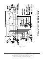
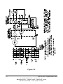
RS-422 and RS-485 Application Note B&B Electronics Mfg. Co. Inc. P.O. Box 1040 -- Ottawa, IL 61350 PH (815) 433-5100 -- FAX (815) 434-7094 Internet Addresses: B&B Home Page: http://www.bb-elec.com Customer Service: [email protected] Technical Support: [email protected] Copyright B&B Electronics -- Revised October 1997 RS-422/485 Application Note Copyright B&B Electronics -- Revised October 1997 B&B Electronics -- PO Box 1040 -- Ottawa, IL 61350 PH (815) 433-5100 -- FAX (815) 434-7094 Cover Page Table of Contents CHAPTER 1: OVERVIEW ............................................................................... 1 INTRODUCTION ................................................................................................. 1 DATA TRANSMISSION SIGNALS ......................................................................... 1 Unbalanced Line Drivers............................................................................. 1 Balanced Line Drivers ................................................................................. 1 Balanced Line Receivers .............................................................................. 3 EIA STANDARD RS-422 DATA TRANSMISSION................................................. 3 EIA STANDARD RS-485 DATA TRANSMISSION................................................. 6 TRISTATE CONTROL OF AN RS-485 DEVICE USING RTS ................................... 9 SEND DATA CONTROL OF AN RS-485 DEVICE ................................................ 11 CHAPTER 2: SYSTEM CONFIGURATION ............................................... 13 NETWORK TOPOLOGIES .................................................................................. 13 TWO WIRE OR FOUR WIRE SYSTEMS .............................................................. 13 TERMINATION ................................................................................................. 16 BIASING AN RS-485 NETWORK ....................................................................... 17 EXTENDING THE SPECIFICATION...................................................................... 19 CHAPTER 3: SELECTING RS-422 AND RS-485 CABLING .................... 20 NUMBER OF CONDUCTORS.............................................................................. 20 SHIELDING ...................................................................................................... 20 CABLE CHARACTERISTICS............................................................................... 20 CHAPTER 4: TRANSIENT PROTECTION OF RS-422 AND RS-485 SYSTEMS......................................................................................................... 23 WHAT DOES A SURGE LOOK LIKE?................................................................... 23 Surge Specifications................................................................................... 23 Common Mode vs. Differential Mode ........................................................ 25 GROUND ≠ GROUND ....................................................................................... 26 TRANSIENT PROTECTION USING ISOLATION ..................................................... 27 Isolation Theory ......................................................................................... 27 Isolation Devices........................................................................................ 28 TRANSIENT PROTECTION USING SHUNTING ..................................................... 28 Shunting Theory ......................................................................................... 28 Connecting Signal Grounds ....................................................................... 29 Shunting Devices........................................................................................ 29 COMBINING ISOLATION AND SHUNTING .......................................................... 29 SPECIAL CONSIDERATION FOR FAULT CONDITIONS ......................................... 31 CHOOSING THE RIGHT PROTECTION FOR YOUR SYSTEM ................................... 31 RS-422/485 Application Note Table of Contents Copyright B&B Electronics -- Revised October 1997 B&B Electronics -- PO Box 1040 -- Ottawa, IL 61350 PH (815) 433-5100 -- FAX (815) 434-7094 i CHAPTER 5: SOFTWARE ........................................................................... 33 INTRODUCTION ............................................................................................... 33 RS-422 SYSTEMS............................................................................................ 33 RS-485 DRIVER CONTROL .............................................................................. 33 RS-485 RECEIVER CONTROL .......................................................................... 34 MASTER-SLAVE SYSTEMS............................................................................... 34 Four Wire Master-Slave Systems ............................................................... 34 Two Wire Master-Slave Systems ................................................................ 34 MULTI-MASTER RS-485 SYSTEMS ................................................................. 35 SYSTEMS WITH PORT POWERED CONVERTERS ................................................ 35 CHAPTER 6: SELECTING RS-485 DEVICES........................................... 36 CHAPTER 7: SOURCES OF FURTHER INFORMATION...................... 37 APPENDIX A: EIA SPECIFICATION SUMMARY .................................. 38 APPENDIX B: EIA STANDARD RS-423 DATA TRANSMISSION......... 40 ii Table of Contents RS-422/485 Application Note Copyright B&B Electronics -- Revised October 1997 B&B Electronics -- PO Box 1040 -- Ottawa, IL 61350 PH (815) 433-5100 -- FAX (815) 434-7094 Chapter 1: Overview Introduction The purpose of this application note is to describe the main elements of an RS-422 and RS-485 system. This application note attempts to cover enough technical details so that the system designer will have considered all the important aspects in his data system design. Since both RS-422 and RS-485 are data transmission systems that use balanced differential signals, it is appropriate to discuss both systems in the same application note. Throughout this application note the generic terms of RS-422 and RS-485 will be used to represent the EIA/TIA-422 and EIA/TIA-485 Standards. Data Transmission Signals Unbalanced Line Drivers Each signal that transmits in an RS-232 unbalanced data transmission system appears on the interface connector as a voltage with reference to a signal ground. For example, the transmitted data (TD) from a DTE device appears on pin 2 with respect to pin 7 (signal ground) on a DB-25 connector. This voltage will be negative if the line is idle and alternate between that negative level and a positive level when data is sent with a magnitude of ±5 to ±15 volts. The RS232 receiver typically operates within the voltage range of +3 to +12 and -3 to -12 volts as shown in Figure 1.1. Balanced Line Drivers In a balanced differential system the voltage produced by the driver appears across a pair of signal lines that transmit only one signal. Figure 1.2 shows a schematic symbol for a balanced line driver and the voltages that exist. A balanced line driver will produce a voltage from 2 to 6 volts across its A and B output terminals and will have a signal ground (C) connection. Although proper connection to the signal ground is important, it isn't used by a balanced line receiver in determining the logic state of the data line. A balanced line driver can also have an input signal called an “Enable” signal. The purpose of this signal is to connect the driver to its output terminals, A and B. If the “Enable” signal is OFF, one can consider the driver as disconnected from the transmission line. An RS-485 driver must have the “Enable” control signal. An RS-422 driver may have this signal, but it is not always required. The disconnected or "disabled" condition of the line driver usually is referred to as the “tristate1” condition of the driver. 1 The term “tristate” comes from the fact that there is a third output state of an RS-485 driver, in addition to the output states of “1” and “0.” RS-422/485 Application Note 1 Copyright B&B Electronics -- Revised October 1997 B&B Electronics -- PO Box 1040 -- Ottawa, IL 61350 PH (815) 433-5100 -- FAX (815) 434-7094 Figure 1.1 Figure 1.2 2 RS-422/485 Application Note Copyright B&B Electronics -- Revised October 1997 B&B Electronics -- PO Box 1040 -- Ottawa, IL 61350 PH (815) 433-5100 -- FAX (815) 434-7094 Balanced Line Receivers A balanced differential line receiver senses the voltage state of the transmission line across two signal input lines, A and B. It will also have a signal ground (C) that is necessary in making the proper interface connection. Figure 1.3 is a schematic symbol for a balanced differential line receiver. Figure 1.3 also shows the voltages that are important to the balanced line receiver. If the differential input voltage Vab is greater than +200 mV the receiver will have a specific logic state on its output terminal. If the input voltage is reversed to less than -200 mV the receiver will create the opposite logic state on its output terminal. The input voltages that a balanced line receiver must sense are shown in Figure 1.3. The 200 mV to 6 V range is required to allow for attenuation on the transmission line. EIA Standard RS-422 Data Transmission The EIA Standard RS-422-A entitled “Electrical Characteristics of Balanced Voltage Digital Interface Circuits” defines the characteristics of RS422 interface circuits. Figure 1.4 is a typical RS-422 four-wire interface. Notice that five conductors are used. Each generator or driver can drive up to ten (10) receivers. The two signaling states of the line are defined as follows: a. When the “A” terminal of the driver is negative with respect to the “B” terminal, the line is in a binary 1 (MARK or OFF) state. b. When the “A” terminal of the driver is positive with respect to the “B” terminal, the line is in a binary 0 (SPACE or ON) state. Figure 1.5 shows the condition of the voltage of the balanced line for an RS-232 to RS-422 converter when the line is in the “idle” condition or OFF state. It also shows the relationship of the “A” and “B” terminals of an RS422 system and the “-“ and “+” terminal markings used on many types of equipment. The “A” terminal is equivalent to the “-“ designation, and the “B” terminal equivalent to the “+” designation. The same relationship shown in Figure 1.5 also applies for RS-485 systems. RS-422 can withstand a common mode voltage (Vcm) of ±7 volts. Common mode voltage is defined as the mean voltage of the A and B terminals with respect to signal ground. RS-422/485 Application Note Copyright B&B Electronics -- Revised October 1997 B&B Electronics -- PO Box 1040 -- Ottawa, IL 61350 PH (815) 433-5100 -- FAX (815) 434-7094 3 Figure 1.3 Figure 1.4 4 RS-422/485 Application Note Copyright B&B Electronics -- Revised October 1997 B&B Electronics -- PO Box 1040 -- Ottawa, IL 61350 PH (815) 433-5100 -- FAX (815) 434-7094 Figure 1.5 RS-422/485 Application Note Copyright B&B Electronics -- Revised October 1997 B&B Electronics -- PO Box 1040 -- Ottawa, IL 61350 PH (815) 433-5100 -- FAX (815) 434-7094 5 EIA Standard RS-485 Data Transmission The RS-485 Standard permits a balanced transmission line to be shared in a party line or multidrop mode. As many as 32 driver/receiver pairs can share a multidrop network. Many characteristics of the drivers and receivers are the same as RS-422. The range of the common mode voltage Vcm that the driver and receiver can tolerate is expanded to +12 to -7 volts. Since the driver can be disconnected or tristated from the line, it must withstand this common mode voltage range while in the tristate condition. Some RS-422 drivers, even with tristate capability, will not withstand the full Vcm voltage range of +12 to -7 volts. Figure 1.6 shows a typical two-wire multidrop network. Note that the transmission line is terminated on both ends of the line but not at drop points in the middle of the line. Termination should only be used with high data rates and long wiring runs. A detailed discussion of termination can be found in Chapter 2 of this application note. The signal ground line is also recommended in an RS-485 system to keep the common mode voltage that the receiver must accept within the -7 to +12 volt range. Further discussion of grounding can be found in Chapter 3 of this application note. 6 RS-422/485 Application Note Copyright B&B Electronics -- Revised October 1997 B&B Electronics -- PO Box 1040 -- Ottawa, IL 61350 PH (815) 433-5100 -- FAX (815) 434-7094 Figure 1.6 RS-422/485 Application Note Copyright B&B Electronics -- Revised October 1997 B&B Electronics -- PO Box 1040 -- Ottawa, IL 61350 PH (815) 433-5100 -- FAX (815) 434-7094 7 Figure 1.7 8 RS-422/485 Application Note Copyright B&B Electronics -- Revised October 1997 B&B Electronics -- PO Box 1040 -- Ottawa, IL 61350 PH (815) 433-5100 -- FAX (815) 434-7094 An RS-485 network can also be connected in a four-wire mode as shown in Figure 1.7. Note that four data wires and an additional signal ground wire are used in a “four-wire” connection. In a four-wire network it is necessary that one node be a master node and all others be slaves. The network is connected so that the master node communicates to all slave nodes. All slave nodes communicate only with the master node. This network has some advantages with equipment with mixed protocol communications. Since the slave nodes never listen to another slave response to the master, a slave node cannot reply incorrectly to another slave node. Tristate Control of an RS-485 Device using RTS As discussed previously, an RS-485 system must have a driver that can be disconnected from the transmission line when a particular node is not transmitting. In an RS-232 to RS-485 converter or an RS-485 serial card, this may be implemented using the RTS control signal from an asynchronous serial port to enable the RS-485 driver. The RTS line is connected to the RS-485 driver enable such that setting the RTS line to a high (logic 1) state enables the RS-485 driver. Setting the RTS line low (logic 0) puts the driver into the tristate condition. This in effect disconnects the driver from the bus, allowing other nodes to transmit over the same wire pair. Figure 1.8 shows a timing diagram for a typical RS-232 to RS-485 converter. The waveforms show what happens if the VRTS waveform is narrower than the data VSD. This is not the normal situation, but is shown here to illustrate the loss of a portion of the data waveform. When RTS control is used, it is important to be certain that RTS is set high before data is sent. Also, the RTS line must then be set low after the last data bit is sent. This timing is done by the software used to control the serial port and not by the converter. When an RS-485 network is connected in a two-wire multidrop party line mode, the receiver at each node will be connected to the line (see Figure 1.6). The receiver can often be configured to receive an echo of its own data transmission. This is desirable in some systems, and troublesome in others. Be sure to check the data sheet for your converter to determine how the receiver “enable” function is connected. RS-422/485 Application Note Copyright B&B Electronics -- Revised October 1997 B&B Electronics -- PO Box 1040 -- Ottawa, IL 61350 PH (815) 433-5100 -- FAX (815) 434-7094 9 Figure 1.8 10 RS-422/485 Application Note Copyright B&B Electronics -- Revised October 1997 B&B Electronics -- PO Box 1040 -- Ottawa, IL 61350 PH (815) 433-5100 -- FAX (815) 434-7094 Send Data Control of an RS-485 Device Many of B&B Electronics’ RS-232 to RS-485 converters and RS-485 serial cards include special circuitry, which is triggered from the data signal to enable the RS-485 driver. Figure 1.9 is a timing diagram of the important signals used to control a converter of this type. It is important to note that the transmit data line is “disabled” at a fixed interval after the last bit, typically one character length. If this interval is too short, you can miss parts of each character being sent. If this time is too long, your system may try to turn the data line around from transmit to receive before the node (with the Send Data converter) is ready to receive data. If the latter is the case, you will miss portions (or complete characters) at the beginning of a response. RS-422/485 Application Note Copyright B&B Electronics -- Revised October 1997 B&B Electronics -- PO Box 1040 -- Ottawa, IL 61350 PH (815) 433-5100 -- FAX (815) 434-7094 11 Figure 1.9 12 RS-422/485 Application Note Copyright B&B Electronics -- Revised October 1997 B&B Electronics -- PO Box 1040 -- Ottawa, IL 61350 PH (815) 433-5100 -- FAX (815) 434-7094 Chapter 2: System Configuration Network Topologies Network configuration isn’t defined in the RS-422 or RS-485 specification. In most cases the designer can use a configuration that best fits the physical requirements of the system. Two Wire or Four Wire Systems RS-422 systems require a dedicated pair of wires for each signal, a transmit pair, a receive pair and an additional pair for each handshake/control signal used (if required). The tristate capabilities of RS-485 allow a single pair of wires to share transmit and receive signals for half-duplex communications. This “two wire” configuration (note that an additional ground conductor should be used) reduces cabling cost. RS-485 devices may be internally or externally configured for two wire systems. Internally configured RS-485 devices simply provide A and B connections (sometimes labeled “-“ and “+”). Devices configured for four wire communications bring out A and B connections for both the transmit and the receive pairs. The user can connect the transmit lines to the receive lines to create a two wire configuration. The latter type device provides the system designer with the most configuration flexibility. Note that the signal ground line should also be connected in the system. This connection is necessary to keep the Vcm common mode voltage at the receiver within a safe range. The interface circuit may operate without the signal ground connection, but may sacrifice reliability and noise immunity. Figures 2.1 and 2.2 illustrate connections of two and four wire systems. RS-422/485 Application Note Copyright B&B Electronics -- Revised October 1997 B&B Electronics -- PO Box 1040 -- Ottawa, IL 61350 PH (815) 433-5100 -- FAX (815) 434-7094 13 Figure 2.1 Typical RS-485 Four Wire Multidrop Configuration 14 RS-422/485 Application Note Copyright B&B Electronics -- Revised October 1997 B&B Electronics -- PO Box 1040 -- Ottawa, IL 61350 PH (815) 433-5100 -- FAX (815) 434-7094 Figure 2.2 Typical RS-485 Two Wire Multidrop Network RS-422/485 Application Note Copyright B&B Electronics -- Revised October 1997 B&B Electronics -- PO Box 1040 -- Ottawa, IL 61350 PH (815) 433-5100 -- FAX (815) 434-7094 15 Termination Termination is used to match impedance of a node to the impedance of the transmission line being used. When impedance are mismatched, the transmitted signal is not completely absorbed by the load and a portion is reflected back into the transmission line. If the source, transmission line and load impedance are equal these reflections are eliminated. There are disadvantages of termination as well. Termination increases load on the drivers, increases installation complexity, changes biasing requirements and makes system modification more difficult. The decision whether or not to use termination should be based on the cable length and data rate used by the system. A good rule of thumb is if the propagation delay of the data line is much less than one bit width, termination is not needed. This rule makes the assumption that reflections will damp out in several trips up and down the data line. Since the receiving UART will sample the data in the middle of the bit, it is important that the signal level be solid at that point. For example, in a system with 2000 feet of data line the propagation delay can be calculated by multiplying the cable length by the propagation velocity of the cable. This value, typically 66 to 75% of the speed of light (c), is specified by the cable manufacture. For our example, a round trip covers 4000 feet of cable. Using a propagation velocity of 0.66 × c, one round trip is completed in approximately 6.2 µs. If we assume the reflections will damp out in three “round trips” up and down the cable length, the signal will stabilize 18.6 µs after the leading edge of a bit. At 9600 baud one bit is 104 µs wide. Since the reflections are damped out much before the center of the bit, termination is not required. There are several methods of terminating data lines. The method recommended by B&B is parallel termination. A resistor is added in parallel with the receiver’s “A” and “B” lines in order to match the data line characteristic impedance specified by the cable manufacture (120 Ω is a common value). This value describes the intrinsic impedance of the transmission line and is not a function of the line length. A terminating resistor of less than 90 Ω should not be used. Termination resistors should be placed only at the extreme ends of the data line, and no more than two terminations should be placed in any system that does not use repeaters. This type of termination clearly adds heavy DC loading to a system and may overload port powered RS-232 to RS-485 converters. Another type of termination, AC coupled termination, adds a small capacitor in series with the termination resistor to eliminate the DC loading effect. Although this method eliminates DC loading, capacitor selection is highly dependent on the system properties. System 16 RS-422/485 Application Note Copyright B&B Electronics -- Revised October 1997 B&B Electronics -- PO Box 1040 -- Ottawa, IL 61350 PH (815) 433-5100 -- FAX (815) 434-7094 designers interested in AC termination are encouraged to read National Semiconductors Application Note 9032 for further information. Figure 2.3 illustrates both parallel and AC termination on an RS-485 two-wire node. In four-wire systems, the termination is placed across the receiver of the node. Figure 2.3 Parallel and AC Termination Biasing an RS-485 Network When an RS-485 network is in an idle state, all nodes are in listen (receive) mode. Under this condition there are no active drivers on the network, all drivers are tristated. Without anything driving the network, the state of the line is unknown. If the voltage level at the receiver’s A and B inputs is less than ±200 mV the logic level at the output of the receivers will be the value of the last bit received. In order to maintain the proper idle voltage state, bias resistors must be applied to force the data lines to the idle condition. Bias resistors are nothing more than a pullup resistor on the data B line (typically to 5 volts) and a pulldown (to ground) on the data A line. Figure 2.4 illustrates the placement of bias resistors on a transceiver in a twowire configuration. Note that in an RS-485 four-wire configuration, the bias resistors should be placed on the receiver lines. The value of the bias resistors is dependent on termination and number of nodes in the system. The goal is to generate enough DC bias current in the network to maintain a minimum of 200 mV between the B and A data line. Consider the following two examples of bias resistor calculation. 2 Refer to Chapter 7 for information on National Semiconductors Application Notes. RS-422/485 Application Note 17 Copyright B&B Electronics -- Revised October 1997 B&B Electronics -- PO Box 1040 -- Ottawa, IL 61350 PH (815) 433-5100 -- FAX (815) 434-7094 Bias Resistor Bias Resistor Figure 2.4 Transceiver with Bias Resistors Example 1. 10 node, RS-485 network with two 120 Ω termination resistors Each RS-485 node has a load impedance of 12KΩ. 10 nodes in parallel give a load of 1200 Ω. Additionally, the two 120 Ω termination resistors result in another 60 Ω load, for a total load of 57 Ω. Clearly the termination resistors are responsible for a majority of the loading. In order to maintain at least 200mV between the B and A line, we need a bias current of 3.5 mA to flow through the load. To create this bias from a 5V supply a total series resistance of 1428 Ω or less is required. Subtract the 57 Ω that is already part of the load, and we are left with 1371 Ω. Placing half of this value as a pullup to 5V and half as a pulldown to ground gives a maximum bias resistor value of 685Ω for each of the two biasing resistors. 18 RS-422/485 Application Note Copyright B&B Electronics -- Revised October 1997 B&B Electronics -- PO Box 1040 -- Ottawa, IL 61350 PH (815) 433-5100 -- FAX (815) 434-7094 Example 2. 32 node, RS-485 network without termination Each RS-485 node has a load impedance of 12KΩ. 32 nodes in parallel gives a total load of 375 Ω. In order to maintain at least 200 mV across 375Ω we need a current of 0.53 mA. To generate this current from a 5V supply requires a total resistance of 9375Ω maximum. Since 375 Ω of this total is in the receiver load, our bias resistors must add to 9KΩ or less. Notice that very little bias current is required in systems without termination. Bias resistors can be placed anywhere in the network or can be split among multiple nodes. The parallel combination of all bias resistors in a system must be equal to or less than the calculated biasing requirements. B&B Electronics uses 4.7KΩ bias resistors in all RS-485 products. This value is adequate for most systems without termination. The system designer should always calculate the biasing requirements of the network. Symptoms of under biasing range from decreased noise immunity to complete data failure. Over biasing has less effect on a system, the primary result is increased load on the drivers. Systems using port powered RS-232 to RS-485 converters can be sensitive to over biasing. Extending the Specification Some systems require longer distances or higher numbers of nodes than supported by RS-422 or RS-485. Repeaters are commonly used to overcome these barriers. An RS-485 repeater such as B&B Electronics’ 485OP can be placed in a system to divide the load into multiple segments. Each “refreshed” signal is capable of driving another 4000 feet of cable and an additional 31 RS485 loads. Another method of increasing the number of RS-485 nodes is to use low load type RS-485 receivers. These receivers use a higher input impedance to reduce the load on the RS-485 drivers to increase the total number of nodes. There are currently half and quarter load integrated circuit receivers available, extending the total allowable number of nodes to 64 and 128. RS-422/485 Application Note Copyright B&B Electronics -- Revised October 1997 B&B Electronics -- PO Box 1040 -- Ottawa, IL 61350 PH (815) 433-5100 -- FAX (815) 434-7094 19 Chapter 3: Selecting RS-422 and RS-485 Cabling Cable selection for RS-422 and RS-485 systems is often neglected. Attention to a few details in the selection process can prevent the costly prospect of re-pulling thousands of feet of cable. Number of Conductors The signal ground conductor is often overlooked when ordering cable. An extra twisted pair must be specified to have enough conductors to run a signal ground. A two wire system then requires two twisted pair, and a four wire system requires three twisted pair. Shielding It is often hard to quantify if shielded cable is required in an application or not. Since the added cost of shielded cable is usually minimal it is worth installing the first time. Cable Characteristics When choosing a transmission line for RS-422 or RS-485, it is necessary to examine the required distance of the cable and the data rate of the system. The Appendix to EIA RS-422-A Standard presents an empirical curve that relates Cable Length to Data Rate for 24 AWG twisted-pair telephone cable that has a shunt capacitance of 16 pF/ft. and is terminated in 100 ohms (see Figure 3.1). This curve is based on signal quality requirements of: a). Signal rise and fall time equal to, or less than, one-half unit interval at the applicable modulation rate. b). The maximum voltage loss between driver and load of 6 dB. 20 RS-422/485 Application Note Copyright B&B Electronics -- Revised October 1997 B&B Electronics -- PO Box 1040 -- Ottawa, IL 61350 PH (815) 433-5100 -- FAX (815) 434-7094 Figure 3.1 Losses in a transmission line are a combination of AC losses (skin effect), DC conductor loss, leakage, and AC losses in the dielectric. In high quality cable, the conductor losses and the dielectric losses are on the same order of magnitude. Figure 3.2 is included in this application note to point out the significant difference in performance of different cables. This chart shows Attenuation versus Frequency for three different Belden cables. Note that the polyethylene cables offer much lower attenuation than PVC cables. RS-422/485 Application Note Copyright B&B Electronics -- Revised October 1997 B&B Electronics -- PO Box 1040 -- Ottawa, IL 61350 PH (815) 433-5100 -- FAX (815) 434-7094 21 Figure 3.2 Another approach to choosing transmission line is the “E-GRADE Program,” which has been established by Anixter Bros. Inc. Anixter is a worldwide distributor of wiring system products. Under this program, Anixter divides data interface cables into four categories as follows: E-GRADE 1 E-GRADE 2 E-GRADE 3 E-GRADE 4 LIMITED DISTANCE STANDARD DISTANCE EXTENDED DISTANCE MAXIMUM DISTANCE Simple charts are used to help the user select the proper cable without any technical understanding of the cable parameters. This program divides the usage categories into EIA-232-D, EIA-422-A, and EIA-423-A. When using this literature, use the EIA-422-A charts for choosing RS-485 cable. 22 RS-422/485 Application Note Copyright B&B Electronics -- Revised October 1997 B&B Electronics -- PO Box 1040 -- Ottawa, IL 61350 PH (815) 433-5100 -- FAX (815) 434-7094 Chapter 4: Transient Protection of RS-422 and RS-485 Systems The first step towards protecting an RS-422 or RS-485 system from transients is understanding the nature of the energy we are guarding against. Transient energy may come from several sources, most typically environmental conditions or induced by switching heavy inductive loads. What does a surge look like? Surge Specifications While transients may not always conform to industry specifications, both the Institute of Electrical and Electronics Engineers (IEEE) and the International Electrotechnical Commission (IEC) have developed transient models for use in evaluating electrical and electronic equipment for immunity to surges. These models can offer some insight into the types of energy that must be controlled to prevent system damage. Both IEC 1000-4-5: 1995 “Surge Immunity Test” and IEEE C62.41-1991 “IEEE Recommended Practice on Surge Voltages in Low-Voltage AC Power Circuits” define a “1.2/50µs - 8/20µs combination wave” surge which has a 1.2 µs voltage rise time with a 50 µs decay across an open circuit. The specified current waveform has an 8 µs rise time with a 20 µs decay into a short circuit. Open circuit voltages levels from 1 to 6 kV are commonly used in both the positive and negative polarities, although under some circumstances voltages as high as 20 kV may be applied. Figures 4.1 and 4.2 illustrate the combination wave characteristics. In addition, IEEE C62.41 also specifies a 100 kHz “ring wave” test. The ring wave has a 0.5 µs rise time and a decaying oscillation at 100 kHz with source impedance of 12Ω as shown in Figure 4.3. Typical amplitudes for the 100 kHz ring wave also range from 1 – 6 kV. RS-422/485 Application Note Copyright B&B Electronics -- Revised October 1997 B&B Electronics -- PO Box 1040 -- Ottawa, IL 61350 PH (815) 433-5100 -- FAX (815) 434-7094 23 1.2/50 uSecond Voltage Wave 1 0.9 0.8 0.7 V(t) / Vp 0.6 0.5 0.4 0.3 0.2 0.1 0 0 20 40 60 80 100 Time, us Figure 4.1 Combination Wave Voltage Waveform 8/20 uSecond Current Wave 1 0.8 V(t)/Vp 0.6 0.4 0.2 0 0 10 20 30 40 50 Time, us Figure 4.2 Combination Wave Current Waveform 24 RS-422/485 Application Note Copyright B&B Electronics -- Revised October 1997 B&B Electronics -- PO Box 1040 -- Ottawa, IL 61350 PH (815) 433-5100 -- FAX (815) 434-7094 100kHz Ring Wave 1 0.8 0.6 V(t)/Vp 0.4 0.2 0 -0.2 -0.4 -0.6 -0.8 0 5 10 15 Time, us 20 25 30 Figure 4.3 100 kHz Ring Wave Common Mode vs. Differential Mode Identifying the type of surges that may threaten a system is an important part of selecting the appropriate levels and methods of transient protection. Since each of the conductors in a data cable travels through the same physical space, it is reasonable to expect transients caused by environmental or current switching to be “common mode” that is, present on all data and ground conductors within the data cable. In some installations, there may be another source of unwanted energy to consider. If there are high voltage cables running anywhere near the data cables, the potential for a fault condition exists as a result of insulation failures or inadvertent contact by an installer. This type of surge could contact any number of conductors in the data cable, presenting a “differential” surge to the data equipment. Although the voltages and currents associated with this type surge are much lower than the types of surges modeled by ANSI or IEC, they have a particularly destructive quality of their own. Instead of dissipating within several milliseconds, they can exist in a steady state condition on the data network. RS-422/485 Application Note Copyright B&B Electronics -- Revised October 1997 B&B Electronics -- PO Box 1040 -- Ottawa, IL 61350 PH (815) 433-5100 -- FAX (815) 434-7094 25 Ground Differences Realizing that transient energy can be high frequency in nature leads to some disturbing observations. At frequencies of this magnitude, it is difficult to make a low impedance electrical connection between two points due to the inductance of the path between them. Whether that path is several feet of cable or thousands of feet of earth between grounding systems, during a transient event there can be hundreds or thousands of volts potential between different “grounds”. We can no longer assume that two points connected by a wire will be at the same voltage potential. To the system designer this means that although RS-422/485 uses 5V differential signaling, a remote node may see the 5V signal superimposed on a transient of hundreds or thousands of volts with respect to that nodes local ground. It is more intuitive to refer to what is commonly called “signal ground” as a “signal reference”. How do we connect system nodes knowing that these large potential differences between grounds may exist? The first step towards successful protection is to assure that each device in the system is referenced to only one ground, eliminating the path through the device for surge currents searching for a return. There are two approaches to creating this idyllic ground state. The first approach is to isolate the data ground from the host device ground, this is typically done with transformers or optical isolators as shown is Figure 4.4. The second approach is to tie each of the grounds on a device together (typically power ground and data ground) with a low impedance connection as shown in Figure 4.5. These two techniques lead us to the two basic methods of transient protection. Device Vcc Isolated Power Port Data Lines Out Optical Isolation Figure 4.4 Isolated RS-485 Device 26 RS-422/485 Application Note Copyright B&B Electronics -- Revised October 1997 B&B Electronics -- PO Box 1040 -- Ottawa, IL 61350 PH (815) 433-5100 -- FAX (815) 434-7094 Vcc Device Port Data Lines Ground line Local Chassis Ground Connection Figure 4.5 RS-485 Device with Signal Ground Connected to Chassis Ground Transient protection using Isolation Isolation Theory The most universal approach to protecting against transients is to galvanically isolate the data port from the host device circuitry. This method separates the signal reference from any fixed ground. Optical isolators, transformers and fiber optics are all methods commonly used in many types of data networks to isolate I/O circuitry from its host device. In RS-422 and RS485 applications, optical isolators are most common. An optical isolator is an integrated circuit that converts the electrical signal to light and back, eliminating electrical continuity. With an isolated port, the entire isolated circuitry floats to the level of the transient without disrupting data communications. As long as the floating level of the circuitry does not exceed the breakdown rating of the isolators (typically 1000 - 2500 volts) the port will not be damaged. This type of protection does not attempt to absorb or shunt excess energy so it is not sensitive to the length of the transient. Even continuous potential differences will not harm isolated devices. It is important to note that isolators work on common mode transients, they cannot protect against large voltage differences between conductors of a data cable such as those caused by short circuits between data and power circuits. RS-422/485 Application Note Copyright B&B Electronics -- Revised October 1997 B&B Electronics -- PO Box 1040 -- Ottawa, IL 61350 PH (815) 433-5100 -- FAX (815) 434-7094 27 Isolation Devices Optical isolation can be implemented in a number of ways. If a conversion from RS-232 to RS-422 or RS-485 is being made, optically isolated converters are available. Optically isolated ISA bus serial cards can replace existing ports in PC systems. For systems with existing RS-422 or RS-485 ports, an optically isolated repeater can be installed. Examples of each of these type devices can be found in the B&B Electronics Data Communications catalog. Transient Protection using Shunting Shunting Theory Creating one common ground at the host device provides a safe place to divert surge energy as well as a voltage reference to attach surge suppression devices to. Shunting harmful currents to ground before they reach the data port is the job of components such as TVS (often referred to by the trade name Tranzorb), MOV or gas discharge tubes. These devices all work by “clamping” at a set voltage, once the clamp voltage has been exceeded, the devices provide a low impedance connection between terminals. Since this type of device diverts a large amount of energy, it cannot tolerate very long duration or continuous transients. Shunting devices are most often installed from each data line to the local earth ground, and should be selected to begin conducting current at a voltage as close as possible above the systems normal communications levels. For RS-422 and RS-485 systems, the voltage rating selected is typically 6 - 8 volts. These devices typically add some capacitive load to the data lines. This should be considered when designing a system and can be compensated for by derating the total line length to compensate for the added load. Several hundred feet is usually an adequate figure. To apply these type products correctly they should be installed as close to the port to be protected as possible, and the user must provide an extremely low impedance connection to the local earth ground of the unit being protected. This ground connection is crucial to proper operation of the shunting device. The ground connection should be made with heavy gauge wire and kept as short as possible. If the cable must be longer than one meter, copper strap or braided cable intended for grounding purposes must be used for the protection device to be effective. In addition to the high frequency nature of transients, there can be an enormous amount of current present. Several thousand amps typically result from applications of the combination wave test in the ANSI and IEC specification. 28 RS-422/485 Application Note Copyright B&B Electronics -- Revised October 1997 B&B Electronics -- PO Box 1040 -- Ottawa, IL 61350 PH (815) 433-5100 -- FAX (815) 434-7094 Connecting Signal Grounds Since a local ground connection is required at each node implementing shunt type protection, the consequences of connecting remote grounds together must be considered. During transient events a high voltage potential may exist between the remote grounds. Only the impedance in the wire connecting the grounds limits the current that results from this voltage potential. The RS-422 and RS-485 specification both recommend using 100 ohm resistors in series with the signal ground path in order to limit ground currents. Figure 4.6 illustrates the ground connection recommended in the specification. Figure 4.6 Signal Ground Connection between two nodes with 100 ohm resistor Shunting Devices There are two types of shunting devices to choose from. The least expensive type is single stage, which usually consists of a single TVS device on each line. Three stage devices are also available. The first stage of a three stage device is a gas discharge tube, which can handle extremely high currents, but has a high threshold voltage and is too slow to protect solid state circuits. The second stage is a small series impedance which limits current and creates a voltage drop between the first and third stage. The final stage is a TVS device which is fast enough to protect solid state devices and brings the clamping voltage down to a safe level for data circuits. Combining Isolation and Shunting Installing a combination of both types of protection can offer the highest reliability in a system. Figures 4.7 and 4.8 illustrate two means of implementing this level of protection. RS-422/485 Application Note Copyright B&B Electronics -- Revised October 1997 B&B Electronics -- PO Box 1040 -- Ottawa, IL 61350 PH (815) 433-5100 -- FAX (815) 434-7094 29 Device Vcc Isolated Power Shunting Device Port Data Lines Out Ground line Earth Ground Figure 4.7 Isolated node with shunt protection to earth ground Device Shunting Device Vcc Isolated Power Port Data Lines Signal Ground Figure 4.8 Isolated port with ungrounded shunt protection The method shown in Figure 4.7 is recommended, in this case isolation protects the circuit from any voltage drops in the earth ground connection. The shunt devices will prevent a surge from exceeding the breakdown voltage of the isolators as well as handling any differential surges on the cable. Figure 4.8 illustrates a method recommended for cases where there is no way to make an earth ground connection. Here, the shunt device’s function is to protect the port from differential surges, a differential surge will be balanced between conductors by the shunting device, converted to common mode. The isolation provides protection from the common mode transient remaining. 30 RS-422/485 Application Note Copyright B&B Electronics -- Revised October 1997 B&B Electronics -- PO Box 1040 -- Ottawa, IL 61350 PH (815) 433-5100 -- FAX (815) 434-7094 Special Consideration for Fault Conditions Data systems that could be exposed to short circuits to power conductors require an extra measure of protection. In these cases its recommended to add a fuse type device in addition to shunting type suppression, as shown in Figure 4.9. When a short circuit occurs, the shunt suppression will begin conducting, but shunting by itself cannot withstand the steady state currents of this type of surge. A small enough fuse value should be chosen so that the fuse will open before the shunt device is damaged. A typical fuse value is 125 mA. Device Vcc Data Lines 125 mA Fuse Signal Ground Earth Ground Figure 4.9 Fused port protection Choosing the right protection for your system While it is hard to predict what type and level of isolation is correct for a system, an educated guess should be made based on the electrical environment, physical conditions and cost of failures in downtime and repair costs. Systems connected between two power sources, such as building to building, office to factory floor, or any system covering long distances should require some level of transient protection. Table 4.1 is a comparison of transient protection techniques. RS-422/485 Application Note Copyright B&B Electronics -- Revised October 1997 B&B Electronics -- PO Box 1040 -- Ottawa, IL 61350 PH (815) 433-5100 -- FAX (815) 434-7094 31 Table 4.1 Comparison of Protection Techniques Optical Isolation Shunting Requires no ground reference Adds no loading to data lines Higher complexity Effective on common mode transients Not dependent on installation quality Requires an external power source Not affected by long term or continuous transients 32 Must have low impedance ground path Presents additional capacitive loading to data lines Lower complexity, uses passive components Effective on both common and differential mode transients Can be improperly installed by user No power required Subject to damage by long duration transients RS-422/485 Application Note Copyright B&B Electronics -- Revised October 1997 B&B Electronics -- PO Box 1040 -- Ottawa, IL 61350 PH (815) 433-5100 -- FAX (815) 434-7094 Chapter 5: Software Introduction RS-422 and RS-485 are hardware specifications. Software protocol is not discussed in either specification. It is up to the system designer to define a protocol suitable for their system. This chapter we will not attempt to define a protocol standard, but will explain some of the issues that should be considered by the system designer, whether writing or purchasing software. RS-422 Systems RS-422 system software differs little from the familiar point-to-point RS232 communication systems. RS-422 is often used to simply extend the distance between nodes over the capabilities of RS-232. RS-422 can also be used as the master node in a four wire master-slave network described later in this chapter. When selecting or writing software for RS-422 systems the designer should be aware of the signals being used by the hardware in the system. Many RS-422 systems do not implement the hardware handshake lines often found in RS-232 systems due to the cost of running additional conductors over long distances. RS-485 Driver Control The principle difference between RS-422 and RS-485 is that the RS-485 driver can be put into a high impedance, tristate mode, which allows other drivers to transmit over the same pair of wires. There are two methods of tristating an RS-485 driver. The first method is to use a control line, often the RTS handshake line, to enable and disable the driver. This requires that the host software raise the RTS line before beginning a transmission to enable the driver, then lower the RTS line after the completion of the transmission. Since only a single RS-485 driver can be enabled on a network at one time it is important that the driver is disabled as quickly as possible after transmission to avoid two drivers trying to control the lines simultaneously, a condition called line contention. Under some operating systems it can be difficult to lower RTS in a timely manner and this method of driver control should be avoided altogether. The second method of RS-485 driver control we refer to as Automatic Send Data Control. This type of control involves special circuitry that senses when data is being transmitted and automatically enables the driver as well as disabling the driver within one character length of the end of transmission. This is the preferred method of driver control since it reduces software overhead and the number of potential pitfalls for the programmer. RS-422/485 Application Note Copyright B&B Electronics -- Revised October 1997 B&B Electronics -- PO Box 1040 -- Ottawa, IL 61350 PH (815) 433-5100 -- FAX (815) 434-7094 33 RS-485 Receiver Control The RS-485 receiver also has an enable signal. Since RS-485 systems using a two wire configuration connect the driver to receiver in a loopback fashion, this feature is often used to disable the receiver during transmission to prevent the echo of local data. Another approach is to leave the RS-485 receiver enabled and monitor the loopback data for errors which would indicate that line contention has occurred. Although a good loopback signal does not guaranty data integrity it does offer a degree of error detection. Master-Slave Systems A master-slave type system has one node that issues commands to each of the “slave” nodes and processes responses. Slave nodes will not typically transmit data without a request from the master node, and do not communicate with each other. Each slave must have a unique address so that it can be addressed independent of other nodes. These type systems can be configured as two wire or four wire. Four wire systems often use an RS-422 master (the driver is always enabled) and RS-485 slaves to reduce system complexity. Four Wire Master-Slave Systems This configuration reduces software complexity at the host since the driver and receiver are always enabled, at the expense of installing two extra conductors in the system. The Master node simply prefixes commands with the appropriate address of the slave. There are no data echo or turn around delays to consider. Since each of the slave transmitters share the same pair of wires, care must be taken that the master never requests data from multiple nodes simultaneously or data collisions will result. Two Wire Master-Slave Systems Two wire configurations add a small amount of complexity to the system. The RS-485 driver must be tristated when not in use to allow other nodes to use the shared pair of wires. The time delay between the end of a transmission and the tristate condition becomes a very important parameter in this type system. If a slave attempts to reply before the master has tristated the line, a collision will occur and data will be lost. The system designer must know the response time or turn around delay of each of the slave nodes and assure that the master will tristate its driver within that amount of time. B&B Electronics’ Automatic Send Data control circuits tristate the driver within one character length of the end of a transmission. 34 RS-422/485 Application Note Copyright B&B Electronics -- Revised October 1997 B&B Electronics -- PO Box 1040 -- Ottawa, IL 61350 PH (815) 433-5100 -- FAX (815) 434-7094 Multi-Master RS-485 Systems Each node in a multi-master type RS-485 system can initiate its own transmission creating the potential for data collisions. This type system requires the designer to implement a more sophisticated method of error detection, including methods such as line contention detection, acknowledgement of transmissions and a system for resending corrupted data. Systems with Port Powered Converters RS-232 to RS-422 or RS-485 converters that derive their power from the RS-232 port are becoming more common in data systems. A good programming practice is to set unused handshake outputs to a high voltage state in systems using any type of RS-232 to RS-422 or RS-485 converter. This will assure the best possible operating conditions for all converters used. RS-422/485 Application Note Copyright B&B Electronics -- Revised October 1997 B&B Electronics -- PO Box 1040 -- Ottawa, IL 61350 PH (815) 433-5100 -- FAX (815) 434-7094 35 Chapter 6: Selecting RS-485 Devices When purchasing devices for an RS-485 system many pitfalls can be avoided by determining the device’s communications characteristics before the system design is complete. Knowing what questions to ask up front can save a lot of troubleshooting in the field. The following device characteristics are all things that should be answered in the system design stage. 1. 2. 3. 4. 5. 6. 7. 8. Is the device configured for two wire or four wire systems? Is a signal ground connection available? Is the device isolated? Does it contain surge suppression? What value bias resistors (if any) are used in the device? Are they accessible for modification? Is the device terminated? Is it accessible for modification? What is the device’s response time (turn around delay)? What is the programmable address range of the device? What baud rate, or range of baud rates, is supported? If possible it is often useful to have a schematic of the serial port of each device in a system. The schematic can provide additional information that may be useful in troubleshooting or repairing any problems in the data system. 36 RS-422/485 Application Note Copyright B&B Electronics -- Revised October 1997 B&B Electronics -- PO Box 1040 -- Ottawa, IL 61350 PH (815) 433-5100 -- FAX (815) 434-7094 Chapter 7: Sources of Further Information EIA Standards and Publications can be purchased from: GLOBAL ENGINEERING DOCUMENTS 7730 Carondelet Avenue -- Clayton, MO 63105 Phone: (800) 854-7179 -- FAX: (314) 726-6418 GLOBAL ENGINEERING DOCUMENTS 15 Inverness Way East -- Englewood, CO 80112 Phone: (800) 854-7179 -- FAX: (303) 397-2740 Global Engineering Documents web site can be found at http://global.ihs.com. Related data interface standards are: a) EIA-232-E Interface between data terminal equipment and date circuitterminating equipment employing serial binary data interchange (ANSI/IEA-232-D) b) EIA-422-A Electrical characteristics of balanced voltage digital interface circuits c) EIA-423-A Electrical characteristics of unbalanced voltage digital interface circuits d) EIA-485 Standard for electrical characteristics of generators and receivers for use in balanced digital multipoint systems e) EIA-449 General purpose 37-position and 9-position interface for data terminal equipment and data circuit-terminating equipment. f) EIA-530 High speed 25-position interface for data terminal equipment and data circuit-terminating equipment g) EIA/TIA-562 Electrical characteristics for an unbalanced digital interface Manufacturers of integrated circuit data transceivers often offer practical application information for RS-422 and RS-485 systems. National Semiconductor’s Interface Data Book includes a number of excellent applications notes. These notes are also available online at http://www.national.com/. A search engine is provided to search the text of the available application notes. Entering “422” or “485” as search criteria to get a current list of related application notes. RS-422/485 Application Note Copyright B&B Electronics -- Revised October 1997 B&B Electronics -- PO Box 1040 -- Ottawa, IL 61350 PH (815) 433-5100 -- FAX (815) 434-7094 37 Appendix A: EIA Specification Summary EIA RS-422 Specification Summary Parameter Driver Output Voltage Open Circuit Driver Output Voltage Loaded Driver Output Resistance Driver Output Short-Circuit Current Driver Output Rise Time Driver Common Mode Voltage Receiver Sensitivity Receiver Common-Mode Voltage Range Receiver Input Resistance Differential Receiver Voltage Conditions RT = 100 Ω Min Max 10 -10 Units V V V V Ω mA 2 -2 A to B Per output to common RT = 100 Ω 100 ±150 10 RT = 100 Ω % of Bit Width V ±3 Vcm ≤ ±7 -7 ±200 +7 mV V ±10 ±12 Ω V V 4000 Operational: Withstand: EIA RS-485 Specification Summary Parameter Driver Output Voltage Open Circuit Driver Output Voltage Loaded Driver Output ShortCircuit Current Driver Output Rise Time Driver Common Mode Voltage Receiver Sensitivity Receiver Common-Mode Voltage Range Receiver Input Resistance 38 Conditions RLOAD = 54Ω Per output to +12V or –7V RLOAD = 54Ω CLOAD = 50 pF RLOAD = 54Ω Min 1.5 -1.5 1.5 -1.5 Max 6 -6 5 -5 ±250 Units V V V V mA 30 % of Bit Width -1 3 V -7 ±200 +12 -7 ≤ Vcm ≤ +12 mV V Ω 12K RS-422/485 Application Note Copyright B&B Electronics -- Revised October 1997 B&B Electronics -- PO Box 1040 -- Ottawa, IL 61350 PH (815) 433-5100 -- FAX (815) 434-7094 EIA RS-232 Specification Summary Parameter Driver Output Voltage Open Circuit Driver Output Voltage Loaded Conditions 3 KΩ ≤ RL ≤ 7 KΩ -2V ≤ Vo ≤ 2V Driver Output Resistance, Power Off Driver Output Short-Circuit Current Driver Output Slew Rate Maximum Load Capacitance Receiver Input Resistance Receiver Input Threshold Output = Mark Output = Space 3V ≤ VIN ≤ 25V Min Max 25 5 3000 15 Units V 300 V V Ω 500 mA 30 2500 7000 V/µs pF Ω -3 3 V V EIA RS-423 Specification Summary Parameter Driver Output Voltage Open Circuit Driver Output Voltage Loaded Driver Output Resistance Driver Output ShortCircuit Current Driver Output Rise and Fall Time Receiver Sensitivity Receiver Input Resistance Conditions RL = 450 Ω Min 4 -4 3.6 -2V ≤ Vo ≤ 2V Baud Rate ≤ 1K Baud Baud Rate ≥ 1K Baud Vcm ≤ ±7V Max 6 -6 6 Units V V V 50 ±150 Ω mA 300 30 µs % Unit Interval mV Ω ±200 4000 RS-422/485 Application Note Copyright B&B Electronics -- Revised October 1997 B&B Electronics -- PO Box 1040 -- Ottawa, IL 61350 PH (815) 433-5100 -- FAX (815) 434-7094 39 Appendix B: EIA Standard RS-423 Data Transmission RS-423 (EIA-423) is another standard used in point to point communications. RS-423 data transmission uses an unbalanced line driver that connects to an RS-422 type balanced line receiver as shown in Figure B.1. The RS-423 line driver is unique to this system. It produces voltage similar to RS-232 but has a slew rate control input that is used to limit rise times and cross talk on the data lines. Typical adjustment on the slew rate control is from 1 to 100 µs. This is done by the proper selection of one resistor on the wave shape control input. Figure B.1 40 RS-422/485 Application Note Copyright B&B Electronics -- Revised October 1997 B&B Electronics -- PO Box 1040 -- Ottawa, IL 61350 PH (815) 433-5100 -- FAX (815) 434-7094