1
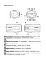
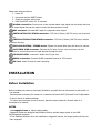
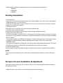
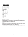
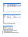
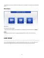
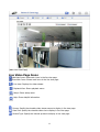
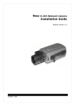
QUICK INSTALLATION GUIDE
HDB-M120
Full HD NETWORK CAMERA
1
DESCRIPTION
------------------------------------------------------------------------------------------------------------------------------------The HDB-M120 Series camera is an internet protocol based megapixel network camera with a builtin web based viewer on Internet Explorer®. The camera has a connection feature for third-party
applications and compatible with supplied Utility software for easy installation and Client software to
search, configure, manage, live view, record and playback.
The camera supports dual compression formats and multiple streaming simultaneously. The two
standard compression formats include H.264 and MJPEG. The multiple streams can be configured to
a variety of resolutions, bit rates and frame rates.
The camera uses 1/2.8 inch CMOS sensor and complies with CS mount lens and also supports PoE
(Power over Ethernet), DC12V, and AC24V.
Model
HDB-M120
Full HD, Day and Night, WDR
Components
Quantity
1
1
1
1
Description
Camera
Installation CD
C- Mount Ring
Auto DC-Iris Connector
NOTE
Lens, installation hardware and Adapter for DC12V / AC24V are not supplied.
2
Camera Layout
RJ-45 connector: Supplies power to the camera through the network using PoE. If PoE is
not available, supplies DC12V or AC24V power source to the POWER connector.
ETHERNET link indication LED: Flashes green to indicate that data is being TX/RX by the
camera.
ETHERNET activity indication LED: Glows solid amber to indicate that a live connection is
established.
STATUS indication LED: Flashes amber about one time per second to indicate normally
working and flashes green about 2~3 time per second while upgrade.
POWER indication LED: Glows solid red if power is supplied properly.
SPEAKER connector: Connect external speaker for audio output.
MIC connector: Supplies external microphone as an audio input source.
POWER connection: Supplies DC12V or AC24V as the power source comply with Class2.
RESET button: Restores the camera’s factory default settings. This button is recessed. Use a
small tool, such as a paper clip, to press the reset button.
3
Please
1.
2.
3.
4.
take steps as follows:
Power off
Press and hold the RESET button
Supply the camera with power
Hold the RESET button for 15 seconds
ALARM connection: Connect one or two physical alarm input signal into the device and one
alarm output signal that can be used to control an external alarm circuit.
BNC connector: Connect BNC cable for composite video output.
INSTALLATION TOP STAND connector: 0.25 Inch (0.64cm) UNC-20 screw, top of camera
housing.
INSTALLATION BOTTOM STAND connector: 0.25 Inch (0.64cm) UNC-20 screw, bottom
of camera housing.
FOCUS ADJUSTING / FIXING screw: Tighten this screw after focus the lens of a camera.
AUTO IRIS LENS connector: Connect the DC auto iris lens 4-pin connector into this
connector to control the amount of light allowed through the lens.
CS MOUNT LENS: connection: Attach the CS type lens.
RS485 connection: Connect RS485 compatible device for PTZ control.
SD Card: Insert SD card for local recording.
INSTALLATION
-------------------------------------------------------------------------------------------------------------------------------------
Before Installation
Before installing the camera, thoroughly familiarize yourself with the information in this section of
the manual.
- Recommends connecting the camera to a network that use a DHCP (Dynamic Host Configuration
Protocol) server to address devices.
- To ensure secure access to the IP camera, place the camera behind a firewall when it is
connected to a network.
NOTES
- Use megapixel lens for higher image quality.
- Megapixel lenses are designed and tested to deliver optimal image quality to the HDBM120megapixel cameras.
- If the standard definition lens was installed on megapixel camera, the image quality will be poor
than expected.
4
- Recommend to install the megapixel lens from the following lens manufactures.
-- TAMRON
-- COMPUTAR
-- FUJINON
Starting Installation
1. Install the Lens
- Be careful the lens does not touch camera sensor when installer try to enter the lens into camera.
- Install manual lens or DC auto iris lens.
- If DC auto iris lens needs to install, connect DC auto iris 4-pin connector into iris drive connector
located on the side of the camera.
2. Mount the camera
The camera can be mounted from both top side and bottom side.
3. Connect other peripheral devices
Connect the other peripheral devices such as Alarm, Audio and BNC connector.
4. Supply the camera with power.
- If PoE is not available, connect DC12V or AC24V wires to the camera power connector. Be careful
when DC12V wiring especially the direction of positive and negative. Use power supply compatible
with FCC Class2.
- This camera complies with IEEE802.3af standard. It means that the power for this camera can be
supplied from Ethernet cabling without additional power supply. This can be reducing the
installation efforts.
- The camera will complete a configuration processing within approximately 40 seconds. The amber
LED flashes one time per second after the configuration processing are complete.
5. View the camera image
View the camera image using BNC connector or built-in web browser or supplied Client software.
NOTE
This camera will autosense and work with either a straight Ethernet cable or crossover Ethernet
cable.
DC Auto Iris Lens Installation & Adjustment
The camera supports DC-type auto iris lenses. Perform the following steps to install and adjust a
DC-type auto iris lens.
- Solder the lens control wires to the connector supplied with the camera.
5
[4-Pin iris driver connector]
- Attach the DC-type auto iris lens to the lens mount on the front of the camera.
- Plug the connector into the auto iris jack on the side of the camera. The connector is polarized
and can be inserting into the iris jack one way.
[DC auto iris Lens connection]
Audio Connection
This camera supports bidirectional audio. Install the microphone and speaker which has an amplifier
capability.
[Audio connection]
External Speaker
External Microphone
Alarm Connection
The camera provides two alarm input for external signaling devices and one alarm output for
activating external device. Both Normally Open and Normally Closed devices are supported. Be
consult before alarm device installation how to wire between the camera and alarm devices.
6
[Alarm connector]
Alarm Input 1
Alarm Ground
Alarm Input 2
Alarm Output
Alarm Ground
RS485 RS485 +
Network Connection
The Network Camera supports the operation through the network. Therefore, it is necessary to
connect a standard RJ-45 cable to it. Generally a cross-over cable is used for directly connection to
PC, while a direct cable is used for connection to a hub.
IP Assignment
When a camera is first connected to the network it has no IP address. So, it is necessary to allocate
an IP address to the device with the “Smart Manager” utility on the CD.
1. Connect the Network Camera / device to the network and power up.
2. Start Smart Manager utility, the main window will be displayed, after a short while any network
devices connected to the network will be displayed in the list.
7
3. Select the camera on the list and click right button of the mouse. You can see the pop-up
menu as below.
4. Select Assign IP. You cam see an Assign IP window.
Enter the required IP address.
The description of each field for the connection status follows.
: Available for connection to the camera
: Loading settings information of video after connecting the camera.
: Connectable to the camera but fixed security settings (password)
8
: Unavailable for connection to the camera (PC can not access relevant IP Address)
Note: For more information, refer to the Smart Manger User’s Manual.
OPERATION
------------------------------------------------------------------------------------------------------------------------------------Before starting the camera, installation must be complete. The camera completes a configuration
sequence within approximately 40 seconds when power is supplied. The amber LED of this
megapixel camera flash one time per second indicating the configuration sequence is complete.
NOTES
- If the DHCP is enabled but the camera is not connected to a DHCP server, the camera will be set
default IP 192.168.30.220 and try to get IP from DHCP server about every two seconds.
- Network and processor bandwidth limitations might cause the video stream to pause or appear
pixilated when an increased number of Web-interface users connection to the camera. Decrease
the images per second, resolution, compression, or bit rate settings of the Web-interface video
streams to compensate for network or processor limitations.
Minimum conditions for using web browser
The minimum system requirements to use a Web browser with this IP camera are as follows:
- CPU: Pentium® 4 microprocessor, 2.0GHz
- Operational System: Windows XP® or Windows Vista® or Windows7®
- System Memory: RAM 512 Mbyte
- Ethernet: 100 Mbit
- Video Resolution: 1024(Horizontal) x 768(Vertical) pixels or higher
- Internet Explorer® 7 or later
- ActiveX® 1.0.0.13 or later
Accessing the IP camera
1. Open Web browser
- Double click Internet Explorer® icon.
2. Type IP address
- Type the camera’s IP address in the Internet Explorer® address bar.
- The default IP address is 192.168.30.220
NOTES
- If you do not know the camera’s IP address, install the SmartManager® utility software available
on the CD supplied with the product. The utility software will locate the assigned Model name,
Host name, MAC address, IP address, Version and others.
- Refer to the SmartManager® utility software manual for more detail.
3. Log On to the camera
9
- Click the Live View icon for default live image view or the Setup icon to change the configuration
values.
Main Menu
[Main Menu]
The dialog box will be appears.
- Type User ID and Password in the dialog box. The default User ID and Password are admin.
NOTE
For security purposes, be sure to change the password after you log on for the first time.
LIVE VIEW
------------------------------------------------------------------------------------------------------------------------------------The Live View page provides you to select the properties of video source. You can view the live
image from this page and also access the Setup menu and operate the main functions.
10
[ Main Live View Page]
Live Video Page Icons
Hide Main Icons: Hides main icons in the live view page.
Show Main Icons: Shows main icons in the live view page.
Live view: Displays live video stream.
Playback View: Enters playback menu.
Setup: Enters setup menu.
Help: Shows helpful information.
Source: Specify the viewable video stream source to display in live view page.
View Size: Specify the viewable video size to display in live view page.
Stream Type: Specify the internet protocol to display in live view page.
11
ROI View: Specify the specially selected area to transfer using different stream feature in the
primary video image. ROI is an abbreviation for “Region of Interest”.
Preset: Specify the Preset. This icon is inactivated if the PTZ settings are not set.
Pause: Pause the live video stream.
Snapshot: Take a picture of the video image currently on display. Supports the origin image
size view, Print, and Save feature.
Digital Zoom: Supports a digital zoom in live video image.
Full Screen: Expands video image to the entire screen area.
Manual Trigger: Activates the Alarm Out signaling manually.
PTZ: Activates a pop-up window for Pan, Tilt and Zoom control.
Speaker: Adjusts the volume of Speaker and switch the sound on / off.
Microphone: Adjusts the volume of Microphone and switch the sound on / off.
Troubleshooting
------------------------------------------------------------------------------------------------------------------------If you suspect a problem is being caused by incorrect configuration or some other minor problem,
consult the troubleshooting guide below.
Upgrading the Firmware
Firmware is software that determines the functionality of the network camera. One of your first
actions when troubleshooting a problem should be to check the current firmware. The latest version
may contain a correction that fixes your particular problem. The current firmware version in your
camera is displayed on the Basic Configuration or About. For the latest firmware of the camera,
please contact with your product administrator.
Detailed instructions on how to perform the upgrade process are provided with each new release.
See also the Maintenancen/ Upgrade for more information.
General Troubleshooting
The following list covers some of the problems that may be encountered and suggests how to
remedy them:
Symptom → Possible Causes or Corrective Actions
1. The camera cannot be accessed by some clients.
12
→ If using a proxy server, try disabling the proxy setting in your browser. Check all cabling and
connectors.
2. The camera works locally, but not externally.
→ Check if there are firewall settings that need to be adjusted. Check if there are router settings
that need to be configured.
3. Poor or intermittent network connection.
→ If using a network switch, check that the port on that device uses the same setting for the
network connection type (speed/duplex).
4. The camera cannot be accessed via a host name.
→ Check that the host name and DNS server settings are correct.
5. Not possible to log in.
→ When HTTPS is enabled, ensure that the correct protocol (HTTP or HTTPS) is used. When
attempting to log in, you may need to manually type in http or https in the browser's address bar.
6. No image using Refresh and/or slow updating of images.
→ If images are very complex, try limiting the number of clients accessing the camera.
7. Images only shown in black & white.
→ Check the Video & Image setting.
8. Blurred images.
→ Refocus the camera.
9. Poor image quality.
→ Increased lighting can often improve image quality. Check that there is sufficient lighting at the
monitored location. Check all image and lighting settings.
10. Rolling dark bands or flickering in image.
→ Try adjusting the Exposure Control setting under AE and AWB part.
11. H.264 not displayed in the client.
→ Check that the correct network interface is selected in the Video & Image/Stream.
12. Multicast H.264 not displayed in the client.
→ Check with your network administrator that the multicast addresses used by the camera are valid
for your network. Check that the Enable multicast checkbox are enabled in the
System/Network/RTP tab. Checks with your network administrator to see if there is a firewall
preventing viewing.
13. Multicast H.264 only accessible by local clients.
→ Check if your router supports multicasting, or if the router settings between the client and the
server need to be configured. The TTL value may need to be increased.
14. Color saturation is different in H.264 and Motion JPEG.
→ Modify the settings for your graphics adapter. Please see the adapter's documentation for more
information.
15. Poor audio quality.
→ Too many users/clients connected to the camera may affect the sound quality adversely. Try
limiting the number of clients allowed to connect.
16. Distorted audio.
→ Check that the correct Audio Input source is selected. Select Microphone for a connected
external microphone. Select Line for a connected line in source.
13
NOTE
If you cannot find the help you require, please see the User's Manual, or contact with your network
administrator.
14