1
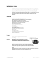
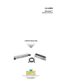
LC-2000
Director™
Lighting Controller
USER MANUAL
CHAUVET, 3000 N 29th Ct, Hollywood, FL 33020 U.S.A
(800) 762-1084 – (954) 929-1115
FAX (954) 929-5560
www.chauvetlighting.com
TABLE OF CONTENT
BEFORE YOU BEGIN....................................................................................................................................................... 3
WHAT IS INCLUDED ................................................................................................................................................................................ 3
UNPACKING INSTRUCTIONS .................................................................................................................................................................... 3
AC POWER........................................................................................................................................................................................... 3
SAFETY INSTRUCTIONS .......................................................................................................................................................................... 3
INTRODUCTION ............................................................................................................................................................... 4
FEATURES ............................................................................................................................................................................................ 4
POWER ................................................................................................................................................................................................ 4
PRODUCT OVERVIEW............................................................................................................................................................................. 5
OPERATING INSTRUCTIONS .......................................................................................................................................... 6
SETUP .................................................................................................................................................................................................. 6
CONTROLLER OVERVIEW ....................................................................................................................................................................... 7
Manual Operations............................................................................................................................................................................................. 7
Running in Chase............................................................................................................................................................................................... 7
Extras.................................................................................................................................................................................................................. 7
APPENDIX ........................................................................................................................................................................ 8
MAINTENANCE ...................................................................................................................................................................................... 8
RETURNS PROCEDURE .......................................................................................................................................................................... 8
CLAIMS ................................................................................................................................................................................................ 8
GENERAL TROUBLESHOOTING ................................................................................................................................................................ 9
TECHNICAL SPECIFICATIONS ................................................................................................................................................................ 10
LC-2000 Users Manual
2
Revision: 2005-01-31/18:26
BEFORE YOU BEGIN
What is included
1 x Director Controller (LC-2000)
1 x Director Relay Pack (LCR-2005)
1 x 9-pin cable (SF-EXCB)
Warranty Card & Manual
Unpacking Instructions
Immediately upon receiving a fixture, carefully unpack the carton, check the contents to ensure that
all parts are present, and have been received in good condition. Notify the shipper immediately and
retain packing material for inspection if any parts appear damaged from shipping or the carton itself
shows signs of mishandling. Save the carton and all packing materials. In the event that a fixture
must be returned to the factory, it is important that the fixture be returned in the original factory box
and packing.
AC Power
To determine the power requirements for a particular fixture, see the label affixed to the back plate of
the fixture or refer to the fixture’s specifications. A fixture’s listed current rating is its average current
draw under normal conditions. All fixtures must be powered directly off a switched circuit and cannot
be run off a rheostat (variable resistor) or dimmer circuit, even if the rheostat or dimmer channel is
used solely for a 0% to 100% switch. Before applying power to a fixture,
Figure 1 - AC Voltage Switch
check that the source voltage matches the fixture’s requirement. Check the
fixture or device carefully to make sure that if a voltage selection switch
exists that it is set to the correct line voltage you will use.
Warning!
Verify that the power select switch on your unit matches the
line voltage applied. All fixtures must be connected to circuits
with a suitable Earth Ground.
Safety Instructions
Please read these instructions carefully, which includes important
information about the installation, usage and maintenance?
•
•
•
•
•
•
•
Please keep this User Guide for future consultation. If you
sell the unit to another user, be sure that they also receive
this instruction booklet.
Always make sure that you are connecting to the proper
voltage and that the line voltage you are connecting to is
not higher than that stated on decal or rear panel of the
fixture.
This product is intended for indoor use only!
To prevent risk of fire or shock, do not expose fixture to
rain or moisture. Make sure there are no flammable
materials close to the unit while operating.
The unit must be installed in a location with adequate
ventilation, at least 50cm from adjacent surfaces. Be sure
that no ventilation slots are blocked.
Always disconnect from power source before servicing or
replacing lamp or fuse and be sure to replace with same
lamp source.
Caution!
•
•
•
•
•
•
Secure fixture to fastening device using a safety chain.
Never carry the fixture solely by its head. Use its carrying
handles.
Maximum ambient temperature is Ta: 40°. Do not operate
fixture at temperatures higher than this.
In the event of serious operating problem, stop using the
unit immediately. Never try to repair the unit by yourself.
Repairs carried out by unskilled people can lead to
damage or malfunction. Please contact the nearest
authorized technical assistance center. Always use the
same type spare parts.
Don’t connect the device to a dimmer pack.
Make sure power cord is never crimped or damaged.
Never disconnect power cord by pulling or tugging on the
cord.
Avoid direct eye exposure to lamp while it is on.
There are no user serviceable parts inside the unit. Do not open the housing or
attempt any repairs yourself. In the unlikely event your unit may require service,
please contact CHAUVET.
LC-2000 Users Manual
3
Revision: 2005-01-31/18:26
INTRODUCTION
The Director™ does the job of two (8-channel) effects lighting controllers in one slim package. This
controller-relay system has two separate (4-channel) chase zones which the user can modify. Each
zone can be switched from audio-activation to any of the two preset timed chases with speed
adjustment rotary knobs. In addition, each 16 individual channel can be overridden and set to
permanently on or always off without affecting the overall chase. You can daisy chain up to 2 runs of
three relay packs and the controller does not require an external power source (see page 6
illustration).
Features
•
•
•
•
•
•
•
•
•
•
•
•
•
•
•
•
•
two (8-channel) effects lighting control panels in one
control of two relay packs at the same time
package includes one relay pack (additional relay packs sold separately)
daisy chain up to 6 relay packs (3 packs per output)
16 independently selectable channels (2 relay packs required)
16 latch buttons with on/off chase override switch
LED indicators for each channel
two user modifiable (4-channel) zones
audio-activation
internal microphone
line level audio input (RCA)
audio sensitivity rotary knob for both zones
timed chase (1sec to 10min) for both zones
blackout button
integrated fog controller
integrated strobe controller with speed knob
19” rack mountable devices
Power
The relay packs are equipped with switch-selectable AC
power setting.
Warning!
Slide switch up or down
depending on your line voltage.
Verify that the power select switch on your unit
matches the line voltage applied. All fixtures must be
connected to circuits with a suitable Earth Ground.
•
•
•
•
•
To determine the power requirements for a particular fixture, see the label
affixed to the back plate of the fixture or refer to the fixture’s specifications chart.
A fixture’s listed current rating is its average current draw under normal conditions.
All fixtures must be powered directly off a switched circuit and cannot be run off a rheostat (variable
resistor) or dimmer circuit, even if the rheostat or dimmer channel is used solely for a 0% to 100%
switch.
Before applying power to a fixture, check that the source voltage matches the fixture’s requirement.
All fixtures must be connected to circuits with a suitable Earth Ground.
LC-2000 Users Manual
4
Revision: 2005-01-31/18:26
Introduction
Product Overview
Power
Audio
Speed
On/Off Switch
Audio sensitivity
knob
(Ch 1~4) & (9~12)
Strobe Speed &
Trigger
Relay A Panel
Latching buttons for
channels 1 ~ 8 on
Relay A output
Blackout
Fogger Control
Speed
Fog trigger and status
indicator
(Ch 5~8) & (13~16)
TM
(2) 4ch Zones
Can be operated
independently
Fogger Remote
Relay Pack
Connections
Relay A and
Relay B
Connect to a CHAUVET
compatible fogger’s
remote output
Relay B Panel
DC Power
Latching buttons for
channels 9 ~ 16 on
Relay B output
Optional power
source (sold
separately)
Audio Line
Input
Strobe
Connector
¼” phone plug for
audio line in
connection
¼” phone plug
connection for strobes
Channel Button & Switches
Each channel provides a “Latch” button for instantly
turning fixtures on and a switch that enables or disables
a channel from running in chase, audio or timer.
Power Input
Controller Input
Switch-selectable
Voltage Settings
Receives signal input
from controller, 9-pin
SF-EXCB
9-pin linking cable
(115V or 230V)
Signal Output
Connect up to two
additional relay packs
using a 9-pin cable
AC 120V~60Hz or
230V~50Hz
Circuit Breaker
Built in 15Amp circuit
breaker
AC Outlets
Duplex
10A max (115V)
5A max (230V)
Power Indicator
LC-2000 Users Manual
5
Revision: 2005-01-31/18:26
OPERATING INSTRUCTIONS
Setup
Action
Notes
1)
Using the 9-pin cable (SF-EXCB) provided,
connect from the Control Output of the
controller to the INPUT on the relay pack.
There are two outputs on the controller, (1~8) is for
Relay A and (9~16) for Relay B.
2)
Plug the relay pack to an AC outlet.
3)
Optional: Continue daisy chain up 3 relay
packs total for each controller 9-pin outputs.
Important! It is recommended that each relay pack
gets powered by independent circuits to avoid
tripping breakers.
4)
Connect desired lighting to the AC outlets
on the relay packs. There are two outlets for
every channel. Both outlets are powered at
the same time.
Do not exceed a maximum load of 15 Amps for 115V
and an individual channel load of 10 Amps.
Two additional relay packs can be daisy chained on
each controller output for a total of 6 relay packs.
RELAY B Panel
RELAY A Panel
Controls channel
outputs (9~16)
Controls channel
outputs (1~8)
LC-2000 Users Manual
6
Revision: 2005-01-31/18:26
Operating Instructions
Controller Overview
M ANU AL O P ER AT IO N S
There are 16 buttons on the Director™. Each button represents an AC duplex outlet on the relay
pack. You can activate an individual channel by pressing the button once. The LED will turn on and
the lighting fixture connected to that output will light. You can turn fixtures on using this method
regardless of whether a chase is currently running. Turning a fixture on using this method will override
the affected channel in the chase.
In addition to the button there is an On/Off Switch. This switch allows you to disable an individual
channel from turning on during the operation of a chase. However, the latch button will still override
and turn on the channel.
The blackout button temporarily disables all outputs on the relay pack causing all lighting fixtures to
turn off. The blackout button can be activated at any time. Blackout button is reset when the power is
turned off.
RU NN ING I N CH AS E
The Director™ is equipped with one standard chase that runs on two (4-channel) zones. Each zone
can be set with three modifiable parameters that affect the running state.
CHASE PARAMETERS
TIMER:
Built in timer can be adjusted from a 10 minutes per step to 1 second per step at max
setting.
CHASE:
A faster timer that can be adjusted from 1 second per step to 1/10th of a second per
step at max. (Recommended for non-inductive loads such as pinspots and
parcans which have no motors internally.)
AUDIO:
When the switch is set to Audio, the sound will trigger the step in the chase.
E XT R AS
The Director™ comes with a simple FOG button and a FOG READY status indicator. Simply connect
from the remote fogger output on the controller into a compatible CHAUVET fogger. The fogger
status indicator will light once the fogger has warmed up and is ready to produce fog.
The STROBE button and STROBE SPEED rotary knob provide control of CHAUVET compatible
mono strobes. Connect a ¼” jack mono cable from the controller to the first strobe and daisy chain
up to 6 strobes. The STROBE SPEED rotary knob affects the speed of the strobe in flashes per
second.
LC-2000 Users Manual
7
Revision: 2005-01-31/18:26
Warranty Information
APPENDIX
Maintenance
To maintain optimum performance and minimize wear fixtures should be cleaned frequently. Usage
and environment are contributing factors in determining frequency. As a general rule, fixtures should
be cleaned at least twice a month. Dust build up reduces light output performance and can cause
overheating. This can lead to reduced lamp life and increased mechanical wear. Be sure to power off
fixture before conducting maintenance.
Unplug fixture from power. Use a vacuum or air compressor and a soft brush to remove dust
collected on external vents and internal components.
Returns Procedure
Returned merchandise must be sent prepaid and in the original packing, call tags will not be issued.
Package must be clearly labeled with a Return Merchandise Authorization Number (RA #). Products
returned without an RA # will be refused. Call CHAUVET and request RA # prior to shipping the
fixture. Be prepared to provide the model number, serial number and a brief description of the cause
for the return. Be sure to properly pack fixture, any shipping damage resulting from inadequate
packaging is the customer’s responsibility. CHAUVET reserves the right to use its own discretion to
repair or replace product(s). As a suggestion, proper UPS packing or double-boxing is always a safe
method to use.
Claims
Damage incurred in shipping is the responsibility of the shipper; therefore the damage must be
reported to the carrier upon receipt of merchandise. It is the customer's responsibility to notify and
submit claims with the shipper in the event that a fixture is damaged due to shipping. Any other claim
for items such as missing component/part, damage not related to shipping, and concealed damage,
must be made within seven (7) days of receiving merchandise.
LC-2000 Users Manual
8
Revision: 2005-01-31/18:26
Operating Instructions
General Troubleshooting
Applies to
Symptom
Solution(s)
Auto shut off
Check fan thermal switch reset
Beam is very dim or not
bright
Clean optical system or replace lamp
Breaker/Fuse keeps
blowing
Check total load placed on device
Chase is too slow
Check users manual for speed adjustment
Device has no power
Lights
Foggers
& Snow
Controllers
Dimmers
& Chaser
Check 220/110v switch for proper setting
Check for power on Mains.
Check device’s fuse. (internal and/or external)
Fixture is not
responding
Check DMX Dip switch settings for correct addressing
Check DMX cables
Check polarity switch settings
Fixture is on but there
is no movement to the
audio
Make sure you have the correct audio mode on the control
switches. If audio provided via ¼” jack, make sure a live
audio signal exists
Adjust sound sensitivity knob
Lamps cuts off
sporadically
Possible bad lamp or fixture is overheating.
Light will not come on
after power failure
Some discharge lamps require a cooling off period before
the electronics in the fixture can kick start it again, wait 5 to
10 minutes before powering up
Loss of signal
Use only DMX cables
Lamp may be at end of its life.
Install terminator
Note: Keep DMX cables separated from power cables or
black lights.
Moves slow
Check 220/110v switch for proper setting
No flash
Re-install bulb, may have shifted in shipping
No laser output
Bounce mirror motor may have shifted during shipping,
readjust
No light output
Check slip ring & brushes for contact
Install bulb
Call service technician
Relay will not work
Check reset switch
Check cable connections
Remote does not work
Make sure connector is firmly connected to device
Stand alone mode
All CHAUVET lighting fixtures featuring stand-alone
functions do not require additional settings, simply power the
fixture and it will automatically enter into this mode
LC-2000 Users Manual
9
Revision: 2005-01-31/18:26
Operating Instructions
Technical Specifications
LC-2000
Length.......................................................................................................................... 101.6 mm (4 in)
Width.......................................................................................................................... 482.6 mm (19 in)
Height ..................................................................................................................... 44.45 mm (1.75 in)
Weight.........................................................................................................................3.81 Kg (8.4 lbs)
Power.............................................................................................. provided by LC-2005 (Relay Pack)
Power (optional) ............................................................................................... DC 9V-12V 200mA min
LC-2005
Length................................................................................................................... 107.95 mm (4.25 in)
Width.......................................................................................................................... 482.6 mm (19 in)
Height ................................................................................................................... 107.95 mm (4.25 in)
Weight.........................................................................................................................2.49 Kg (5.5 lbs)
Switch-selectable power settings.................................................................115V 60 Hz or 230V 50 Hz
European version ............................................................................................................... 240V 50 Hz
AC input ................................................................................. 3-prong IEC 60320 power cord attached
Fuse Protection............................................................................................ Circuit Breaker (15 Amps)
CONTROL
Audio input....................................................................................................................RCA connector
Strobe remote output........................................................ ¼” mono phone plug (TRS) Tip Ring Sleeve
Fogger remote output..................................... CHAUVET compatible using IEC 60320 C-14 connector
ORDERING INFORMATION
Director™................................................................................................................................ LC-2000
Director™ Relay Pack ...........................................................................................................LCR-2005
9-pin cable ............................................................................................................................ SF-EXCB
Fuse 15A ...................................................................................................................... P170FUSE015
LC-2000 Users Manual
10
Revision: 2005-01-31/18:26