1
Page 44
March 7, 2008
TECHNICAL DATA
ESFR PRE-PRIMED SINGLE
INTERLOCK PREACTION
COLD STORAGE SYSTEM
The Viking Corporation, 210 N Industrial Park Road, Hastings MI 49058
Telephone: 269-945-9501 Technical Services 877-384-5464 Fax: 269-945-4495 Email: [email protected]
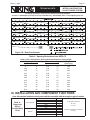
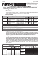
B. Technical Data
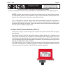
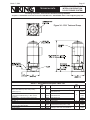
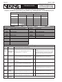
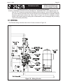
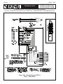
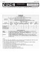
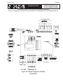
NOTE: The pressure switch (#6) on the CS-1 pump unit is factory set at cut-in pressure
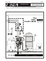
and cut-out pressure. The pressure downstream of the Easy Riser® Check Valve is maintained at 50 PSI Max to 35 PSI Min. (3.4 bar - 2.4 bar) by digital pressure switch (#5).
C. Installation
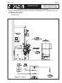
1. Handling
Move the CS-1 on the shipping pallet as close to the final location as possible. Always lift
the unit from underneath. Never lift the unit when it is full of liquid. Personal injury and/or
equipment damage could result.
Ensure that all equipment used to lift the CS-1 is capable of lifting the weight. Nylon straps
and soft rigging devices should be used whenever possible to protect the components and
finish.
If the unit is being transported overhead, be sure that all personnel are alerted and safety
procedures are followed.
2. Location
Install the CS-1 indoors in a clean, dry, non-corrosive environment. This equipment is not to
be installed outdoors exposed to the weather. Position the CS-1 in an upright position on a
solid, level, vibration-free surface capable of supporting the weight of the unit and liquid in
the tank. Bolt the unit to the floor using the bolt holes provided in the frame. Always shim
the unit level before bolting it to the floor. Install the CS-1 in a protected, well-ventilated area
where the ambient temperatures are between 40 °F and 100 °F (4.4 °C to 37.8 °C).
Locate the CS-1 to allow access to supply and discharge connections. Clearance around
the unit should be at least 24” (610 mm) on all sides for maintenance. Some jurisdictions
require specific clearances around equipment. Check with all local Authorities to ensure
compliance with applicable state, local, and national codes.
3. Piping and Connections
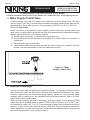
A slight downward slope from the supply container to the CS-1 supply valve connection is
recommended to maintain positive head on the pump inlet.
Always use a backup wrench when making piping connections to avoid damage to the
unit’s piping.
Size piping between the CS-1 and the system 3/4” or greater to minimize pressure
drop. Clean black pipe is acceptable. Too small of a line size restricts pump flow and
causes excessive back pressure, lowering capacity when filling the system. Lower capacity while filling the system requires longer fill times. If the pump stops before obtaining set
system pressure, the CS-1 setting will require being increased. The sprinkler system must
contain air vent/bleed valves at all local high points. These are used to let air out of the
system while filling with antifreeze. Consult the system instructions for specifics.
Individual check valves and isolation valves are required for each system. This allows system maintenance without disturbing other systems the CS-1 is connected to.
Piping and/or hoses from the antifreeze supply containers to the unit should be sloped
downhill slightly to provide positive head on the pump suction connection. These lines
should be as large as possible and as short as possible to provide unrestricted flow to the