1
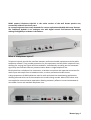
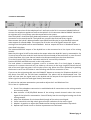
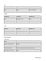
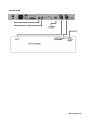
TELEPHONE
HYBRID-2
USER
MANUAL
Version 1.001
Dear Customer,
Thank you for choosing the Telephone Hybrid-2.
This time you are not faced with a huge manual because it is simply not necessary because of
the natural recognition of all functions on the user interface. All functions are self-explanatory
and you will certainly appreciate the ergonomics of this design.
We are confident that you will be using the Telephone Hybrid for many years to come, and
wish you a lot of success with your operation.
With kind regards,
Duco de Rijk
PRESIDENT
D&R ELECTRONICA WEESP B.V.
Rijnkade 15B
1382 GS WEESP-HOLLAND
The Netherlands
Phone: 0294-418 014
Fax: 0294-416 987
Website: http://www.d-r.nl
E-mail: [email protected]
Manual page 2
D&R’s newest Telephone Hybrid-2 is the active version of the well known passive one,
successfully sold over the last 5 years.
Its concept originates from many demands for a more sophisticated hybrid with more features.
The Telephone Hybrid-2 is an analogue unit with digital control and features like ducking
making intelligibility a lot better in broadcast..
What is a telephone hybrid?
Telephone hybrids provide the interface between professional audio equipment and the public
telephone network. They provide protection for your equipment and the public telephone lines,
allowing for varying line signals and line conditions. Automatically canceling out the unwanted
signal they also facilitate two-way communication down a single telephone line.
Each hybrid has a telephone line connection, a handset connection and separate connectors for
audio input and output from a broadcast mixer, or other professional audio source.
A large proportion of D&R hybrids are used in radio and television broadcasting applications
allowing external callers to be connected to the studio mixing console. Most of the other units
are supplied to communication operations allowing extremely effective conversion between 4wire audio circuits and standard telephone lines.
Manual page 3
Front panel lay-out
CONNECT BUTTON:
(RING)
LC:
HC:
Ducking
RECEIVE:
SEND:
Line connect switch to connect and disconnect calls from the
telephone line.
It can be remotely driven by connecting a switch to the GPIO sub D
connector.
Variable Low Cut filter to filter out unwanted low frequency noise.
Variable High Cut filter to filter out unwanted high frequency noise.
Indicates when caller’s signal is reduced.
Level control for incoming signal from caller.
Level control for outgoing signal to caller.
Back panel lay-out
Power
mains power switch.
Power Cord
The unit is powered by a removable IEC type power cord. An internal
switch is provided for 115/230V selection.
LINE:
RJ-12 connector to connect with the public telephone network.
PHONE:
RJ-12 connector to connect with a handset.
C-BALANCE:
8 pole mini-dip switch to select the optimum side tone attenuation.
R-BALANCE
Internal potentiometer to adjust for optimum side tone attenuation.
GPI
Jack connector for remote control. (1:1 for D&R’s Scorpius console)
AUDIO + GPIO
A combination of audio in/outputs and logic for D&R’s Lyra console.
RECEIVE
Male XLR to be connected to input of the mixer.
SEND
Female XLR input to be connected to Mix Minus/Clean feed (N1)output of the mixer.
Manual page 4
SYSTEM DESCRIPTION.
A large ring button enables you to pick up the line from the unit itself or from your mixer when
connected via its GPIO to the telephone Hybrid. When a call comes in it lights up green in the
rhythm of the ring. When the line is picked up by pushing the button it turns into red. When it
starts blinking red the line connection is lost.
Both levels of receive and send can be adjusted to suit your requirements. Incoming signals can
be tailored by the variable high and low cut signal while talking to people calling the station.
A ducking system reduces the incoming signal while talking to people calling the station to
provide for an improved intelligibility.
HIGH LIGHTS.
•
•
•
•
•
•
•
•
Active balanced interfacing.
Variable high and low cut filters.
Industry standard connectors
Superb audio separation.
Externally adjustable R and C balance.
Remotely controllable.
GPIO interfacing with mixing consoles.
Auto Ducking.
Manual page 5
+SETTING UP PROCEDURE
Connect the two wires of the telephone line’s wall unit to the RJ-11 connector labeled LINE and
connect the telephone appliance itself to the Hybrid’s RJ-11 connector labeled PHONE. Note that
to originate calls, a local phone must be connected to the system.
Now the hybrid is interfaced (fully balanced) between your telephone appliance and its
connection to the outside world. The hybrid can now split the send and return signals.
Now connect the hybrid’s balanced audio input (SEND on XLR male) to a (preferable) balanced
mixer output of around +4dBu. This output has to be the mix of all signals except the signal
coming from the hybrid itself to avoid feedback. An Aux. output will do or in broadcast mixers a
clean-feed is the best.
The balanced RECEIVE output of the Hybrid has to be connected to a line input of the mixing
console.
Note that this signal is NOT to be send to the output where the Hybrid’s input is connected to. So
in case of use of an Aux send this local channel Aux send needs to be turned off. In case of use of
a clean-feed buss, this input channel needs to be disconnected from the clean-feed buss.
Turn the LC control fully counter clockwise and the HC control fully clockwise.
Position RECEIVE and SEND controls in their mid position.
If a local phone is connected, originate a call to a remote side. If no local phone is present,
someone at a remote site must call you. When a call comes in the large ring BUTTON on the left
side of the unit lights up green in the rhythm of the ring. When the line is picked up by pushing
the button it turns into red. When it starts blinking red the line connection is lost.
If you are at the originating side pres the CONNECT button to connect the Telephone Hybrid-2 to
the phone line after the call has been established. The phone will be disconnected now. The
caller will now hear the signal send to the Hybrid and the output of the Hybrid will present the
callers signal only with the send signal heavily attenuated.
To achieve the optimum attenuation you need to adjust the C and R balance first.
This is how it is performed:
1. Check if the telephone connection is established and all connections to the mixing console
are correctly wired.
2. Now activate a CUE/PFL/SOLO button of the mixing console channel where the return
signal of the Hybrid is connected to. You will faintly hear the send signal coming out of the
mixing console.
3. Adjust the R-Balance for minimum feed through of the mixers send signal.
4. Listen now which mini-dip switch gives a further reduction of the return signal.
5. Maybe it is good to re-adjust the R-balance after having selected another dip-switch.
6. Repeat steps 3 and 4 until no further improvement are achieved.
Manual page 6
DUCKING
The Hybrid has an automatic gain adjustment of the incoming signal from the caller when the
presenter speaks. This feature both improves the side tone reduction and gives the presenter a
level advantage over the caller when he interrupts the caller. When both parties are speaking the
caller’s signal is reduced then.
INPUTS / OUTPUTS
SEND (to caller)
XLR FEMALE
TYPE
CONNECTION
Pin 1
Screen
Audio ground
Pin 2
Phase
Audio + (input)
Pin 3
Non-phase
Audio – (input)
XLR MALE
TYPE
CONNECTION
Pin 1
Screen
Audio ground
Pin 2
Phase
Audio + (output)
Pin 3
Non-phase
Audio – (output)
GPIO / SEND / RECEIVE
FUNCTION
CONNECTION
Pin 1
Receive (from caller)
Audio + (output)
Pin 6
Receive (from caller)
Audio - (output)
Pin 2
Receive (from caller)
Audio ground
Pin 7
Send (to caller)
Audio + (input)
Pin 3
Send (to caller)
Audio – (input)
Pin 8
Send (to caller)
Audio ground
Pin 4
Logic ground
47 Ohm to ground
Pin 9
GPI
+ 5volt TTL input
Pin 5
GPO
Open collector to ground
RECEIVE (from caller)
SUB D-9 AUDIO + GPIO
Manual page 7
GPI
GPI
FUNCTION
CONNECTION
Tip
Pull down
47 ohm to ground
Ring
Pull up
+5 volt via 10kohm
Sleeve
No
Not connected
PHONE RJ12
FUNCTION
CONNECTION
Pin 1
n.c.
Pin 2
A (telephone line)
In/out
Pin 3
B (telephone line)
In/out
Pin 4
n.c.
PHONE
LINE
LINE RJ12
FUNCTION
CONNECTION
Pin 1
n.c.
Pin 2
A (telephone line)
In/out
Pin 3
B (telephone line)
In/out
Pin 4
n.c.
SPECIFICATIONS
Audio Inputs
SEND
Impedance
10k Ohm, electronically balanced
Common mode rejection
>40dB
Maximum input level
+26dBu
Nominal input level
+4 dBu
Frequency response
20Hz – 15kHz (-3dB variable via HC and LC filters)
Connectors
XLR type 3 pin female
Gain range receive control
40dB
Manual page 8
RECEIVE
Impedance
< 50 Ohm, electronically balanced
Common mode rejection
>40dB
Maximum output level
+26dBu
Nominal output level
+4 dBu
Bandwidth to telephone line
250Hz – 4kHz, -3dB ref 1 kHz
Telephone line impedance
Nominally 600 ohm
Telephone line impedance
range
300 ohm to 1500 ohm
Connectors
XLR type 3 pin male
Gain range send control
+6dB to –20dB
GENERAL
Distortion
Less than 0.1% (0dBu out)
Power supply
115v / 230 v AC / 50/60Hz (factory set, NOT do this yourself)
Power consumption
10VA Maximum
Dimensions
1 HE front panel: 482x44mm
Frame: 430x41x175mm (width x height x depth)
Weight
2.2 kg net excl packing
Manual page 9
INSTALLATION
Manual page 10
DECLARATION OF CONFORMITY
Manufacturers Name:
D&R Electronica Weesp b.v.
Manufacturers Address:
Rijnkade 15
1382 GS Weesp,
The Netherlands
declares that the product
TELEPHONE HYBRID-2
Which refers to this declaration, is in accordance with the following
standards or standardized documents:
EN 50081-1
EN 50082-1
EN 60065
EN 55020
EN 55013 A 12
EN 55022
EN 61000-3-2
EN 61000-3-3
Supplementary Information:
The products herewith complies with the requirements of the EMC Directive 89/336/EWG and
73/23/EWG as amended by the CE Marking Directive 93/68/EEC (1993).
Duco de Rijk
president
August 2003
D&R Electronica Weesp b.v.
Rijnkade 15 B
1382 GS WEESP
The Netherlands
Manual page 11
PRODUCT SAFETY
This product is manufactured with the highest standards and is double checked
in our quality control department for reliability in the "HIGH VOLTAGE" section.
CAUTION
Never remove any panels, or open this equipment. No user serviceable parts
inside.
Equipment power supply must be grounded at all times.
Only use this product as described, in user manual or brochure.
Do not operate this equipment in high humidity or expose it to water or other
liquids.
Check the AC power supply cable to assure secure contact.
Have your equipment checked yearly by a qualified dealer service center.
Hazardous electrical shock can be avoided by carefully following the above
rules.
PLEASE READ THE FOLLOWING INFORMATION
Especially in sound equipment on stage the following information is essential to know.
An electrical shock is caused by voltage and current, actually it is the current that causes the
shock.
In practice the higher the voltage the higher the current will be and the higher the shock.
But there is another thing to consider and it is resistance.
When the resistance in Ohms is high between two poles, the current will be low and vice versa.
All three of these; voltage, current. and resistance are important in determining the effect of an
electrical shock.
However, the severity of a shock primarily determined by the amount of current flowing
through a person.
A person can feel a shock because the muscles in a body respond to electrical current and
because the heart is a muscle it can affect, when the current is high enough.
Current can also be fatal when it causes the chest muscles to contract and stop breathing. At
what potential is current dangerous.
Well the first feeling of current is a tingle at 0.001 Amp of current.
The current between 0.1 Amp and 0.2 Amp is fatal.
Imagine that your home fuses of 20 Amp can handle 200 times more current than is necessary
to kill. How does resistance affect the shock a person feels.
A typical resistance between one hand to the other in "dry" condition could well over
100,000 Ohm.
If you are playing on stage your body is perspiring extensively and your body resistance is
lowered by more than 50%. This is a situation in which current can easily flow.
Current will flow when there is a difference in ground potential between equipment on stage
and in the P.A. system. Please do check if there is any potential between the housing of the
mikes and the guitar synth amps, which will be linked by your body on stage. Imagine, a guitar
in your hand and your lips close to the mike! A ground potential difference of above 10 volts is
not unusual, in improperly wired buildings it can possibly be as high as 240 volts. Although
Manual page 12
removing the ground wire sometimes cures a system hum, it will create a very hazardous
situation for the performing musician.
Always earth all your equipment by the grounding pin in your mains plug.
Hum loops should be only cured by proper wiring and isolation input/output transformers.
Replace fuses always with the same type and rating after the equipment has been turned off
and unplugged.
If the fuse blows again you have an equipment failure, do not use it again and return it to your
dealer for repair.
And last but not least be careful not to touch a person being shocked as you, yourself could
also be shocked.
Once removed from the shock, have someone send for medical help immediately
Always keep the above mentioned information in mind
when using electrically powered equipment.
Manual page 13
Hinweisezum Anschluss
Technische
des Telefonhybrids
RJ11/KeineFunktiondesTelefons:
Anschlussbelegung
funktioniert.
Manchmal
kommtesvor,dasseinTelefonnichtamTelefonhybrid
Diesliegtnichtan
(RJ11)
Anschlussbelegungen
derTelefonleitungen
einemGerdtedefekt,
sondernan unterschiedlichen
flihrenwir dierichtigeBelegung
dereinzelnen
Stecker
auf,damitder
amTelefon.Nachfolgenden
Telefonhybrid
betrieben
werdenkann:
(Wandanschl
TAE-Stecker
uss):
F-Codierung:
Abk.f0r "Fernsprecher-Codierung".
DurchNasenam
vonTelefonen
immernur in F-Buchsen
Steckerpassen
dieStecker
Anschlussdose.
fi
TAEder
t€odorune
rlE.3-f'Srcc*r
F{orhutg
t
[a oder a1
a-Leitungsader
weiB
2 Lb oder bl
b-Leitungsader
braun
?
W
ExternerWecker/Kl
ingel
grtin
4
E
Erdefi.irNebenstelle
gelb
5 b2
6 a2
b-Leitungsader
vom Gerdt
zurlick
a-Leitungsader
vom Gerdt
zurtick
Ftirden BetriebdesTelefons
unddesTelefonhybrids
istdie Belegung
1 und2 erforderlich.
RJI l-Stecker(Western-Stecker):
BelegungTelefonhybrid(PHON
E+ LlNE)
6 Kontakte(davon4 belegt),Westernstecker
6P4C.DiebeideniuBerenKontaktefehlen.
1 = frei
2 -- frei
3 = La oderal a-Leitungsader
4 = Lb oder b1 b-Leitungsader
5 = frei
5 = frei
www.michael-schoebel.de
Seitel von3
L2/2008
Technische
Hinweisezum Anschluss
des Telelonhybrids
RJll-Stecker (Western-Stecker):
BelegungTelefonInternationaleNorm
6 Kontakte(davon4 belegt),Westernstecker
6P4C.DiebeideniuBerenKontaktefehlen.
- KabelamTelefonhybrid
funktionieren
mit jedemStandard
Telefonemit dieserBeschaltung
1 = frei
2 = frei
3 = Laodera1 a-Leitungsader
4 = Lboder b1 b-Leitungsader
5 = frei
6 = frei
BelegungTelefon(2.T.Telekom/ Siemens)
RJll-stecker(Western-Stecker):
5 Kontakte(davon4 belegt),Westernstecker
5P4C.DiebeideniuBerenKontaktefehlen.
F0rden BetriebbestimmterTelefonemussein angepasstes
Kabelvenrendetwerden,sonstist kein
Telefons
m6glich.
Betriebdes
1 = frei
2 = Lboder b1 b-Leitungsader
3 = frei
4 = frei
5 = Laodera1 a-Leitungsader
6 = frei
DerHerstellerhat meistensfolgendesKabelim Lieferumfang:
TAE.F
1
2
RJ11
---> 5 = Laodera1 a-Leitungsader
Laodera1 a-Leitungsader
---> 2 = Lboderb1 b-Leitungsader
Lboderb1 b-Leitungsader
WenndiesesKabelin denHybridgesteckt
wird,ist keineFunktionm6glich,
da dasGerdtauf3 und4
funktioniert
undnichtauf5 und2 !!!
www.michael-schoebel.de
Seite2 von 3
t2l2OO8
TechnischeHinweisezum AnschlussdesTelefonhybrids
Hierder Belerunqsplan
alsGesamttibersicht
1 = a-Leitungsader
2 = b-Leltungsader
3 = frei
4 =trei
5 = frei
6 = frei
-
./e)
ffir' tffir
\--r
,/g)
ffi/
tffir
\_J
1 = frei
2 = lrei
3 = a-Leitungsader
4 = b'Leitungsader
5 = frei
6 = frei
1 = frei
2 = lrei
3 = a-Leitungsader
4 = b-Leitungsader
5 = frei
6 = frei
1 = frei
2 = trei
3 = a-Leitungsader
4 = b-Leitungsader
5 = frei
6 = frei
oder
Bei Nichtfunkion desTelefons,ist die Beleouno
desRl77 - Steckercauf 5 und 2 zu dndern lll
www.michae
l-schoebel.de
Seite3 von 3
1 = frei
2 = b-Leitungsader
3 = frei
4 = trei
5 = a-Leitungsader
6 = frei
t2l2008
TELEPHONE
HYBRID-2
SERVICE
MANUAL
Manual page 14