1
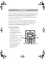
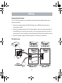
ControlSpace® CC-16 Zone Controller
Safety Instructions
&
Install Guide
Important Safety Instructions
For the intended audience
This guide has been written for professional installers of sound systems.
1. Read these instructions – for all components before using this product.
2. Keep these instructions – for future reference.
3. Heed all warnings – on the product and in the installer’s guide.
4. Follow all instructions.
5. Do not use this apparatus near water or moisture.
6. Clean only with a dry cloth – and as directed by Bose.
7. Do not block any ventilation openings. Install in accordance with the
manufacturer’s instructions.
8. Do not install near any heat sources, such as radiators, heat registers, stoves or
other apparatus (including amplifiers) that produce heat.
9. Refer all servicing to qualified service personnel. Servicing is required when the
apparatus has been damaged in any way such as: power-supply cord or plug is
damaged; liquid has been spilled or objects have fallen into the apparatus; the
apparatus has been exposed to rain or moisture, does not operate normally, or has
been dropped. Do not attempt to service this product yourself. Opening or removing
covers may expose you to dangerous voltages or other hazards. Please call Bose to be
referred to an authorized service center near you.
10. Do not let objects or liquids enter the product – as they may touch dangerous voltage
points or short-out parts that could result in a fire or electric shock.
11. See product enclosure for safety related markings.
12. Only use attachments/accessories specified by the manufacturer.
©2005 Bose Corporation. No part of this work may be reproduced, modified, distributed or otherwise used without prior
written permission.
2
Important Safety Instructions
Information about products that generate electrical noise
This equipment has been tested and found to comply with the limits for a Class B digital device,
pursuant to Part 15 of the FCC rules. These limits are designed to provide reasonable protection against harmful interference in a residential installation. This equipment generates, uses,
and can radiate radio frequency energy and, if not installed and used in accordance with the
instructions, may cause harmful interference to radio communications. However, this is no
guarantee that interference will not occur in a particular installation. If this equipment does
cause harmful interference to radio or television reception, which can be determined by turning
the equipment off and on, you are encouraged to try to correct the interference by one or more
of the following measures:
•
Reorient or relocate the receiving antenna.
•
Increase the separation between the equipment and receiver.
•
Connect the equipment to an outlet on a different circuit than the one to which the
•
Consult the dealer or an experienced radio/TV technician for help.
receiver is connected.
This product complies with the Canadian ICES-003 Class B specifications.
The information furnished in this install guide does not include all of the details of design,
production, or variations of the equipment. Nor does it cover every possible situation which may
arise during installation, operation, or maintenance. If you need assistance beyond the scope of
this user’s guide, please contact our Customer Service department.
3
Important Safety Instructions
Caution
Check local regulations before installing the ControlSpace® CC-16 zone controller. The
building code may require professional installation by a skilled technician or licensed
contractor. Regional electrical codes may require similar qualifications for wiring the system.
This product must be used with a Class 2 power supply.
Please read this install guide
The CC-16 zone controller is engineered to provide customized on-site controls for
ControlSpace sound systems. Please read this guide to help you install and use your
controller correctly.
Regulatory information
An example of this equipment has been tested and found to comply with the following
International Standards for Electromagnetic Compatibility:
Radiated Emissions (EU) EN55103-1
Immunity (EU) EN55103-2
Radiated Emissions (USA): FCC part 15 Class B
This Class B device meets all requirements of the Canadian Interference-Causing
Equipment Regulations.
4
Introduction
The Bose® ControlSpace® CC-16 zone controller is an elegant wall-mounted device designed
to provide end-user control of ControlSpace systems. Custom programming allows the CC-16
to control a variety of the system elements, from switching audio sources to selecting
“scenes” or system configurations. The CC-16 features a bitmap LCD and four buttons for
displaying and controlling the system settings.
The CC-16 connects to the ControlSpace Engineered Sound Processor (ESP-88) at the
RS-485 port. Up to fifteen CC-16 units can be used per each ESP-88 to provide localized
control of the system. The maximum distance from ESP-88 to CC-16 is 2000 feet. As a
networked device, remote reprogramming is possible at any time.
Features and functions
• 122 x 32 pixel backlit blue LCD
• LCD displays volume level and
source/scene/preset setting
• Select up/down buttons for selecting
sources or scenes
• Volume up/down buttons for controlling
one or more gain controls
• IR receiver (for IR remote controls)
• RS-485 network supports up to fifteen
CC-16 units per ESP-88
• DIP-switch for specifying network
address and termination
• Universal mounting bracket
• UL and CE listed
5
Introduction
Quick start
1. Run power and network (2-wire) cables from the ESP-88 to the CC-16 mounting location
and install a mounting box.
2. Set the DIP switches to define the unit address and termination (see silkscreen on back of
CC-16).
3. Connect the power and network wires to the CC-16’s terminal block and insert unit into
the mounting box.
4. At the ESP-88, connect the network wire to the RS-485 port and connect the power
cable to a power source.
5. Run the ControlSpace® Designer software to configure and test. The CC-16 must be
connected to an ESP and configured with the ControlSpace Designer software before it
can be used. Please refer to the Designer User’s Guide for complete details on configuring
and programming the CC-16 in a ControlSpace system.
CAUTION: The building code may require professional installation by a skilled technician or
licensed contractor.
6
Installation
Cabling
The CC-16 zone controller requires power and network cables. In some cases, these can be
supplied over the same multi-conductor cable. When multiple CC-16s are used, run the
network (and optionally the power cable) from the ESP-88 to each zone controller in a daisy
chain. You can also run multiple home runs from the ESP-88 to each CC-16 in a star
configuration.
Note: The ESP-88 does not supply power to the CC-16 zone controller. A separate power
supply (not included) must be provided. Refer to Power Supply on page 12 for more information about the required power supply.
The CC-16 can be wired using commonly available twisted-pair wire such as 24 AWG
unshielded CAT-5. Only one pair of wires is needed for the network connection. For a daisy
chain wired system, the maximum cable length is 2000 feet (610 meters). For a star topology,
the maximum length is 1000 feet (305 meters).
When supplying power over the same cable as the network pair, the limiting factor will be the
resistive loss in the wire. Smaller-gauge wire, will have higher resistance and cause a larger
voltage drop at the CC-16. The CC-16 requires a minimum of 8VDC. 24 AWG wire has
resistance of about 27 ohms per 1000 feet (305 meters), while 18 AWG wire has a resistance
of about 7 ohms per 1000 feet (305 meters).
The maximum distance can be calculated as follows:
d = ((VSUPPLY – 8V)/(Number of CC-16s * 100mA))/RWIRE )* 1000 feet)
For example, if VSUPPLY is 12V, the number of CC-16s = 2 and RWIRE = 27 (24 AWG), then:
d = ((12V – 8V)/(2 * 100mA))/27) * 1000 feet) = (4/.2/27 *1000 feet ) =750 feet (225 meters)
7
Installation
Maximum cable distances
Wire Gauge/
Power Supply Voltage
Number of CC-16s
2
4
1
15
24 AWG 18V
2000 ft (610 m)
1852 ft (564 m)
926 ft (282 m)
247 ft (75 m)
24 AWG 12V
1481 ft (451 m)
741 ft (226 m)
370 ft (113 m)
99 ft (30 m)
24 AWG 9V
370 ft (113 m)
185 ft (56 m)
93 ft (28 m)
25 ft (7 m)
18 AWG 18V
2000 ft (610 m)
2000 ft (610 m)
2000 ft (610 m) 1010 ft (308 m)
18 AWG 12V
2000 ft (610 m)
2000 ft (610 m)
1515 ft (461 m) 404 ft (123 m)
18 AWG 9V
1515 ft (461 m)
758 ft (231 m)
379 ft (115 m)
101 ft (31 m)
Installing the mounting box
Install a dual-gang electrical box for each CC-16. Install the wall box so that it is flush or just
below the surface of the finished wall. The unit is designed to fit in North American, Japanese,
Australian and some European dual-gang electrical boxes. Mount the European and Australian
double-gang boxes horizontally and the North American and Japanese boxes vertically as
shown below.
Select a place that is convenient for the people who
will be controlling the system. We suggest mounting
the unit at eye-level for optimal LCD viewing angle.
CAUTION: Do not install the CC-16 in a box that has AC power (mains).
CAUTION: Do not place the power or network cables in the same conduit with the mains wire,
unless you are sure that special regulatory insulation requirements are met. Consult your local
electrical regulatory agency for further information.
8
DIP Switch Settings
The CC-16 zone controller has an 8-position DIP switch located on the back of the unit. The
DIP switches control addressing and termination settings.
DIP switch addresses
Up to fifteen CC-16s can be connected to an ESP-88 and each must have a unique
address. Use the DIP switches numbered 4, 5, 6 and 7 on the back of the unit to set the
address – 1 through 15. The addresses are in binary format. Refer to the illustration below
to locate binary addresses and the corresponding switch positions.
9
DIP Switch Settings
Termination
The CC-16 zone controller uses a 2-wire RS-485 network to communicate with the ESP-88
sound processor. For optimum performance, the RS-485 network must be “terminated.” The
CC-16 includes built-in termination resistors which make it easy to terminate the network.
Termination is accomplished by setting DIP switches 1 and 2 to the ON position.
• In most cases, only one CC-16 zone controller – the last unit in the daisy chain network
(furthest away from the ESP-88) should have the termination set to ON.
• In a star topology, with the ESP-88 in the middle of two or more long runs, two units (the
two furthest from the ESP-88) should have the termination set to ON.
Note: Switch 3 (2X) should always be in the ON position.
10
Wiring
Connecting the wires
The CC-16 zone controller uses a standard 6-wire Eurostyle terminal block for power and
network connections.
1. Connect the network cable to the RS-485 A/B pins on the ESP-88. Note which wire is
connected to A and B.
2. Connect the network cable to the CC-16 terminal blocks. Ensure the wire connected to “A”
on the ESP-88 is the same one connected to “A” on the controllers and that the “B-wire” is
connected to “B” on the controllers. Connect Shield to the RS-485 cable shield if necessary.
3. Connect the power supply to the Ground and Vin+ terminals on the controllers.
Wiring Example
11
Wiring
Power supply
The CC-16 zone controller requires a minimum of 100mA at 8VDC. For convenience and
consistency, we recommend you place the power supply in an equipment area adjacent to
the network connection.
Power can be supplied over the network cable, from a power supply local to the unit, or from
a remotely-located power supply with a separate cable run. The required cable AWG is
dependent on the length of the run—the longer the run, the higher the voltage drop in the
cable and the lower the required cable AWG.
Use the ControlSpace® accessory power supply or other suitable supply. Individual country
requirements are:
• North America: Power supplies used in North America must be NRTL listed and/or CSA
certified Class 2 supplies, as appropriate. The supply must comply with one of the following
UL standards: UL6500, UL60950, or UL1310.
• Europe: Power supplies used in Europe must be in compliance with EN/IEC 60950 Clause
2.11.
• Japan: Power supplies used in Japan must be in compliance with DENAN Law and be
marked with the PSE diamond.
CAUTION: Never use more than one power supply on the same wire as this could cause
slight differences in voltage that could damage the power supplies and/or the CC-16.
12
Mounting
Mounting the CC-16 zone controller
Warning: The CC-16 must be installed in a National Electric Code (NEC) approved,
enclosed electrical wall box.
After setting the DIP switches and connecting the wires, mount the CC-16 zone controller in the
electrical box. Two sets of screws are provided. Use the screws that are appropriate for your
wall-box – the #6 for North American boxes, and the M4 for Japanese, European and Australian
boxes.
CAUTION: Do not overtighten the screws. Overtightening may cause the frame to break.
Mounting the CC-16 Zone Controller in a North American 2-gang wall box
After screwing the frame into the wall box, remove the protective clear film and snap on the
cover. The cover can be removed later using a small flathead screwdriver in the slots on the
sides.
13
Troubleshooting
No power
• Ensure that the power supply is wired correctly and plugged in
• Try disconnecting other CC-16s if sharing a supply
• Verify that the supply is DC and provides a minimum 100mA at 8V
Screen is blank
• Press a button to see if backlight comes on (the backlight turns off
after a period of inactivity)
No response when
• Check to see if the device is connected to an ESP-88
Volume or Select
• Check the polarity of the wiring to the ESP-88 (A->A, B->B)
up/down buttons
• Check the DIP switch settings (2X should be ON )
are pressed
• If this is the end of a long run, check that the termination DIP
switches are set to ON
• Check that the Select and/or Volume parameters have been programmed using the Designer software. Refer to the ControlSpace®
Designer Software user’s guide for more information
• Check that the controls have been linked (in the Designer software)
to signal processing blocks in the ESP-88
• Ensure that the CC-16 address (set with DIP switches) matches the
address of the device you programmed in Designer
Power on, but no
• Check that the system is not muted
sound
• Check that other components (sources and amps) are not muted
and are wired correctly
Cannot “find” the
• Verify that an ESP-88 has been added to your design
device in Designer
• Verify that the ESP-88 “finds” the CC-16. (Look for the CC-16 in the
Properties window and be sure it corresponds with the address
you set on the CC-16.)
14
Specifications
Input voltage
8 - 18VDC, 100mA
Max network cable length
2000 feet (609m)
Number of CC-16 zone controllers per ESP-88 Sound Processor
15
Dimensions
15
Warranty
Bose® Product Sales Conditions
Limited Warranty Policy and Conditions of Sale
Bose Corporation
The Mountain, Framingham, MA 01701
What is covered:
All parts defective in material and workmanship. This limited warranty for the Bose® ControlSpace® CC-16 Zone Controller
covers the functionality of the system for its normal, intended use as specified in the Owner’s Guide and does not cover a
malfunction that has resulted from improper or unreasonable use or maintenance, accident, excess moisture, improper
packing, lightning, power surges, or unauthorized tampering, alteration or modification while not under the control of Bose.
Bose systems are not designed to be used in every environment, so please review your Owner’s Guide. WHERE
PERMITTED, THE PROVISIONS OF THIS LIMITED WARRANTY ARE IN LIEU OF ANY OTHER WRITTEN WARRANTY,
WHETHER EXPRESS OR IMPLIED, WRITTEN OR ORAL, INCLUDING ANY WARRANTY OF MERCHANTABILITY OR
FITNESS FOR A PARTICULAR PURPOSE.
For how long:
In countries where the duration of the warranty is not determined by statute, the Bose Limited Warranty lasts five years from
the purchase date. For countries where minimum warranty terms are determined by statute, the warranty term is the longer
of the statutory period or the term listed above.
What we will do:
We will repair or replace any defective parts within a reasonable period of time and free of charge.
How you can obtain warranty service:
1. You can ship the system to either a Bose Service Agency or to Bose directly with a proof of purchase from an authorized
dealer.Please:
A. Properly and carefully pack the product for shipping. If you need a carton for shipping, contact Bose for a new
carton.
B. Label and ship the product to the appropriate Bose location.
C. Please contact Bose to get a return reference number. Place this number prominently on the outside of the carton.
2. You can return the system with proof of purchase from an authorized dealer to a Bose Service Agency or directly to
Bose. Proof of purchase is not required where it is excluded by statute.
16
Warranty
Other Rights:
EXCLUSIVE REMEDY:
THIS LIMITED WARRANTY IS FULLY TRANSFERABLE PROVIDED THAT THE CURRENT OWNER FURNISHES THE
ORIGINAL PROOF OF PURCHASE FROM AN AUTHORIZED BOSE DEALER. THE MAXIMUM LIABILITY OF BOSE SHALL
NOT EXCEED THE ACTUAL PURCHASE PRICE PAID BY YOU FOR THE PRODUCT. IN NO EVENT SHALL BOSE BE
LIABLE FOR SPECIAL, INCIDENTAL, CONSEQUENTIAL OR INDIRECT DAMAGES. SOME PLACES DO NOT ALLOW
LIMITATIONS ON THE EXCLUSION OR LIMITATION OF RELIEF, SPECIAL, INCIDENTAL, CONSEQUENTIAL OR INDIRECT
DAMAGES OF THE LIMITATION OF LIABILITY TO SPECIFIED AMOUNTS, SO THE ABOVE LIMITATIONS OR EXCLUSIONS
MAY NOT APPLY TO YOU.
OTHER CONDITIONS:
FOR YOUR BENEFIT, WE RECOMMEND THAT YOU RECORD YOUR SERIAL NUMBER(S), FOUND ON THE PRODUCT(S),
AND OTHER PURCHASE INFORMATION, AND KEEP IT WITH YOUR PERSONAL RECORDS ALONG WITH PROOF OF
PURCHASE. IF NECESSARY, THIS INFORMATION WILL ALLOW US TO BETTER SERVE YOUR NEEDS.
THIS LIMITED WARRANTY GIVES YOU SPECIFIC RIGHTS SUBJECT TO SPECIFIED CONDITIONS. YOU MAY ALSO HAVE
OTHER LEGAL RIGHTS WHICH APPLY TO THE PRODUCT YOU HAVE ACQUIRED. THESE LEGAL RIGHTS VARY FROM
STATE TO STATE OR COUNTRY TO COUNTRY. SOME PLACES DO NOT ALLOW THE EXCLUSION, RESTRICTION OR
MODIFICATION OF CERTAIN IMPLIED RIGHTS OR THEIR EFFECT. IN THOSE SITUATIONS THIS LIMITED WARRANTY
WILL ONLY APPLY TO THE EXTENT THAT THE APPLICABLE LAW ALLOWS. OTHER LAWS PROVIDE YOU WITH A
STATUTORY CLAIM AGAINST THE SELLER.
The laws of your state or country may provide you with legal claims against the seller or manufacturer of this product. The
Limited Warranty does not affect those rights.
Remedies:
The provisions of this limited warranty are in lieu of any other warranties or conditions, except those provided by law. This
Limited Warranty does not affect any legal rights provided to you by law and does not preclude any legal remedy you may
have under the law.
This Limited Warranty is fully transferable provided that the current owner furnishes the original proof of purchase from an
authorized Bose dealer.
This Limited Warranty is void if the label bearing the serial number has been removed or defaced.
17
18
19
©2007 Bose Corporation, The Mountain,
Framingham, MA 01701-9168 USA
285042 AM Rev.01
20