1
MCP1630 Dual Buck
Demo Board User’s Guide
© 2005 Microchip Technology Inc.
DS51531A
Note the following details of the code protection feature on Microchip devices:
•
Microchip products meet the specification contained in their particular Microchip Data Sheet.
•
Microchip believes that its family of products is one of the most secure families of its kind on the market today, when used in the
intended manner and under normal conditions.
•
There are dishonest and possibly illegal methods used to breach the code protection feature. All of these methods, to our
knowledge, require using the Microchip products in a manner outside the operating specifications contained in Microchip’s Data
Sheets. Most likely, the person doing so is engaged in theft of intellectual property.
•
Microchip is willing to work with the customer who is concerned about the integrity of their code.
•
Neither Microchip nor any other semiconductor manufacturer can guarantee the security of their code. Code protection does not
mean that we are guaranteeing the product as “unbreakable.”
Code protection is constantly evolving. We at Microchip are committed to continuously improving the code protection features of our
products. Attempts to break Microchip’s code protection feature may be a violation of the Digital Millennium Copyright Act. If such acts
allow unauthorized access to your software or other copyrighted work, you may have a right to sue for relief under that Act.
Information contained in this publication regarding device
applications and the like is provided only for your convenience
and may be superseded by updates. It is your responsibility to
ensure that your application meets with your specifications.
MICROCHIP MAKES NO REPRESENTATIONS OR WARRANTIES OF ANY KIND WHETHER EXPRESS OR IMPLIED,
WRITTEN OR ORAL, STATUTORY OR OTHERWISE,
RELATED TO THE INFORMATION, INCLUDING BUT NOT
LIMITED TO ITS CONDITION, QUALITY, PERFORMANCE,
MERCHANTABILITY OR FITNESS FOR PURPOSE.
Microchip disclaims all liability arising from this information and
its use. Use of Microchip’s products as critical components in
life support systems is not authorized except with express
written approval by Microchip. No licenses are conveyed,
implicitly or otherwise, under any Microchip intellectual property
rights.
Trademarks
The Microchip name and logo, the Microchip logo, Accuron,
dsPIC, KEELOQ, microID, MPLAB, PIC, PICmicro, PICSTART,
PRO MATE, PowerSmart, rfPIC, and SmartShunt are
registered trademarks of Microchip Technology Incorporated
in the U.S.A. and other countries.
AmpLab, FilterLab, Migratable Memory, MXDEV, MXLAB,
PICMASTER, SEEVAL, SmartSensor and The Embedded
Control Solutions Company are registered trademarks of
Microchip Technology Incorporated in the U.S.A.
Analog-for-the-Digital Age, Application Maestro, dsPICDEM,
dsPICDEM.net, dsPICworks, ECAN, ECONOMONITOR,
FanSense, FlexROM, fuzzyLAB, In-Circuit Serial
Programming, ICSP, ICEPIC, MPASM, MPLIB, MPLINK,
MPSIM, PICkit, PICDEM, PICDEM.net, PICLAB, PICtail,
PowerCal, PowerInfo, PowerMate, PowerTool, rfLAB,
rfPICDEM, Select Mode, Smart Serial, SmartTel, Total
Endurance and WiperLock are trademarks of Microchip
Technology Incorporated in the U.S.A. and other countries.
SQTP is a service mark of Microchip Technology Incorporated
in the U.S.A.
All other trademarks mentioned herein are property of their
respective companies.
© 2005, Microchip Technology Incorporated, Printed in the
U.S.A., All Rights Reserved.
Printed on recycled paper.
Microchip received ISO/TS-16949:2002 quality system certification for
its worldwide headquarters, design and wafer fabrication facilities in
Chandler and Tempe, Arizona and Mountain View, California in
October 2003. The Company’s quality system processes and
procedures are for its PICmicro® 8-bit MCUs, KEELOQ® code hopping
devices, Serial EEPROMs, microperipherals, nonvolatile memory and
analog products. In addition, Microchip’s quality system for the design
and manufacture of development systems is ISO 9001:2000 certified.
DS51531A-page ii
© 2005 Microchip Technology Inc.
MCP1630 DUAL BUCK DEMO
BOARD USER’S GUIDE
Table of Contents
Preface ........................................................................................................................... 1
Chapter 1. Product Overview ........................................................................................ 5
1.1
1.2
1.3
Introduction ............................................................................................... 5
What is the MCP1630 Dual Buck Demo Board? ...................................... 6
What the MCP1630 Dual Buck Demo Board Kit Includes ........................ 6
Chapter 2. Installation and Operation .......................................................................... 7
2.1
2.2
2.3
Introduction ............................................................................................... 7
Features ................................................................................................... 7
Getting Started ......................................................................................... 7
Appendix A. Schematic and Layouts ........................................................................ 11
A.1
A.2
A.3
A.4
A.5
A.6
A.7
A.8
Introduction and Highlights ..................................................................... 11
Board Schematic - Sheet 1 ................................................................... 12
Board Schematic - Sheet 2 ................................................................... 13
Board Outline ........................................................................................ 14
Board Top Layer ................................................................................... 15
Board Mid-Layer 1 ................................................................................ 16
Board Mid-Layer 2 ................................................................................ 17
Board Bottom Layer .............................................................................. 18
Appendix B. Bill-Of-Materials (BOM) ......................................................................... 19
Appendix C. Evaluation Board Firmware .................................................................. 21
C.1
Device Firmware ..................................................................................... 21
Worldwide Sales and Service .................................................................................... 22
© 2005 Microchip Technology Inc.
DS51531A-page iii
MCP1630 Dual Buck Demo Board User’s Guide
NOTES:
DS51531A-page iv
© 2005 Microchip Technology Inc.
MCP1630 DUAL BUCK DEMO
BOARD USER’S GUIDE
Preface
NOTICE TO CUSTOMERS
All documentation becomes dated, and this manual is no exception. Microchip tools
and documentation are constantly evolving to meet customer needs, so some actual
dialogs and/or tool descriptions may differ from those in this document. Please refer
to our web site (www.microchip.com) to obtain the latest documentation available.
Documents are identified with a “DS” number. This number is located on the bottom
of each page, in front of the page number. The numbering convention for the DS
number is “DSXXXXXA”, where “XXXXX” is the document number and “A” is the
revision level of the document.
For the most up-to-date information on development tools, see the MPLAB® IDE
on-line help. Select the Help menu, and then Topics to open a list of available on-line
help files.
INTRODUCTION
This chapter contains general information that will be useful to know before using the
MCP1630 Dual Buck Demo Board. Items discussed in this chapter include:
•
•
•
•
About This Guide
Recommended Reading
The Microchip Web Site
Customer Support
ABOUT THIS GUIDE
Document Layout
This document describes how to use the MCP1630 Dual Buck Demo Board as a development tool to emulate and debug firmware on a target board. The manual layout is as
follows:
• Chapter 1: Overview – Important information about the MCP1630 Dual Buck
Demo Board.
• Chapter 2: MCP1630 Dual Buck Demo Board – Includes instructions on how to
get started with this demo board and a description of the demo board operation.
• Appendix A: Schematic and Layouts – Shows the schematic and layout
diagrams for the MCP1630 Dual Buck Demo Board.
• Appendix B: Bill-of-Materials – Lists the parts used to build the MCP1630 Dual
Buck Demo Board.
• Appendix C: Firmware - Provides information about the application firmware and
where the source code can be found.
© 2005 Microchip Technology Inc.
DS51531A-page 1
MCP1630 Dual Buck Demo Board User’s Guide
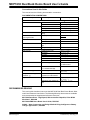
Conventions Used in this Guide
This manual uses the following documentation conventions:
DOCUMENTATION CONVENTIONS
Description
Arial font:
Italic characters
Initial caps
Quotes
Underlined, italic text with
right angle bracket
Bold characters
‘bnnnn
Text in angle brackets < >
Courier font:
Plain Courier
Italic Courier
0xnnnn
Square brackets [ ]
Curly brackets and pipe
character: { | }
Ellipses...
Represents
Examples
Referenced books
Emphasized text
A window
A dialog
A menu selection
A field name in a window or
dialog
A menu path
MPLAB® IDE User’s Guide
...is the only compiler...
the Output window
the Settings dialog
select Enable Programmer
“Save project before build”
A dialog button
A tab
A binary number where n is a
digit
A key on the keyboard
Click OK
Click the Power tab
‘b00100, ‘b10
File>Save
Press <Enter>, <F1>
Sample source code
Filenames
File paths
Keywords
Command-line options
Bit values
A variable argument
#define START
autoexec.bat
c:\mcc18\h
_asm, _endasm, static
-Opa+, -Opa0, 1
file.o, where file can be
any valid filename
A hexadecimal number where 0xFFFF, 0x007A
n is a hexadecimal digit
Optional arguments
mcc18 [options] file
[options]
Choice of mutually exclusive errorlevel {0|1}
arguments; an OR selection
Replaces repeated text
var_name [,
var_name...]
Represents code supplied by void main (void)
user
{ ...
}
RECOMMENDED READING
This user's guide describes how to use the MCP1630 Dual Buck Demo Board. Other
useful documents are listed below. The following Microchip documents are available
and recommended as supplemental reference resources.
MCP1630 Data Sheet, “High-Speed, Microcontroller-Adaptable, Pulse Width
Modulator”, DS21896
MCP1630 NiMH Demo Board User's Guide, DS51505
AN960 - “New Components and Design Methods Bring Intelligence to Battery
Charger Applications”, DS00960
DS51531A-page 2
© 2005 Microchip Technology Inc.
Preface
THE MICROCHIP WEB SITE
Microchip provides online support via our web site at www.microchip.com. This web
site is used as a means to make files and information easily available to customers.
Accessible by using your favorite Internet browser, the web site contains the following
information:
• Product Support – Data sheets and errata, application notes and sample
programs, design resources, user’s guides and hardware support documents,
latest software releases and archived software
• General Technical Support – Frequently Asked Questions (FAQs), technical
support requests, online discussion groups, Microchip consultant program
member listing
• Business of Microchip – Product selector and ordering guides, latest Microchip
press releases, listing of seminars and events, listings of Microchip sales offices,
distributors and factory representatives
CUSTOMER SUPPORT
Users of Microchip products can receive assistance through several channels:
•
•
•
•
•
Distributor or Representative
Local Sales Office
Field Application Engineer (FAE)
Technical Support
Development Systems Information Line
Customers should contact their distributor, representative or field application engineer
(FAE) for support. Local sales offices are also available to help customers. A listing of
sales offices and locations is included in the back of this document.
Technical support is available through the web site at: http://support.microchip.com
In addition, there is a Development Systems Information Line which lists the latest
versions of Microchip's development systems software products. This line also
provides information on how customers can receive currently available upgrade kits.
The Development Systems Information Line numbers are:
1-800-755-2345 – United States and most of Canada
1-480-792-7302 – Other International Locations
REVISION HISTORY
Revision A (February 2005)
• Inital Release of this Document.
© 2005 Microchip Technology Inc.
DS51531A-page 3
MCP1630 Dual Buck Demo Board User’s Guide
NOTES:
DS51531A-page 4
© 2005 Microchip Technology Inc.
MCP1630 DUAL BUCK DEMO
BOARD USER’S GUIDE
Chapter 1. Product Overview
1.1
INTRODUCTION
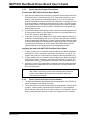
The MCP1630 Dual Buck Demo Board is used to evaluate the Microchip MCP1630
analog, high-speed Pulse Width Modulator (PWM) used in a dual synchronous, buck
regulator, power-converter application. The evaluation board is a complete,
stand-alone, dual-output, dc-dc converter with +12V input, adjustable dual output at
20A per output.
This chapter also covers the following topics:
• What is the MCP1630 Dual Buck Demo Board?
• What the MCP1630 Dual Buck Demo Board kit includes.
CS
60T
+VIN
1T
+
VOUT1
CS
+VCC
MCP1630
COMP
FB
CS
OSC
LBUCK
PWM
Synch
Gate
Drive
VOUT1
+
COUT1
Temp
Sense
#1
VREF
+
–
Active-Filter
MCP6231 SC-70
Temperature sensor located
close to the power switches of
each channel
PIC16F684
Temp
Sense
#2
VOUT2
CS
MCP1630
COMP
FB
CS
OSC
LBUCK
PWM
Synch
Gate
Drive
VOUT2
+
COUT2
VREF
“Bit bang reference”
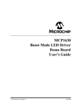
FIGURE 1-1:
+
–
Active-Filter
MCP6231 SC-70
Dual Buck Demo Board Block Diagram.
© 2005 Microchip Technology Inc.
DS51531A-page 5
MCP1630 Dual Buck Demo Board User’s Guide
1.2
WHAT IS THE MCP1630 DUAL BUCK DEMO BOARD?
The MCP1630 Dual Buck Demo Board is a complete, stand-alone, dual-output power
supply capable of 20A per output, powered from a +12V input source. This board
utilizes Microchip’s MCP1630 (high-speed PIC ® MCU PWM MSOP8), PIC16F684
(MCU Flash TSSOP14), MCP6231U (Op Amp SC-70) and TC6501 (Temperature
Switch SOT23A-5). The input voltage range for the demo board is +9.0V to +13.5V.
Both adjustable regulated outputs are capable of 20A.
Input terminals are provided to apply an intput voltage to the power supply. Output
terminals are also provided as a way to connect the 20A outputs to a load.
1.3
WHAT THE MCP1630 DUAL BUCK DEMO BOARD KIT INCLUDES
This MCP1630 Dual Buck Demo Board Kit includes:
• The MCP1630 Dual Buck Demo Board
• MCP1630 Dual Buck Demo Board User’s Guide (DS51531)
• MCP1630 Data Sheet (DS21896)
DS51531A-page 6
© 2005 Microchip Technology Inc.
MCP1630 DUAL BUCK DEMO
BOARD USER’S GUIDE
Chapter 2. Installation and Operation
2.1
INTRODUCTION
The MCP1630 Dual Buck Demo Board demonstrates Microchip’s MCP1630
high-speed PWM, used in an adjustable, dual-output, buck regulator application. The
MCP1630 is a high-speed, microcontroller-adaptable, PWM that, when used in
conjunction with a microcontroller, will control the power system duty cycle to provide
output voltage regulation. The PIC16F684 microcontroller can be used to regulate
output voltage or current, switching frequency and setting maximum duty cycle. The
MCP1630 generates duty cycle, provides fast overcurrent protection and utilizes
variable external inputs. External signals include the input oscillator and the reference
voltage. The power train signals include the current sense and the feedback voltage.
The output signal is a square-wave pulse. The power train used for the MCP1630 Dual
Buck Demo Board is a dual synchronous buck regulator.
2.2
FEATURES
The MCP1630 Dual Buck Demo Board has the following features:
•
•
•
•
•
•
•
•
•
2.3
Input Voltage Range: +9.0V to +13.5V
Adjustable Output Voltage Capable of Calibration
Sequencing or Tracking Outputs
Outputs are180° out of phase, each capable of 20A
Independent Overcurrent Protection
Independent Overtemperature Protection
Input Overvoltage and Undervoltage Lockout (UVLO)
Power Good Indication (LED) with Adjustable Delay
Switching Frequency Dithering
GETTING STARTED
The MCP1630 Dual Buck Demo Board is fully assembled and tested over its range of
input voltage, output voltage and output current. This board requires the use of an
external input voltage source (+9.0V to +13.5V) and external load (electronic or
resistive).
Note:
© 2005 Microchip Technology Inc.
It is recommended that a minimum 300 linear feet per minute of airflow
blown directly across the board to cool the power dissipating components
when operating above 10A loads.
DS51531A-page 7
MCP1630 Dual Buck Demo Board User’s Guide
2.3.1
Power Input and Output Connections
Powering the MCP1630 Dual Buck Demo Board.
1. Apply the input voltage to the connector (J3) provided. Connect the positive side
of the input source (+) to the test point (J3-1). Connect the negative (or return
side (-)) of the input source to the GND terminal (J3-2). J3 is the center two
position terminal block located on the left side of the board. A 14-gauge wire size
is recommended for evaluating the board at 20A per output. The power supply
input voltage must be in the specified operating range for the board to operate.
An undervoltage lockout circuit prevents the converter from running when the
input voltage is too low.
2. An on/off push-button switch (SW3) is used to turn the converter outputs on and
off. During normal power-up, the outputs are turned on by pressing SW3 once.
To turn the outputs off, press SW3 again.
3. In the event of a fault, (input voltage out-of-range, output voltage out-of-range or
power train overtemperature), both VOUT1 and VOUT2 will shut down, indicated
by the D1 power good LED flashing. To restart, the input voltage must be brought
to 0V and raised back to the specified input voltage range of the converter prior
to pressing the on/off button. A solid D1 power good LED indicates that the
regulator outputs are operating properly at their programmed values.
Applying the load to the MCP1630 Dual Buck Demo Board.
1. To apply a load to VOUT1 of the MCP1630 Dual Buck Demo Board, the positive
side of the VO1 load (+) should be connected to the terminal +VO1 (J2-2). The
negative side of the VO1 load should be connected to the terminal GND (J2-1).
2. To apply a load to VOUT2 of the MCP1630 Dual Buck Demo Board, the positive
side of the VO2 load (+) should be connected to the terminal +VO2 (J4-2). The
negative side of the VO2 load should be connected to the terminal GND (J4-1).
3. Outputs VO1 and VO2 are independent of each other and are loaded separately.
Both outputs have independent over current protection, overtemperature and
short-circuit protection.
Note:
2.3.2
The maximum rated load is 20A per output. When loading the board over
10A, airflow is necessary to prevent the overtemperature protection
circuitry from automatically turing off the power train that has the
overtemperature condition.
Power Present and Power Good Indication
1. The MCP1630 Dual Buck Demo Board has two status LED’s. One LED (D3) is
used to determine if input voltage is present.
2. The second LED (D1) is used for fault and power good indication. During normal
operation, if both regulator outputs are within regulation, D1 is illuminated to
provide indication that power is good. If either output is out of regulation, D1 will
blink, providing indication that one or both of the outputs are not in regulation.
DS51531A-page 8
© 2005 Microchip Technology Inc.
MCP1630 Dual Buck Demo Board User’s Guide
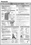
2.3.3
Programming
1. The MCP1630 Dual Buck Demo Board can be programmed to calibrate VOUT1,
VOUT2, output sequencing or tracking and switching frequency dithering on or off.
2. To enter the programming mode, apply input voltage within the specified
operating range (9V to 13.5V). Press and hold the M (SW1) button. While still
holding the M button, press and release the on/off (SW3) button. The flashing
rate of LED D1 should increase, indicating Programming mode.
3. Once in Programming mode, the first variable to set is VOUT1. Press the select S
button to increase VOUT1. Keep pressing the S button to increase VOUT1 until it
wraps around to the minimum setting.
Note:
The range of VOUT1 is controlled by the value of fixed resistors R34, R35 and
R10. The range of VOUT1 is typically from 2.42V (minimum) to 3.39V
(maximum).
4. Press M once to select VOUT2. VOUT2 in increased by pressing the S button
similar to setting VOUT1.
Note:
The range of VOUT2 is controlled by the value of fixed resistors R14, R15 and
R42. The range of VOUT2 is typically from 1.22V (minimum) to 2.3V
(maximum).
5. Press M once to select between output sequencing or tracking. D1 flashing
indicates that sequencing is selected. Press M to change from sequencing to
tracking, or from tracking to sequencing.
6. Press M once to select between frequency dithering on and frequency dithering
off. D1 flashing indicates that frequency dithering is selected.
7. By pressing and holding the M button, the selected settings will be programmed.
The next power-up cycle for the converter will return to the programmed settings.
B OAR D
Mode
Select
On/Off
FIGURE 2-1:
© 2005 Microchip Technology Inc.
Mode, Select and On/Off Switch Location.
DS51531A-page 9
MCP1630 Dual Buck Demo Board User’s Guide
NOTES:
DS51531A-page 10
© 2005 Microchip Technology Inc.
MCP1630 DUAL BUCK DEMO
BOARD USER’S GUIDE
Appendix A. Schematic and Layouts
A.1
INTRODUCTION AND HIGHLIGHTS
This appendix contains the following schematics and layouts for the MCP1630 Dual
Buck Demo Board:
•
•
•
•
•
•
Board Schematic
Board Outline
Board - Top Layer
Board - Mid Layer 1
Board - Mid Layer 2
Board - Bottom Layer
© 2005 Microchip Technology Inc.
DS51531A-page 11
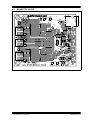
MCP1630 DUAL BUCK DEMO BOARD USER’S GUIDE
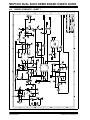
BOARD SCHEMATIC - SHEET 1
S
U3
G
G
S
D
D
A.2
DS51531A-page 12
© 2005 Microchip Technology Inc.
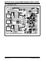
BOARD SCHEMATIC - SHEET 2
© 2005 Microchip Technology Inc.
S
D
G
G
S
D
A.3
DS51531A-page 13
MCP1630 DUAL BUCK DEMO BOARD USER’S GUIDE
A.4
BOARD OUTLINE
0.175
BOARD
0.175
DS51531A-page 14
© 2005 Microchip Technology Inc.
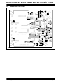
A.5
BOARD TOP LAYER
BOARD
© 2005 Microchip Technology Inc.
DS51531A-page 15
MCP1630 DUAL BUCK DEMO BOARD USER’S GUIDE
A.6
BOARD MID-LAYER 1
BOARD
DS51531A-page 16
© 2005 Microchip Technology Inc.
A.7
BOARD MID-LAYER 2
BOARD
MIDLAYER2
© 2005 Microchip Technology Inc.
DS51531A-page 17
MCP1630 DUAL BUCK DEMO BOARD USER’S GUIDE
A.8
BOARD BOTTOM LAYER
DS51531A-page 18
© 2005 Microchip Technology Inc.
MCP1630 DUAL BUCK DEMO
BOARD USER’S GUIDE
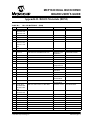
Appendix B. Bill-Of-Materials (BOM)
TABLE B-1:
Qty
9
BILL-OF-MATERIALS
Reference
(BOM)
Description
ECJ-1VB1A105K
CAP 1500PF 50V CERAMIC NPO 0603
CAP 220UF 4V AO X7343
CAP 9.0PF 50V CERAMIC NPO 0603
CAP .10UF 10V CERAMIC X7R 0603
Panasonic - ECG
Kemet Electronics®
Panasonic - ECG
Kemet Electronics
ECJ-1VB1H152K
A700X227M004ATE015
ECJ-1VC1H090D
C0603C104K8RACTU
CAP 4.7UF 10V CERAMIC X5R 0603
CAP .22UF 10V CERAMIC X5R 0603
CAP 22UF 16V CERAMIC X5R 1210
Panasonic - ECG
Panasonic - ECG
TDK Electronics
Corporation
ECJ-1VB0J475M
ECJ-1VB1A224K
C3225X5R1C226M
2
2
2
1
2
C21, C22
C23, C39
C24, C40
C28
D1, D3
CAP DNP0603
CAP 33PF 50V CERAMIC NPO 0603
CAP 1000PF 50V CERAMIC NPO 0603
CAP CERAMIC 18PF 50V 0603 SMD
LED 660NM SUPER RED DIFF 0603SMD
1
1
D2
J1
3
2
2
J2, J3, J4
L1, L2
Q1, Q4
2
Q2, Q3
10
R1, R6, R12,
R17, R20, R23,
R27, R31, R43,
R52
R2, R19, R22,
R25, R29, R50
R3, R24
R4, R46
R5, R18
R7, R9, R16, R21
R8, R45
R10, R15
R11, R39, R44
R13
2
2
2
4
2
2
3
1
Part Number
Panasonic - ECG
2
2
2
6
®
CAP 1.0UF 10V CERAMIC X5R 0603
C1, C9, C16,
C25, C26, C29,
C33, C36, C38
C2, C4, C20, C37
C3, C15
C5, C19
C6, C7, C11,
C14, C17, C27,
C30, C31, C32,
C34
C8, C18
C10, C35
C12, C13
4
2
2
10
Manufacturer
Panasonic - ECG
Panasonic - ECG
Panasonic - ECG
Lumex® Opto/
Components Inc.
DIODE SCHOTTKY 25V 1.0A MINI-2P
Panasonic - SSG
CONN MOD JACK 6-6 R/A PCB 50AU
AMP/Tyco
Electronics
CONN TERM BLOCK 2POS 5MM PCB
Phoenix Contact®
HIGH CURRENT SMT 1UH INDUCTORS Cooper Electronics
N-CHANNEL MOSFET DPAK
Fairchild®
Semiconductor
N-CHANNEL MOSFET DPAK
Fairchild
Semiconductor
RES 10.0 OHM 1/16W 1% 0603 SMD
Panasonic - ECG
ECJ-1VC1H330J
ECJ-1VC1H102J
ECJ-1VC1H180J
SML-LX0603SRW-TR
MA2YD2300L
555165-1
1715022
HC1-1R1
FDD6676S
FDD6670A
ERJ-3EKF10R0V
RES DNP0603
RES 3.30 OHM 1/4W 1% 1206 SMD
RES 1.00K OHM 1/16W 1% 0603 SMD
RES 221 OHM 1/16W 1% 0603 SMD
RESISTOR 1.0 OHM 1/10W 5% 0603
RES 14.7K OHM 1/16W 1% 0603 SMD
RES 24.9K OHM 1/16W 1% 0603 SMD
RES 7.87K OHM 1/16W 1% 0603 SMD
RES 4.99K OHM 1/16W 1% 0603 SMD
© 2005 Microchip Technology Inc.
Yageo America
Panasonic - ECG
Panasonic - ECG
Panasonic - ECG
Panasonic - ECG
Panasonic - ECG
Panasonic - ECG
Panasonic - ECG
9C12063A3R30FGHFT
P1.00KHCT-ND
ERJ-3EKF2210V
ERJ-3GEYJ1R0V
ERJ-3EKF1472V
ERJ-3EKF2492V
ERJ-3EKF7871V
ERJ-3EKF4991V
DS51531A-page 19
MCP1630 Dual Buck Demo Board User’s Guide
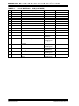
TABLE B-1:
BILL-OF-MATERIALS
(BOM) (CONTINUED)
Qty
Reference
1
3
2
1
1
3
2
2
1
1
1
3
1
1
R14
R26, R40, R51
R28, R49
R30
R32
R33, R36, R48
R34, R41
R35, R42
R37
R38
R47
SW1, SW2, SW3
T1
TP6
RES 22.1K OHM 1/16W 1% 0603 SMD
RES 3.01K OHM 1/16W 1% 0603 SMD
RES 30.1K OHM 1/16W 1% 0603 SMD
RES 4.75K OHM 1/16W 1% 0603 SMD
RES 2.0K OHM 1/10W 5% 0603 SMD
RES 100K OHM 1/16W 1% 0603 SMD
RES 15.0K OHM 1/16W 1% 0603 SMD
RES 10.0K OHM 1/16W 1% 0603 SMD
RES 2.2 OHM 1/4W 1% 1206 SMD
RES 332 OHM 1/16W 1% 0603 SMD
RES 2.21K OHM 1/16W 1% 0603 SMD
SWITCH TACT 6MM 260GF SMT
SMD Current Sense Transformer
PC TEST POINT COMPACT SMT
2
U1, U8
High Speed Analog PWM MSOP8
2
U2, U7
2
U3, U6
Intersil ISL6207 MOSFET Driver SOIC8
Package
5 Lead SC70 OP AMP
1
U4
General Purpose Low Current Regulator
1
U5
IC PIC® MCU FLASH 2KX14 14TSSOP
2
U9, U10
MCP6501 TEMPERATURE SWITCH
75°C
DS51531A-page 20
Description
Manufacturer
Part Number
Panasonic - ECG
Panasonic - ECG
Panasonic - ECG
Panasonic - ECG
Panasonic - ECG
Panasonic - ECG
Panasonic - ECG
Panasonic - ECG
Panasonic - ECG
Panasonic - ECG
Panasonic - ECG
E-Switch Inc.
Datatronics™
Keystone
Electronics
Microchip
Technology Inc.
Intersil®
ERJ-3EKF2212V
ERJ-3EKF3011V
ERJ-3EKF3012V
ERJ-3EKF4751V
ERJ-3GEYJ202V
ERJ-3EKF1003V
ERJ-3EKF1502V
ERJ-3EKF1002V
ERJ-8RQF2R2V
ERJ-3EKF3320V
P2.21KHCT-ND
TL3301NF260QG
CT323-060
5016
Microchip
Technology Inc.
Texas
Instruments™
Microchip
Technology Inc.
Microchip
Technology Inc.
MCP6231U
MCP1630I
ISL6207CBZ
UA78L05ACPK
PIC16F684-I/ST
TC6501P075VCTTR
© 2005 Microchip Technology Inc.
MCP1630 DUAL BUCK DEMO
BOARD USER’S GUIDE
Appendix C. Evaluation Board Firmware
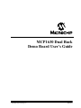
C.1
DEVICE FIRMWARE
For the latest version of the MCP1630 Dual Buck Demo Board firmware, visit the
Microchip web site at www.microchip.com.
Power-Up
Initialize:
Ports, Clocks, A/D,
PWM, IIC and
Interrupts
VIN ok?
No
Yes
No
ON
Detected?
Yes
Yes
Mode
Pressed?
LED Flashing
No
Start Converter
Using programmed
settings
Yes
Turn VOUT1 On
Mode
Pressed?
Fault
Detected
Increment
PWM
No
Yes
Off
Detected
Yes
No
Yes
No
Set
Pressed?
No
Set up VOUT2
Shutdown Converter
Flash LED
Select
Sequencing
or Tracking
End
Select Frequency
Dithering On or
Off
Yes
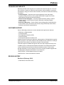
FIGURE C-1:
© 2005 Microchip Technology Inc.
Setup
Complete
No
Firmware Flowcharge - Page 1.
DS51531A-page 21
WORLDWIDE SALES AND SERVICE
AMERICAS
ASIA/PACIFIC
ASIA/PACIFIC
EUROPE
Corporate Office
2355 West Chandler Blvd.
Chandler, AZ 85224-6199
Tel: 480-792-7200
Fax: 480-792-7277
Technical Support:
http://support.microchip.com
Web Address:
www.microchip.com
Australia - Sydney
Tel: 61-2-9868-6733
Fax: 61-2-9868-6755
India - Bangalore
Tel: 91-80-2229-0061
Fax: 91-80-2229-0062
China - Beijing
Tel: 86-10-8528-2100
Fax: 86-10-8528-2104
India - New Delhi
Tel: 91-11-5160-8631
Fax: 91-11-5160-8632
Austria - Weis
Tel: 43-7242-2244-399
Fax: 43-7242-2244-393
Denmark - Ballerup
Tel: 45-4450-2828
Fax: 45-4485-2829
China - Chengdu
Tel: 86-28-8676-6200
Fax: 86-28-8676-6599
Japan - Kanagawa
Tel: 81-45-471- 6166
Fax: 81-45-471-6122
France - Massy
Tel: 33-1-69-53-63-20
Fax: 33-1-69-30-90-79
China - Fuzhou
Tel: 86-591-8750-3506
Fax: 86-591-8750-3521
Korea - Seoul
Tel: 82-2-554-7200
Fax: 82-2-558-5932 or
82-2-558-5934
Germany - Ismaning
Tel: 49-89-627-144-0
Fax: 49-89-627-144-44
Atlanta
Alpharetta, GA
Tel: 770-640-0034
Fax: 770-640-0307
Boston
Westford, MA
Tel: 978-692-3848
Fax: 978-692-3821
Chicago
Itasca, IL
Tel: 630-285-0071
Fax: 630-285-0075
Dallas
Addison, TX
Tel: 972-818-7423
Fax: 972-818-2924
Detroit
Farmington Hills, MI
Tel: 248-538-2250
Fax: 248-538-2260
Kokomo
Kokomo, IN
Tel: 765-864-8360
Fax: 765-864-8387
China - Hong Kong SAR
Tel: 852-2401-1200
Fax: 852-2401-3431
China - Shanghai
Tel: 86-21-5407-5533
Fax: 86-21-5407-5066
China - Shenyang
Tel: 86-24-2334-2829
Fax: 86-24-2334-2393
China - Shenzhen
Tel: 86-755-8203-2660
Fax: 86-755-8203-1760
China - Shunde
Tel: 86-757-2839-5507
Fax: 86-757-2839-5571
Singapore
Tel: 65-6334-8870
Fax: 65-6334-8850
Taiwan - Kaohsiung
Tel: 886-7-536-4818
Fax: 886-7-536-4803
Taiwan - Taipei
Tel: 886-2-2500-6610
Fax: 886-2-2508-0102
Italy - Milan
Tel: 39-0331-742611
Fax: 39-0331-466781
Netherlands - Drunen
Tel: 31-416-690399
Fax: 31-416-690340
England - Berkshire
Tel: 44-118-921-5869
Fax: 44-118-921-5820
Taiwan - Hsinchu
Tel: 886-3-572-9526
Fax: 886-3-572-6459
China - Qingdao
Tel: 86-532-502-7355
Fax: 86-532-502-7205
Los Angeles
Mission Viejo, CA
Tel: 949-462-9523
Fax: 949-462-9608
San Jose
Mountain View, CA
Tel: 650-215-1444
Fax: 650-961-0286
Toronto
Mississauga, Ontario,
Canada
Tel: 905-673-0699
Fax: 905-673-6509
10/20/04
DS51531A-page 22
© 2004 Microchip Technology Inc.