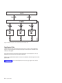
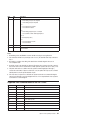
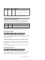
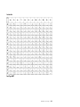
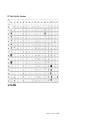
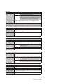
1
Compuprint 4247 Serial Matrix Printers Compuprint 4247 Model X03/Z03 Printers: Programmer Manual MAN10299.00.00 Before using this information and the product it supports, read the information in “Notices” on page 357. First edition (October 2011) This edition applies to the Compuprint 4247 X03-Z03 printers and to all subsequent releases and modifications until otherwise indicated in new edition. Internet Visit our home page: http://www.compuprint.com You can send comments by e-mail to : [email protected] or by mail to: Compuprint s.r.l. Via Lombardore 282 10040 Leinì (Turin) ITALY ii Programmer Manual Contents Figures . . . . . . . . . . . . . . . . . . . . . . . . . . . . . . . . . . . . xiii Tables . . . . . . . . . . . . . . . . . . . . . . . . . . . . . . . . . . . . xv The 4247 Model X03/Z03 Serial Matrix Printers Printer description . . . . . . . . . . . . Print speeds . . . . . . . . . . . . . Paper paths . . . . . . . . . . . . . Print qualities . . . . . . . . . . . . Printer interfaces . . . . . . . . . . . Printer datastream emulations . . . . . . How to Use This Manual. . . . . . . . . . . . . . . . . . . . . . . . . . . . . . . . . . . . . . . . . . . . . . . . . . Chapter 1. Personal Printer Data Stream (PPDS) . . . . Print Job Processing . . . . . . . . . . . . . . . . Page Printing Concept . . . . . . . . . . . . . . . Page Presentation . . . . . . . . . . . . . . . . Graphic and Control Character Sequences . . . . . . . PPDS Compatibility . . . . . . . . . . . . . . . . One-Byte Controls . . . . . . . . . . . . . . . . Null (NUL) . . . . . . . . . . . . . . . . . . Bell (BEL). . . . . . . . . . . . . . . . . . . Backspace (BS) . . . . . . . . . . . . . . . . Horizontal Tab (HT) . . . . . . . . . . . . . . . Line Feed (LF) . . . . . . . . . . . . . . . . . Vertical Tab (VT) . . . . . . . . . . . . . . . . Form Feed (FF) . . . . . . . . . . . . . . . . Carriage Return (CR) . . . . . . . . . . . . . . Shift Out (SO) / Double-Wide Print . . . . . . . . . Shift In (SI) / Condensed Print . . . . . . . . . . . Device Control 1 (DC1) / Select . . . . . . . . . . Device Control 2 (DC2) / Select . . . . . . . . . . Device Control 3 (DC3) / Select . . . . . . . . . . Device Control 4 (DC4) / Select . . . . . . . . . . Cancel (CAN) . . . . . . . . . . . . . . . . . Escape (ESC) . . . . . . . . . . . . . . . . . Space . . . . . . . . . . . . . . . . . . . . Escape Sequence Controls . . . . . . . . . . . . . Null (ESC NUL) . . . . . . . . . . . . . . . . Bell (ESC BEL). . . . . . . . . . . . . . . . . Backspace (ESC BS) . . . . . . . . . . . . . . Horizontal Tab (ESC HT) . . . . . . . . . . . . . Line Feed (ESC LF) . . . . . . . . . . . . . . . Vertical Tab (ESC VT) . . . . . . . . . . . . . . Form Feed (ESC FF) . . . . . . . . . . . . . . Carriage Return (ESC CR) . . . . . . . . . . . . Shift Out (ESC SO) / Doube-Wide Print . . . . . . . Shift In (ESC SI) / Condensed Print . . . . . . . . . Device Control 1 (ESC DC1 / Select) . . . . . . . . Device Control 2 (ESC DC2) / Select 10 CPI . . . . . Device Control 3 (ESC DC3) / Deselect . . . . . . . Device Control 4 (ESC DC4) / Cancel Double-Wide Print . Cancel (ESC CAN) . . . . . . . . . . . . . . . . . . . . . . . . . . . . . . . . . . . . . . . . . . . . . . . . . . . . . . . . . . . . . . . . . . . . . . . . . . . . . . . . . . . . . . . . . . . . . . . . . . . . . . . . . . . . . . . . . . . . . . . . . . . . . . . . . . . . . . . . . . xvii . xvii . xvii . xvii . xviii . xviii . xviii . xix . . . . . . . . . . . . . . . . . . . . . . . . . . . . . . . . . . . . . . . . . . . . . . . . . . . . . . . . . . . . . . . . . . . . . . . . . . . . . . . . . . . . . . . . . . . . . . . . . . . . . . . . . . . . . . . . . . . . . . . . . . . . . . . . . . . . . . . . . . . . . . . . . . . . . . . . . . . . . . . . . . . . . . . . . . . . . . . . . . . . . . . . . . . . . . . . . . . . . . . . . . . . . . . . . . . . . . . . . . . . . . . . . . . . . . . . . . . . . . . . . . . . . . . . . . . . . . . . . . . . . . . . . . . . . . . . . . . . . . . . . . . . . . . . . . . . . . . . . . . . . . . . . . . . . . . . . . . . . . . . . . . . . . . . . . . . . . . . . . . . . . . . . . . . . . . . . . . . . . . . . . . . . . . . . . . . . . . . . . . . . . . . . . . . . . . . . . . . . . . . . . . . . . . . . . . . . . . . . . . . . . . . . . . . . . . . . . . . . . . . . . . . . . . . . . . . . . . . . . . . . . . . . . . . . . . . . . . . . . . . . . . . . . . . . . . . . . . . . . . . . . . . . . . . . . . . . . . . . . . . . . . . . . . . . . . . . . . . . . . . . . . . . . . . . . . . . . . . . . . . . . . . . . . . . . . . . . . . . . . . . . . . . . . . . . . 1 . 1 . 1 . 1 . 3 . 4 . 4 . 4 . 4 . 5 . 5 . 5 . 5 . 5 . 5 . 6 . 6 . 6 . 6 . 6 . 7 . 7 . 7 . 7 . 7 . 9 . 9 . 9 . 9 . 9 . 10 . 10 . 10 . 10 . 10 . 11 . 11 . 11 . 11 . 11 iii Auto Underscore (ESC -) . . . . . . . . . . . . Set 1/8 Inch Line Spacing (ESC 0) . . . . . . . . . Set 7/72 Inch Line Spacing (ESC 1) . . . . . . . . Invoke Text Line Spacing (ESC 2) . . . . . . . . . Set Graphics Line Spacing (ESC 3) . . . . . . . . . Set Top of Form (ESC 4). . . . . . . . . . . . . Set Auto Line Feed (ESC 5) . . . . . . . . . . . Select PC Character Set 2 (ESC 6) . . . . . . . . . Select PC Character Set 1 (ESC 7) . . . . . . . . . Set 12 CPI (ESC :) . . . . . . . . . . . . . . . Unidirectional Printing (ESC <) . . . . . . . . . . Character Font Image Download (ESC =) . . . . . . Select n/72 Inch Line Spacing (ESC A) . . . . . . . Set Vertical Tabs (ESC B) . . . . . . . . . . . . Set Page Length (ESC C) . . . . . . . . . . . . Set Horizontal Tabs (ESC D) . . . . . . . . . . . Begin Emphasized Print (ESC E). . . . . . . . . . End Emphasized Print (ESC F) . . . . . . . . . . Begin Double-Strike Print (ESC G) . . . . . . . . . End Double-Strike Print (ESC H) . . . . . . . . . . Change Font (ESC I) . . . . . . . . . . . . . . Relative Move Baseline (ESC J) . . . . . . . . . . Normal Density Bit Image Graphics (ESC K) . . . . . Dual Density Bit Image Graphics Type 1 (ESC L). . . . Begin Skip Perforation (ESC N) . . . . . . . . . . End Skip Perforation (ESC O) . . . . . . . . . . . Proportional Space Mode (ESC P) . . . . . . . . . Deselect on Positive Query Reply (ESC Q) . . . . . . Set Default Tabs (ESC R) . . . . . . . . . . . . Begin Subscript/Superscript (ESC S) . . . . . . . . End Subscript/Superscript (ESC T) . . . . . . . . . Set Print Direction (ESC U) . . . . . . . . . . . . Double-Wide Continuous Mode (ESC W) . . . . . . . Set Horizontal Margins (ESC X) . . . . . . . . . . Dual Density Bit Image Graphics Type 2 (ESC Y) . . . High Density Bit Image Graphics (ESC Z) . . . . . . Print All Characters (ESC \) . . . . . . . . . . . . Reverse Line Feed (ESC ]) . . . . . . . . . . . . Print Single Character (ESC ^) . . . . . . . . . . Continuous Overscore (ESC _) . . . . . . . . . . Relative Move Right (ESC d) . . . . . . . . . . . Relative Move Left (ESC e) . . . . . . . . . . . . Select Line Scoring (ESC [ -) . . . . . . . . . . . Set Presentation Highlight (SPH) (ESC [ @) . . . . . Set Font Global (SFG) (ESC [ I) . . . . . . . . . . Set Initial Conditions (SIC) (ESC [ K) . . . . . . . . Select Code Page (SCP) (ESC [ T) . . . . . . . . . Set Print Quality (SPQ) (ESC [ d) . . . . . . . . . 4247 Commands . . . . . . . . . . . . . . . . Select EAN-8 Bar Code (DC4 DC4 ESC ! NN 1 PP EM) . Select EAN-13 Bar Code (DC4 DC4 ESC ! NN 2 PP EM) Select UPC-A Bar Code (DC4 DC4 ESC ! NN 3 PP EM) . Select MSI Bar Code (DC4 DC4 ESC ! NN 4 PP EM) . . Select UPC-E Bar Code (DC4 DC4 ESC ! NN 5 PP EM) . Select UPC 2-Digit Bar Code (Magazine) (DC4 DC4 ESC ! Select UPC 5-Digit Bar Code (Magazine) (DC4 DC4 ESC ! iv Programmer Manual . . . . . . . . . . . . . . . . . . . . . . . . . . . . . . . . . . . . . . . . . . . . . . . . . . . . . . . . . . . . . . . . . . . . . . . . . . . . . . . . . . . . . . . . . . . . . . . . . . . . . . . . . . . . . . . . . . . . . . . . . . . . . . . . . . . . . . . . . . . . . . . . . . . . . . . . . . . . . . . . . . . . . . . . . . . . . . . . . . . . . . . . . . . . . . . . . . . . . . . . . . . . . . . . . . . . . . . . . . . . . . . . . . . . . . . . . . . . . . . . . . . . . . . . . . . . . . . . . . . . . . . . . . . . . . . . . . . . . . . . . . . . . . . . . . . . . . . . . . . . . . . . . . . . . . . . . . . . . . . . . . . . NN 6 PP EM) NN 7 PP EM) . . . . . . . . . . . . . . . . . . . . . . . . . . . . . . . . . . . . . . . . . . . . . . . . . . . . . . . . . . . . . . . . . . . . . . . . . . . . . . . . . . . . . . . . . . . . . . . . . . . . . . . . . . . . . . . . . . . . . . . . . . . . . . . . . . . . . . . . . . . . . . . . . . . . . . . . . . . . . . . . . . . . . . . . . . . . . . . . . . . . . . . . . . . . . . . . . . . . . . . . . . . . . . . . . . . . . . . . . . . . . . . . . . . . . . . . . . . . . . . . . . . . . . . . . . . . . . . . . . . . . . . . . . . . . . . . . . . . . . . . . . . . . . . . . . . . . . . . . . . . . . . . . . . . . . . . . . . . . . . . . . . . . . . . . . . . . . . . . . . . . . . . . . . . . . . . . . . . . . . . . . . . . . . . . . . . . . . . . . . . . . . . . . . . . . . . . . . . . . . . . . . . . . . . . . . . . . . . . . . . . . . . . . . . . . . . . . . . . . . . . . . . . . . . . . . . . . . . . . . . . . . . . . . . . . . . . . . . . . . . . . . . . . . . . . . . . . . . . . . . . . . . . . . . . . . . . . . . . . . . . . . . . . . . . . . . . . . . . . . . . . . . . . . . . . . . . . . . . . . . 12 12 12 12 12 13 13 13 13 13 13 14 15 15 15 16 16 16 16 16 16 17 18 18 18 18 19 19 19 19 20 20 20 20 21 21 21 21 22 22 22 22 22 23 23 24 26 27 28 29 29 29 30 30 30 31 Select 2 of 5 INTERLEAVED Bar Code (DC4 DC4 ESC ! NN 17 PP EM) . . . . . Select 2 of 5 INDUSTRIAL Bar Code (DC4 DC4 ESC ! NN 18 PP EM). . . . . . Select 2 of 5 MATRIX Bar Code (DC4 DC4 ESC ! NN 19 PP EM) . . . . . . . Select CODE 3 of 9 Bar Code (DC4 DC4 ESC ! NN 20 PP EM) . . . . . . . . Select CODABAR Bar Code (DC4 DC4 ESC ! NN 22 PP EM) . . . . . . . . . Select CODE 128 Bar Code (DC4 DC4 ESC ! NN 23 PP EM) . . . . . . . . . Select POSTNET Bar Code (DC4 DC4 ESC ! NN 24 PP EM) . . . . . . . . . Print Bar Code Selection (DC4 DC4 ESC ( GS {N1} {DATA1} GS {N2} {DATA2} EM). Reinitialize Printer (DC4 DC4 ESC @). . . . . . . . . . . . . . . . . . Set Vertical Spacing n/144 Inch (DC4 DC4 ESC 1 NN) . . . . . . . . . . . Set Vertical Spacing 12 Lines/30mm (DC4 DC4 ESC 3 1) . . . . . . . . . . Set Vertical Spacing 3 Lines/30mm (DC4 DC4 ESC 3 3) . . . . . . . . . . . Set Vertical Spacing 4 Lines/30mm (DC4 DC4 ESC 3 4) . . . . . . . . . . . Set Vertical Spacing 6 Lines/30mm (DC4 DC4 ESC 3 6) . . . . . . . . . . . Set Vertical Spacing 8 Lines/30mm (DC4 DC4 ESC 3 8) . . . . . . . . . . . Eject Single Sheet or Form Feed (DC4 DC4 ESC 5) . . . . . . . . . . . . Set 15, 17.1, 20 CPI (DC4 DC4 ESC A) . . . . . . . . . . . . . . . . . Load or Park Fanfold from a Rear Path (DC4 DC4 ESC N) . . . . . . . . . . Load or Park Fanfold from a Front Path (DC4 DC4 ESC T) . . . . . . . . . . Select Emulation (DC4 DC4 ESC Y) . . . . . . . . . . . . . . . . . . Select AFTA in Column (DC4 DC4 ESC Z) . . . . . . . . . . . . . . . . Select Resident Font (DC4 DC4 ESC g) . . . . . . . . . . . . . . . . . Request to Read Configuration (DC4 DC4 ESC h) . . . . . . . . . . . . . Printer Configuration Response (DC4 DC4 ESC h) . . . . . . . . . . . . . Write Configuration Response (DC4 DC4 ESC i) . . . . . . . . . . . . . . Write Configuration Acknowledgement (DC4 DC4 ESC i) . . . . . . . . . . . Select Print Quality (DC4 DC4 ESC p). . . . . . . . . . . . . . . . . . Buffer Terminating Conditions . . . . . . . . . . . . . . . . . . . . . . . . . . . . . . . . . . . . . . . . . . . . . . . . . . . . . . . . . . . . . . . . . . . . . . . . . . . . . . . . . . . . . . . . . . . . . . . . . . . . . . . . . . . . . . . . . . . . . . . . . . . . . . . . . . . . . . . . . . . . . . . . . . . . . . . . . . . . . . . . . . . . . . . . . . . . . . . . . . . . . . . . . . . . . . 31 31 32 32 32 33 33 34 34 34 34 34 35 35 35 35 35 35 36 36 36 36 36 37 37 37 37 38 Chapter 2. Epson FX-1050 Data Stream . . . . . Print Job Processing . . . . . . . . . . . . . Page Printing Concept . . . . . . . . . . . . Page Presentation . . . . . . . . . . . . . . One-Byte Controls . . . . . . . . . . . . . . Null (NUL) . . . . . . . . . . . . . . . . Bell (BEL) . . . . . . . . . . . . . . . . Backspace (BS) . . . . . . . . . . . . . . Horizontal Tab (HT). . . . . . . . . . . . . Line Feed (LF) . . . . . . . . . . . . . . Vertical Tab (VT) . . . . . . . . . . . . . . Form Feed (FF) . . . . . . . . . . . . . . Carriage Return (CR) . . . . . . . . . . . . Shift Out (SO) / Double-Wide Print . . . . . . . Shift In (SI) / Condensed Print . . . . . . . . . Device Control 1 (DC1) / Select . . . . . . . . Device Control 2 (DC2) / Cancel Condensed Print . Device Control 3 (DC3) / Deselect . . . . . . . Device Control 4 (DC4) / Cancel Double-Wide Print . Cancel (CAN) . . . . . . . . . . . . . . . Space (SP). . . . . . . . . . . . . . . . Delete Character (DEL) . . . . . . . . . . . Escape Sequence Controls . . . . . . . . . . . Escape (ESC). . . . . . . . . . . . . . . Null (ESC NUL) . . . . . . . . . . . . . . Bell (ESC BEL) . . . . . . . . . . . . . . Backspace (ESC BS) . . . . . . . . . . . . . . . . . . . . . . . . . . . . . . . . . . . . . . . . . . . . . . . . . . . . . . . . . . . . . . . . . . . . . . . . . . . . . . . . . . . . . . . . . . . . . . . . . . . . . . . . . . . . . . . . . . . . . . . . . . . . . . . . . . . . . . . . . . . . . . . . . . . . . . . . . . . . . . . . . . . . . . . . . . . . . . 39 39 39 39 41 41 41 42 42 42 42 42 42 43 43 43 43 43 44 44 44 44 44 46 46 46 47 Contents v . . . . . . . . . . . . . . . . . . . . . . . . . . . . . . . . . . . . . . . . . . . . . . . . . . . . . . . . . . . . . . . . . . . . . . . . . . . . . . . . . . . . . . . . . . . . . . . . . . . . . . . . . . . . . . . . . . . . . . . . . . . . . . . . . . . . . . . . . . . . . . . . . . . . . . . . . . . . . . . . . . . . . . . . . . . . . . . . . . . . . . . . . . . . . . . . . . . . . . . . . . . . . . . . . . . . . . . . . . . . . . . . . . . . . . . . . . . . . . . . . . . . . . . . . . . . . . . . . . . . . . . . . . . . . . . . . . . . . . . . . . . . . . . . . . . . . . . . . . . . . . . . . . . . . . . . . . . . . . . . . . . . Horizontal Tab (ESC HT) . . . . . . . . . . . . . Line Feed (ESC LF) . . . . . . . . . . . . . . Vertical Tab (ESC VT) . . . . . . . . . . . . . . Form Feed (ESC FF) . . . . . . . . . . . . . . Carriage Return (ESC CR) . . . . . . . . . . . . Shift Out (ESC SO) / Double-Wide Print . . . . . . . Shift In (ESC SI) / Condensed Print . . . . . . . . . Device Control 1 (ESC DC1) / Select . . . . . . . . Device Control 2 (ESC DC2) / Cancel Condensed Print . Device Control 3 (ESC DC3) / Deselect . . . . . . . Device Control 4 (ESC DC4) / Cancel Double-Wide Print . Cancel (ESC CAN) . . . . . . . . . . . . . . . Set Intercharacter Spacing (ESC SP) . . . . . . . . Master Select (ESC !) . . . . . . . . . . . . . . Cancel MSB Control (ESC #) . . . . . . . . . . . Set Absolute Print Position (ESC $) . . . . . . . . . Select User-Defined Set (ESC %) . . . . . . . . . Define User-Defined Characters (ESC &). . . . . . . Select Graphics Mode (ESC *) . . . . . . . . . . Auto Underscore (ESC –) . . . . . . . . . . . . Select Vertical Tab Channel (ESC /). . . . . . . . . Set 1/8 Inch Line Spacing (ESC 0) . . . . . . . . . Set 7/72 Inch Line Spacing (ESC 1) . . . . . . . . Set 1/6 Inch Line Spacing (ESC 2) . . . . . . . . . Set n/216 Inch Line Spacing (ESC 3) . . . . . . . . Select Italic Mode (ESC 4) . . . . . . . . . . . . Cancel Italic Mode (ESC 5) . . . . . . . . . . . . Printable Code Area Expansion (ESC 6) . . . . . . . Cancel Printable Code Area Expansion (ESC 7) . . . . Copy ROM into Ram (ESC : NUL) . . . . . . . . . Select Unidirectional Mode (one line only) (ESC <) . . . Set MSB to 0 (ESC =). . . . . . . . . . . . . . Set MSB to 1 (ESC >). . . . . . . . . . . . . . Reassign Graphics Mode (ESC ?) . . . . . . . . . Initialize Printer (ESC @) . . . . . . . . . . . . Select n/72 Inch Line Spacing (ESC A) . . . . . . . Set Vertical Tabs (ESC B) . . . . . . . . . . . . Set Page Length (ESC C) . . . . . . . . . . . . Set Horizontal Tabs (ESC D) . . . . . . . . . . . Begin Emphasized Print (ESC E). . . . . . . . . . End Emphasized Print (ESC F) . . . . . . . . . . Begin Double-Strike Print (ESC G) . . . . . . . . . End Double-Strike Print (ESC H) . . . . . . . . . . Printable Code Area Expansion (ESC I) . . . . . . . Perform n/216 Inch Line Feed (ESC J) . . . . . . . Select Single Density Graphics Mode (ESC K). . . . . Select Double Density Graphics Mode (ESC L) . . . . Select 12 CPI (ESC M) . . . . . . . . . . . . . Begin Skip Perforation (ESC N) . . . . . . . . . . End Skip Perforation (ESC O) . . . . . . . . . . . Select 10 CPI (ESC P) . . . . . . . . . . . . . Select Right Margin (ESC Q) . . . . . . . . . . . Select Character Set (ESC R) . . . . . . . . . . . Begin Subscript/Superscript (ESC S) . . . . . . . . End Subscript/Superscript (ESC T) . . . . . . . . . Set Print Direction (ESC U) . . . . . . . . . . . . vi Programmer Manual . . . . . . . . . . . . . . . . . . . . . . . . . . . . . . . . . . . . . . . . . . . . . . . . . . . . . . . . . . . . . . . . . . . . . . . . . . . . . . . . . . . . . . . . . . . . . . . . . . . . . . . . . . . . . . . . . . . . . . . . . . . . . . . . . . . . . . . . . . . . . . . . . . . . . . . . . . . . . . . . . . . . . . . . . . . . . . . . . . . . . . . . . . . . . . . . . . . . . . . . . . . . . . . . . . . . . . . . . . . . . . . . . . . . . . . . . . . . . . . . . . . . . . . . . . . . . . . . . . . . . . . . . . . . . . . . . . . . . . . . . . . . . . . . . . . . . . . . . . . . . . . . . . . . . . . . . . . . . . . . . . . . . . . . . . . . . . . . . . . . . . . . . . . . . . . . . . . . . . . . . . . . . . . . . . . . . . . . . . . . . . . . . . . . . . . . . . . . . . . . . . . . . . . . . . . . . . . . . . . . . . . . . . . . . . . . . . . . . . . . . . . . . . . . . . . . . . . . . . . . . . . . . . . . . . . . . . . . . . . . . . . . . . . . . . . . . . . . . . . . . . . . . . . . . . . . . . . . . . . . . . . . . . . . . . . . . . . . . . . . . . . . . . . . . . . . . . . . . . . . . . . . . . . . . . . . . . . . . . . . . . . . . . . . . . . . . . . . . . . . . . . . . . . . . . . . . . . . . . . . . . . . . . . . . . . . . . . . . . . . . . . . . . . . . . . . . . . . . . . . . . . . . . . . . . . . . . . . . . . . . . . . . . . . . . . . . . . . . . . . . . . . . . . . . . . . . . . . . . . . . . . . . . . . . . . . . . . . . . . . . . . . . . . . . . . . . . . . . . . . . . . . . . . . . . . . . . . . . . . . . . . . . . . . . . . . . . . . . . . . . . . . . . . . . . . . . . . . . . . . . . . . . . . . . . . . . . . . . . . . . . . . . . . . . . . . . . . . . . . . . . . . . . . . . . . . . . . . . . . . . . . . . . . . . . . . . . . . 47 47 47 47 48 48 48 48 48 48 49 49 49 49 49 50 50 50 51 51 51 51 52 52 52 52 52 53 53 53 53 53 53 53 54 54 54 55 55 55 55 55 56 56 56 56 56 57 57 57 57 57 57 58 58 58 Double-Wide Continuous Mode (ESC W) . . . . . . . . . . . . . . . . . Dual Density Bit Image Graphics Type 2 (ESC Y) . . . . . . . . . . . . . High Density Bit Image Graphics (ESC Z) . . . . . . . . . . . . . . . . Set Relative Position (ESC \) . . . . . . . . . . . . . . . . . . . . . Set Letter Quality Justification (ESC a) . . . . . . . . . . . . . . . . . Select Vertical Tabs in Channels (ESC b). . . . . . . . . . . . . . . . . Relative Move Right n/120 (ESC d) . . . . . . . . . . . . . . . . . . . Relative Move Left n/120 (ESC e) . . . . . . . . . . . . . . . . . . . Set 15 CPI (ESC g) . . . . . . . . . . . . . . . . . . . . . . . . Feed Paper n/216 Reverse (ESC j) . . . . . . . . . . . . . . . . . . . Select NLQ Font (ESC k) . . . . . . . . . . . . . . . . . . . . . . Set Left Margin (ESC l) . . . . . . . . . . . . . . . . . . . . . . . Turn Proportional Mode On/Off (ESC p) . . . . . . . . . . . . . . . . . Quiet Printing (ESC s). . . . . . . . . . . . . . . . . . . . . . . . Select Character Table (ESC t) . . . . . . . . . . . . . . . . . . . . Double High Printing (ESC w) . . . . . . . . . . . . . . . . . . . . . Select NLQ or DP Print Quality (ESC x) . . . . . . . . . . . . . . . . . 4247 Commands . . . . . . . . . . . . . . . . . . . . . . . . . . Select EAN-8 Bar Code (DC4 DC4 ESC ! NN 1 PP EM) . . . . . . . . . . . Select EAN-13 Bar Code (DC4 DC4 ESC ! NN 2 PP EM) . . . . . . . . . . Select UPC-A Bar Code (DC4 DC4 ESC ! NN 3 PP EM) . . . . . . . . . . . Select MSI Bar Code (DC4 DC4 ESC ! NN 4 PP EM) . . . . . . . . . . . . Select UPC-E Bar Code (DC4 DC4 ESC ! NN 5 PP EM) . . . . . . . . . . . Select UPC 2-Digit Bar Code (Magazine) (DC4 DC4 ESC ! NN 6 PP EM) . . . . Select UPC 5-Digit Bar Code (Magazine) (DC4 DC4 ESC ! NN 7 PP EM) . . . . Select 2 of 5 INTERLEAVED Bar Code (DC4 DC4 ESC ! NN 17 PP EM) . . . . . Select 2 of 5 INDUSTRIAL Bar Code (DC4 DC4 ESC ! NN 18 PP EM). . . . . . Select 2 of 5 MATRIX Bar Code (DC4 DC4 ESC ! NN 19 PP EM) . . . . . . . Select CODE 3 of 9 Bar Code (DC4 DC4 ESC ! NN 20 PP EM) . . . . . . . . Select CODABAR Bar Code (DC4 DC4 ESC ! NN 22 PP EM) . . . . . . . . . Select CODE 128 Bar Code (DC4 DC4 ESC ! NN 23 PP EM) . . . . . . . . . Select POSTNET Bar Code (DC4 DC4 ESC ! NN 24 PP EM) . . . . . . . . . Print Bar Code Selection (DC4 DC4 ESC ( GS {N1} {DATA1} GS {N2} {DATA2} EM). Reinitialize Printer (DC4 DC4 ESC @). . . . . . . . . . . . . . . . . . Set Vertical Spacing n/144 Inch (DC4 DC4 ESC 1 NN) . . . . . . . . . . . Set Vertical Spacing 12 Lines/30mm (DC4 DC4 ESC 3 1) . . . . . . . . . . Set Vertical Spacing 3 Lines/30mm (DC4 DC4 ESC 3 3) . . . . . . . . . . . Set Vertical Spacing 4 Lines/30mm (DC4 DC4 ESC 3 4) . . . . . . . . . . . Set Vertical Spacing 6 Lines/30mm (DC4 DC4 ESC 3 6) . . . . . . . . . . . Set Vertical Spacing 8 Lines/30mm (DC4 DC4 ESC 3 8) . . . . . . . . . . . Eject Single Sheet or Form Feed (DC4 DC4 ESC 5) . . . . . . . . . . . . Set 15, 17.1, 20 CPI (DC4 DC4 ESC A) . . . . . . . . . . . . . . . . . Load or Park Fanfold from a Rear Path (DC4 DC4 ESC N) . . . . . . . . . . Load or Park Fanfold from a Front Path (DC4 DC4 ESC T) . . . . . . . . . . Select Emulation (DC4 DC4 ESC Y) . . . . . . . . . . . . . . . . . . Select AFTA in Column (DC4 DC4 ESC Z) . . . . . . . . . . . . . . . . Select Resident Font (DC4 DC4 ESC g) . . . . . . . . . . . . . . . . . Request to Read Configuration (DC4 DC4 ESC h) . . . . . . . . . . . . . Printer Configuration Response (DC4 DC4 ESC h) . . . . . . . . . . . . . Write Configuration Response (DC4 DC4 ESC i) . . . . . . . . . . . . . . Write Configuration Acknowledgement (DC4 DC4 ESC i) . . . . . . . . . . . Select Print Quality . . . . . . . . . . . . . . . . . . . . . . . . . Buffer Terminating Conditions . . . . . . . . . . . . . . . . . . . . . . Unsupported Command Processing . . . . . . . . . . . . . . . . . . . . Chapter 3. Intelligent Printer Data Stream . . . . . . . . . . . . . . . . . . . . . . . . . . . . . . . . . . . . . . . . . . . . . . . . . . . . . . . . . . . . . . . . . . . . . . . . . . . . . . . . . . . . . . . . . . . . . . . . . . . . . . . . . . . . . . . . . . . . . . . . . . . . . . . . . . . . . . . . . . . . . . . . . . . . . . . . . . . . . . . . . . . . . . . . . . . . . . . . . . . . . . . . . . . . . . . . . . . . . . . . . . . . . . . . . . . . . . . . . . . . . . . . . . . . . . . . . . . . . . . . . . . . . . . . . . . . . . . . . . . . . . . . . . . . . . . . . . . . . . . . . . . . . . . . . . . . . . . . . . . . . . . . . . . . . . . . . . . . . . . . . . . . 59 59 59 60 60 60 60 60 61 61 61 61 61 61 62 62 62 62 63 64 64 64 65 65 65 66 66 66 67 67 67 68 68 69 69 69 69 69 69 70 70 70 70 70 71 71 71 71 71 72 72 72 72 73 . . . . . . . . . . . . . . . . . . . . . . 75 Contents vii Overview . . . . . . . . . . . . . . . Physical Medium. . . . . . . . . . . . . IPDS Coordinate Systems . . . . . . . . . X and Y Medium Coordinate System . . . . Logical Page Layout . . . . . . . . . . I and B Coordinate System . . . . . . . . Processing IPDS Commands . . . . . . . . IPDS Command Format . . . . . . . . . . Acknowledge Requests and Replies . . . . . Acknowledge Reply (ACK) . . . . . . . . Host Acknowledgment Requests . . . . . . Printer Acknowledgment Replies . . . . . . IPDS Data . . . . . . . . . . . . . . . Mixing Rules . . . . . . . . . . . . . . IPDS Operating States . . . . . . . . . . Home State . . . . . . . . . . . . . Page State . . . . . . . . . . . . . . Overlay State . . . . . . . . . . . . . Page Segment State . . . . . . . . . . A Summary of the IPDS States and Commands . A Typical IPDS Command Sequence . . . . . Printer Initialization and Preparation Sequence. Page Segment Sequence . . . . . . . . Overlay Sequence . . . . . . . . . . . Page Sequence . . . . . . . . . . . . Error Handling . . . . . . . . . . . . . . . . . . . . . . . . . . . . . . . . . . . . . . . . . . . . . . . . . . . . . . . . . . . . . . . . . Chapter 4. IPDS Programming Information . . . . IPDS Initialization Defaults . . . . . . . . . . . Parameter Values . . . . . . . . . . . . . Command Format . . . . . . . . . . . . . . Supported IPDS Command Codes for the 4247 Printer Command Function Sets . . . . . . . . . . . Device Control Function Set Commands . . . . . No Operation (NOP) . . . . . . . . . . . . Sense Type and Model (STM) . . . . . . . . Set Home State (SHS) . . . . . . . . . . . Acknowledge Reply (ACK). . . . . . . . . . Load Font Equivalence (LFE) . . . . . . . . Code Page ID Values . . . . . . . . . . . Load Copy Control (LCC) . . . . . . . . . . Logical Page Descriptor (LPD) . . . . . . . . Logical Page Position (LPP) . . . . . . . . . Deactivate Font (DF) . . . . . . . . . . . . End Page (EP) . . . . . . . . . . . . . . End (END) . . . . . . . . . . . . . . . Execute Order Home State (XOH) . . . . . . . Execute Order Any State (XOA). . . . . . . . Text Function Set Commands . . . . . . . . . Load Equivalence (LE) . . . . . . . . . . . Write Text (WT). . . . . . . . . . . . . . Image Function Set Commands. . . . . . . . . Write Image Control (WIC) . . . . . . . . . Write Image (WI) . . . . . . . . . . . . . End (END) . . . . . . . . . . . . . . . Graphics Function Set Commands. . . . . . . . viii Programmer Manual . . . . . . . . . . . . . . . . . . . . . . . . . . . . . . . . . . . . . . . . . . . . . . . . . . . . . . . . . . . . . . . . . . . . . . . . . . . . . . . . . . . . . . . . . . . . . . . . . . . . . . . . . . . . . . . . . . . . . . . . . . . . . . . . . . . . . . . . . . . . . . . . . . . . . . . . . . . . . . . . . . . . . . . . . . . . . . . . . . . . . . . . . . . . . . . . . . . . . . . . . . . . . . . . . . . . . . . . . . . . . . . . . . . . . . . . . . . . . . . . . . . . . . . . . . . . . . . . . . . . . . . . . . . . . . . . . . . . . . . . . . . . . . . . . . . . . . . . . . . . . . . . . . . . . . . . . . . . . . . . . . . . . . . . . . . . . . . . . . . . . . . . . . . . . . . . . . . . . . . . . . . . . . . . . . . . . . . . . . . . . . . . . . . . . . . . . . . . . . . . . . . . . . . . . . . . . . . . . . . . . . . . . . . . . . . . . . . . . . . . . . . . . . . . . . . . . . . . . . . . . . . . . . . . . . . . . . . . . . . . . . . . . . . . . . . . . . . . . . . . . . . . . . . . . . . . . . . . . . . . . . . . . . . . . . . . . . . . . . . . . . . . . . . . . . . . . . . . . . . . . . . . . . . . . . . . . . . . . . . . . . . . . . . . . . . . . . . . . . . . . . . . . . . . . . . . . . . . . . . . . . . . . . . . . . . . . . . . . . . . . . . . . . . . . . . . . . . . . . . . . . . . . . . . . . . . . . . . . . . . . . . . . . . . . . . . . . . . . . . . . . . . . . . . . . . . . . . . . . . . . . . . . . . . . . . . . . . . . . . . . . . . . . . . . . . . . . . . . . . . . . . . . . . . . . . . . . . . . . . . . . . . . . . . . . . . . . . . . . . . . . . . . . . . . . . . . . . . . . . . . . . . . . . . . . . . . . . . . . . . . . . . . . . . . . . . . . . . . . . . . . . . . . . . . . . . . . . . . . . . . . . . . . . . . . . . . . . . . . . . . . . 75 75 76 76 77 78 79 80 81 82 83 83 84 85 86 86 86 87 88 89 91 93 94 95 96 97 . . . 99 . . . 99 . . . 100 . . . 100 . . . 101 . . . 102 . . . 102 . . . 103 . . . 103 . . . 106 . . . 106 . . . 107 . . . 109 . . . 110 . . . 111 . . . 113 . . . 114 . . . 114 . . . 114 . . . 114 . . . 124 . . . 133 . . . 133 . . . 134 . . . 142 . . . 142 . . . 144 . . . 144 . . . 144 Drawing Order Coordinate System. . Graphic Medium Presentation Space . Graphic Window . . . . . . . . Graphic Block Area . . . . . . . Positioning the Graphic Window in the Write Graphics Control (WGC) . . . Write Graphics (WG) . . . . . . . Related Drawing Orders . . . . . . Bar Code Function Set Commands . . Write Bar Code Control (WBCC) . . Write Bar Code (WBC) . . . . . . Code 128 Character Set (EBCDIC) . . Overlay Function Set Commands . . . Begin Overlay (BO) . . . . . . . Delete Overlay (DO) . . . . . . . Include Overlay (IO) . . . . . . . Page Segment Function Set Commands Begin Page Segment (BPS) . . . . Include Page Segment (IPS) . . . . Deactivate Page Segment (DPS) . . Loaded Font Function Set Commands . Load Symbol Set (LSS). . . . . . . . . . . . . . . . . . Graphic . . . . . . . . . . . . . . . . . . . . . . . . . . . . . . . . . . . . . . . . . . . . . . . . . . . Chapter 5. IPDS Exception Reporting Codes Command Reject - X'80' . . . . . . . . Intervention Required - X'40' . . . . . . . Equipment Check - X'10' . . . . . . . . Data Check - X'08' . . . . . . . . . . Specification Check-Bar Code - X'04'. . . . Specification Check-Graphics - X'03' . . . . Specification Check-General - X'02' . . . . Conditions Requiring Host Notification - X'01' . . . . . . . . . . . . . . . . . . . . . . . . . . . . . . . . . . . . . . . . . . . . . . . . . . . . . . . . . . . . . . . . . . . . . . . . . . . . . . . . . . . . . . . . . . . . . . . . . . . . . . . . . . . . . . . . . . . . . . . . . . . . . . . . . . . . . . . . . . . . . . . . . . . . . . . . . . . . . . . . . . . . . . . . . . . . . . . . . . . . . . . . . . . . . . . . . . . . . . . . . . . . . . . . . . . . . . . . . . . . . . . . . . . . . . . . . . . . . . . . . . . . . . . . . . . . . . . . . . . . . . . . . . . . . . . . . . . . . . . . . . . . . . . . . . . . . . . . . . . . . . . . . . . . . . . . . . . . . . . . . . . . . . . . . . . 144 145 146 146 147 148 159 177 180 181 190 192 193 194 194 194 195 195 195 196 196 196 . . . . . . . . . . . . . . . . . . . . . . . . . . . . . . . . . . . . . . . . . . . . . . . . . . . . . . . . . . . . . . . . . . . . . . . . . . . . . . . . . . . . . . . . . . . . . . . . . . . . . . . . . . . . . . . . . . . . . . . . . . . . . . . . . . . . . . . . . . . . . . . . . . . . . . . . . . . . . . . . . . . . . . . . . . . 199 199 199 200 200 200 202 204 213 Chapter 6. Print Samples and IPDS Coding Example . Text Print Samples . . . . . . . . . . . . . . Bar Codes . . . . . . . . . . . . . . . . . Graphics Patterns . . . . . . . . . . . . . . . Graphics Example. . . . . . . . . . . . . . . IPDS Coding Example . . . . . . . . . . . . . . . . . . . . . . . . . . . . . . . . . . . . . . . . . . . . . . . . . . . . . . . . . . . . . . . . . . . . . . . . . . . . . . . . . . . . . . . . . . . . . . . . . . . . . . . . . . . . . . . . . . . 215 215 216 217 218 223 Appendix A. Code Pages . . . EBCDIC Code Pages . . . . . USA/Canada/Canadian Bilingual Canadian French . . . . . . Austrian/German . . . . . . Belgian Old . . . . . . . . Brazilian . . . . . . . . . Danish/Norwegian . . . . . . Finnish/Swedish . . . . . . Italian . . . . . . . . . . Japanese English . . . . . . Portuguese . . . . . . . . Spanish/Spanish Speaking . . English (UK)/Ireland . . . . . Japanese Katakana . . . . . French/French Azerty . . . . . . . . . . . . . . . . . . . . . . . . . . . . . . . . . . . . . . . . . . . . . . . . . . . . . . . . . . . . . . . . . . . . . . . . . . . . . . . . . . . . . . . . . . . . . . . . . . . . . . . . . . . . . . . . . . . . . . . . . . . . . . . . . . . . . . . . . . . . . . . . . . . . . . . . . . . . . . . . . . . . . . . . . . . . . . . . . . . . . . . . . . . . . . . . . . . . . . . . . . . . . . . . . . . . . . . . . . . . . . . . . . . . . . . . . . . . . . . . . . . . . . . . . . . . . . . . . . . . . . . . . . . . . . . . . . . . 231 231 233 234 235 236 237 238 239 240 241 242 243 244 245 246 Contents ix . . . . . . . . . . . . . . . . . . . . . . . . . . . . . . . . . . . . . . . . . . . . . . . . . . . . . . . . . . . . . . . . . . . . . . . . . . . . . . . . . . . . . . . . . . . . . Block Area . . . . . . . . . . . . . . . . . . . . . . . . . . . . . . . . . . . . . . . . . . . . . . . . . . . . . . . . . . . . . . . . . . . . . . . . . . . . . . . . . . . . . . . . . . . . . . . . . . . . . . . . . . . . . . . . . . . . . . . . . . . . . . . . . . . . . . . . . . . . . . . . . . . . . . . . . . . . . . . Arabic . . . . . . . . . . . Greek (Old) . . . . . . . . . Hebrew Bulletin. . . . . . . . International 5/Swiss/Belgian . . . Greek/Latin (ISO 8859-7) + euro . Korean . . . . . . . . . . . Thai . . . . . . . . . . . . Latin 2/ROECE . . . . . . . . Icelandic . . . . . . . . . . Greek New + euro . . . . . . Cyrillic . . . . . . . . . . . Yugoslav (Old) . . . . . . . . OCR-A . . . . . . . . . . . OCR-B . . . . . . . . . . . Latin 9 (ISO 8859) + euro . . . . Cyrillic Multilingual. . . . . . . Latin-5 Turkey . . . . . . . . Farsi. . . . . . . . . . . . Baltic Multilingual . . . . . . . Estonian . . . . . . . . . . USA/Canada + euro . . . . . . Austrian/German + euro . . . . Danish/Norwegian + euro . . . . Finnish/Swedish + euro . . . . . Italian + euro . . . . . . . . Spanish/Spanish Speaking + euro . English/UK + euro . . . . . . . French + euro . . . . . . . . International 5/Belgian New + euro Icelandic + euro . . . . . . . ASCII Code Pages . . . . . . . USA (Personal Computer) A-54 . . Greek (MS DOS) . . . . . . . Greek/Latin (ISO 8859-7) . . . . Latin 1 (ISO 8859-1) . . . . . . PC Multilingual . . . . . . . . Old Greek. . . . . . . . . . Latin 2/ROECE . . . . . . . . Latin 3 (PC) . . . . . . . . . Cyrillic (PC) . . . . . . . . . Latin 5-Turkey + euro . . . . . PC Multilingual + euro . . . . . Portuguese . . . . . . . . . Icelandic . . . . . . . . . . Hebrew. . . . . . . . . . . Canadian French . . . . . . . Arabic . . . . . . . . . . . Danish/Norwegian . . . . . . . PC Data, Cyrillic, Russian . . . . Greek New + euro . . . . . . Thai . . . . . . . . . . . . OCR-A . . . . . . . . . . . OCR-B . . . . . . . . . . . Latin 2 (ISO 8859-2) . . . . . . Latin 3 (ISO 8859-3) . . . . . . Latin 4 (ISO 8859-4) . . . . . . x Programmer Manual . . . . . . . . . . . . . . . . . . . . . . . . . . . . . . . . . . . . . . . . . . . . . . . . . . . . . . . . . . . . . . . . . . . . . . . . . . . . . . . . . . . . . . . . . . . . . . . . . . . . . . . . . . . . . . . . . . . . . . . . . . . . . . . . . . . . . . . . . . . . . . . . . . . . . . . . . . . . . . . . . . . . . . . . . . . . . . . . . . . . . . . . . . . . . . . . . . . . . . . . . . . . . . . . . . . . . . . . . . . . . . . . . . . . . . . . . . . . . . . . . . . . . . . . . . . . . . . . . . . . . . . . . . . . . . . . . . . . . . . . . . . . . . . . . . . . . . . . . . . . . . . . . . . . . . . . . . . . . . . . . . . . . . . . . . . . . . . . . . . . . . . . . . . . . . . . . . . . . . . . . . . . . . . . . . . . . . . . . . . . . . . . . . . . . . . . . . . . . . . . . . . . . . . . . . . . . . . . . . . . . . . . . . . . . . . . . . . . . . . . . . . . . . . . . . . . . . . . . . . . . . . . . . . . . . . . . . . . . . . . . . . . . . . . . . . . . . . . . . . . . . . . . . . . . . . . . . . . . . . . . . . . . . . . . . . . . . . . . . . . . . . . . . . . . . . . . . . . . . . . . . . . . . . . . . . . . . . . . . . . . . . . . . . . . . . . . . . . . . . . . . . . . . . . . . . . . . . . . . . . . . . . . . . . . . . . . . . . . . . . . . . . . . . . . . . . . . . . . . . . . . . . . . . . . . . . . . . . . . . . . . . . . . . . . . . . . . . . . . . . . . . . . . . . . . . . . . . . . . . . . . . . . . . . . . . . . . . . . . . . . . . . . . . . . . . . . . . . . . . . . . . . . . . . . . . . . . . . . . . . . . . . . . . . . . . . . . . . . . . . . . . . . . . . . . . . . . . . . . . . . . . . . . . . . . . . . . . . . . . . . . . . . . . . . . . . . . . . . . . . . . . . . . . . . . . . . . . . . . . . . . . . . . . . . . . . . . . . . . . . . . . . . . . . . . . . . . . . . . . . . . . . . . . . . . . . . . . . . . . . . . . . . . . . . . . . . . . . . . . . . . . . . . . . . . . . . . . . . . . . . . . . . . . . . . . . . . . . . . . . . . . . . . . . . . . . . . . . . . . . . . . . . . . . . . . . . . . . . . . . . . . . . . . . . . . . . . . . . . . . . . . . . . . . . . . . . . . . . . . . . . . . . . . . . . . . . . . . . . . . . . . . . . . . . . . . . . . . . . . . . . . . . . . . . . . . . . . . . . . . . . . . . . . . . . . . . . . . . . . . . . . . . . . . . . . . . . . . . . . . . . . . . . . . . . . . . . . . . . . . . . . . . . . . . . . . . . . . . . . . . . . . . . . . . . . . . . . . . . . . . . . . . . . . . . . . . . . . . . . . . . . . . . . . . . . . . . . . . . . . . . . . . . . . . . . . . . . . . . . . . . . . . . . . . . . . . . . . . . . . . . . . . . . . . . . . . . . . . . . . . . . . 247 248 249 250 251 252 253 254 255 256 257 258 259 260 261 262 263 264 265 266 267 268 269 270 271 272 273 274 275 276 277 278 279 280 281 282 283 284 285 286 287 288 289 290 291 292 293 294 295 296 297 298 299 300 301 302 Cyrillic (ISO 8859-5) . . . . . . . Latin 8 (ISO 8859-8) . . . . . . . Latin 5 (ISO 8859-9) . . . . . . . Baltic Multilingual . . . . . . . . Estonian . . . . . . . . . . . Latin 9 (ISO 8859-15) + euro. . . . Urdu . . . . . . . . . . . . . Arabic Extended . . . . . . . . Latin 6 (ISO 8859-6) . . . . . . . Farsi (Personal Computer). . . . . Estonian (Personal Computer) . . . Latvian (Personal Computer) . . . . Lithuanian (Personal Computer). . . Central Europe Latin 2 . . . . . . Cyrillic Windows + euro . . . . . . Epson FX-series Code Pages . . . . Extended Graphics Character Table . Italic Character Table. . . . . . . Epson Extended Character Variables . . . . . . . . . . . . . . . . . . . . . . . . . . . . . . . . . . . . . . . . . . . . . . . . . . . . . . . . . . . . . . . . . . . . . . . . . . . . . . . . . . . . . . . . . . . . . . . . . . . . . . . . . . . . . . . . . . . . . . . . . . . . . . . . . . . . . . . . . . . . . . . . . . . . . . . . . . . . . . . . . . . . . . . . . . . . . . . . . . . . . . . . . . . . . . . . . . . . . . . . . . . . . . . . . . . . . . . . . . . . . . . . . . . . . . . . . . . . . . . . . . . . . . . . . . . . . . . . . . . . . . . . . . . . . . . . . . . . . . . . . . . . . . . . . . . . . . . . . . . . . . . . . . . . . . . . . . . . . . . . . . . . . . . . . . . . . . . . . . . . . . . . . . . . . . . . . . . . . . . . . . . . . . . . . . . . . . . . . . . . . . . . . . . . . . . . . . . . . . . . . . . . . . . . . . . . . . . . . . . . . . . . . . . . . . . . . . . . . . 303 304 305 306 307 308 309 310 311 312 313 314 315 316 317 318 318 319 320 Appendix B. Application Paper Source Selection Application-controlled paper-source selection . . . PSF usage - z/OS and System i . . . . . . System i media selection (other than FORMDEF) Use of 'FORMS' parameters - z/OS and System i Using 4247 with System i Host Print Transform . . . . . . . . . . . . . . . . . . . . . . . . . . . . . . . . . . . . . . . . . . . . . . . . . . . . . . . . . . . . . . . . . . . . . . . . . . . . . . . . . . . . . . . . . . . . . . . . . . . . . . . . . . . . . . . . . . . 321 321 321 321 322 322 Options . . . . . . . . . . . . . . . . . . . . . . . . . . . . . . . . . . . . . . . . . . . . . . . . . . . . . . . . . . . . . . . . . . . . . . . . . . . . . . . . . . . . . . . . . . . . . . . . . 323 323 325 325 326 Appendix C. 4247 Bar Code and OCR Printing Bar Code Printing Options Charts . . . . . . Optical Character Recognition (OCR) Printing . OCR Symbols . . . . . . . . . . . . OCR Scanning . . . . . . . . . . . . Appendix D. Configuration Menu Lockout . . . . . . . . . . . . . . . . . . . . . . 327 Appendix E. Interfaces . The Parallel Interface . . Signals Description . . Operating Phases . . . Parallel Interface Signals Parallel Interface Signals The Serial Interface . . . Serial Interface Signals . LAN Interface Port . . USB Interface Port . . . . . . . . . . . . . . . . . . . . . . Behaviour . . . . . . . . . . . . . . . . . . . . . . . . . . . . . . . . . . . . . . . . . . . . . . . . . . . . . . . . . . . . . . . . . . . . . . . . . . . . . . . . . . . . . . . . . . . . . . . . . . . . . . . . . . . . . . . . . . . . . . . . . . . . . . . . . . . . . . . . . . . . . . . . . . . . . . . . . . . . . . . . . . . . . . . . . . . . . . . . . . . . . . . . . . . . . . . . . . . . Appendix F. Network Interface Technical Reference . . . . . . . . . . . . 4247 Network Configuration Parameters . . . . . . . . . . . . . . . . . Managing a Single Printer Configuration Using the 4247 Internal Webpage . . . . . Configuration Password. . . . . . . . . . . . . . . . . . . . . . . Storing and Saving Settings . . . . . . . . . . . . . . . . . . . . . Managing Multiple Printers Using the 4247 Remote Printer Management Utility . . . 4247 Network Interface Summary . . . . . . . . . . . . . . . . . . . . IBM systems - LAN printing technical support documents on the world-wide-web . . 32815, Configuring a *LAN 3812 SNMP Device Description . . . . . . . . . 19934440, Recommended SNMP Port Number Values for *LAN 3812 SNMP Device . . . . . . . . . . . . . . . . . . . . . . . . . . . . . . . . . . . . . . . . . . . . . . . . . . . . . . . . . . . . 329 329 329 329 330 331 335 336 336 336 . . . . . . . . . . . . . . . . . . . . . . . . . . . . . . . . . . . . . . . . . . . . . Descriptions . . . . . . . . . 337 337 339 339 339 339 339 342 342 343 Contents xi 8983237, Configuring a Remote Output Queue (RMTOUTQ) . . . . . . . . . . . . . . . 343 18762910, Configuring a *LAN 3812 Device Description that Uses the LPR Print Driver (TSPLPRD) Exit Program . . . . . . . . . . . . . . . . . . . . . . . . . . . 343 IPDS Services Facility (PSF) printing . . . . . . . . . . . . . . . . . . . . . . . . 343 Appendix G. LAN Interface MIB Support . . . . . . . . . . . . . . . . . . . . . . 345 Appendix H. The Remote Printer Management Utility. . . . . . . . . . . . . . . . . . 355 Operating System Compatibility . . . . . . . . . . . . . . . . . . . . . . . . . . . 355 Software Installation and Documentation . . . . . . . . . . . . . . . . . . . . . . . 355 Notices . . . . . . . . . . . . . xii Programmer Manual . . . . . . . . . . . . . . . . . . . . . . . 357 Figures 1. 2. 3. 4. 5. 6. 7. 8. 9. 10. 11. 12. 13. 14. 15. 16. 17. 18. 19. 20. 21. 22. 23. 24. 25. 26. 27. 28. 29. 30. 31. 32. The Physical Medium . . . . . . . . . . . . . . . . . . . . . . The Xm,Ym Medium Coordinate System . . . . . . . . . . . . . . . The Physical-Logical Page Relationship . . . . . . . . . . . . . . . The X and Y Coordinate System and the Logical Page . . . . . . . . . . The I and B Coordinate System on the Logical Page . . . . . . . . . . An Example of the IPDS Data Stream . . . . . . . . . . . . . . . . A Sample Page Constructed on an IPDS Printer . . . . . . . . . . . . The Relationship between Home State, Page State, and Block States . . . . The Relationship between Home State, Overlay State, and Block State. . . . The Relationship between Home State, Page Segment State, and Block States The Complete IPDS State Diagram . . . . . . . . . . . . . . . . . Using the Load Page Descriptor Command to Specify the Logical Page . . . Using the Logical Page Position Command to Position . . . . . . . . . Using the Set Media Size Command to Specify the Physical Medium . . . . Exception Handling Control . . . . . . . . . . . . . . . . . . . The Graphics X and Y Coordinate System . . . . . . . . . . . . . . The Graphic Medium Presentation Space and Its Limits . . . . . . . . . The Graphic Window within the Graphic Medium Presentation Space . . . . The Graphic Block Area on the Physical Medium . . . . . . . . . . . Graphic Block Area Position Control and the Graphic Block Area. . . . . . Graphic Output Control and the Graphic Block Area . . . . . . . . . . Graphic Data Descriptor and the Graphic Medium Presentation Space . . . Scale-to-Fit Mapping . . . . . . . . . . . . . . . . . . . . . . Center-and-Trim Mapping . . . . . . . . . . . . . . . . . . . . Position-and-Trim Mapping. . . . . . . . . . . . . . . . . . . . Specifying the Bar Code Block Using the Bar Code Area Position Field . . . Specifying the Bar Code Block Size Using the Bar Code Output Control . . . Specifying the Bar Code Medium Presentation Space Size. Using the Bar Code An Example of Overlay Nesting . . . . . . . . . . . . . . . . . . Print Sample from an IPDS Application Program . . . . . . . . . . . . Mode Centronics . . . . . . . . . . . . . . . . . . . . . . . Mode IEEE 1284 . . . . . . . . . . . . . . . . . . . . . . . . . . . . . . . . . . . . . . . . . . . . . . . . . . . . . . . . . . . . . . . . . . . . . . . . . . . . . Data . . . . . . . . . . . . . . . . . . . . . . . . . . . . . . . . . . . . . . . . . . . . . . . . . . . . . . . . . . . . . . . . . . . . . . . . . . . . . . . . . . . . . . . . . . . . . . . . . . . . . . . . . . . . . . . . . . . . . . . . . . . . . . . . . . . . Descriptor . . . . . . . . . . . . . . . . . . . . . . . . . . . . . . . 76 77 77 78 79 79 85 87 88 89 91 113 113 116 130 145 146 146 147 149 151 153 154 155 156 182 184 188 193 223 334 335 xiii xiv Programmer Manual Tables 1. 2. 3. 4. 5. 6. 7. 8. 9. 10. 11. 12. 13. 14. 15. 16. 17. 18. Valid IPDS Command Codes for the 4247 Printer . . . . . IPDS Command Code Summary for the 4247 Printer . . . An Example of an IPDS Command Sequence . . . . . . IPDS Initialization Defaults . . . . . . . . . . . . . Front and Rear with no linking . . . . . . . . . . . Related Drawing Order . . . . . . . . . . . . . . Code 128 Character Set (EBCDIC) . . . . . . . . . Exception Reporting Group Codes . . . . . . . . . . IPDS Coding Example . . . . . . . . . . . . . . . . . . . . . . . . . . . . . . . . . . . . . Bar Code Printing Options for Non-UPC Family Bar Codes . Bar Code Printing Options for UPC Family Bar Codes . . OCR Symbol Subsets . . . . . . . . . . . . . . SYSTEM GROUP - RFC 1213 . . . . . . . . . . . INTERFACE GROUP - RFC 1213 . . . . . . . . . . ADDRESS GROUP - RFC 1213. . . . . . . . . . . HOST RESOURCES - RFC 1213 . . . . . . . . . . PRINTER - RFC 1759 . . . . . . . . . . . . . . . . . . . . . . . . . . . . . . . . . . . . . . . . . . . . . . . . . . . . . . . . . . . . . . . . . . . . . . . . . . . . . . . . . . . . . . . . . . . . . . . . . . . . . . . . . . . . . . . . . . . . . . . . . . . . . . . . . . . . . . . . . . . . . . . . . . . . . . . . . . . . . . . . . . . . . . . . . . . . . . . . . . . . . . . . . . . . . . . . . . . . . . . . . . . . . . . . . . . . . . . . . . . . . . . . . . . . . . . . . . . . . . . . . . . . . . . . . . . . . . . . . . . . . . . . . . 81 89 92 99 115 177 192 199 223 318 323 325 326 345 345 345 346 347 xv xvi Programmer Manual The 4247 Model X03/Z03 Serial Matrix Printers The 4247 Model X03/Z03 printers are professional, industrial impact-matrix printers. The 4247 Model X03/Z03 printers are rugged printers designed for harsh environments and demanding applications. Each of the 4247 models offers user-installable interface cards. The 4247 Model X03/Z03 printers can have either one or two straight continuous-forms paper paths. One paper path is standard, and the second path is an optional feature. The printer operator panel is common with these models and includes the same full-function, full-size, 2 line by 24 character display, making messages and menus easy to understand. Print-quality choices are Fast Draft mode (Model Z03 only), Data Processing mode (DP), DP Text mode (DP Text), and Near Letter Quality mode (NLQ). Versatile paper-handling capability provides printing on up to 8-part forms. Typical applications include transaction processing for invoices, office or internal business documents, as well as barcodes, labels, and multipart forms. Printer description The 4247 Model X03/Z03 printers build on the strengths of previous models of the 4247 family while providing a Fast Draft mode for the Model Z03 and a faster print speed for the Model X03. Print speeds The 4247 Model X03/Z03 printers print speeds (in characters per second): Print Quality 4247 X03 4247 Z03 Fast Draft N/A 1100 Data Processing (DP) 800 800 DP Text 400 480 Near Letter Quality 200 240 Note: Print speed (CPS) at 10 CPI. Paper paths The 4247 Model X03/Z03 printers provide exceptional forms-handling flexibility. The base printer includes one front continuous-forms tractor paper path, and an optional second continuous-forms tractor paper path. Both continuous-form paper paths are front loading. Paper path linking is available when the optional second tractor is installed. Paper path nomenclature Front continuous-forms tractor: The first tractor visible when opening the front tractor cover is called the front continuous-forms tractor. In the standard (one tractor) configuration the installed tractor is called the front continuous-forms tractor. In the optional (two tractor) configuration the forward most installed tractor is called the front continuous-forms tractor. Rear continuous-forms tractor: In the optional (two tractor) configuration the tractor behind the front continuous-form tractor is called the rear continuous-forms tractor. xvii Print qualities Fast Draft is a print quality available only for the 4247 Model Z03 printer. The Data Processing (DP), Data Processing Text (DP Text), Near Letter Quality (NLQ), OCR-A, and OCR-B print qualities on the 4247 Model X03 printer is equivalent in character size, shape, and resolution to the print qualities available on the 4247 Models Z03 printer. Print quality selection Print quality can be selected using program control or through the printer operator panel. Program control datastream commands take precedence over operator panel settings and can not be overridden. Available printer operator panel settings are: Print Quality = Fast Draft (Model Z03 printer) Fast Draft is the default setting for the Model Z03 printer. Print Quality = DP is the default Print Quality = Print Quality = Print Quality = Print Quality = DP setting for the Model X03 printer. DP TEXT NLQ OCR-A OCR-B An 4247 Model Z03 printer operator panel feature, Host Fast Draft, is a setting that allows application programs written for earlier printers in DP mode to print in Fast Draft mode without changes to the application program. If Host Fast Draft is enabled then DP mode applications print in Fast Draft mode. If Host Fast Draft is disabled then DP mode applications print in DP mode. The following table summarizes the print quality for Fast Draft (model Z03 only), DP, DP Text, and NLQ: Horizontal DPI Vertical DPI Horizontal character cell size (dots) Vertical character cell size (dots) 45 72 9 9 DP 60 72 12 9 DP Text 100 72 20 9 NLQ 100 144 20 18 Print quality Fast Draft (Model Z03 only) Printer interfaces There are three Controller Board options: v Allows a host connection to Parallel, Serial, and USB 2.0 interfaces v Allows a host connection to Parallel and ASCII Ethernet 10/100 BaseT LAN Network interfaces. v Allows a host connection to Parallel and ASCII-IPDS Ethernet 10/100 BaseT LAN Network interfaces. Printer datastream emulations v ASCII emulations for the IBM® 4202 Proprinter III XL, IBM 2381 Personal Printer, and Epson FX printers v IPDS™ emulations for the IBM 4224 and IBM 4230 printers v IBM 4247 mode (native mode) extensions to ASCII and IPDS datastream emulations xviii Programmer Manual How to Use This Manual The following lists describes the contents of each chapter and the appendixes: Chapter 1, “Personal Printer Data Stream (PPDS),” on page 1 describes the Personal Printer Data Stream (PPDS) programming commands for use when your printer is attached and emulation mode is set to 4247, 4202 III XL, or 2381 Personal Printer. Chapter 2, “Epson FX-1050 Data Stream,” on page 39 describes Epson FX printers Data Stream commands for use when your printer is attached and emulation mode is set to Epson FX. Chapter 3, “Intelligent Printer Data Stream,” on page 75 explains the concepts and basic principles of the Intelligent Printer Data Stream™ (IPDS). Chapter 4, “IPDS Programming Information,” on page 99 contains the technical details of IPDS commands that the 4247 receives and sends. Chapter 5, “IPDS Exception Reporting Codes,” on page 199 contains the exception reporting codes the printer sends to the host in the NACK reply. Chapter 6, “Print Samples and IPDS Coding Example,” on page 215 contains samples showing the printing capabilities of the 4247 Printer. Appendix A, “Code Pages,” on page 231 contains the code pages (both EBCDIC and ASCII) available on this printer. Appendix B, “Application Paper Source Selection,” on page 321 describes the differences between the 4247 Printer and other IBM compatible printers. Appendix C, “4247 Bar Code and OCR Printing Options,” on page 323 describes the bar codes available for the printer and describes the Optical Character Recognition (OCR) printing options. Appendix D, “Configuration Menu Lockout,” on page 327 describes the Menu Lock function of the operator panel. The 4247 Model X03/Z03 Serial Matrix Printers xix xx Programmer Manual Chapter 1. Personal Printer Data Stream (PPDS) The 4247 Model X03/Z03 printers implement a subset of PPDS. The environment in which the printer data stream processor operates is described below. Print Job Processing There are no PPDS controls that explicitly define print job boundaries. A print job for the 4247 is established by the host system and consists of any set of related print objects. A print job could be as short as one character or could be many pages long. As an aid to the printer operator, the printer provides a PROCESSING indicator on the operator panel. When the PROCESSING indicator is flashing, it indicates that data is currently being received, processed, or printing, or that data is buffered in the printer but cannot be immediately printed. If the PROCESSING indicator is not lit, then all print jobs have been completed. Configuration parameter values can be changed at any time; however, to obtain predictable results, changes to operator panel configuration parameter values should be made before the print job is sent to the printer and after the previous print job has completed printing. Changing configuration parameter values while a print job is in progress may cause unpredictable results. We recommend the following to ensure that your print jobs run correctly: v Establish a known print environment, and end any previous print job. Start each print job with a Set Initial Conditions control. This control resets the printer environment to the default settings. You can then set additional controls depending on your print job environment. v End each print job with a FORM FEED control. This control causes all data to be printed, and the current position is set to the top-of-form position. v If a print job is abnormally terminated, the job should be canceled. See “Cancel Print” in “Chapter 2. Understanding the Operator Panel” in the User's Guide for your printer. Page Printing Concept The 4247 processes print jobs in terms of pages, as well as in lines and columns. A page is a logical entity whose boundaries are defined by the width and the page length. These boundaries are established during printer initialization using the printer defaults, and can be changed using the Configuration Menu or by issuing the appropriate data stream controls. As a job prints, the printer controller maintains both the logical position and the physical position on the page. If a print job does not end with a proper job terminator (for example, FORM FEED), then: v All data for the current page may not print v The next print job may be misaligned on the form v Residual data from a previous job could print with the new job. Page Presentation Many PPDS commands (tabs, margins, line spacing, for example) are described in terms of the presentation surface. A presentation surface is a two-dimensional surface upon which the printer positions symbols according to controls embedded in the incoming data stream. The presentation surface is defined in absolute terms by the width and depth parameters of the page size control commands (Set Page Length, Set Horizontal Margins, for example). The physical print position does not move outside the range of these two parameters. The left margin (LM) and right margin (RM) are variable parameters within the presentation surface. The logical print position does not move outside the range of the vertical margins nor outside the horizontal margins + 1. The following figure shows the presentation surface and the 1 relationships of some of these parameters. CPP CPL MPP PMPP LM RM MPL Current Print Position (LM ≤ CPP ≤ RM). Current Print Line Maximum Print Position (in characters at current CPI) Physical Maximum Print Position. The largest number of characters that can be placed on one line of the surface (the largest value that MPP can assume). Left Margin Right Margin Maximum Page Length (in lines at current LPI) Notes: 1. The host should set the limits of the presentation surface if the default or previous values are not acceptable. 2. The operator should align the physical paper so that it matches the logical presentation surface. Also created with this surface is a pair of numbers (CPL and CPP) which specify the line number and column number where the next graphic will be printed. These internal values are the logical position on the presentation surface. The variable parameters have default values which are established when the printer is initialized. The standard power-on defaults are: MPP (width) Operator panel setting MPL (depth) Operator panel setting CPI Operator panel setting LPI Operator panel setting LM 0 inches (Column 1) 2 Programmer Manual RM HT VT Equal to MPP Horizontal tabs are set at each 8th column, starting with column 9 (9, 17, 25, 33, and so on.) Vertical tabs are all cleared Graphic and Control Character Sequences PPDS uses an ASCII encoding scheme to define controls and printable graphics. Multiple code pages for printable graphics are supported. Control characters are interpreted based on the environment established by any preceding control characters and signals. The 4247 supports several ASCII code pages. Within a code page, a code point can be treated as a printable character (including space) or as a control code. The following data stream controls affect how a code point is interpreted: ESC 6 Select PC Character Set 2 ESC 7 Select PC Character Set 1 ESC \ Print All Characters ESC ^ Print Single Character ESC [ K Set Initial Conditions The following code points are interpreted as control characters: v PC Character Set 1 X'00' to X'1F' X'7F' (treated as NULL) X'80'' to X'9F' v PC Character Set 2 X'00' to X'02' X'07' to X'1F' X'7F' (treated as NULL) Note: No characters are treated as controls when they are part of a Print Single Character or Print All Characters control. The following code points are interpreted as printable graphic characters: v PC Character Set 1 X'20' (space) X'21' to X'7E' X'A0'' to X'FE' X'FF' (required space) v PC Character Set 2 X'03' to X'06' X'20' (space) X'20' to X'7E' X'80' to X'FE' X'FF' (required space) Note: All characters are treated as printable graphic characters when they are part of a Print Single Character or Print All Characters control. Chapter 1. Personal Printer Data Stream (PPDS) 3 PPDS Compatibility PPDS is supported in 4247, 2381 Personal Printer, and 4202 Proprinter III XL emulation modes. When 4247 is selected, PPDS control codes are supported in the same manner as if emulating the 2381 Personal Printer. The Emulation Mode can be selected from the Configuration Menu using the operator panel. Emulation mode may also be selected using the Set Initial Conditions (ESC [ K) control sequence, if the printer is set to 4247 or 2381 Personal Printer emulation mode. One-Byte Controls The printer uses the following one-byte controls: Control Hex Name NUL 00 (80) Null (no operation) BEL 07 (87) Bell BS 08 (88) Backspace HT 09 (89) Horizontal Tab LF 0A (8A) Line Feed VT 0B (8B) Vertical Tab FF 0C (8C) Form Feed CR 0D (8D) Carriage Return SO 0E (8E) Shift Out (Double-Wide Print) SI 0F (8F) Shift In (Condensed Print) DC1 11 (91) Device Control 1 (Select) DC2 12 (92) Device Control 2 (Select 10 CPI) DC3 13 (93) Device Control 3 (Deselect) DC4 14 (94) Device Control 4 (Cancel Double-Wide Print) CAN 18 (98) Cancel ESC 1B (99) Escape (Multiple-byte control prefix) SP 20 Space Note: Control hex values within parentheses (nn) are recognized only within PC Character Set 1. Null (NUL) 00 This control terminates the Set Horizontal Tab and Set Vertical Tab control codes. The printer ignores NUL by itself. Bell (BEL) 07 This control causes the audible alarm to sound, if enabled. The alarm may be disabled or enabled from the Configuration Menu. 4 Programmer Manual Backspace (BS) 08 This control moves the print position horizontally one character width to the left. If the current print position is at the left margin, the printer ignores this command. Horizontal Tab (HT) 09 This control moves the print position to the next horizontal tab stop. If there are no tab stops to the right, or if the next tab stop is beyond the current right margin, the control is ignored. Line Feed (LF) 0A This control advances the paper one line. The horizontal position does not change unless automatic carriage return mode is activated from the operator panel Configuration Menu. If the paper advance crosses the bottom margin, the printer completes all deferred printing on the current page and then does an automatic form feed. If skip perforation mode is active and the bottom margin is crossed, the vertical position on the new page following the automatic form feed will be the top-of-form position. If skip perforation is not active, the vertical position on the new page is the point immediately following the previous print line. Vertical Tab (VT) 0B This control causes the vertical print position to be advanced to the next vertical tab stop. The horizontal position is not affected unless automatic carriage return mode is activated from the operator panel Configuration Menu. If there are no tab stops past the current vertical print position, Vertical Tab is treated as a Line Feed. Form Feed (FF) 0C This control causes a new page to be started. Form Feed is a line end and page end control; it causes all deferred printing that may have been buffered for the current page to be completed and the form physically advanced to eject the current page. The vertical print position advances to the top margin and the horizontal print position is set to the left margin for subsequent printing. Carriage Return (CR) 0D Chapter 1. Personal Printer Data Stream (PPDS) 5 This control moves the current horizontal print position to the left margin. The vertical print position does not change unless automatic line feed mode is active (see “Set Auto Line Feed (ESC 5)” on page 13). Shift Out (SO) / Double-Wide Print 0E This control causes the printer to start double-width printing. Double-width printing prints the characters twice as wide as the current character spacing. This results in half as many characters per inch. Each character takes up the space of two single-width characters. A Carriage Return, Line Feed, Form Feed, Vertical Tab, Double-Wide Continuous Mode, or Cancel Double-Wide Print with vertical movement specified cancels the Shift Out control code. Shift In (SI) / Condensed Print 0F This control prints graphic characters in condensed pitch (15 CPI, 16.7 CPI, 17.1 CPI or 20 CPI). Shift In is a buffer terminating control; if printable data at a different character-per-inch setting is buffered, that data is printed before the setting is changed. The current print position becomes the next printable column at the new character-per-inch setting. CPI can be changed within a print line, and this control changes the maximum number of characters that can be printed on one line. When Printer Compatibility 7 – Condensed Print option in the ASCII Configuration menu is set to 15 CPI, then 15 CPI is selected, otherwise, 16.7 CPI or 17.1 CPI is selected. A combination of 12 CPI and Condensed Print sets the printer to 20 CPI when Printer Compatibility 9 (20 CPI) option is set to Enabled in the ASCII Configuration menu. A combination of 12 CPI and Condensed Print sets the printer to 12 CPI when Printer Compatibility 9 (20 CPI) option is set to Disabled in the ASCII Configuration menu. Device Control 1 (DC1) / Select 11 This control selects the printer. Device Control 2 (DC2) / Select 12 This control sets 10 characters per inch. DC2 is a buffer terminating control; if printable data at a different characters-per-inch setting is buffered, that data is printed before the setting is changed. The current print position becomes the next printable column at the new character-per-inch setting. CPI can be changed within a print line. Device Control 3 (DC3) / Select 13 6 Programmer Manual This control is treated as a NUL. Device Control 4 (DC4) / Select 14 This control cancels double-wide printing if double wide was selected with the Shift Out control. The characters-per-inch setting returns to the previous value. Cancel (CAN) 18 This control purges all buffered data. All data received after the most recent buffer terminating control is discarded. For a list of buffer terminating controls, see “Buffer Terminating Conditions” on page 38. Any data received after Cancel is processed normally. Cancel does not change the current print position. Escape (ESC) 1B This control is a prefix used in combination with supplementary control bytes to provide an extended set of control functions. Space 20 This control moves the print position one character space to the right. Escape Sequence Controls Escape sequence controls have an ESC followed by one or more control parameters. Supported escape sequence controls are: Control Hex Name ESC NUL 1B 00 Null (no operation) ESC BEL 1B 07 Bell ESC BS 1B 08 Backspace ESC HT 1B 09 Horizontal Tab ESC LF 1B 0A Line Feed ESC VT 1B 0B Vertical Tab ESC FF 1B 0C Form Feed ESC CR 1B 0D Carriage Return ESC SO 1B 0E Shift Out (Double-Wide Print) ESC SI 1B 0F Shift In (Condensed Printer) ESC DC1 1B 11 Device Control 1 (Select) ESC DC2 1B 12 Device Control 2 (Select 10 CPI) Chapter 1. Personal Printer Data Stream (PPDS) 7 Control Hex Name ESC DC3 1B 13 Device Control 3 (Deselect) ESC DC4 1B 14 Device Control 4 (Cancel Double-Wide Print) ESC CAN 1B 18 Cancel ESC EM 1B 19 Turn Auto Sheet Feeder On or Off ESC - 1B 2D Auto Underscore ESC 0 1B 30 Set 1/8 Inch Line Spacing ESC 1 1B 31 Set 7/72 Inch Vertical Spacing ESC 2 1B 32 Invoke Text Line Spacing ESC 3 1B 33 Set Graphics Line Spacing ESC 4 1B 34 Set Top of Form ESC 5 1B 35 Set Auto Line Feed ESC 6 1B 36 Select PC Character Set 2 ESC 7 1B 37 Select PC Character Set 1 ESC : 1B 3A Set 12 CPI ESC < 1B 3C Unidirectional Printing ESC = 1B 3D Character Font Image Download ESC A 1B 41 Select n/72 Inch Spacing ESC B 1B 42 Set Vertical Tabs ESC C 1B 43 Set Page Length (Lines or Inches) ESC D 1B 44 Set Horizontal Tabs ESC E 1B 45 Begin Emphasized Print ESC F 1B 46 End Emphasized Print ESC G 1B 47 Begin Double-Strike Print ESC H 1B 48 End Double-Strike Print ESC I 1B 49 Change Font ESC J 1B 4A Relative Move Baseline ESC K 1B 4B Normal Density Bit Image Graphics ESC L 1B 4C Dual Density Bit Image Graphics, Type 1 ESC N 1B 4E Begin Skip Perforation ESC O 1B 4F End Skip Perforation ESC P 1B 50 Proportional Space Mode ESC Q 1B 51 Deselect on Positive Query Reply ESC R 1B 52 Set Default Tabs ESC S 1B 53 Begin Subscript/Superscript ESC T 1B 54 End Subscript/Superscript ESC U 1B 55 Set Print Direction ESC W 1B 57 Double-Wide Continuous Mode ESC X 1B 58 Set Horizontal Margins ESC Y 1B 59 Dual Density Bit Image Graphics Type 2 ESC Z 1B 5A Dual Density Bit Image Graphics ESC \ 1B 5C Print All Characters 8 Programmer Manual Control Hex Name ESC ] 1B 5D Reverse Line Feed ESC ^ 1B 5E Print Single Characters ESC _ 1B 5F Continuous Overscore ESC d 1B 64 Relative Move Right ESC e 1B 65 Relative Move Left ESC [ - (See Note) 1B 5B 2D Select Line Scoring ESC [ @ 1B 5B 40 Set Presentation Highlights (SPH) ESC [ I (See Note) 1B 5B 49 Set Font Global (SFG) ESC [ K 1B 5B 4B Set Initial Conditions (SIC) ESC [ T (See Note) 1B 5B 54 Select Code Page (SCP) ESC [ d (See Note) 1B 5B 64 Set Print Quality (SPQ) Note: Commands are only available in 4247 or 2381 emulation mode. Null (ESC NUL) 1B 00 The printer ignores the NUL control by itself. Bell (ESC BEL) 1B 07 This control causes the audible alarm to sound, if enabled. The alarm may be disabled or enabled from the Configuration Menu. Backspace (ESC BS) 1B 08 This control moves the print position horizontally one character width to the left. If the current print position is at the left margin, the printer ignores this command. Horizontal Tab (ESC HT) 1B 09 This control moves the print position to the next horizontal tab stop. If there are no tab stops to the right, or if the next tab stop is beyond the current right margin, the control is ignored. Line Feed (ESC LF) 1B 0A Chapter 1. Personal Printer Data Stream (PPDS) 9 This control advances the paper one line. The horizontal position does not change unless automatic carriage return mode is activated from the operator panel Configuration Menu. If the paper advance crosses the bottom margin, the printer completes all deferred printing on the current page and then does an automatic form feed. If skip perforation mode is active and the bottom margin is crossed, the vertical position on the new page following the automatic form feed will be the top-of-form position. If skip perforation is not active, the vertical position on the new page is the point immediately following the previous print line. Vertical Tab (ESC VT) 1B 0B This control causes the vertical print position to be advanced to the next vertical tab stop. The horizontal position is not affected unless automatic carriage return mode is activated from the operator panel Configuration Menu. If there are no tab stops past the current vertical print position, Vertical Tab is treated as a Line Feed. Form Feed (ESC FF) 1B 0C This control causes a new page to be started. Form Feed is a line end and page end control; it causes all deferred printing that may have been buffered for the current page to be completed and the form physically advanced to eject the current page. The vertical print position advances to the top margin and the horizontal print position is set to the left margin for subsequent printing. Carriage Return (ESC CR) 1B 0D This control moves the current horizontal print position to the left margin. The vertical print position does not change unless automatic line feed mode is active (see “Set Auto Line Feed (ESC 5)” on page 13). Shift Out (ESC SO) / Doube-Wide Print 1B 0E This control causes the printer to start double-width printing. Double-width printing prints the characters twice as wide as the current character spacing. This results in half as many characters per inch. Each character takes up the space of two single-width characters. A Carriage Return, Line Feed, Form Feed, Vertical Tab, Double-Wide Continuous Mode, or Cancel Double-Wide Print with vertical movement specified cancels the Shift Out control code. Shift In (ESC SI) / Condensed Print 1B 0F This control prints graphic characters in condensed pitch (15 CPI, 16.7 CPI, 17.1 CPI or 20 CPI). 10 Programmer Manual Shift In is a buffer terminating control; if printable data at a different character-per-inch setting is buffered, that data is printed before the setting is changed. The current print position becomes the next printable column at the new character-per-inch setting. CPI can be changed within a print line, and this control changes the maximum number of characters that can be printed on one line. When Printer Compatibility 7 – Condensed Print option in the ASCII Configuration Menu is set to 15 CPI, then 15 CPI is selected, otherwise, 16.7 CPI or 17.1 CPI is selected. A combination of 12 CPI and Condensed Print sets the printer to 20 CPI when Printer Compatibility 9 (20 CPI) option is set to Enabled in the ASCII Configuration menu. A combination of 12 CPI and Condensed Print sets the printer to 12 CPI when Printer Compatibility 9 (20 CPI) option is set to Disabled in the ASCII Configuration menu. Device Control 1 (ESC DC1 / Select) 1B 11 This control selects the printer. Device Control 2 (ESC DC2) / Select 10 CPI 1B 12 This control sets 10 characters per inch. DC2 is a buffer terminating control; if printable data at a different characters-per-inch setting is buffered, that data is printed before the setting is changed. The current print position becomes the next printable column at the new character-per-inch setting. CPI can be changed within a print line. Device Control 3 (ESC DC3) / Deselect 1B 13 This control is treated as a NUL. Device Control 4 (ESC DC4) / Cancel Double-Wide Print 1B 14 This control cancels double-wide printing if double wide was selected with the Shift Out control. The characters-per-inch setting returns to the previous value. Cancel (ESC CAN) 1B 18 This control purges all data in the preceding print buffer. Any data received after Cancel is processed normally. Cancel does not change the current print position. Chapter 1. Personal Printer Data Stream (PPDS) 11 Auto Underscore (ESC -) 1B 2D NN This control turns on and off the continuous underscore function. If NN is 1, the printer underscores all text characters and spaces following this sequence. The printer does not underscore white space caused by horizontal tabs. If NN is 0, the printers stops the underscore of all data following this sequence. Set 1/8 Inch Line Spacing (ESC 0) 1B 30 This control sets the line spacing to eight lines per inch. The application program is responsible for keeping track of the vertical position on the current page relative to the current line spacing. Changing the line spacing within a print job without changing the page length can cause printing on the page perforation. For additional information, see “Set Page Length (ESC C)” on page 15. Set 7/72 Inch Line Spacing (ESC 1) 1B 31 This control sets the line spacing to 7/72 inch. The application program is responsible for keeping track of the vertical position on the current page relative to the current line spacing. Changing the line spacing within a print job without changing the page length can cause printing on the page perforation. For additional information, see “Set Page Length (ESC C)” on page 15. Invoke Text Line Spacing (ESC 2) 1B 32 This control sets the line spacing at the value set by the last Set Text Line Spacing (ESC A) control received. The printer sets the line spacing to six lines per inch if no ESC A has been issued. Set Graphics Line Spacing (ESC 3) 1B 33 NN This control changes the line spacing to the value specified by NN. NN is a value that specifies the line spacing in units of 1/216 inch. Valid values are 0 to 255. If N equals 0, the printer ignores this control. The application program is responsible for keeping track of the vertical position on the current page relative to the current line spacing. Changing the line spacing within a print job without changing the page length can cause printing on the page perforation. For additional information, see “Set Page Length (ESC C)” on page 15. 12 Programmer Manual Set Top of Form (ESC 4) 1B 34 This control establishes the current vertical position as the top of form. Set Auto Line Feed (ESC 5) 1B 35 NN This control sets the automatic line feed mode of the printer. When automatic line feed is on, the printer does a line feed each time it receives a carriage return. When automatic line feed if off, a carriage return is processed normally. This control overrides the automatic line feed mode set in the operator panel Configuration Menu. If NN is 1, the printer turns automatic line feed mode on. If NN is 0, the printer turns automatic line feed mode off. Select PC Character Set 2 (ESC 6) 1B 36 This control selects PC Character Set 2 as the active character set. In PC Character Set 2, code points X'03' to X'06', X'15', and X'80' to X'9F' are treated as graphic characters (not controls). See “Graphic and Control Character Sequences” on page 3. Select PC Character Set 1 (ESC 7) 1B 37 This control selects PC Character Set 1. In PC Character Set 1, code pointsX'03' to X'06', X'15', and X'80' to X'9F' are treated as controls (not printable graphics). See “Graphic and Control Character Sequences” on page 3. Set 12 CPI (ESC :) 1B 3A This control sets the pitch to 12 characters per inch. If the current font is proportionally spaced, this control selects a horizontal resolution of 240 dots per inch. If the active font is OCR, the printer does not prohibit the change in pitch; however, the printed OCR characters may be unreadable by automatic identification equipment. Unidirectional Printing (ESC <) 1B 3C Chapter 1. Personal Printer Data Stream (PPDS) 13 This command selects unidirectional printing for one line only. The print head moves to the home position at the left side of the printer and prints one line, left to right. The command is then cancelled by the carriage return that sends the print head back to the home position. Character Font Image Download (ESC =) 1B 3D LL HH FF LF W H CP N XX...XX This control downloads special character images. A two-byte count (LL HH) indicates the number of bytes that follow in this control. LL is the least significant byte of the count; HH is the most significant byte of the count. The number of bytes that follow should equal HH × 256 + LL. If the count equals X'0000', the control is ignored. FF is the format byte and must equal X'13'. LF is a one-byte font identifier that specifies the previously initialized or selected font to be modified. See “Change Font (ESC I)” on page 16. W is a one-byte value that specifies the width of the character cells in options. For DP fonts, the value is X'0A'. For fixed pitch DP Text and NLQ fonts, the value is X'14'. For DP Text and NLQ, proportional fonts values may vary. However, for all code points downloaded with this control, all character cells defined will be Width options wide. H is a one-byte value that specifies the height of the character cells in dots. Valid values are X'09' for DP and DP Text and X'12' for NLQ. CP is a one-byte value. This parameter specifies the first code point to download. A single code point or multiple code points can be downloaded. If the font being downloaded was previously initialized, the downloaded characters overlay the resident characters in the font. N is a one-byte value that specifies the number of code points defined by this control. If the starting code point plus the number of code points is greater than 256, the control is ignored. XX .. XX is the font image download data. These data bytes define the character cells. Multiple bytes define each vertical slice of the character cell. The slice data for each code point is in a contiguous format (run-together) as follows: v If the slice data is nine-bits high, byte 1 is put into the high-order bits in slice 1 and the high-order bit of byte 2 is the low order bit of slice 1. The remaining seven bits of byte 2 are put into the high-order seven bits of slice 2, and so on. v If the slice data is 18-bits high, bytes 1 and 2 are put into the high-order bits of the first slice and the two high-order bits of byte 3 complete the first slice. Slice 2 is composed similarly, starting with the remaining six bits in byte 3. Note: The contiguous format (run-together) does not occur from one code point to the next. The top dot of the leftmost slice of each code point is always in the high-order bit of the first byte of image data for that code point. The number of data bytes required to define the image for each code point can be calculated as follows: Image Length = (Width × Height) ÷ 8 Note: If there is a remainder from the division by 8, add 1 to the quotient. Example: To define an image for a standard DP font where Width = 10 and Height = 9: Image Length = (10 × 9) ÷ 8 14 Programmer Manual Image Length = 11 with a remainder of 2 Image Length = 12 bytes per character If both printer provided images and downloaded images are to be printed from the same local font ID, we recommend that the downloaded images be sent, using this control, at the start of a print job when the print environment for the job is established. This ensures that the actual printed output appears as intended. It is also recommended that image data bits for the last vertical column of NLQ character patterns be all zeros. The last vertical column will be clipped if NLQ character patterns are expanded for graphics printing. Resident NLQ text character patterns do not contain image data (dots) in the last column of the character box. Select n/72 Inch Line Spacing (ESC A) 1B 41 NN This control stores the line spacing value, in units of 1/72 inch, which is later selected by Invoke Text Line Spacing (ESC 2). The valid values for NN are X'01' to X'FF' (1 to 255). The default line spacing is X'0C' (six lines per inch). A value of 0 is not valid and causes the printer to ignore this command. Following are example values for NN: X'00' No Change X'18' 3 LPI X'12' 4 LPI X'0C' 6 LPI X'09' 8 LPI X'08' 9 LPI X'06' 12 LPI Set Vertical Tabs (ESC B) 1B 42 TT...TT 00 This control sets the vertical tab stops. The maximum number of tab stops supported is 64. The Null control code terminates this sequence. If the Null terminator is missing, the printer treats the next 64 bytes as tab stops and ignores all the data bytes following these 64 bytes until a Null is received. If the printer receives this sequence without any tabs specified, all tab stops are cleared. TT...TT are the tab values that specify the tab stops as line numbers, relative to the top of the physical page. Tab stops must be specified in ascending order; entries not in ascending order are ignored. Set Page Length (ESC C) 1B 43 LL IN This control sets the physical page length in lines or inches and resets skip perforation mode. LL is a one-byte hexadecimal number that specifies the page length in lines. The value is converted to inches based upon the current line spacing. Valid values for LL are X'01' to X'FF', but the resulting page length in inches must be less than 113.8 inches (2890 mm). If LL equals 0, then parameter II (length is inches) is used. Chapter 1. Personal Printer Data Stream (PPDS) 15 IN is a one-byte hexadecimal number that specifies the page length in inches. IN is present only if parameter LL equals 0. Valid values for IN are X'01' to X'71'. If IN is greater than the maximum value, the maximum value is used. If both LL and IN are zero, the control is ignored. Set Horizontal Tabs (ESC D) 1B 44 TT...TT 00 This control sets the horizontal tab stops. The maximum number of tab stops supported is 28. The sequence terminates with the NUL control code. If the null terminator is missing, the printer treats the next 28 bytes as tab stops and ignores all the data bytes following the 28 bytes until a Null is received. If the printer receives this control code with no tabs, all horizontal tab stops are cleared. TT is the list of tab stops as character positions relative to the left edge of the physical page. Valid values are X'01' to X'FF'. Tab stops must be specified in ascending order. Entries not in ascending order are ignored. Begin Emphasized Print (ESC E) 1B 45 This control starts emphasized print mode (bold style). Emphasized printing continues until the printer receives an End Emphasized Print (ESC F) control or the printer is initialized. End Emphasized Print (ESC F) 1B 46 This control ends emphasized print mode (bold style). Begin Double-Strike Print (ESC G) 1B 47 This control starts double-strike printing (all text characters are double struck). Double-strike printing continues until the printer receives an End Double-Strike Print control (ESC H) or the printer is initialized. End Double-Strike Print (ESC H) 1B 48 This control ends double-strike printing. Change Font (ESC I) 1B 49 NN This control selects the font to be used for printing. 16 Programmer Manual NN is the one-byte local font identifier number that specifies the font. The mapping of the local font identifier is dependent upon the printer's emulation mode setting. In the Configuration Menu, if the emulation mode is set to 4202 III XL, the Change Font control code selects fonts compatible with the 4202 Proprinter III XL Printer. If the emulation mode is set to 4247 or 2381, Change Font selects the fonts compatible with the 2381 Personal Printer. Supported local font identifiers are shown in the following table. Local Font Identifier (Hex) 4247 and 2381 Emulation Mode 4202 III XL Emulation Mode 00 Default (op. panel selection) DP 01 DP Fast Draft (for model Z03); DP (for model X03) (See Note 1) 02 DP Text DP Text 03 NLQ (Courier/Gothic) NLQ (Courier/Gothic) 04 DP Text Proportional DP (Download) 05 NLQ Proportional (Courier/Gothic) DP (Download) 06 Fast Draft (for model Z03); DP (for model X03) DP text (Download) 07 Reserved NLQ (Download) 08-0F Reserved Reserved 10 OCR-A Reserved 11 OCR-B Reserved 12-5F Reserved Reserved 60 Reserved Default (op. panel selection) 61 Reserved Fast Draft (for model Z03); DP-Gothic (for model X03) (See Note 1) 62 Reserved NLQ Proportional (Courier/Gothic) 63 Reserved OCR-A 64 Reserved OCR-B 65 Reserved Fast Draft (for model Z03); DP (for model X03) (See Note 1) 66-FF Reserved Reserved Notes: 1. If printer configuration Host Fast Draft setting is Enabled, then Fast Draft quality is selected. If Host Fast Draft is disabled then DP quality is selected (only for model Z03). 2. If a downloaded font has not been previously downloaded with a Character Font Image Download control (CFID), a Change Font control to select a downloaded font is ignored. 3. The NLQ font style is selected as defined in the Configuration Menu as either Courier or Gothic. Relative Move Baseline (ESC J) 1B 4A NN This control performs a vertical move relative to the current print position. Chapter 1. Personal Printer Data Stream (PPDS) 17 NN is a one-byte hexadecimal value that specifies the move amount in units of 1/216 inch. The printer will adjust the value to the nearest 1/144 inch. If Automatic Carriage Return on Line Feed is set in the operator panel Configuration Menu, a carriage return is also performed when a Relative Move Baseline code is received (see “Carriage Return (CR)” on page 5). Normal Density Bit Image Graphics (ESC K) 1B 4B LL HH NN...NN This control prints the supplied bit image data at 60 horizontal pel by 72 vertical pel. Bit image data can be mixed with text data on the same line. A two-byte count (LL HH) indicates the number of bytes that follow in this control. LL is the least significant byte of the count; HH is the most significant byte. (The number of bytes that follow should equal HH × 256 + LL.) If the count equals X'0000', the control is ignored. NN...NN are the bytes containing the bit image data. The data format is in 8-bit vertical slices, with the least significant bit the bottom dot and the most significant bit the top dot. B'1' indicates a pel to be printed; B'0' indicates an un-printed pel. Data that exceeds the right margin is discarded. Dual Density Bit Image Graphics Type 1 (ESC L) 1B 4C LL HH NN...NN This control prints the supplied bit image data at 120 horizontal by 72 vertical pel. Bit image data can be mixed with text data on the same line. A two-byte count (LL HH) indicates the number of bytes that follow in this control. LL is the least significant byte of the count; HH is the most significant byte. (The number of bytes that follow should equal HH × 256 + LL.) If the count equals X'0000', the control is ignored. NN .. NN are the bytes containing the bit image data. The data format is in 8-bit vertical slices, with the least significant bit the bottom dot and the most significant bit the top dot. B'1' indicates a pel to be printed; B'0' indicates an un-printed pel. Data that exceeds the right margin is discarded. Begin Skip Perforation (ESC N) 1B 4E NN This control sets the number of lines to be skipped at the bottom of each page. Once this function is activated, it stays active until the End Skip Perforation (ESC O) or Set Page Length (ESC C) control is received or the printer is initialized. NN is a one-byte hexadecimal value that specifies the number of lines to skip at the bottom of each page. This value must be zero or greater and less than the length of the page in lines (from 0 to 255). Once Begin Skip Perforation is activated, the number of lines that may be printed on a page is the page length minus NN. End Skip Perforation (ESC O) 1B 18 4F Programmer Manual This control ends skip perforation. Proportional Space Mode (ESC P) 1B 50 NN This control starts or stops proportional space mode. NN is a one-byte hexadecimal value that sets proportional space mode on or off. v If NN is 1, proportional space mode is on. v If NN is 0, proportional space mode is off. Note: Code pages OCR-A (code page 876), OCR-B (code page 877), Arabic (code page 864), Cyrillic (code page 855), Thai (code page 874), Extended Arabic (code page 1046), and Farsi Bilingual (code page 1098) are not supported in proportional space mode. Deselect on Positive Query Reply (ESC Q) 1B 51 NN This control deselects the printer if the response to the query is positive. NN is the query printer identifier. If the value matches the printer's ID, the query response is positive and the printer deactivates the Select line. If the query is not positive, the control is ignored. The printer must be reselected using a DC1 control after a positive response to ESC Q if the printer is to be used. Query Identifiers: If the emulation mode is set to 4202 III XL, the printer ID is X'16'. If the emulation mode is set to 4247 or 2381, the printer ID is X'B8'. Set Default Tabs (ESC R) 1B 52 This control resets both the horizontal and vertical tab stops. The horizontal tab stops are set to every eighth position starting with the ninth column (9, 17, 25,...). The vertical tab stops are cleared. Begin Subscript/Superscript (ESC S) 1B 53 NN This control activates subscript and superscript printing. Once this printing is active, it stays active until another Begin Subscript/Superscript control changes the mode, an End Subscript/Superscript control is received, or the printer is initialized. NN is a one-byte hexadecimal value that activates subscript or superscript printing. v If NN is 1, subscript mode is active. v If NN is 0, superscript mode is active. Chapter 1. Personal Printer Data Stream (PPDS) 19 End Subscript/Superscript (ESC T) 1B 54 This controls stops subscript and superscript printing. Set Print Direction (ESC U) 1B 55 NN This control specifies bidirectional or unidirectional printing. v If NN is 1, unidirectional printing is selected. v If NN is 0, bidirectional printing (default) is selected. Double-Wide Continuous Mode (ESC W) 1B 57 NN This control turns double-wide printing on or off. When double-wide printing is on, the width of subsequent graphic characters is doubled (the characters per inch value is half of the single character value). For tabs, the font width is not doubled (tab distance is based upon single character width). NN is a one-byte hexadecimal value that turns double-wide printing on or off. v If NN is 1, double-wide printing is turned on. v If NN is 0, double-wide printing is turned off. Note: Double-Wide Continuous Mode does the same function as Shift Out, except double wide printing is not canceled when a new line begins. Set Horizontal Margins (ESC X) 1B 58 LL RR This control sets the left and right margins. The margins are specified in character positions relative to the left edge of the physical page. LL is a one-byte hexadecimal value from X'00' to X'FF', which specifies the starting print position relative to the left edge of the physical page. If LL equals 0, the left margin is unchanged. RR is a one-byte hexadecimal number from X'00' to X'FF' that specifies the rightmost print position relative to the first print position. If RR equals 0, the right margin is unchanged. Notes: 1. Set Horizontal Margins should be followed by a carriage return (CR) control to set the print position to the new left margin. 2. LL should be at least one character width less than the page width. 3. If RR is greater than the page width or is less than LL, RR is set to the page width (MPP). 20 Programmer Manual Dual Density Bit Image Graphics Type 2 (ESC Y) 1B 59 LL HH NN...NN This control prints the supplied bit image data at 120 horizontal pel by 72 vertical pel. Bit image data can be mixed with text data on the same line. Horizontally adjacent dots are not allowed and will be removed if specified. A two-byte count (LL HH) indicates the number of bytes that follow in this control. LL is the least significant byte of the count; HH is the most significant byte. (The number of bytes that follow should equal HH × 256 + LL.) If the count equals X'0000', the control is ignored. NN...NN are the bytes containing the bit image data. The data format is in 8-bit vertical slices, with the least significant bit the bottom dot and the most significant bit the top dot. B'1' indicates a pel to be printed; B'0' indicates an un-printed pel. Data that exceeds the right margin is discarded. High Density Bit Image Graphics (ESC Z) 1B 5A LL HH NN...NN This control prints the supplied bit image data at 240 horizontal per by 72 vertical pel. Bit image data can be mixed with text data on the same line. A two-byte count (LL HH) indicates the number of bytes that follow in this control. LL is the least significant byte of the count; HH is the most significant byte. (The number of bytes that follow should equal HH × 256 + LL.) If the count equals X'0000', the control is ignored. NN...NN are the bytes containing the bit image data. The data format is in 8-bit vertical slices, with the least significant bit the bottom dot and the most significant bit the top dot. B'1' indicates a pel to be printed; B'0' indicates an un-printed pel. Data that exceeds the right margin is discarded. Print All Characters (ESC \) 1B 5C LL HH This control forces a specified number of characters to be interpreted as graphic characters, including those that occur in the space normally reserved for controls. A two-byte count (LL HH) indicates the number of bytes to be interpreted as printable graphics. LL is the least significant byte of the count; HH is the most significant byte. (The number of bytes that follow should equal HH × 256 + LL.) If the count equals X'0000', the control is ignored. Reverse Line Feed (ESC ]) 1B 5D This command causes the contents of the buffer to be printed and advances the paper one line in the reverse direction from the paper path. Chapter 1. Personal Printer Data Stream (PPDS) 21 Note: If Printer Compatibility 4 - Automatic Carriage Return on Line Feed is set to Enabled in the Configuration Menu, the next print position is print position 1 at the left margin. If Printer Compatibility 4 - Automatic Carriage Return on Line Feed is set to Disabled, the next print position is the current print position. Print Single Character (ESC ^) 1B 5E This control specifies that the next character to follow is to be interpreted as a graphic character, including those characters that occur in the space normally reserved for controls. Continuous Overscore (ESC _) 1B 5F NN This control turns on and off the continuous overscore function. All graphic characters and spaces that are bounded by start and stop versions of this control are overscored. White space caused by horizontal tabs is not overscored. NN is a one-byte hexadecimal value that turns overscore on or off. v If NN is 1, continuous overscore is on. v If NN is 0, continuous overscore is off. Relative Move Right (ESC d) 1B 64 N1 N2 This command moves the print position to the right (from the current position) in increments of 1/120 of an inch. Bytes N1 and N2 indicate the move distance based on the following: (N1 + [N2 x 256])/120 Relative Move Left (ESC e) 1B 65 N1 N2 This command moves the print position to the left (from the current position) in increments of 1/120 of an inch. Bytes N1 and N2 indicate the move distance based on the following: (N1 + [N2 x 256])/120 Select Line Scoring (ESC [ -) 1B 5B 2D 02 00 N1 N2 This command selects underscore, strikethrough, and overscore. This command is supported in 4247 or 2381 emulation mode only. 22 Programmer Manual The values for N1 are: X'01' Underscore X'02' Strikethrough X'03' Overscore X'00' Cancel X'01' Single Line X'02' Double Line Set Presentation Highlight (SPH) (ESC [ @) 1B 5B 40 LL HH M1 M2 M3 M4 SPH activates or deactivates double wide, double high, and italic printing. This command is supported in 4247, 4202 III XL, and 2381 emulation with some exceptions as noted. Once these highlights are active, they remain active until terminated, either by another SPH command or an initialization. If double wide printing is activated by an SPH, a DC4 control can also cancel it. A two-byte count (LL HH) indicates the number of bytes that follow in this control. LL is X'00' to X'04'. HH is always X'00'. If the count equals X'0000', the control is ignored. M1 .. M4 turn double wide, double high, or italics on or off. M1 is a one-byte hexadecimal value that turns italics on or off as follows: X'00' No change X'01' Italics on (2381 and 4247 only) X'02' Italics off (2381 and 4247 only) M2 is always X'00'. M3 is a one-byte hexadecimal that controls line feeds and character height (vertical spacing) as follows: X'00' No change to line feed, no change to character height X'01' Line feeds unchanged, standard character height X'02' Line feeds unchanged, double character height X'10' Single line feeds, character height unchanged (4202 only) X'11' Single line feeds, standard character height X'12' Single line feeds, double character height X'20' Double line feeds, character height unchanged (4202 only) X'21' Double line feeds, standard character height X'22' Double line feeds, double character height M4 is a one-byte hexadecimal value that turns double wide on or off as follows: X'00' No Change X'01' Turn double wide off X'02' Turn double wide on X'10' Single line feeds (2381 and 4247 only) X'20' Double line feeds (2381 and 4247 only) Set Font Global (SFG) (ESC [ I) 1B 5B 49 02 00 HF LF This control selects font and pitch based on the values of HF and LF. (Supported in 4247 or 2381 emulation mode only.) Chapter 1. Personal Printer Data Stream (PPDS) 23 HF LF Font and Pitch 00 0B Courier 10 01 EB Courier 12 01 EC Courier 15 01 ED Courier 17 01 EE Courier 20 00 AB Courier Proportional HF LF Font and Pitch 00 24 Gothic 10 01 8F Gothic 12 01 8E Gothic 15 01 8D Gothic 17 01 8C Gothic 20 00 AE Gothic Proportional Set Initial Conditions (SIC) (ESC [ K) 1B 5B 4B LL HH INIT ID P1 P2 This control initializes the printer. A two-byte count (LL HH) indicates the number of bytes that follow in this control. LL is the least significant byte of the count; HH is the most significant byte. (HH is always X'00' for this command.) The number of bytes is counted from the INIT byte. The INIT byte is processed the same way in 4247, 4202 III XL, or 2381 emulation mode, but causes different results in the P1 and P2 parameters, depending on the ID byte. The values for the INIT byte are: INIT Mode Byte X'00' X'01' X'04' X'05' X'FE' X'FF' ID P1 24 Initializes printer to user-defined settings; downloaded fonts are not initialized. Initializes printer to user-defined settings; downloaded fonts are initialized. Initializes printer to factory settings; downloaded fonts are not initialized. See Note. Initializes printer to factory settings; downloaded fonts are initialized. See Note. Initializes printer to user-defined settings; downloaded fonts are initialized. Settings are saved in non-volatile memory (NVM). Initializes printer to factory settings; downloaded fonts are initialized. See Note. Settings are saved in non-volatile memory (NVM). Printer ID Byte: X'B6' For 4247 or 2381 emulation X'03' or X'16' For 4202 III XL emulation Parameter Byte for 4247 or 2381 Emulation X'00' No Emulation Change X'01' Switch to 2381 emulation X'02' Switch to Epson FX printer emulation X'03' to X'FF' No Emulation Change Programmer Manual P1 Parameter Byte for 4201 III XL Emulation Bit On Off 7 Discard Byte Ignore Process 5 Alarm Disable Enable 4 Auto CR CR on Vertical Movement No CR on Vertical Movement 3 Auto LF Auto LF after CR No Auto LF after CR 2 Form Length 12 inch forms 11 inch forms 6 Reserved 1 Zero Slashed Zero Normal Zero 0 Character Set PC Char Set 2 PC Char Set 1 P2 Parameter Byte for 4202 III XL Emulation Bit On Off 7 Discard Byte Ignore Process 6 Print Language CP 850 Multilingual CP 437 ASCII 5 Direction Unidirectional Bidirectional 4 20 Condense 12+Condense = 12 CPI 12+Condense = 20 CPI 3 Select NLQ NLQ Gothic NLQ Courier 2 Form Feed Ignore FF if at TOF Honor all FF 1 Line Length 8 inch line 13.6 inch line 0 Sheet Feeder Enable Disable Notes: The following parameters are changed to the manufacturing default by the INIT control byte in the ASCII Configuration Menu only: v Characters Per Inch (CPI) v Lines Per Inch (LPI) v Maximum Print Position (MPP) v Maximum Page Length (MPL) v Print Language v Print Quality v NLQ Typeface v Character Set v Printer Compatibility 3 - Automatic Line Feed on Carriage Return v Printer Compatibility 4 - Automatic Carriage Return on Line Feed v Printer Compatibility 5 - Form Feed Suppression v Printer Compatibility 8 - Slashed Zero v Printer Compatibility 9 - 20 CPI v Alarm Control The following parameters are NOT modified by the INIT control byte: v Values in Any Custom Set v Active Custom Set v Default Attachment Selection v Rear Tractor Use v ASCII Configuration: – Emulation Mode – Printer Compatibility 6 – Init Chapter 1. Personal Printer Data Stream (PPDS) 25 v v v v v – Printer Compatibility 7 – Condensed Print – Interface Type – Input Buffer Size – Select-In Signal – AutoFeed XT All Printer Adjustments Values All Printer Setup Values Display Language All Vital Product Data Active Form Path Select Code Page (SCP) (ESC [ T) 1B 5B 54 04 00 00 00 HC LC This control selects a code page for printing where HC and LC specify the code page in hexadecimal. (Supported in 4247 or 2381 emulation mode only.) The following table shows the values for HC and LC: HC LC Character Set 01 B5 CP437 USA (Personal Computer) A-54 02 E1 CP737 Greek (MS DOS) 03 2D CP813 Greek/Latin (ISO 8859-7) 03 33 CP819 Latin 1 (ISO 8859-1) 03 52 CP850 PC Multilingual 03 53 CP851 Old Greek 03 54 CP852 Latin 2/ROECE 03 55 CP853 Latin 3 (PC) 03 57 CP855 Cyrillic (PC) 03 59 CP857 Latin 5-Turkey + euro 03 5A CP858 PC Multilingual + euro 03 5C CP860 Portuguese 03 5D CP861 Icelandic 03 5E CP862 Hebrew 03 5F CP863 Canadian French 03 60 CP864 Arabic 03 61 CP865 Danish/Norwegian 03 62 CP866 PC Data, Cyrillic, Russian 03 65 CP869 Greek New + euro 03 6A CP874 Thai 03 6C CP876 OCR-A 03 6D CP877 OCR-B 03 90 CP912 Latin 2 (ISO 8859-2) 03 91 CP913 Latin 3 (ISO 8859-3) 03 92 CP914 Latin 4 (ISO 8859-4) 26 Programmer Manual HC LC Character Set 03 93 CP915 Cyrillic (ISO 8859-5) 03 94 CP916 Latin 8 (ISO 8859-8) 03 98 CP920 Latin 5 (ISO 8859-9) 03 99 CP921 Baltic Multilingual 03 9A CP922 Estonian 03 9B CP923 Latin 9 (ISO 8859-15) 03 EE CP1006 Urdu 04 16 CP1046 Arabic Extended 04 41 CP1089 Latin 6 (ISO 8859-6) 04 4A CP1098 Farsi (Personal Computer) 04 5C CP1116 Estonian (Personal Computer) 04 5D CP1117 Latvian (Personal Computer) 04 5E CP1118 Lithuanian (Personal Computer) 04 E2 CP1250 Central Europe Latin 2 04 E3 CP1251 Cyrillic Windows® + euro Note: The following languages are all supported within code page 850 (PC Multilingual): Austrian/German Austrian/German (alternate) Belgian Brazilian Finnish/Swedish Finnish/Swedish (alternate) French/French Azerty Italian Japanese English Spanish/Spanish speaking Spain (alternate) United Kingdom U.S.A./Canada Yugoslav Set Print Quality (SPQ) (ESC [ d) 1B 5B 54 04 00 00 00 HC LC This control allows the host application to specify the desired print quality when the printer is in 4247 or 2381 emulation mode. The setting remains in effect until changed by another Set Print Quality control or until the printer is initialized. Bit image graphics (ESC K, L, Y, and Z) are not affected. Highlighting modes, such as italics, emphasized, and double wide remain active if they were active when the SPQ control was activated. QQ specifies the quality of subsequent printing. Valid values are X'00' to X'FE' as follows: Hex Function X'00' No change (Default) X'01 - 3F' Low quality level (highest speed) See Note X'40 - 7F' Medium quality level (medium speed) X'80 - FE' High quality level (lowest speed) X'FF' Printer Initialization (Default) Chapter 1. Personal Printer Data Stream (PPDS) 27 Hex Function Note: If printer configuration Host Fast Draft setting is Enabled then Fast Draft quality is selected. If Host Fast Draft is disabled then DP quality is selected. (Model Z03 only) 4247 Commands Control Hex Name DC4 DC4 ESC ! NN 1 PP EM 14 14 1B 21 01 Select EAN-8 Bar Code DC4 DC4 ESC ! NN 2 PP EM 14 14 1B 21 02 Select EAN-13 Bar Code DC4 DC4 ESC ! NN 3 PP EM 14 14 1B 21 03 Select UPC-A Bar Code DC4 DC4 ESC ! NN 4 PP EM 14 14 1B 21 04 Select MSI Bar Code DC4 DC4 ESC ! NN 5 PP EM 14 14 1B 21 05 Select UPC-E Bar Code DC4 DC4 ESC ! NN 6 PP EM 14 14 1B 21 06 Select UPC 2-Digit Bar Code (Magazine) DC4 DC4 ESC ! NN 7 PP EM 14 14 1B 21 07 Select UPC 5-Digit Bar Code (Magazine) DC4 DC4 ESC ! NN 17 PP EM 14 14 1B 21 11 Select 2 of 5 INTERLEAVED Bar Code DC4 DC4 ESC ! NN 18 PP EM 14 14 1B 21 12 Select 2 of 5 INDUSTRIAL Bar Code DC4 DC4 ESC ! NN 19 PP EM 14 14 1B 21 13 Select 2 of 5 MATRIX Bar Code DC4 DC4 ESC ! NN 20 PP EM 14 14 1B 21 14 Select CODE 3 of 9 Bar Code DC4 DC4 ESC ! NN 22 PP EM 14 14 1B 21 16 Select CODABAR Bar Code DC4 DC4 ESC ! NN 23 PP EM 14 14 1B 21 17 Select CODE 128 Bar Code DC4 DC4 ESC ! NN 24 PP EM 14 14 1B 21 18 Select POSTNET Bar Code DC4 DC4 ESC ( GS {N1} {DATA1} {N2} {DATA2} EM 14 14 1B 28 1D Print Bar Code Selection DD..DD 1D DD..DD 19 DC4 DC4 ESC @ 14 14 1B 40 Reinitialize Printer DC4 DC4 ESC 1 NN 14 14 1B 31 Set Vertical Spacing n/144 Inch DC4 DC4 ESC 3 1 14 14 1B 33 31 Set Vertical Spacing to 12 Lines/30mm DC4 DC4 ESC 3 3 14 14 1B 33 33 Set Vertical Spacing to 3 Lines/30mm DC4 DC4 ESC 3 4 14 14 1B 33 34 Set Vertical Spacing to 4 Lines/30mm DC4 DC4 ESC 3 6 14 14 1B 33 36 Set Vertical Spacing to 6 Lines/30mm DC4 DC4 ESC 3 8 14 14 1B 33 38 Set Vertical Spacing to 8 Lines/30mm DC4 DC4 ESC 5 14 14 1B 35 Eject Single Sheet or Form Feed DC4 DC4 ESC A 14 14 1B 41 Set 15, 17.1, or 20 CPI DC4 DC4 ESC N 14 14 1B 4E Load or Park Fanfold from a Rear Path DC4 DC4 ESC T 14 14 1B 54 Load or Park Fanfold from a Front Path DC4 DC4 ESC Y 14 14 1B 59 Select Emulation DC4 DC4 ESC Z 14 14 1B 5A Select AFTA in Column DC4 DC4 ESC g 14 14 1B 67 Select Resident Font DC4 DC4 ESC h 14 14 1B 68 Request to Read Configuration DC4 DC4 ESC h 14 14 1B 68 ..... Printer Configuration Response DC4 DC4 ESC i 14 14 1B 69 ..... Write Configuration Response DC4 DC4 ESC i 14 14 1B 69 Write Configuration Acknowledgement 28 Programmer Manual Control Hex Name DC4 DC4 ESC p 14 14 1B 70 Select Print Quality Select EAN-8 Bar Code (DC4 DC4 ESC ! NN 1 PP EM) 14 14 1B 21 NN 01 PP 19 This control selects the EAN-8 bar code. The DATA field must contain only ASCII numeric (0 to 9) data, and must be eight bytes long, check digit included. NN is a one-byte hexadecimal number that specifies the height of the bar code symbol as 1 to 12 (1/6 to 12/6 inch, or 2 inches). PP is a one-byte hexadecimal number that specifies whether or not to print the bar code in Human Readable Characters as follows: 00 Do not print human readable characters 01 Print human readable characters Select EAN-13 Bar Code (DC4 DC4 ESC ! NN 2 PP EM) 14 14 1B 21 NN 02 PP 19 The control selects the EAN-13 bar code. The DATA field must contain only ASCII numeric (0 to 9) data, and must be thirteen bytes long, check digit included. NN is a one-byte hexadecimal number that specifies the height of the bar code symbol as 1 to 12 (1/6 to 12/6 inch, or 2 inches). PP is a one-byte hexadecimal number that specifies whether or not to print the bar code in Human Readable Characters as follows: 00 Do not print human readable characters 01 Print human readable characters Select UPC-A Bar Code (DC4 DC4 ESC ! NN 3 PP EM) 14 14 1B 21 NN 03 PP 19 The control selects the UPC-A bar code. The DATA field must contain only ASCII numeric (0 to 9) data, and must be twelve bytes long, including a system digit at the leftmost position and a check digit at the rightmost position of the data field. NN is a one-byte hexadecimal number that specifies the height of the bar code symbol as 1 to 12 (1/6 to 12/6 inch, or 2 inches). PP is a one-byte hexadecimal number that specifies whether or not to print the bar code in Human Readable Characters as follows: Chapter 1. Personal Printer Data Stream (PPDS) 29 00 01 Do not print human readable characters Print human readable characters Select MSI Bar Code (DC4 DC4 ESC ! NN 4 PP EM) 14 14 1B 21 NN 04 PP 19 The control selects the MSI bar code. The DATA field for this bar code does not have a defined length, but the DATA field must contain only ASCII numeric (0 to 9) data. NN is a one-byte hexadecimal number that specifies the height of the bar code symbol as 1 to 12 (1/6 to 12/6 inch, or 2 inches). PP is a one-byte hexadecimal number that specifies whether or not to print the bar code in Human Readable Characters as follows: 00 Do not print human readable characters 01 Print human readable characters Select UPC-E Bar Code (DC4 DC4 ESC ! NN 5 PP EM) 14 14 1B 21 NN 05 PP 19 The control selects the UPC-E bar code. The DATA field must contain only ASCII numeric (0 to 9) data, and must be eight bytes long, including a system digit at the leftmost position and a check digit at the rightmost position of the data field. The system digit must be a 0 or 1. NN is a one-byte hexadecimal number that specifies the height of the bar code symbol as 1 to 12 (1/6 to 12/6 inch, or 2 inches). PP is a one-byte hexadecimal number that specifies whether or not to print the bar code in Human Readable Characters as follows: 00 Do not print human readable characters 01 Print human readable characters Select UPC 2-Digit Bar Code (Magazine) (DC4 DC4 ESC ! NN 6 PP EM) 14 14 1B 21 NN 06 PP 19 This control selects the UPC 2-Digit bar code. The DATA field must contain only ASCII numeric (0 to 9) data, and must be three bytes long, check digit included. NN is a one-byte hexadecimal number that specifies the height of the bar code symbol as 1 to 12 (1/6 to 12/6 inch, or 2 inches). PP is a one-byte hexadecimal number that specifies whether or not to print the bar code in Human Readable Characters as follows: 00 Do not print human readable characters 30 Programmer Manual 01 Print human readable characters Select UPC 5-Digit Bar Code (Magazine) (DC4 DC4 ESC ! NN 7 PP EM) 14 14 1B 21 NN 07 PP 19 This control selects the UPC 5-Digit bar code. The DATA field must contain only ASCII numeric (0 to 9) data, and must be six bytes long, check digit included. NN is a one-byte hexadecimal number that specifies the height of the bar code symbol as 1 to 12 (1/6 to 12/6 inch, or 2 inches). PP is a one-byte hexadecimal number that specifies whether or not to print the bar code in Human Readable Characters as follows: 00 Do not print human readable characters 01 Print human readable characters Select 2 of 5 INTERLEAVED Bar Code (DC4 DC4 ESC ! NN 17 PP EM) 14 14 1B 21 NN 11 PP 19 The control selects the 2 of 5 Interleaved bar code. The DATA field for this bar code does not have a defined length, but the number of data bytes must be even. The DATA field must contain only ASCII numeric (0 to 9) data. NN is a one-byte hexadecimal number that specifies the height of the bar code symbol as 1 to 12 (1/6 to 12/6 inch, or 2 inches). PP is a one-byte hexadecimal number that specifies whether or not to print the bar code in Human Readable Characters as follows: 00 Do not print human readable characters 01 Print human readable characters Select 2 of 5 INDUSTRIAL Bar Code (DC4 DC4 ESC ! NN 18 PP EM) 14 14 1B 21 NN 12 PP 19 The control selects the 2 of 5 Industrial bar code. The DATA field for this bar code does not have a defined length, but the DATA field must contain only ASCII numeric (0 to 9) data. NN is a one-byte hexadecimal number that specifies the height of the bar code symbol as 1 to 12 (1/6 to 12/6 inch, or 2 inches). PP is a one-byte hexadecimal number that specifies whether or not to print the bar code in Human Readable Characters as follows: 00 Do not print human readable characters 01 Print human readable characters Chapter 1. Personal Printer Data Stream (PPDS) 31 Select 2 of 5 MATRIX Bar Code (DC4 DC4 ESC ! NN 19 PP EM) 14 14 1B 21 NN 13 PP 19 The control selects the 2 of 5 Matrix bar code. The DATA field for this bar code does not have a defined length, but the DATA field must contain only ASCII numeric (0 to 9) data. NN is a one-byte hexadecimal number that specifies the height of the bar code symbol as 1 to 12 (1/6 to 12/6 inch, or 2 inches). PP is a one-byte hexadecimal number that specifies whether or not to print the bar code in Human Readable Characters as follows: 00 Do not print human readable characters 01 Print human readable characters Select CODE 3 of 9 Bar Code (DC4 DC4 ESC ! NN 20 PP EM) 14 14 1B 21 NN 14 PP 19 This control selects the Code 3 of 9 bar code. The DATA field for this bar code does not have a defined length, but must start and end with an *. The DATA field may contain alphanumeric data as follows: 0 1 2 3 4 5 6 7 8 9 A B C D E F G H I J K L M N O P Q R S T U V W X Y Z Space - . $ / + % * (as start/stop character) NN is a one-byte hexadecimal number that specifies the height of the bar code symbol as 1 to 12 (1/6 to 12/6 inch, or 2 inches). PP is a one-byte hexadecimal number that specifies whether or not to print the bar code in Human Readable Characters as follows: 00 Do not print human readable characters 01 Print human readable characters Select CODABAR Bar Code (DC4 DC4 ESC ! NN 22 PP EM) 14 14 1B 21 NN 16 PP 19 This control selects the Codabar bar code. The DATA field for this bar code does not have a defined length, and must contain only the data characters listed below. Any combination of start/stop characters is allowed. 0 1 2 3 4 5 6 7 8 9 - $ : / . + A B C D E N T * a b c d e n t (as start/stop characters) 32 Programmer Manual NN is a one-byte hexadecimal number that specifies the height of the bar code symbol as 1 to 12 (1/6 to 12/6 inch, or 2 inches). PP is a one-byte hexadecimal number that specifies whether or not to print the bar code in Human Readable Characters as follows: 00 Do not print human readable characters 01 Print human readable characters Select CODE 128 Bar Code (DC4 DC4 ESC ! NN 23 PP EM) 14 14 1B 21 NN 17 PP 19 This control selects the Code 128 bar code. The DATA field for this bar code does not have a defined length, and must contain only the data characters belonging to the selected ASCII character set, including control characters. Since GS and EM are control codes, the host application must set the high-order bit of the control code to allow the printer to distinguish between encodable data and terminator strings. Human Readable Characters will be centered below the bar code and can be wider than the encoded area. The user is responsible for allowing space for Human Readable Characters to print without overlapping adjacent data. NN is a one-byte hexadecimal number that specifies the height of the bar code symbol as 1 to 12 (1/6 to 12/6 inch, or 2 inches). PP is a one-byte hexadecimal number that specifies whether or not to print the bar code in Human Readable Characters as follows: 00 Do not print human readable characters 01 Print human readable characters Select POSTNET Bar Code (DC4 DC4 ESC ! NN 24 PP EM) 14 14 1B 21 NN 18 PP 19 This control selects the POSTNET [ZIP, ZIP+4, or Delivery Point Bar Code (DPBC)] bar code. The DATA field for this bar code must contain only ASCII numeric (0 to 9) data. A data string of all zeroes will be encoded if other than numeric data is detected in the job stream. POSTNET bar code does not print Human Readable Characters, regardless of the PP byte. POSTNET uses the tall and short bars required by the United States Postal Service standard, and encodes numeric data streams regardless of length. NN is a one-byte hexadecimal number that specifies the height of the bar code symbol as 1 to 12 (1/6 to 12/6 inch, or 2 inches). PP is a one-byte hexadecimal number that specifies whether or not to print the bar code in Human Readable Characters as follows: 00 Do not print human readable characters 01 Print human readable characters Chapter 1. Personal Printer Data Stream (PPDS) 33 Print Bar Code Selection (DC4 DC4 ESC ( GS {N1} {DATA1} GS {N2} {DATA2} EM) 14 14 1B 28 1D DD...DD 1D DD...DD 19 This sequence causes the bar code symbol to be printed according to the Bar Code Selection command. Sequential bar codes of the same type and height may be printed. GS N# defines the distance from the beginning of the line or between two bar code symbols in multiples of 1/72 of an inch. This command must be closed with an EM character. Note: Bar code symbols will print over any descenders in the previous character box if any text is present. Example 1: Print an EAN-8 bar code symbol, one inch from the right margin with the data set of 12345678. ASCII: DC4 DC4 ESC ( GS 72 12345678 EM HEX: 14 14 1B 28 1D 48 31 32 33 34 35 36 37 38 19 Example 2: Print two Code 3 of 9 bar code symbols. The first symbol on the right margin; the second symbol one inch to the right of the first symbol. Data sets are ABC+0123 and 12345678 ASCII: DC4 DC4 ESC ( GS 0 *ABC+123* GS 72 *1234* EM HEX: 14 14 1B 28 1D 00 2A 41 42 43 2B 31 32 33 2A 1D 48 2A 31 32 33 34 2A 19 Reinitialize Printer (DC4 DC4 ESC @) 14 14 1B 40 This command reinitializes the printer. It resets the printer mode and clears the buffer of printable data. Set Vertical Spacing n/144 Inch (DC4 DC4 ESC 1 NN) 14 14 1B 31 NN This control sets a line spacing value for subsequent line feeds. NN is a one-byte hexadecimal number that specifies the line spacing value of NN/144 inches. The value of NN is 1 to 255. Set Vertical Spacing 12 Lines/30mm (DC4 DC4 ESC 3 1) 14 14 1B 33 31 This command sets line spacing to 12 lines per 30 mm. Set Vertical Spacing 3 Lines/30mm (DC4 DC4 ESC 3 3) 14 34 14 1B Programmer Manual 33 33 This command sets line spacing to 3 lines per 30 mm. Set Vertical Spacing 4 Lines/30mm (DC4 DC4 ESC 3 4) 14 14 1B 33 34 This command sets line spacing to 4 lines per 30 mm. Set Vertical Spacing 6 Lines/30mm (DC4 DC4 ESC 3 6) 14 14 1B 33 36 This command sets line spacing to 6 lines per 30 mm. Set Vertical Spacing 8 Lines/30mm (DC4 DC4 ESC 3 8) 14 14 1B 33 38 This command sets line spacing to 8 lines per 30 mm. Eject Single Sheet or Form Feed (DC4 DC4 ESC 5) 14 14 1B 35 This command causes a form feed on fanfold forms. Set 15, 17.1, 20 CPI (DC4 DC4 ESC A) 14 14 1B 41 NN This command sets horizontal spacing (characters per inch) to 15, 17.1 or 20. The values for NN are: 4 15 CPI 5 17.1 CPI 6 20 CPI Load or Park Fanfold from a Rear Path (DC4 DC4 ESC N) 14 14 1B 4E NN This command loads or performs the Park function for fanfold paper fed from the rear path. The values for NN are: 0 The printer selects the rear path. If fanfold paper is already loaded in a paper path that is not requested, the printer automatically performs the Park function before loading the rear path. The printer will then load the fanfold paper once data is received. For more information on the Park function, see “PARK/PATH” in “Chapter 2. Understanding the Operator Panel” in the User's Guide for your printer. 1 The printer performs the Park function for forms in the rear path. Chapter 1. Personal Printer Data Stream (PPDS) 35 Load or Park Fanfold from a Front Path (DC4 DC4 ESC T) 14 14 1B 54 NN This command loads or performs the Park function for fanfold paper fed from the front path. The values for NN are: 0 The printer selects the front path. If fanfold paper is already loaded in a paper path that is not requested, the printer automatically performs the Park function before loading the front path. The printer will then load the fanfold paper once data is received. For more information on the Park function, see “PARK/PATH” in “Chapter 2. Understanding the Operator Panel” in the User's Guide for your printer. 1 The printer performs the Park function for forms in the front path. Select Emulation (DC4 DC4 ESC Y) 14 14 1B 59 NN This command selects the printer emulation mode. The values for NN are: 1 Epson FX 1050 2 4202 Proprinter III XL 5 4247 or 2381 Personal Printer Select AFTA in Column (DC4 DC4 ESC Z) 14 14 1B 5A NN This command selects the column at 10 CPI where the Automatic Forms Thickness Adjustment (AFTA) will be made. The value for NN is the column number. Select Resident Font (DC4 DC4 ESC g) 14 14 1B 67 NN This command selects the resident font based on the following values of NN: 0 Courier 1 Gothic 128 OCR-B 129 OCR-A Request to Read Configuration (DC4 DC4 ESC h) 14 14 1B 68 This command requests the printer to send its configuration saved in non-volatile memory (NVM). The printer must be configured for 1284 Parallel mode. 36 Programmer Manual Printer Configuration Response (DC4 DC4 ESC h) 14 14 1B 68 LL HH TT SS D1...DN CS This is the response Request to Read Configuration command. The printer must be configured for 1284 Parallel mode. LL and HH indicate the number of bytes that follow this control. LL is the least significant byte of the count and HH is the most significant byte. (The number of bytes that follow equal HH x 256 + LL.) The other values are: TT Model Type SS Model Sub-type D1...DN Configuration Data CS Checksum of the data bytes Write Configuration Response (DC4 DC4 ESC i) 14 14 1B 69 LL HH TT SS D1...DN CS This command writes configuration data to non-volatile memory (NVM). The printer must be configured for 1284 Parallel mode. LL and HH indicate the number of bytes that follow this control. LL is the least significant byte of the count and HH is the most significant byte. (The number of bytes that follow equal HH x 256 + LL.) The other values are: TT Model Type SS Model Sub-type D1...DN Configuration Data CS Checksum of the data bytes Write Configuration Acknowledgement (DC4 DC4 ESC i) 14 14 1B 69 NN This command acknowledges that the configuration was written to the printer. This is the response to the Write Configuration command. The printer must be configured for 1284 Parallel mode. NN is a single byte defined as follows: X'00' Configuration Saved (Successful) X'01' Configuration Not Saved (Error) Select Print Quality (DC4 DC4 ESC p) 14 14 1B 70 NN The values of NN are: Chapter 1. Personal Printer Data Stream (PPDS) 37 0 1 2 3 Fast Draft (Model Z03 only) DP DP Text NLQ Buffer Terminating Conditions The following controls cause buffered data to be released for printing: v Carriage Return v Line Feed v Reverse Line Feed v Form Feed v Horizontal Tab (if there is print head movement) v Vertical Tab v Backspace v Set 1/8 Inch Line Spacing v Set 7/72 Inch Line Spacing v Set Graphics Line Spacing v Select n/72 Inch Line Spacing v Invoke Text Line Spacing (if the line spacing is changed) v Relative Move Right v Relative Move Left v Relative Move Baseline v Shift In/Condensed Print v Shift Out/Double-Wide Print v Device Control 4/Cancel Double-Wide Print v Begin Subscript/Superscript v End Subscript/Superscript v Begin Double-Strike Print v End Double-Strike Print v Begin Emphasized Print v End Emphasized Print v Set Presentation Highlight v Continuous Overscore v Auto Underscore v Device Control 2/Select 10 CPI v Set 12 CPI v Proportional Space Mode v Change Font v Normal Density Bit Image Graphics v Dual Density Bit Image Graphics Type 1 v Dual Density Bit Image Graphics Type 2 v High Density Bit Image Graphics v Set Initial Conditions v Select Score Line (2381 and 4247 only) v Unidirectional Printing v Set Horizontal Margins The following conditions also cause buffered data to be released for printing: v Parallel -INIT v Automatic Line Wrap An automatic line wrap consists of a carriage return and line feed inserted after the maximum number of characters has been printed on a line. The next character is then printed at the left margin on the following line. Automatic line wrap occurs for text data but not for bit image graphics. 38 Programmer Manual Chapter 2. Epson FX-1050 Data Stream When the 4247 is in Epson emulation mode, the printer can print files coded for the Epson FX-1050 printer using the Epson ESC/P printer control language. Use the Configuration menu to select Epson FX emulation mode as the active printer configuration. The following chapter describes the Epson FX-1050 emulation host control codes that are supported for the printer. Print Job Processing There are no Epson FX-1050 controls that explicitly define print job boundaries. A print job for the 4247 is established by the host system and consists of any set of related print objects. A print job could be as short as one character or could be many pages long. As an aid to the printer operator, the printer provides a Processing indicator on the operator panel. When the Processing indicator is flashing, it indicates that data is currently being received, processed, or printing, or that data is buffered in the printer but cannot be immediately printed. If the Processing indicator is not lit, then all print jobs have been completed. Configuration parameter values can be changed at any time; however, to obtain predictable results, changes to operator panel configuration parameter values should be made before the print job is sent to the printer and after the previous print job has completed printing. Changing configuration parameter values while a print job is in progress may cause unpredictable results. We recommend the following to ensure that your print jobs run correctly: v Establish a known print environment, and end any previous print job. Start each print job with an Initialize Printer/control. This control resets the printer environment to the default settings. You can then set additional controls depending on your print job environment. v End each print job with a Form Feed control. This control causes all data to be printed, and the current position is set to the top-of-form position. v If a print job is abnormally terminated, the job should be canceled. See “Cancel Print” in “Chapter 2. Understanding the Operator Panel” in the User's Guide for your printer. Page Printing Concept The 4247 processes print jobs in terms of pages, as well as in lines and columns. A page is a logical entity whose boundaries are defined by the width and the page length. These boundaries are established during printer initialization using the printer defaults, and can be changed using the Configuration menu or by issuing the appropriate data stream controls. As a job prints, the printer controller maintains both the logical position and the physical position on the page. If a print job does not end with a proper job terminator (for example, Form Feed), then: v All data for the current page may not print v The next print job may be misaligned on the form v Residual data from a previous job could print with the new job. Page Presentation Many Epson ESC/P commands (tabs, margins, line spacing, for example) are described in terms of the presentation surface. A presentation surface is a two-dimensional surface upon which the printer positions symbols according to controls embedded in the incoming data stream. The presentation surface is defined in absolute terms by the width and depth parameters of the page size control commands (Set Page 39 Length, Set Horizontal Margins, for example). The physical print position does not move outside the range of these two parameters. The left margin (LM) and right margin (RM) are variable parameters within the presentation surface. The logical print position does not move outside the range of the vertical margins nor outside the horizontal margins + 1. The following figure shows the presentation surface and the relationships of some of these parameters. CPP CPL MPP PMPP LM RM MPL Current Print Position (LM ≤ CPP ≤ RM). Current Print Line Maximum Print Position (in characters at current CPI) Physical Maximum Print Position. The largest number of characters that can be placed on one line of the surface (the largest value that MPP can assume). Left Margin Right Margin Maximum Page Length (in lines at current LPI) Notes: 1. The host should set the limits of the presentation surface if the default or previous values are not acceptable. 2. The operator should align the physical paper so that it matches the logical presentation surface. Also created with this surface is a pair of numbers (CPL and CPP) which specify the line number and column number where the next graphic will be printed. These internal values are the logical position on the presentation surface. The variable parameters have default values which are established when the printer is initialized. The standard power-on defaults are: MPP (width) Operator panel setting 40 Programmer Manual MPP (depth) CPI LPI LM RM HT Operator panel setting Operator panel setting Operator panel setting 0 inches (Column 1) Equal to MPP Horizontal tabs are set at each 8th column, starting with column 9 (9, 17, 25, 33, and so on.) Vertical tabs are all cleared VT One-Byte Controls Note: Control hex values within parentheses are recognized only within PC Character Set 1. The printer uses the following one-byte controls: Control Hex Name NUL 00 (80) Null (no operation) BEL 07 (87) Bell BS 08 (88) Backspace HT 09 (89) Horizontal Tab LF 0A (8A) Line Feed VT 0B (8B) Vertical Tab FF 0C (8C) Form Feed CR 0D (8D) Carriage Return SO 0E (8E) Shift Out (Double-Wide Print) SI 0F (8F) Shift In (Condensed Print) DC1 11 (91) Device Control 1 (Parallel Select) DC2 12 (92) Device Control 2 (Cancel Condensed Print) DC3 13 (93) Device Control 3 (Parallel Deselect) DC4 14 (94) Device Control 4 (Cancel Double-Wide Print) CAN 18 (98) Cancel SP 20 Space DEL 7F Delete Character Null (NUL) 00 This control terminates the Set Horizontal Tab and Set Vertical Tab control codes. The printer ignores NUL by itself. Bell (BEL) 07 This control causes the audible alarm to sound. Chapter 2. Epson FX-1050 Data Stream 41 Backspace (BS) 08 This control moves the print position horizontally one character width to the left. If the current print position is at the left margin, the printer ignores this command. Horizontal Tab (HT) 09 This control moves the print position to the next horizontal tab stop. If there are no tab stops to the right, or if the next tab stop is beyond the current right margin, the control is ignored. Line Feed (LF) 0A This control advances the paper one line. The horizontal position does not change unless automatic carriage return mode is activated from the operator panel Configuration menu. If the paper advance crosses the bottom margin, the printer completes all deferred printing on the current page and then does an automatic form feed. If skip perforation mode is active and the bottom margin is crossed, the vertical position on the new page following the automatic form feed will be the top-of-form position. If skip perforation is not active, the vertical position on the new page is the point immediately following the previous print line. Vertical Tab (VT) 0B This control causes the vertical presentation position to be advanced to the next vertical tab stop. The horizontal position is not affected unless automatic carriage return mode is activated from the operator panel Configuration menu. If there are no tab stops past the current vertical presentation position, Vertical Tab is treated as a Line Feed. Form Feed (FF) 0C This control causes a new page to be started. Form Feed is a line end and page end control; it causes all deferred printing that may have been buffered for the current page to be completed and the form physically advanced to eject the current page. The vertical presentation position advances to the top margin and the horizontal presentation position is set to the left margin for subsequent printing. Carriage Return (CR) 0D 42 Programmer Manual This control moves the current horizontal print position to the left margin. If Carriage Return equals Carriage Return + Line Feed, a Line Feed is executed when Carriage Return is received. Otherwise, the vertical position does not change. Carriage Return is a line ending control code that causes buffered data to print. Shift Out (SO) / Double-Wide Print 0E This control causes the printer to start double-width printing. Double-width printing prints the characters twice as wide as the current character spacing. This results in half as many characters per inch. Each character takes up the space of two single-width characters. A Carriage Return, Line Feed, Form Feed, Vertical Tab, Double-Wide Continuous Mode, Cancel Double-Wide Print, or Set Presentation Position with vertical movement specified cancels the Shift Out control code. Shift In (SI) / Condensed Print 0F This control prints graphic characters in condensed pitch (15, 17.1, or 20 CPI). If the current print option is 10 CPI this control will condense printing to 17.1 CPI. If the current print option is 12 CPI this control will condense printing to 20 CPI. If the current print option is 15 CPI there is no change in density. This control changes the maximum number of characters that can be printed on one line. Shift In is a buffer terminating control; if printable data at a different character-per-inch setting is buffered, that data is printed before the setting is changed. The current presentation position becomes the next printable column at the new character-per-inch setting. CPI can be changed within a print line. Device Control 1 (DC1) / Select 11 This control selects the printer. Device Control 2 (DC2) / Cancel Condensed Print 12 This control cancels or ends condensed (17.1 or 20 CPI) printing. DC2 is a buffer terminating control; if printable data at a different characters-per-inch setting is buffered, that data is printed before the setting is changed. The current presentation position becomes the next printable column at the new character-per-inch setting. CPI can be changed within a print line. Device Control 3 (DC3) / Deselect 13 This control is treated as a NUL. Chapter 2. Epson FX-1050 Data Stream 43 Device Control 4 (DC4) / Cancel Double-Wide Print 14 This control cancels double-wide printing if double wide was selected with the Shift Out control. The characters-per-inch setting returns to the previous value. Cancel (CAN) 18 This control purges all buffered data. All data received after the most recent buffer terminating control is discarded. For a list of buffer terminating controls, see “Buffer Terminating Conditions” on page 72. Any data received after Cancel is processed normally. Cancel does not change the current presentation position. Space (SP) 20 This control moves the print position one character space to the right. Delete Character (DEL) 7F This control removes the last text character on the print line and does not affect control codes. Escape Sequence Controls Escape sequence controls have an ESC followed by one or more control parameters. Supported escape sequence controls are: Control Hex Name ESC 1B Escape ESC NUL 1B 00 Null (no operation) ESC BEL 1B 07 Bell ESC BS 1B 08 Backspace ESC HT 1B 09 Horizontal Tab ESC LF 1B 0A Line Feed ESC VT 1B 0B Vertical Tab ESC FF 1B 0C Form Feed ESC CR 1B 0D Carriage Return ESC SO 1B 0E Shift Out (Double-Wide Print) ESC SI 1B 0F Shift In (Condensed Print) ESC DC1 1B 11 Device Control 1 (Select) ESC DC2 1B 12 Device Control 2 (Cancel Condensed Print) 44 Programmer Manual Control Hex Name ESC DC3 1B 13 Device Control 3 (Deselect) ESC DC4 1B 14 Device Control 4 (Cancel Double-Wide Print) ESC CAN 1B 18 Cancel ESC EM 1B 19 Turn Auto Sheet Feed On or Off ESC SP 1B 20 Set Intercharacter Spacing ESC ! 1B 21 Master Select ESC # 1B 23 Cancel MSB Control ESC $ 1B 24 Set Absolute Print Position ESC % 1B 25 Select User-defined Set ESC & 1B 26 Define User-defined Characters ESC * 1B 2A Select Graphics Mode ESC - 1B 2D Auto Underscore ESC / 1B 2F Select Vertical Tab Channel ESC 0 1B 30 Set 1/8 Inch Line Spacing (8 LPI) ESC 1 1B 31 Set 7/72 Inch Vertical Spacing ESC 2 1B 32 Set 1/6 Inch Line Spacing (6 LPI) ESC 3 1B 33 Set n/216 Inch Line Spacing ESC 4 1B 34 Select Italic Mode ESC 5 1B 35 Cancel Italic Mode ESC 6 1B 36 Printable Code Area Expansion ESC 7 1B 37 Cancel Printable Code Area Expansion ESC : NUL 1B 3A 00 Copy ROM into RAM ESC < 1B 3C Set Unidirectional Mode (1 line only) ESC = 1B 3D Set MSB to 0 ESC > 1B 3E Set MST to 1 ESC ? 1B 3F Reassign Graphics Mode ESC @ 1B 40 Initialize Printer ESC A 1B 41 Select n/72 Inch Line Spacing ESC B 1B 42 Set Vertical Tabs ESC C 1B 43 Set Page Length (Lines or Inches) ESC D 1B 44 Set Horizontal Tabs ESC E 1B 45 Begin Emphasized Print ESC F 1B 46 End Emphasized Print ESC G 1B 47 Begin Double-Strike Print ESC H 1B 48 End Double-Strike Print ESC I 1B 49 Printable Code Area Expansion ESC J 1B 4A Perform n/216 Inch Line Feed ESC K 1B 4B Select Single Density Graphics Mode ESC L 1B 4C Select Double Density Graphics Mode ESC M 1B 4D Select 12 CPI ESC N 1B 4E Begin Skip Perforation Chapter 2. Epson FX-1050 Data Stream 45 Control Hex Name ESC O 1B 4F End Skip Perforation ESC P 1B 50 Select 10 CPI ESC Q 1B 51 Set Right Margin ESC R 1B 52 Select Character Set ESC S 1B 53 Begin Subscript/Superscript ESC T 1B 54 End Subscript/Superscript ESC U 1B 55 Set Print Direction ESC W 1B 57 Double-Wide Continuous Mode ESC Y 1B 59 Dual Density Bit Image Graphics Type 2 ESC Z 1B 5A High Density Bit Image Graphics ESC \ 1B 5C Set Relative Position ESC a 1B 61 Set Letter Quality Justification ESC b 1B 62 Set Vertical Tabs in Channel ESC d 1B 64 Relative Move Right n/120 ESC e 1B 65 Relative Move Left n/120 ESC g 1B 67 Set 15 CPI ESC j 1B 6A Feed Paper n/216 Reverse ESC k 1B 6B Select NLQ Font ESC l 1B 6C Set Left Margin ESC p 1B 70 Turn Proportional Mode On/Off ESC s 1B 73 Quiet Printing ESC t 1B 74 Select Character Table ESC w 1B 77 Double High Printing ESC x 1B 78 Select NLQ or DP Print Quality Escape (ESC) 1B This control is a prefix used in combination with supplementary control bytes to provide an extended set of control functions. Null (ESC NUL) 1B 00 The printer ignores the NUL control by itself. Bell (ESC BEL) 1B 46 07 Programmer Manual This control causes the audible alarm to sound, if enabled. The alarm may be disabled or enabled from the Configuration menu. Backspace (ESC BS) 1B 08 This control moves the print position horizontally one character width to the left. If the current print position is at the left margin, the printer ignores this command. Horizontal Tab (ESC HT) 1B 09 This control moves the print position to the next horizontal tab stop. If there are no tab stops to the right, or if the next tab stop is beyond the current right margin, the control is ignored. Line Feed (ESC LF) 1B 0A This control advances the paper one line. The horizontal position does not change unless automatic carriage return mode is activated from the operator panel Configuration menu. If the paper advance crosses the bottom margin, the printer completes all deferred printing on the current page and then does an automatic form feed. If skip perforation mode is active and the bottom margin is crossed, the vertical position on the new page following the automatic form feed will be the top-of-form position. If skip perforation is not active, the vertical position on the new page is the point immediately following the previous print line. Vertical Tab (ESC VT) 1B 0B This control causes the vertical presentation position to be advanced to the next vertical tab stop. The horizontal position is not affected unless automatic carriage return mode is activated from the operator panel Configuration menu. If there are no tab stops past the current vertical presentation position, Vertical Tab is treated as a Line Feed. Form Feed (ESC FF) 1B 0C This control causes a new page to be started. Form Feed is a line end and page end control; it causes all deferred printing that may have been buffered for the current page to be completed and the form physically advanced to eject the current page. The vertical presentation position advances to the top margin and the horizontal presentation position is set to the left margin for subsequent printing. Chapter 2. Epson FX-1050 Data Stream 47 Carriage Return (ESC CR) 1B 0D This control moves the current horizontal print position to the left margin. The vertical print position does not change unless automatic line feed mode is active. Shift Out (ESC SO) / Double-Wide Print 1B 0E This control causes the printer to start double-width printing. Double-width printing prints the characters twice as wide as the current character spacing. This results in half as many characters per inch. Each character takes up the space of two single-width characters. A Carriage Return, Line Feed, Form Feed, Vertical Tab, Double-Wide Continuous Mode, Cancel Double-Wide Print, or Set Presentation Position with vertical movement specified cancels the Shift Out control code. Shift In (ESC SI) / Condensed Print 1B 0F This control prints graphic characters in condensed pitch (15, 17.1, or 20 CPI). If the current print option is 10 CPI this control will condense printing to 17.1 CPI. If the current print option is 12 CPI this control will condense printing to 20 CPI. If the current print option is 15 CPI there is no change in density. This control changes the maximum number of characters that can be printed on one line. Shift In is a buffer terminating control; if printable data at a different character-per-inch setting is buffered, that data is printed before the setting is changed. The current presentation position becomes the next printable column at the new character-per-inch setting. CPI can be changed within a print line. Device Control 1 (ESC DC1) / Select 1B 11 This control selects the printer. Device Control 2 (ESC DC2) / Cancel Condensed Print 1B 12 This control cancels or ends condensed (17.1 or 20 CPI) printing. DC2 is a buffer terminating control; if printable data at a different characters-per-inch setting is buffered, that data is printed before the setting is changed. The current presentation position becomes the next printable column at the new character-per-inch setting. CPI can be changed within a print line. Device Control 3 (ESC DC3) / Deselect 1B 13 This control is treated as a NUL. 48 Programmer Manual Device Control 4 (ESC DC4) / Cancel Double-Wide Print 1B 14 This control cancels double-wide printing if double wide was selected with the Shift Out control. The characters-per-inch setting returns to the previous value. Cancel (ESC CAN) 1B 18 This control purges all buffered data. All data received after the most recent buffer terminating control is discarded. For a list of buffer terminating controls, see “Buffer Terminating Conditions” on page 72. Any data received after Cancel is processed normally. Cancel does not change the current presentation position. Set Intercharacter Spacing (ESC SP) 1B 20 NN This control sets the amount of space to be added to the right of each character. The number of units of space is equal to NN, from 0 to 127. Each unit of space is 1/120th of an inch. Master Select (ESC !) 1B 21 NN This control selects any valid combination of the modes in the table below. To determine the value of the NN, add together the values of the modes you select from the table. Mode Decimal Hex 10 CPI 0 00 12 CPI 1 01 Proportional 2 02 Condensed 4 04 Emphasized 8 08 Double-Strike 16 10 Double-Wide 32 20 Italic 64 40 Underline 128 80 This control applies to DP and NLQ. Proportional cannot be condensed and 10 CPI cannot be combined with 12 CPI. Proportional overrides condensed if both proportional and condensed are selected. Double-strike is ignored in NLQ. Cancel MSB Control (ESC #) 1B 23 Chapter 2. Epson FX-1050 Data Stream 49 Cancels the most significant bit (MSB) control. Set Absolute Print Position (ESC $) 1B 24 N1 N2 This control specifies the distance that subsequent characters are to be printed from the set left margin in 1/60 inch units. Where the total number of dots equals N1 + (N2 × 256). If the position is beyond the right margin, the control is ignored and the previous setting remains active. If the position is within the right margin, subsequent characters will be printed at (N1 + [N2 × 256])/60 inches. Select User-Defined Set (ESC %) 1B 25 NN 00 This control specifies the character set as default or user-defined. The following are the values of NN: 0 Selects the default character set. 1 Selects the user-defined character set. Define User-Defined Characters (ESC &) 1B 26 NN MM W0 W1 W2 D0...DN This control allows the definition of special characters that are not present in the character sets. NN and MM are two decimal numbers that define the first and last characters to be replaced in the character set in use. If you want to replace only one character, MM must be equal to NN. Any value in the range of 0 to 127 is accepted, even code 32, which is the space character. W0, W1, and W2 are numbers that specify the width of the character and the space around it. The space on the left of the character (in columns of dots) is specified by W0; the space on the right of the character is specified by W2. W1 specifies the number of columns of dots that must be printed to design the character. The following table lists the maximum value for W0, W1, and W2: Printing W0 + W1 W0 + W1 + W2 DP 9 12 NLQ at 10 CPI 35 36 NLQ at 12 CPI 29 30 Proportional 41 42 D0...DN is the data of the character that is printed. Three bytes are needed for each column because it is composed of 24 dot positions. In this way, the number of data bytes is W1 x 3. You can define a character in superscript or subscript. Two bytes are needed for each column because it is composed of 16 dot positions. The number of data bytes is W1 x 2. 50 Programmer Manual Select Graphics Mode (ESC *) 1B 2A MM N1 N2 This control selects the graphics mode MM from the table below. The total number of columns equals N1 + (N2 ×256). Option Alternate Code MM Horizontal Density (dots/in.) Single-Density ESC K 0 60 Double-Density ESC L 1 120 High-Speed Double-Density * ESC Y 2 120 Quadruple-Density * ESC Z 3 240 CRT I NONE 4 80 Plotter (1:1) NONE 5 72 CRT II NONE 6 90 Double-Density Plotter NONE 7 144 Note: (*) Adjacent dots cannot be printed in this mode Auto Underscore (ESC –) 1B 2D NN This control turns on and off the continuous underscore function. If NN is an odd value (1, 3, 5 ...), the printer underscores all text characters and spaces following this sequence. The printer does not underscore white space caused by horizontal tabs. If NN is an even value (0,2,4,...), the printers stops the underscore of all data following this sequence. Select Vertical Tab Channel (ESC /) 1B 2F CH This control selects the vertical tab channel. The values for CH are 0 to 7. The channel selected by this control is used for all subsequent vertical tab commands. Channel 0 is used if no channel has been selected. Set 1/8 Inch Line Spacing (ESC 0) 1B 30 This control sets the line spacing to eight lines per inch. Chapter 2. Epson FX-1050 Data Stream 51 The application program is responsible for keeping track of the vertical position on the current page relative to the current line spacing. Changing the line spacing within a print job without changing the page length can cause printing on the page perforation. For additional information, see “Set Page Length (ESC C)” on page 55. Set 7/72 Inch Line Spacing (ESC 1) 1B 31 This control sets the line spacing to 7/72 inch. The application program is responsible for keeping track of the vertical position on the current page relative to the current line spacing. Changing the line spacing within a print job without changing the page length can cause printing on the page perforation. For additional information, see “Set Page Length (ESC C)” on page 55. Set 1/6 Inch Line Spacing (ESC 2) 1B 32 This control sets the line spacing at the value set by the last Set Text Line Spacing (ESC A) control received. The printer sets the line spacing to six lines per inch if no ESC A has been issued. Set n/216 Inch Line Spacing (ESC 3) 1B 33 NN This control changes the line spacing to the value specified by NN. NN is a value that specifies the line spacing in units of 1/216 inch. Valid values are 0 to 255. If NN equals 0, the printer ignores this control. The application program is responsible for keeping track of the vertical position on the current page relative to the current line spacing. Changing the line spacing within a print job without changing the page length can cause printing on the page perforation. For additional information, see “Set Page Length (ESC C)” on page 55. Select Italic Mode (ESC 4) 1B 34 This control turns on italic character printing. This control is valid even if the Epson Extended Graphics character set has been selected by the Character Table (ESC t) or the operator panel, but character graphics cannot be italicized. This control is used in both DP and NLQ. Cancel Italic Mode (ESC 5) 1B 35 NN This control cancels italic character printing. 52 Programmer Manual Printable Code Area Expansion (ESC 6) 1B 36 This control enables codes X'80' through X'9F' from the active character set to become printable characters instead of control characters. Cancel Printable Code Area Expansion (ESC 7) 1B 37 This control cancels Printable Code Area Expansion (ESC 6). Copy ROM into Ram (ESC : NUL) 1B 3A 00 This control copies the characters in ROM into RAM. Specific characters may be redefined. Select Unidirectional Mode (one line only) (ESC <) 1B 3C This control selects unidirectional printing from left to right for one line only. ESC < is cancelled by a Carriage Return. The print head begins the line at the Home position, prints to the end of the line, then is cancelled by the CR that returns the head to Home. Set MSB to 0 (ESC =) 1B 3D This control sets the most significant bit (MSB) of all incoming data to 0. The MSB is bit 7. This control only affects text and control code data. This control can prevent the problem of some system applications that always send data with the MSB set to 1, which results in italic or graphics printing in Epson printers. Set MSB to 1 (ESC >) 1B 3E This control sets the most significant bit (MSB) of all incoming data to 1. The MSB is 7. This control only affects text and control code data. Reassign Graphics Mode (ESC ?) 1B 3F S NN This control reassigns a graphics command (ESC K, ESC L, ESC Y, or ESC Z) to a different mode (K, L, Y, or Z). Chapter 2. Epson FX-1050 Data Stream 53 Option Alternate Code NN Horizontal Density (dots/in.) Single-Density ESC K 0 60 Double-Density ESC L 1 120 High-Speed Double-Density * ESC Y 2 120 Quadruple-Density * ESC Z 3 240 CRT I NONE 4 80 Plotter (1:1) NONE 5 72 CRT II NONE 6 90 Double-Density Plotter NONE 7 144 Note: (*) Adjacent dots cannot be printed in this mode. Initialize Printer (ESC @) 1B 40 This control resets all print related parameters to values previously saved and clears the buffer of printable data. Select n/72 Inch Line Spacing (ESC A) 1B 41 NN This control sets a line spacing value for subsequent line feeds. NN is a one-byte hexadecimal number that specifies the line spacing value of NN/72 inches. The value of NN is 0 to 85. Following are example values for NN: X'18' 3 LPI X'12' 4 LPI X'0C' 6 LPI X'09' 8 LPI X'08' 9 LPI X'06' 12 LPI Set Vertical Tabs (ESC B) 1B 42 N1 N2...00 This control sets the vertical stops. The maximum number of tab stops supported is 16. The settings are not affected by subsequent changes in line spacing. The tab settings must be in ascending order (N1, N2, etc.) with the 0 character indicating the end of the command. Values of N are 1 to 255. All settings are stored in Channel 0. See “Select Vertical Tabs in Channels (ESC b)” on page 60. To clear the tab settings, use ESC B 0. 54 Programmer Manual Set Page Length (ESC C) 1B 43 LL IN This control sets the physical page length in lines or inches and resets skip perforation mode. LL is a one-byte hexadecimal number that specifies the page length in lines. The value is converted to inches based upon the current line spacing. Valid values for LL are X'01' to X'FF', but the resulting page length in inches must be less than 113.8 inches (2890 mm). If LL equals 0, then parameter II (length is inches) is used. IN is a one-byte hexadecimal number that specifies the page length in inches. IN is present only if parameter LL equals 0. Valid values for IN are X'01' to X'71'. If IN is greater than the maximum value, the maximum value is used. If both LL and IN are zero, the control is ignored. Set Horizontal Tabs (ESC D) 1B 44 TT...TT 00 This control sets the horizontal tab stops. The maximum number of tab stops supported is 32. The sequence terminates with the NUL control code. If the null terminator is missing, the printer treats the next 32 bytes as tab stops and ignores all the data bytes following the 32 bytes until a Null is received. If the printer receives this control code with no tabs, all horizontal tab stops are cleared. TT is the list of tab stops as character positions relative to the left edge of the physical page. Valid values are X'01' to X'FF'. Tab stops must be specified in ascending order. Entries not in ascending order are ignored. Begin Emphasized Print (ESC E) 1B 45 This control starts emphasized print mode (bold style). Emphasized printing continues until the printer receives an End Emphasized Print (ESC F) control or the printer is initialized. End Emphasized Print (ESC F) 1B 46 This control ends emphasized print mode (bold style). Begin Double-Strike Print (ESC G) 1B 47 This control starts double-strike printing (all text characters are double struck). Double-strike printing continues until the printer receives an End Double-Strike Print control (ESC H) or the printer is initialized. Chapter 2. Epson FX-1050 Data Stream 55 End Double-Strike Print (ESC H) 1B 48 This control ends double-strike printing. Printable Code Area Expansion (ESC I) 1B 49 This control defines whether codes X'00' through X'1F' and codes X'80' through X'9F' are printable characters or control characters of the active character set. When NN equals X'01', the codes become printable characters, which allows them to be used as user-defined characters. When NN equals X'00', the codes are returned to nonprintable characters. Perform n/216 Inch Line Feed (ESC J) 1B 4A NN This control performs a vertical move relative to the current presentation position. NN is a one-byte hexadecimal value that specifies the move amount in units of 1/216 inch. The printer will adjust the value to the nearest 1/144 inch. This control performs an immediate line feed, but does not affect subsequent line spacing and does not produce a CR. Select Single Density Graphics Mode (ESC K) 1B 4B LL HH NN...NN This control prints the supplied bit image data at 60 horizontal pel by 72 vertical pel. Bit image data can be mixed with text data on the same line. A two-byte count (LL HH) indicates the number of bytes that follow in this control. LL is the least significant byte of the count; HH is the most significant byte. (The number of bytes that follow should equal HH × 256 + LL.) If the count equals X'0000', the control is ignored. NN...NN are the bytes containing the bit image data. The data format is in 8-bit vertical slices, with the least significant bit the bottom dot and the most significant bit the top dot. B'1' indicates a pel to be printed; B'0' indicates an unprinted pel. Data that exceeds the right margin is discarded. Select Double Density Graphics Mode (ESC L) 1B 4C LL HH NN...NN This control prints the supplied bit image data at 120 horizontal by 72 vertical pel. Bit image data can be mixed with text data on the same line. 56 Programmer Manual A two-byte count (LL HH) indicates the number of bytes that follow in this control. LL is the least significant byte of the count; HH is the most significant byte. (The number of bytes that follow should equal HH × 256 + LL.) If the count equals X'0000', the control is ignored. NN .. NN are the bytes containing the bit image data. The data format is in 8-bit vertical slices, with the least significant bit the bottom dot and the most significant bit the top dot. B'1' indicates a pel to be printed; B'0' indicates an unprinted pel. Data that exceeds the right margin is discarded. Select 12 CPI (ESC M) 1B 4D This control selects 12 characters per inch printing. Begin Skip Perforation (ESC N) 1B 4E NN This control sets the number of lines to be skipped at the bottom of each page. Once this function is activated, it stays active until the End Skip Perforation (ESC O) or Set Page Length (ESC C) control is received or the printer is initialized. NN is a one-byte hexadecimal value that specifies the number of lines to skip at the bottom of each page. This value must be greater than zero and less than the length of the page in lines (from 0 to 127). If the value is not valid, the control is ignored. Once Begin Skip Perforation is activated, the number of lines that may be printed on a page is the page length minus NN. End Skip Perforation (ESC O) 1B 4F This control ends skip perforation. Select 10 CPI (ESC P) 1B 50 This control selects 10 CPI printing and is normally used to cancel 12 CPI. Select Right Margin (ESC Q) 1B 51 NN This control sets the right margin to N columns at the current character width. Where NN is the number of columns from the first print position to the end of the print line. Select Character Set (ESC R) 1B 52 NN Chapter 2. Epson FX-1050 Data Stream 57 This control specifies an international character set as shown in the table below and is available in both DP and NLQ. The following values for NN are: Hex Codes N Character Set 23 24 40 5B 5C 5D 5E 60 7B 7C 7D 7E 0 USA # $ @ [ \ ] ^ ' { ¦ } - 1 France # $ à ° ç § ^ ' é ù è .. 2 Germany # $ § Ä Ö Ü ^ ' ä ö ü ß 3 United Kingdom £ $ @ [ \ ] ^ ' { ¦ } - 4 Denmark I # $ @ Æ Ø Å ^ ' æ ø å - 5 Sweden # ¤ É Ä Ö Å Ü é ä ö å ü 6 Italy # $ @ ° \ é ^ ù à ò è ì 7 Spain I $ @ ¡ Ñ ¿ ^ ' .. ñ } - 8 Japan # $ @ [ ¥ ] ^ ' { ¦ } - 9 Norway # ¤ É Æ Ø Å Ü é æ ø å ü A Denmark II # $ É Æ Ø Å Ü é æ ø å ü B Spain II # $ á ¡ Ñ ¿ é ' í ñ ó ú C Latin America I # $ á ¡ Ñ ¿ é ü í ñ ó ú D French Canadian # $ à â ç ê î ô é ù è û E Latin America II # $ @ [ Ñ ] ú í ó á é ü Begin Subscript/Superscript (ESC S) 1B 53 NN This control activates subscript and superscript printing. Once this printing is active, it stays active until another Begin Subscript/Superscript control changes the mode, an End Subscript/Superscript control is received, or the printer is initialized. NN is a one-byte hexadecimal value that activates subscript or superscript printing. v If NN is an odd value (1, 3, 5, ...), subscript mode is active. v If NN is an even value (0, 2, 4, ...), superscript mode is active. End Subscript/Superscript (ESC T) 1B 54 This controls stops subscript and superscript printing. Set Print Direction (ESC U) 1B 58 55 NN Programmer Manual This control specifies bidirectional or unidirectional printing. v If NN is an odd value (1, 3, 5, ...) unidirectional printing is selected. v If NN is an even value (0, 2, 4, ...), bidirectional printing (default) is selected. Double-Wide Continuous Mode (ESC W) 1B 57 NN This control turns double-wide printing on or off. When double-wide printing is on, the width of subsequent graphic characters is doubled (the characters per inch value is half of the single character value). For tabs, the font width is not doubled (tab distance is based upon single character width). NN is a one-byte hexadecimal value that turns double-wide printing on or off. v If NN is an odd value (1, 3, 5, ...), double-wide printing is turned on. v If NN is an even value (0, 2, 4, ...), double-wide printing is turned off. Note: Double-Wide Continuous Mode does the same function as Shift Out, except double wide printing is not canceled when a new line begins. Dual Density Bit Image Graphics Type 2 (ESC Y) 1B 59 LL HH NN...NN This control prints the supplied bit image data at 120 horizontal pel by 72 vertical pel. Bit image data can be mixed with text data on the same line. Horizontally adjacent dots are not allowed and will be removed if specified. A two-byte count (LL HH) indicates the number of bytes that follow in this control. LL is the least significant byte of the count; HH is the most significant byte. (The number of bytes that follow should equal HH × 256 + LL.) If the count equals X'0000', the control is ignored. NN...NN are the bytes containing the bit image data. The data format is in 8-bit vertical slices, with the least significant bit the bottom dot and the most significant bit the top dot. B'1' indicates a pel to be printed; B'0' indicates an unprinted pel. Data that exceeds the right margin is discarded. High Density Bit Image Graphics (ESC Z) 1B 5A LL HH NN...NN This control prints the supplied bit image data at 240 horizontal per by 72 vertical pel. Bit image data can be mixed with text data on the same line. A two-byte count (LL HH) indicates the number of bytes that follow in this control. LL is the least significant byte of the count; HH is the most significant byte. (The number of bytes that follow should equal HH × 256 + LL.) If the count equals X'0000', the control is ignored. NN...NN are the bytes containing the bit image data. The data format is in 8-bit vertical slices, with the least significant bit the bottom dot and the most significant bit the top dot. B'1' indicates a pel to be printed; B'0' indicates an unprinted pel. Data that exceeds the right margin is discarded. Chapter 2. Epson FX-1050 Data Stream 59 Set Relative Position (ESC \) 1B 5C N1 N2 This control moves the print head to a horizontal print position relative to the current print position using 1/120 inch increments. To calculate the correct values for N1 and N2, determine the displacement required in 1/120 of an inch. Send the resulting number using the formula total number of dots equals N1 + (N2 × 256). If the desired formula is to the left, subtract the number from 65536 before using the formula. The print head will move (N1 + [N2 × 256])/120 inches relative to the current print position. The control is ignored if it would move the print head beyond the page margins. Set Letter Quality Justification (ESC a) 1B 61 NN This control selects print justification according to the following values of NN: 0 Selects left justification 1 Selects center justification 2 Selects right justification 3 Selects full justification Notes: 1. Left justification is the default setting (NN = 0). 2. The commands HT and BS are valid only when left justification is active. 3. For full justification, there must be no carriage returns within a paragraph. Select Vertical Tabs in Channels (ESC b) 1B 62 CH N1 N2...00 This control sets vertical tabs to channels selected by the Set Vertical Tab Channel (ESC /) control. The value of CH is 0 through 7 and the value of N1 is 0 through 255. The distance of each tab stop from top of form is the current line spacing times the number of lines given in N1. If paper movement is commanded to a value of N1 greater than the page length, the paper movement command is ignored. The values of N1 must be in ascending order. If they are not, the sequence up to and including the out of sequence number is ignored. Skip over perforation is ignored. You can clear any channel by sending ESC b CH 0, where CH is the channel number. Relative Move Right n/120 (ESC d) 1B 64 N1 N2 This control spaces forward in 1/120s of an inch. To find the values for N1 and N2, determine the required displacement in 1/120s of an inch. Send the resulting number in the formula: N1 + (N2 X 256). Relative Move Left n/120 (ESC e) 1B 60 65 N1 Programmer Manual N2 This control spaces backward in 1/120s of an inch. To find the values for N1 and N2, determine the required displacement in 1/120s of an inch. Send the resulting number in the formula: N1 + (N2 X 256). Set 15 CPI (ESC g) 1B 67 This control prints any data stored in the print buffer, and initializes following text to print at 15 CPI. Feed Paper n/216 Reverse (ESC j) 1B 6A This command causes fanfold paper to feed backwards n/216 of an inch. Select NLQ Font (ESC k) 1B 6B NN This control selects an NLQ font based on the following values of NN: 0 Courier 1 Gothic This control affects only NLQ. Set Left Margin (ESC l) 1B 6C NN This control sets the left margin to NN columns from the left edge of the physical page to the beginning of the print line. Where NN is a hex value. The number of inches in the margin does not vary if the font, character width, or horizontal dot density changes. This command automatically clears and resets horizontal tabs to every eight characters, then performs a cancel operation. The smallest possible space between the left margins is the width of one double-wide, 10 CPI character. If a margin control code violates this minimum distance, it is ignored. Settings in proportional mode are treated as 10 CPI. Turn Proportional Mode On/Off (ESC p) 1B 70 NN This control sets proportional mode on or off to the following values of NN: 0 Mode is Off 1 Mode is On This control overrides condensed and is available for DP, NLQ, and user-defined characters. Quiet Printing (ESC s) 1B 73 NN Chapter 2. Epson FX-1050 Data Stream 61 This control activates and deactivates Quiet Mode (half-speed printing). The following are the values for NN: 0 Set Quiet Mode Off 1 Set Quiet Mode On Select Character Table (ESC t) 1B 74 NN This control selects italic characters from the Epson Italic character set. The characters selected are ASCII codes 128 to 255 (X'80' through X'FF'). The following values of NN are: X'0' Select Epson Italic character set X'1' Selects Epson Extended Graphics Italic character set (actually Code Page 437) X'2' Remap DLL character set from positions 0 - 127 to 128 - 255. Selecting Epson Extended Graphics does not disable italic printing. The value of NN must equal X'00' or X'01'. Double High Printing (ESC w) 1B 77 NN This control activates and deactivates double-high printing. The following are the values for NN: 0 Set Double-High Mode Off 1 Set Double-High Mode On Superscript, subscript, and condensed modes are not valid in double-high mode. This command is available for both DP and NLQ printing. Select NLQ or DP Print Quality (ESC x) 1B 78 NN This control selects NLQ or DP from the following values of NN: 0 Selects Fast Draft or DP mode. (See Note). 1 Selects NLQ mode Notes: If the printer configuration 'Host Fast Draft' setting is enabled then Fast Draft quality is selected. If 'Host Fast Draft' is disabled then DP quality is selected (model Z03 only). 4247 Commands Control Hex Name DC4 DC4 ESC ! NN 1 PP EM 14 14 1B 21 01 Select EAN-8 Bar Code DC4 DC4 ESC ! NN 2 PP EM 14 14 1B 21 02 Select EAN-13 Bar Code DC4 DC4 ESC ! NN 3 PP EM 14 14 1B 21 03 Select UPC-A Bar Code DC4 DC4 ESC ! NN 4 PP EM 14 14 1B 21 04 Select MSI Bar Code DC4 DC4 ESC ! NN 5 PP EM 14 14 1B 21 05 Select UPC-E Bar Code 62 Programmer Manual Control Hex Name DC4 DC4 ESC ! NN 6 PP EM 14 14 1B 21 06 Select UPC 2-Digit Bar Code (Magazine) DC4 DC4 ESC ! NN 7 PP EM 14 14 1B 21 07 Select UPC 5-Digit Bar Code (Magazine) DC4 DC4 ESC ! NN 17 PP EM 14 14 1B 21 11 Select 2 of 5 INTERLEAVED Bar Code DC4 DC4 ESC ! NN 18 PP EM 14 14 1B 21 12 Select 2 of 5 INDUSTRIAL Bar Code DC4 DC4 ESC ! NN 19 PP EM 14 14 1B 21 13 Select 2 of 5 MATRIX Bar Code DC4 DC4 ESC ! NN 20 PP EM 14 14 1B 21 14 Select CODE 3 of 9 Bar Code DC4 DC4 ESC ! NN 22 PP EM 14 14 1B 21 16 Select CODABAR Bar Code DC4 DC4 ESC ! NN 23 PP EM 14 14 1B 21 17 Select CODE 128 Bar Code DC4 DC4 ESC ! NN 24 PP EM 14 14 1B 21 18 Select POSTNET Bar Code DC4 DC4 ESC ( GS {N1} {DATA1} {N2} {DATA2} EM 14 14 1B 28 1D Print Bar Code Selection DD..DD 1D DD..DD 19 DC4 DC4 ESC @ 14 14 1B 40 Reinitialize Printer DC4 DC4 ESC 1 NN 14 14 1B 31 Set Vertical Spacing n/144 Inch DC4 DC4 ESC 3 1 14 14 1B 33 31 Set Vertical Spacing to 12 Lines/30mm DC4 DC4 ESC 3 3 14 14 1B 33 33 Set Vertical Spacing to 3 Lines/30mm DC4 DC4 ESC 3 4 14 14 1B 33 34 Set Vertical Spacing to 4 Lines/30mm DC4 DC4 ESC 3 6 14 14 1B 33 36 Set Vertical Spacing to 6 Lines/30mm DC4 DC4 ESC 3 8 14 14 1B 33 38 Set Vertical Spacing to 8 Lines/30mm DC4 DC4 ESC 5 14 14 1B 35 Eject Single Sheet or Form Feed DC4 DC4 ESC A 14 14 1B 41 Set 15, 17.1, or 20 CPI DC4 DC4 ESC N 14 14 1B 4E Load or Park Fanfold from a Rear Path DC4 DC4 ESC T 14 14 1B 54 Load or Park Fanfold from a Front Path DC4 DC4 ESC Y 14 14 1B 59 Select Emulation DC4 DC4 ESC Z 14 14 1B 5A Select AFTA in Column DC4 DC4 ESC g 14 14 1B 67 Select Resident Font DC4 DC4 ESC h 14 14 1B 68 Request to Read Configuration DC4 DC4 ESC h 14 14 1B 68 ..... Printer Configuration Response DC4 DC4 ESC i 14 14 1B 69 ..... Write Configuration Response DC4 DC4 ESC i 14 14 1B 69 Write Configuration Acknowledgement DC4 DC4 ESC p 14 14 1B 70 Select Print Quality Select EAN-8 Bar Code (DC4 DC4 ESC ! NN 1 PP EM) 14 14 1B 21 NN 01 PP 19 This control selects the EAN-8 bar code. The DATA field must contain only ASCII numeric (0 to 9) data, and must be eight bytes long, check digit included. Chapter 2. Epson FX-1050 Data Stream 63 NN is a one-byte hexadecimal number that specifies the height of the bar code symbol as 1 to 12 (1/6 to 12/6 inch, or 2 inches). PP is a one-byte hexadecimal number that specifies whether or not to print the bar code in Human Readable Characters as follows: 00 Do not print human readable characters 01 Print human readable characters Select EAN-13 Bar Code (DC4 DC4 ESC ! NN 2 PP EM) 14 14 1B 21 NN 02 PP 19 The control selects the EAN-13 bar code. The DATA field must contain only ASCII numeric (0 to 9) data, and must be thirteen bytes long, check digit included. NN is a one-byte hexadecimal number that specifies the height of the bar code symbol as 1 to 12 (1/6 to 12/6 inch, or 2 inches). PP is a one-byte hexadecimal number that specifies whether or not to print the bar code in Human Readable Characters as follows: 00 Do not print human readable characters 01 Print human readable characters Select UPC-A Bar Code (DC4 DC4 ESC ! NN 3 PP EM) 14 14 1B 21 NN 03 PP 19 The control selects the UPC-A bar code. The DATA field must contain only ASCII numeric (0 to 9) data, and must be twelve bytes long, including a system digit at the leftmost position and a check digit at the rightmost position of the data field. NN is a one-byte hexadecimal number that specifies the height of the bar code symbol as 1 to 12 (1/6 to 12/6 inch, or 2 inches). PP is a one-byte hexadecimal number that specifies whether or not to print the bar code in Human Readable Characters as follows: 00 Do not print human readable characters 01 Print human readable characters Select MSI Bar Code (DC4 DC4 ESC ! NN 4 PP EM) 14 14 1B 21 NN 04 PP 19 The control selects the MSI bar code. The DATA field for this bar code does not have a defined length, but the DATA field must contain only ASCII numeric (0 to 9) data. NN is a one-byte hexadecimal number that specifies the height of the bar code symbol as 1 to 12 (1/6 to 12/6 inch, or 2 inches). 64 Programmer Manual PP is a one-byte hexadecimal number that specifies whether or not to print the bar code in Human Readable Characters as follows: 00 Do not print human readable characters 01 Print human readable characters Select UPC-E Bar Code (DC4 DC4 ESC ! NN 5 PP EM) 14 14 1B 21 NN 05 PP 19 The control selects the UPC-E bar code. The DATA field must contain only ASCII numeric (0 to 9) data, and must be eight bytes long, including a system digit at the leftmost position and a check digit at the rightmost position of the data field. The system digit must be a 0 or 1. NN is a one-byte hexadecimal number that specifies the height of the bar code symbol as 1 to 12 (1/6 to 12/6 inch, or 2 inches). PP is a one-byte hexadecimal number that specifies whether or not to print the bar code in Human Readable Characters as follows: 00 Do not print human readable characters 01 Print human readable characters Select UPC 2-Digit Bar Code (Magazine) (DC4 DC4 ESC ! NN 6 PP EM) 14 14 1B 21 NN 06 PP 19 This control selects the UPC 2-Digit bar code. The DATA field must contain only ASCII numeric (0 to 9) data, and must be three bytes long, check digit included. NN is a one-byte hexadecimal number that specifies the height of the bar code symbol as 1 to 12 (1/6 to 12/6 inch, or 2 inches). PP is a one-byte hexadecimal number that specifies whether or not to print the bar code in Human Readable Characters as follows: 00 Do not print human readable characters 01 Print human readable characters Select UPC 5-Digit Bar Code (Magazine) (DC4 DC4 ESC ! NN 7 PP EM) 14 14 1B 21 NN 07 PP 19 This control selects the UPC 5-Digit bar code. The DATA field must contain only ASCII numeric (0 to 9) data, and must be six bytes long, check digit included. NN is a one-byte hexadecimal number that specifies the height of the bar code symbol as 1 to 12 (1/6 to 12/6 inch, or 2 inches). Chapter 2. Epson FX-1050 Data Stream 65 PP is a one-byte hexadecimal number that specifies whether or not to print the bar code in Human Readable Characters as follows: 00 Do not print human readable characters 01 Print human readable characters Select 2 of 5 INTERLEAVED Bar Code (DC4 DC4 ESC ! NN 17 PP EM) 14 14 1B 21 NN 11 PP 19 The control selects the 2 of 5 Interleaved bar code. The DATA field for this bar code does not have a defined length, but the number of data bytes must be even. The DATA field must contain only ASCII numeric (0 to 9) data. NN is a one-byte hexadecimal number that specifies the height of the bar code symbol as 1 to 12 (1/6 to 12/6 inch, or 2 inches). PP is a one-byte hexadecimal number that specifies whether or not to print the bar code in Human Readable Characters as follows: 00 Do not print human readable characters 01 Print human readable characters Select 2 of 5 INDUSTRIAL Bar Code (DC4 DC4 ESC ! NN 18 PP EM) 14 14 1B 21 NN 12 PP 19 The control selects the 2 of 5 Industrial bar code. The DATA field for this bar code does not have a defined length, but the DATA field must contain only ASCII numeric (0 to 9) data. NN is a one-byte hexadecimal number that specifies the height of the bar code symbol as 1 to 12 (1/6 to 12/6 inch, or 2 inches). PP is a one-byte hexadecimal number that specifies whether or not to print the bar code in Human Readable Characters as follows: 00 Do not print human readable characters 01 Print human readable characters Select 2 of 5 MATRIX Bar Code (DC4 DC4 ESC ! NN 19 PP EM) 14 14 1B 21 NN 13 PP 19 The control selects the 2 of 5 Matrix bar code. The DATA field for this bar code does not have a defined length, but the DATA field must contain only ASCII numeric (0 to 9) data. NN is a one-byte hexadecimal number that specifies the height of the bar code symbol as 1 to 12 (1/6 to 12/6 inch, or 2 inches). PP is a one-byte hexadecimal number that specifies whether or not to print the bar code in Human Readable Characters as follows: 66 Programmer Manual 00 01 Do not print human readable characters Print human readable characters Select CODE 3 of 9 Bar Code (DC4 DC4 ESC ! NN 20 PP EM) 14 14 1B 21 NN 14 PP 19 This control selects the Code 3 of 9 bar code. The DATA field for this bar code does not have a defined length, but must start and end with an *. The DATA field may contain alphanumeric data as follows: 0 1 2 3 4 5 6 7 8 9 A B C D E F G H I J K L M N O P Q R S T U V W X Y Z Space - . $ / + % * (as start/stop character) NN is a one-byte hexadecimal number that specifies the height of the bar code symbol as 1 to 12 (1/6 to 12/6 inch, or 2 inches). PP is a one-byte hexadecimal number that specifies whether or not to print the bar code in Human Readable Characters as follows: 00 Do not print human readable characters 01 Print human readable characters Select CODABAR Bar Code (DC4 DC4 ESC ! NN 22 PP EM) 14 14 1B 21 NN 16 PP 19 This control selects the Codabar bar code. The DATA field for this bar code does not have a defined length, and must contain only the data characters listed below. Any combination of start/stop characters is allowed. 0 1 2 3 4 5 6 7 8 9 - $ : / . + A B C D E N T * a b c d e n t (as start/stop characters) NN is a one-byte hexadecimal number that specifies the height of the bar code symbol as 1 to 12 (1/6 to 12/6 inch, or 2 inches). PP is a one-byte hexadecimal number that specifies whether or not to print the bar code in Human Readable Characters as follows: 00 Do not print human readable characters 01 Print human readable characters Select CODE 128 Bar Code (DC4 DC4 ESC ! NN 23 PP EM) 14 14 1B 21 NN 17 PP 19 This control selects the Code 128 bar code. Chapter 2. Epson FX-1050 Data Stream 67 The DATA field for this bar code does not have a defined length, and must contain only the data characters belonging to the selected ASCII character set, including control characters. Since GS and EM are control codes, the host application must set the high-order bit of the control code to allow the printer to distinguish between encodable data and terminator strings. Human Readable Characters will be centered below the bar code and can be wider than the encoded area. The user is responsible for allowing space for Human Readable Characters to print without overlapping adjacent data. NN is a one-byte hexadecimal number that specifies the height of the bar code symbol as 1 to 12 (1/6 to 12/6 inch, or 2 inches). PP is a one-byte hexadecimal number that specifies whether or not to print the bar code in Human Readable Characters as follows: 00 Do not print human readable characters 01 Print human readable characters Select POSTNET Bar Code (DC4 DC4 ESC ! NN 24 PP EM) 14 14 1B 21 NN 18 PP 19 This control selects the POSTNET [ZIP, ZIP+4, or Delivery Point Bar Code (DPBC)] bar code. The DATA field for this bar code must contain only ASCII numeric (0 to 9) data. A data string of all zeroes will be encoded if other than numeric data is detected in the job stream. POSTNET bar code does not print Human Readable Characters, regardless of the PP byte. POSTNET uses the tall and short bars required by the United States Postal Service standard, and encodes numeric data streams regardless of length. NN is a one-byte hexadecimal number that specifies the height of the bar code symbol as 1 to 12 (1/6 to 12/6 inch, or 2 inches). PP is a one-byte hexadecimal number that specifies whether or not to print the bar code in Human Readable Characters as follows: 00 Do not print human readable characters 01 Print human readable characters Print Bar Code Selection (DC4 DC4 ESC ( GS {N1} {DATA1} GS {N2} {DATA2} EM) 14 14 1B 28 1D DD...DD 1D DD...DD 19 This sequence causes the bar code symbol to be printed according to the Bar Code Selection command. Sequential bar codes of the same type and height may be printed. GS N# defines the distance from the beginning of the line or between two bar code symbols in multiples of 1/72 of an inch. This command must be closed with an EM character. Note: Bar code symbols will print over any descenders in the previous character box if any text is present. Example 1: Print an EAN-8 bar code symbol, one inch from the right margin with the data set of 12345678. 68 Programmer Manual ASCII: DC4 DC4 ESC ( GS 72 12345678 EM HEX: 14 14 1B 28 1D 48 31 32 33 34 35 36 37 38 19 Example 2: Print two Code 3 of 9 bar code symbols. The first symbol on the right margin; the second symbol one inch to the right of the first symbol. Data sets are ABC+0123 and 12345678 ASCII: DC4 DC4 ESC ( GS 0 *ABC+123* GS 72 *1234* EM HEX: 14 14 1B 28 1D 00 2A 41 42 43 2B 31 32 33 2A 1D 48 2A 31 32 33 34 2A 19 Reinitialize Printer (DC4 DC4 ESC @) 14 14 1B 40 This command reinitializes the printer. It resets the printer mode and clears the buffer of printable data. Set Vertical Spacing n/144 Inch (DC4 DC4 ESC 1 NN) 14 14 1B 31 NN This control sets a line spacing value for subsequent line feeds. NN is a one-byte hexadecimal number that specifies the line spacing value of NN/144 inches. The value of NN is 1 to 255. Set Vertical Spacing 12 Lines/30mm (DC4 DC4 ESC 3 1) 14 14 1B 33 31 This command sets line spacing to 12 lines per 30 mm. Set Vertical Spacing 3 Lines/30mm (DC4 DC4 ESC 3 3) 14 14 1B 33 33 This command sets line spacing to 3 lines per 30 mm. Set Vertical Spacing 4 Lines/30mm (DC4 DC4 ESC 3 4) 14 14 1B 33 34 This command sets line spacing to 4 lines per 30 mm. Set Vertical Spacing 6 Lines/30mm (DC4 DC4 ESC 3 6) 14 14 1B 33 36 This command sets line spacing to 6 lines per 30 mm. Chapter 2. Epson FX-1050 Data Stream 69 Set Vertical Spacing 8 Lines/30mm (DC4 DC4 ESC 3 8) 14 14 1B 33 38 This command sets line spacing to 8 lines per 30 mm. Eject Single Sheet or Form Feed (DC4 DC4 ESC 5) 14 14 1B 35 This command causes a form feed on fanfold forms. Set 15, 17.1, 20 CPI (DC4 DC4 ESC A) 14 14 1B 41 NN This command sets horizontal spacing (characters per inch) to 15, 17.1 or 20. The values for NN are: 4 15 CPI 5 17.1 CPI 6 20 CPI Load or Park Fanfold from a Rear Path (DC4 DC4 ESC N) 14 14 1B 4E NN This command loads or performs the Park function for fanfold paper fed from the rear path. The values for NN are: 0 The printer selects the rear path. If paper fanfold is already loaded in a paper path that is not requested, the printer automatically performs the Park function before loading the rear path. The printer will then load the fanfold paper once data is received. For more information on the Park function, see “PARK/PATH” in “Chapter 2. Understanding the Operator Panel” in the User's Guide for your printer. 1 The printer performs the Park function for forms in the rear path. Load or Park Fanfold from a Front Path (DC4 DC4 ESC T) 14 14 1B 54 NN This command loads or performs the Park function for fanfold paper fed from the front path. The values for NN are: 0 The printer selects the front path. If paper fanfold is already loaded in a paper path that is not requested, the printer automatically performs the Park function before loading the front path. The printer will then load the fanfold paper once data is received. For more information on the Park function, see “PARK/PATH” in “Chapter 2. Understanding the Operator Panel” in the User's Guide for your printer. 1 The printer performs the Park function for forms in the front path. 70 Programmer Manual Select Emulation (DC4 DC4 ESC Y) 14 14 1B 59 NN This command selects the printer emulation mode. The values for NN are: 1 Epson FX 1050 2 4202 Proprinter III XL 5 4247 or 2381 Personal Printer Select AFTA in Column (DC4 DC4 ESC Z) 14 14 1B 5A NN This command selects the column at 10 CPI where the Automatic Forms Thickness Adjustment (AFTA) will be made. The value for NN is the column number. Select Resident Font (DC4 DC4 ESC g) 14 14 1B 67 NN This command selects the resident font based on the following values of NN: 0 Courier 1 Gothic 128 OCR-B 129 OCR-A Request to Read Configuration (DC4 DC4 ESC h) 14 14 1B 68 This command requests the printer to send its configuration saved in non-volatile memory (NVM). The printer must be configured for 1284 Parallel mode. Printer Configuration Response (DC4 DC4 ESC h) 14 14 1B 68 LL HH TT SS D1...DN CS This is the response Request to Read Configuration command. The printer must be configured for 1284 Parallel mode. LL and HH indicate the number of bytes that follow this control. LL is the least significant byte of the count and HH is the most significant byte. (The number of bytes that follow equal HH x 256 + LL.) The other values are: TT Model Type SS Model Sub-type Chapter 2. Epson FX-1050 Data Stream 71 D1...DN CS Configuration Data Checksum of the data bytes Write Configuration Response (DC4 DC4 ESC i) 14 14 1B 69 LL HH TT SS D1...DN CS This command writes configuration data to non-volatile memory (NVM). The printer must be configured for 1284 Parallel mode. LL and HH indicate the number of bytes that follow this control. LL is the least significant byte of the count and HH is the most significant byte. (The number of bytes that follow equal HH x 256 + LL.) The other values are: TT Model Type SS Model Sub-type D1...DN Configuration Data CS Checksum of the data bytes Write Configuration Acknowledgement (DC4 DC4 ESC i) 14 14 1B 69 NN This command acknowledges that the configuration was written to the printer. This is the response to the Write Configuration command. The printer must be configured for 1284 Parallel mode. NN is a single byte defined as follows: X'00' Configuration Saved (Successful) X'01' Configuration Not Saved (Error) Select Print Quality 14 14 1B 70 NN The values of NN are: 0 Fast Draft (model Z03 only) 1 DP 2 DP Text 3 NLQ Buffer Terminating Conditions The following controls cause buffered data to be released for printing: v Carriage Return v Line Feed v Form Feed v Reverse Line Feed v Horizontal Tab v Vertical Tab 72 Programmer Manual v v v v v v v v v v v v v v v v v v v v v v v v v v v v v v v v v v Backspace Set 1/8 Inch Line Spacing Set 7/72 Inch Line Spacing Set 1/6 Inch Line Spacing Set n/216 Inch Line Spacing Set n/72 Inch Line Spacing Invoke Text Line Spacing (if the line spacing is changed) Move Right n/120 Move Left n/120 Feed Paper n/216 Reverse Relative Move Baseline Shift Out/Double-Wide Print Device Control 4/Cancel Double-Wide Print Begin Subscript/Superscript End Subscript/Superscript Begin Double-Strike Print End Double-Strike Print Begin Emphasized Print End Emphasized Print Set Presentation Highlight Continuous Overscore Auto Underscore Device Control 2/Select 10 CPI Set 12 CPI Shift In/Condensed Prin Proportional Space Mode Change Font Normal Density Bit Image Graphics Dual Density Bit Image Graphics Type 1 Dual Density Bit Image Graphics Type 2 High Density Bit Image Graphics Unidirectional Printing Set Horizontal Margins Set Initial Conditions The following conditions also cause buffered data to be released for printing: v Parallel -INIT v Automatic Line Wrap An automatic line wrap consists of a carriage return and line feed inserted after the maximum number of characters has been printed on a line. The next character is then printed at the left margin on the following line. Automatic line wrap occurs for text data but not for bit image graphics or advanced function graphics. Unsupported Command Processing The following Epson controls are not supported by the 4247. If any of these commands are received, they are ignored. v Select 9 Pin Graphic Mode (ESC ^) v v v v Disable Paper-Out Sensor (ESC 8) Enable Paper-Out Sensor (ESC 9) Select Color (ESC r) Assign Character Table (ESC t) Chapter 2. Epson FX-1050 Data Stream 73 74 Programmer Manual Chapter 3. Intelligent Printer Data Stream This chapter explains the concepts of the Intelligent Printer Data Stream (IPDS). IPDS is an orderable feature for your printer. The intent of this chapter is to provide a basic overview of how IPDS works. The Intelligent Printer Data Stream Reference provides detailed information about IPDS programming in general while Chapter 4, “IPDS Programming Information,” on page 99 provides a detailed description of the IPDS commands that the 4247 Model X03/Z03 printer uses. If the programming information in the Intelligent Printer Data Stream Reference is different from the programming information in this manual, use this manual to program the 4247 Model X03/Z03 printer. Overview The Intelligent Printer Data Stream (IPDS) is a structured-field data stream for managing and controlling printer processes. IPDS uses all points addressability that allows users to position text, images, graphic pictures, bar codes, and overlays at any defined point on a printed page. Later pages in this chapter explain each of these data types and their uses. IPDS offers the flexibility of creating data and commands independent of the type of attachment protocol used by the printer or its system. Using the same data stream, printers can attach to control units or any type of network link that does not restrict the transmission of data to the printer. IPDS commands within the data stream enable the host processor to control and manage the downloading of symbol sets and stored objects, such as overlays and page segments. The printer can later use these stored objects to construct a printed page. The IPDS command structure also provides the means for returning error information to the host, for returning query information, and for performing error recovery actions. Physical Medium The 4247 Printer defines the physical medium as an area with boundaries of width and depth that define the limits of this page. The maximum print position (MPP) defines the width of the current page in characters. MPP x 1/CPI = width in inches (CPI is the number of characters per inch). The maximum page length (MPL) defines the depth of the current page in lines. MPL x 1/LPI = depth in inches (LPI is the number of lines per inch). The top margin on this page is the top-of-form position, as selected by pressing SET TOP OF FORM on the operator panel. Figure 5-1 shows the physical medium layout. 75 Figure 1. The Physical Medium The physical medium defined above is assumed to coincide with the actual physical medium (form) as that terminology is used in the following discussion. IPDS Coordinate Systems IPDS uses coordinate systems to define any point on a page. All IPDS commands containing location parameters use these coordinate systems to define distance measurements. The coordinate systems specify these distances in logical units called units. Many IPDS commands contain parameters that specify values for position or size in units. For example, one unit may equal approximately 0.018 mm (0.0007 in. [1/144 in.]). Before using these values, the 4247 Printer truncates the specified values to multiples of 0.18 mm (0.007 in. [1/1440 in.]) for all unit parameters except those associated with DP, and DP Text baseline positioning. The 4247 Printer truncates DP, and DP Text baseline positioning parameters to multiples of 0.36 mm (0.014 in. [1/72 in.]). The unit parameters are identified in Chapter 4, “IPDS Programming Information,” on page 99. X and Y Medium Coordinate System The Xm and Ym coordinates, known as the medium coordinate system, relate directly to the physical medium. The Xm, Ym coordinate system is fixed for each medium or form size. IPDS commands cannot change the origin and the orientation of these coordinates. The origin (Xm=0, Ym=0) is always at the top left hand corner of the physical medium. Positive Xm values begin at the origin and increase along the top of the sheet, from left to right. Positive Ym values begin at the origin and increase along the left side of the sheet moving downward toward the bottom of the sheet. Figure 2 on page 77 shows the Xm, Ym coordinate system: 76 Programmer Manual Figure 2. The Xm,Ym Medium Coordinate System Logical Page Layout IPDS describes the printed output in terms of logical pages. The logical page does not have to be contained completely on the physical medium. However, printing can only occur where the two areas overlap. Figure 3 shows the physical-logical page relationship. Figure 3. The Physical-Logical Page Relationship The logical page reference corner is the corner of the logical page that is at the smallest Xp, Yp position. This corner does not necessarily have to coincide with the physical medium origin (Xm=0, Ym=0). The logical page size in the X dimension is the 'X-Extent', and the logical page size in the Y dimension is the 'Y-Extent'. IPDS commands specify the logical page size and location. Figure 5-4 shows the relationship Chapter 3. Intelligent Printer Data Stream 77 between the X and Y coordinates and the logical and physical medium. Figure 4. The X and Y Coordinate System and the Logical Page I and B Coordinate System In addition to the X,Y coordinate system, IPDS uses another coordinate system, the I-B coordinate system. These coordinates describe the placement and orientation of text or images on the logical page. The printer places characters along the I-axis for a line of text. The B-axis is the direction in which the printer places lines of text on the logical page. IPDS commands can change both the origin and the orientation of the I and B axes (see Figure 5 on page 79). Direction: As the printer places text characters on the page, the inline coordinate increases. The direction of this increase is the positive inline direction or +I. The baseline coordinate also increases as the printer places text lines on the page. The direction of this increase is the positive baseline direction or +B. Location parameters within the IPDS commands specify the I and B directions. Chapter 4, “IPDS Programming Information,” on page 99 contains specific information about these commands. Distance: The inline coordinate increases a predetermined distance as the printer places the text characters on the page. This distance is the character increment. The baseline coordinate also increases a predetermined distance as the printer places lines of text on the page. This distance is the baseline increment. Location parameters within the IPDS commands specify the I and B distances. Chapter 4, “IPDS Programming Information,” on page 99 contains specific information about these commands. Initial coordinates: The coordinates of the first print position on the logical page are the initial coordinates. The initial inline print coordinate is Ii. The initial baseline print coordinate is Bi. Current coordinates: The coordinates of the current print position on the logical page are the current coordinates. The current inline print coordinate is Ic. The current baseline print coordinate is Bc. Figure 5 on page 79 shows the various I and B coordinates on the logical page: 78 Programmer Manual Figure 5. The I and B Coordinate System on the Logical Page Notes: 1. The 4247 Printer text character box is 180 units high by 144 units wide at 10 CPI when the XpYp units equal 1,440 per inch. The left edge of the character box is at the specified inline position and the bottom edge of the character box is 20 units below the specified baseline position. 2. If the bottom edge of the character box falls below the printable area on the physical medium, the character will not print. In this situation, a baseline move (Relative Move Baseline or Absolute Move Baseline) text command can place the character box totally within the printable area. Processing IPDS Commands The structured field format of IPDS allows one or more commands to be sent to the printer in a continuous stream. Each command is self-describing; the command length, type, optional parameters, and data are all part of each specific command. The printer processes each command in the order it is received. Every IPDS command contains a flag byte. Setting the Acknowledgment Required bit on in this flag byte indicates to the printer the end of a command stream sequence. The printer then sends an Acknowledge Reply to the host. Figure 6 shows an example of an IPDS data stream: Figure 6. An Example of the IPDS Data Stream Chapter 3. Intelligent Printer Data Stream 79 IPDS Command Format All of the printer commands use the following format: Length Command Flag Correlation ID Data Note: Bit numbering follows the EBCDIC convention with bit zero being the most significant bit. A description of each field follows. Length Length is a two-byte field that specifies the length of this command. This count includes the two-byte length field, the command field, the flag byte, and the optional fields (Correlation ID and Data Fields). The Length field can be any value from 5 to 32,767 (X'7FFF'). Command Command is a two-byte field that specifies the IPDS command code. See Table 1 on page 81 for a list of valid command codes. Flag Flag is a one-byte field that contains the IPDS command stream flags. Bit 0 of this byte is the Acknowledgment Required (ARQ) flag. If this bit is on, the host requests the printer to send an Acknowledge Reply. Bit 1 of this byte is the Correlation ID flag. If this bit is B'1', a two-byte correlation number follows this flag byte. If this bit is B'0', the optional correlation number is not present and the following byte or bytes contain the data field. Bit 2 of this byte is the acknowledgement continuation flag. If this bit is B'1', the host is requesting continuation of the current Acknowledge Reply. If this bit is B'0', the host is not requesting continuation. Bits 3-7 of the flag byte are reserved and must be zero. Correlation ID Correlation ID is a two-byte value that specifies an identifier for this command. The Correlation ID is an optional field and is only present if bit 1 of the flag byte is B'1'. The printer can use any value between 0000 and FFFF for this ID. If an error occurs on a command prior to acceptance for processing, the printer sends a negative acknowledgement (NACK) to the host. If the printer recognizes the command that caused the error, the Correlation ID field in the NACK will contain the ID of the command responsible for the NACK. Correlation ID is also returned in response to commands that request information and commands that request an acknowledgement. Data 80 Programmer Manual Data is an optional field and is not present for all commands. This field contains specific subcommands, parameters, and data appropriate for the given command. The length of the data field can range from 0 to 32760 (X'7FF8') if the correlation ID is present. If the correlation ID is not present, the length of the data field can range from 0 to 32762 (X'7FFA'). Table 1 lists the valid IPDS commands for the 4247 Printer. Table 1. Valid IPDS Command Codes for the 4247 Printer Command Hex Code Description SHS D697 Set Home State STM D6E4 Sense Type and Model NOP D603 No Operation LSS D61E Load Symbol Set XOH D68F Execute Order Home State XOA D633 Execute Order Any State BP D6AF Begin Page EP D6BF End Page LCC D69F Load Copy Control LPD D6CF Logical Page Descriptor LPP D66D Logical Page Position WBCC D680 Write Bar Code Control WBC D681 Write Bar Code WGC D684 Write Graphics Control WG D685 Write Graphics WIC D63D Write Image Control WI D64D Write Image WT D62D Write Text BO D6DF Begin Overlay DO D6EF Deactivate Overlay IO D67D Include Overlay BPS D65F Begin Page Segment DPS D66F Deactivate Page Segment IPS D67F Include Page Segment LE D61D Load Equivalence LFE D63F Load Font Equivalence DF D64F Deactivate Font END D65D End Acknowledge Requests and Replies The following sections explain: v Acknowledge Reply (ACK) v Host Acknowledgment Requests v Printer Acknowledgement Replies. Chapter 3. Intelligent Printer Data Stream 81 Acknowledge Reply (ACK) The printer uses the Acknowledge Reply to return device status, sense information, and any additionally requested information to the host application program. The application program uses the Acknowledge data to maintain control of the printing application and to initiate error recovery actions when necessary. The format for the Acknowledge Reply is: Length D6FF Flag Data Length D6FF Flag Correlation ID or Data The printer sends an acknowledgment: v Whenever the acknowledgment required bit in the flag byte is on v Whenever the printer detects a command stream error or device error and a negative response must be sent. A negative reply (NACK), if required, has priority over a positive reply (ACK). Length Length is the total length of the ACK reply, including this field. The maximum length of this command is 255 bytes. If there is a five-byte command header (no correlation ID present), the data field can be up to 250 bytes long. If a correlation ID is present in the header, the maximum data field length is 248 bytes. D6FF D6FF in the command ID field indicates this is an Acknowledge Reply from the printer to the host. Flag Flag is a one-byte field that specifies the flags for this command. Bits 1, 2, and 7 are the only bits used in this byte. All other bits are reserved and must be zeros. If bit 1 is BX'1', a Correlation ID is present in this command. If bit 1 is BX'0', no Correlation ID is present. If bit 2 is B'1', the response can be continued in a later Acknowledge Reply. If bit 2 is B'0', the response is complete in this Acknowledge Reply. Correlation ID Correlation ID is a two-byte field that contains the identifier from a previously received command, such as Sense Type and Model. If the printer receives a command that requires an Acknowledgment Reply, and if that command contains a correlation ID, the printer also includes the same correlation ID in its corresponding field. Also, if an error occurs and the printer can recognize the command that caused the error, the printer includes the correlation ID of that command in the NACK. Data Acknowledgement Type 82 Programmer Manual Page/Copy Counters Special Data (SD) DATA is the field that follows the correlation ID field or the flag byte if no correlation ID is present. The length of this field can be 0-250 (X'00'-X'FA') if no correlation ID is present, and 0-248 (X'00'-X'F8') if the correlation ID is present. The first byte of the data field is the acknowledgment type. Values of 00, 01, 04, and 06 for this byte indicate a positive acknowledgment (ACK). A value of X'80' for this byte indicates a negative acknowledgment (NACK). Any other values for this byte are invalid. The next 4 bytes of the data field are the page/copy counters. The first two page/copy counter bytes (most significant bytes) are a stacked page counter. This counter identifies how many pages have successfully stacked and printed. The last two page/copy counter bytes (least significant bytes) are reserved and must be zero. Following the page/copy counter bytes is the Special Data (SD) area. Depending on the acknowledgment type, this field can be omitted, can contain requested printer information, or can contain sense information. The following chart summarizes the acknowledgments and the special data areas: Type Meaning Special Data Area Contents X'00' ACK None X'01' ACK Type and Model X'04' ACK Resource List X'06' ACK Printer Information X'80' NACK Sense Bytes For a detailed explanation of the Special Data (SD) area contents, see Chapter 4, “IPDS Programming Information,” on page 99. Host Acknowledgment Requests The host requests an acknowledgment from the printer by setting the Acknowledgment Required (ARQ) flag bit on in the IPDS command (see “IPDS Command Format” on page 80). This request occurs in two instances: 1. In any command of a command sequence when the host wants a positive acknowledgment (ACK) that the printer has received and accepted the command sequence for processing. 2. In commands sent by the host to request the return of printer information. If the printer receives a command that is normally used to request the return of printer data but the ARQ flag is not on, the printer ignores this command. A positive acknowledgment (ACK) at the end of a command stream is equivalent to an ACK on each and every command preceding the command that has the ACK. An ACK is an indication from the printer that all commands since the last acknowledgment are accepted for processing. Printer Acknowledgment Replies The printer sends an Acknowledge Reply to the host to: v Indicate that a received command or command sequence requesting acknowledgment has been accepted for processing v Return requested printer information v Report errors. Chapter 3. Intelligent Printer Data Stream 83 The printer sends a Negative Acknowledge Reply (NACK) to the host to indicate that an error has occurred. The printer can send an ACK or a NACK in response to an ARQ. If an error occurs, the printer can send a NACK without receiving an ARQ. The following general rules apply to the printer replies: v If the printer receives a command requesting acknowledgment and this command also requests specific printer information, then: 1. The printer sends a positive acknowledgment to the host, and 2. The printer sends the requested information in the data field portion of the Acknowledge Reply. v If the printer receives a command requesting acknowledgment and this command does not request specific printer information, then: 1. The printer sends a positive acknowledgment to the host, and 2. The printer does not include any information in the data field portion of the Acknowledge Reply. v If the printer generates the Acknowledge Reply as a result of detecting an error, then the printer sends a Negative Acknowledgment (NACK) to the host. Under this condition, the printer also sends to the host information concerning the error. This error information is in the data field portion of the Acknowledge Reply. v The Exception Handling Control command instructs the printer on error processing. For more information about the Exception Handling Control, see Chapter 4, “IPDS Programming Information,” on page 99. v The printer can only return one error per NACK. v If the printer receives a command requesting an acknowledgment, the printer expects the host to wait for the acknowledgment before sending further commands. If the printer receives additional commands from the host within the same transmission after the acknowledgment, the commands are ignored. IPDS Data There are various forms of data that the printer uses for creating the output page. These include text, graphics, bar codes, and images. The printed page can include any combination of this data. Text data contains lines of character information which the printer places in sequence on the page. Graphics data contains lines, arcs, markers, and other elements which present a printed picture. Bar code data is a data type that supports applications requiring precision printing of encoded information in a form that is recognizable by scanning devices. Image data contains rectangular arrays of information. The array consists of a sequence of scan lines. Each scan line consists of picture elements (pels). The image data contains one (dot position) bit per pel. The text, graphics, bar code, and image data types each have their own unique commands. Chapter 4, “IPDS Programming Information,” on page 99 contains a detailed description of these commands. Blocks of graphics, image, or bar code data are presented as a single unit to the printer. The printer enters the appropriate Block State (graphics block, image block, or bar code block) to create the entire data group for that block of data. Page segments and overlays are any combinations of text, graphics, bar codes, and images. The printer can store these segments and overlays for later use as the page is created. For information about segments, see “Include Page Segment (IPS)” on page 195. For information about overlays, see “Begin 84 Programmer Manual Overlay (BO)” on page 194. Figure 7 shows various data types on a page. Figure 7. A Sample Page Constructed on an IPDS Printer Notes: 1. Overlays and page segments can be merged on this page. 2. Text and data blocks can be positioned at different places on this page. 3. A logical page can be positioned anywhere with respect to the physical medium. Mixing Rules IPDS allows the same physical pel to be overwritten an unlimited number of times. Overwriting can occur both within a block and across blocks. For example, within text blocks, overwriting can be caused by using the Overstrike control. Within a graphics block, overwriting occurs whenever one graphics area or figure overlays another. Across block overwriting can occur whenever one IPDS block physically overlays any portion of another IPDS block. Within each block, the 4247 Printer further defines background pels and foreground pels. Foreground pels are: v The one pels of a character Chapter 3. Intelligent Printer Data Stream 85 v v v v v The The The The The pels of a rule one pels of an image pels of a graphic line or arc one pels of a filled area one pels of a bar code. Background pels are all other pels. Text data, because it prints at a different physical resolution than the data in the other blocks, does not logically mix with any other data type. The only mixing that takes place between text data and any other data type is the (possible) physical mixing of ink on forms. For the 4247 Printer, the mixing rule for overwritten data within a given block of image, graphics, or bar code data is quite simple: background pels are transparent; foreground pels are opaque. Thus, background pels always show through what is underneath (what was received earlier), while foreground pels cover it up. In other words, a pel prints in the color of its last overwriting. Note: Color of medium is a valid color for image, graphics, and bar code data. Thus, foreground pels in this color cover up pels of any other color that are underneath. For the 4247 Printer, the mixing rule for overwritten data across blocks is the same as it is within blocks except for text. Thus, across image and graphics, or bar code blocks, background pels are transparent, while foreground pels are opaque. IPDS Operating States There are various operating states using the IPDS commands. The following states define the operating environment for this printer: v Home state v Page state v Overlay state v Page segment state v Block state. While in the page, overlay, or page segment state, the printer can enter a block state. The block state causes the printer to process a block of data. There are image blocks, graphics blocks, and bar code blocks. Thus, the printer can enter any of the data block states from any of the operating states. Home State Home state is the initial IPDS operating state. The printer returns to home state at the end of each page, page segment, or overlay. In addition, the printer can enter the home state by receiving a Set Home State command. The 4247 Printer also goes to home state when a NACK is returned. While in the home state, the printer receives control and initialization commands to prepare for a print operation. In this state, the printer can also receive commands that request the return of printer information to the host application program. Page State Page state is the operating state for printing a logical page. The printer enters the page state from the home state as a result of receiving a Begin Page command. In the page state, the printer can receive commands that merge previously defined and loaded overlay and page segments with the current page information. The printer can also receive Write Text commands that position text on the logical page. The presence of Write Image (block) Control, Write Graphics (block) 86 Programmer Manual Control, or Write Bar Code (block) Control commands in the data stream indicates that the printed page contains individual blocks of image, graphics, or bar code data for positioning on the page. These commands cause a state transition to occur to an appropriate page block state. In the block state, the printer establishes the initial conditions and processes the block of data onto the page. Receiving an End command in a page block state terminates that state and returns processing back to the page state. Figure 8 shows the relationship between the home state, page state, and block states. Figure 8. The Relationship between Home State, Page State, and Block States Overlay State Overlay state is the operating state that stores data in the printer. The printer enters the overlay state from the home state as a result of receiving a Begin Overlay command. A parameter in the Begin Overlay command provides an identifier for later references to this overlay. The printer saves the currently active Logical Page Descriptor value, the Load Font Equivalence value, and the Load Equivalence value as part of the stored overlay definition. The same commands that the printer uses in the page state are also valid while in the overlay state. Figure 9 on page 88 shows the relationship between the home state, overlay state, and block states. Chapter 3. Intelligent Printer Data Stream 87 Figure 9. The Relationship between Home State, Overlay State, and Block State Page Segment State The printer enters the page segment state from the home state as a result of receiving a Begin Page Segment command. A parameter in the Begin Page Segment command provides an identifier for later references to this segment. Page segments assume the environment (Logical Page Descriptor, Load Font Equivalence, and Load Equivalence) that is active at the time the segment is presented. While in a page segment state, the printer can only receive commands to write text, image, bar code, and graphics blocks. Figure 10 on page 89 shows the relationship between the home state, page segment state, and block states. 88 Programmer Manual Figure 10. The Relationship between Home State, Page Segment State, and Block States A Summary of the IPDS States and Commands Table 2 shows all the valid IPDS commands for the 4247 Printer and the initial and ending states for each command. The printer must be in the initial state shown for each command for that command to be valid. The ending state is the resulting state the printer enters after a valid command processes. Table 2. IPDS Command Code Summary for the 4247 Printer Cmd Hex Code Description Initial State Ending State SHS D697 Set Home State Any Home STM D6E4 Sense Type and Model Any No Change NOP D603 No Operation Any No Change LSS D61E Load Symbol Set Home Home XOH D68F Execute Order Home State Home Home XOA D633 Execute Order Any State Any No Change (See Note 1) BP D6AF Begin Page Home Page EP D6BF End Page Page, Page Segment, or Overlay Home LCC D69F Load Copy Control Home Home LPD D6CF Logical Page Descriptor Home Home LPP D66D Logical Page Position Home Home Chapter 3. Intelligent Printer Data Stream 89 Table 2. IPDS Command Code Summary for the 4247 Printer (continued) Cmd Hex Code Description Initial State Ending State WBCC D680 Write Bar Code Control Page, Page Segment, or Overlay Page Bar Code Block, Page Segment Bar Code Block, or Overlay Bar Code Block WBC D681 Write Bar Code Page Bar Code Block, Page Segment Bar Code Block, or Overlay Bar Code Block No Change WGC D684 Write Graphics Control Page, Page Segment, or Overlay Page Graphics Block, Page Segment Graphics Block, or Overlay Graphics Block WG D685 Write Graphics Page Graphics Block, Page Segment Graphics Block, or Overlay Graphics Block No Change WIC D63D Write Image Control Page, Page Segment, or Overlay Page Image Block, Page Segment Image Block, or Overlay Image Block WI D64D Write Image Page Image Block, Page Segment Image Block, or Overlay Image Block No Change WT D62D Write Text Page, Page Segment, or Overlay No Change BO D6DF Begin Overlay Home Overlay DO D6EF Deactivate Overlay Home Home IO D67D Include Overlay Page or Overlay No Change BPS D65F Begin Page Segment Home Page Segment DPS D66F Deactivate Page Segment Home Home IPS D67F Include Page Segment Page or Overlay No Change LE D61D Load Equivalence Home Home LFE D63F Load Font Equivalence Home, Page, Page Segment, or Overlay No Change DF D64F Deactivate Font Home Home END D65D End See Note 2 See Note 2 Notes: 1. The Discard Buffered Data subcommand in the Execute Order Any State command causes the printer to enter the home state. 2. The End command is valid in any page block, overlay block, or page segment block state and causes the printer to return to the corresponding page, overlay, or page segment state. Figure 11 on page 91 shows all of the IPDS states and their commands. Notice that some commands can only occur in a specific state, some commands can occur in more than one state, and some commands can occur in any state. Also note that the printer can only enter the page state, the page segment state, and the overlay state from the home state. 90 Programmer Manual Figure 11. The Complete IPDS State Diagram A Typical IPDS Command Sequence The following chart shows an example of a typical IPDS command sequence. This sequence contains five basic categories: 1. Initialization 2. Preparation 3. Page Segment 4. Overlay 5. Page Chapter 3. Intelligent Printer Data Stream 91 Each category starts with a command from the host to the printer and ends with an acknowledgment from the printer to the host. An analysis of each category follows this example. Note: → indicates a command from the host to the printer. ← indicates a reply from the printer to the host. Table 3. An Example of an IPDS Command Sequence Printer State Command Direction Initialization Sequence Preparatory Sequence Page Segment Sequence Block State End Block State CMD Command Name Description STM Sense Type and Model Request Device Information ACK Acknowledgement Response Return Type/Model Information SHS Set Home State Set Printer Home State LPD Logical Page Descriptor Define Logical Page LPP Logical Page Position Locate Logical Page LCC Load Copy Control Load Page Copy Information LFE Load Font Equivalence Load Font Mapping ACK Acknowledgement Response Acknowledge Successful Operation BPS Begin Page Segment Set Printer to Page Segment State WT Write Text Store Text Data in Page Segment WT Write Text Store Text Data in Page Segment WT Write Text Store Text Data in Page Segment WIC Write Image Control Start Page Segment Image Block State WI Write Image Store Image Data in Page Segment WI Write Image Store Image Data in Page Segment END End End Image Block State WT Write Text Store Text Data in Page Segment WT Write Text Store Text Data in Page Segment EP End Page Return to Home State Acknowledgement Response Acknowledge Successful Operation BO Begin Overlay Enter Overlay State WT Write Text Store Text Data in Overlay WT Write Text Store Text Data in Overlay WT Write Text Store Text Data in Overlay IO Include Overlay Include Another Overlay Write Graphics Control Enter Overlay Graphics Block State WG Write Graphics Store Graphics Data in Overlay WG Write Graphics Store Graphics Data in Overlay ACK Overlay Sequence Block State 92 Programmer Manual WGC Table 3. An Example of an IPDS Command Sequence (continued) Printer State End Block State Command Direction CMD Command Name Description END End End Overlay Graphics Block State WT Write Text Store Text in Overlay WT Write Text Store Text in Overlay IO Include Overlay Include Another Overlay IPS Include Page Segment Include Page Segment in Overlay EP End Page Return to Home State Acknowledgement Response Acknowledge Successful Operation BP Begin Page Enter Page State WT Write Text Send Text Data to Printer IO Include Overlay Print Overlay IPS Include Page Segment Print Page Segment WIC Write Image Content Start Page Segment Image Block State WI Write Image Send Image Data to Printer WI Write Image Send Image Data to Printer END End End Image Block State WT Write Text Send Text Data to Printer WT Write Text Send Text Data to Printer IO Include Overlay Print Overlay IPS Include Pate Segment Print Page Segment EP End Page Complete All Printing and Return to Home State Acknowledgement Response Acknowledge Successful Operation ACK Page Sequence Block State End Block State ACK Printer Initialization and Preparation Sequence Before any printing begins, it is necessary to specify certain parameters and conditions for the printer. The following sample command sequence accomplishes this task: v STM (Sense Type and Model) v ACK (Acknowledgment Reply) v SHS (Set Home State) v LPD (Logical Page Descriptor) v LPP (Logical Page Position) v LCC (Load Copy Control) v LFE (Load Font Equivalence) v ACK (Acknowledgment Reply). Note: This sequence is only a typical example. It is not mandatory for the host to send all of these commands. STM (Sense Type and Model): The host sends the STM command to sense the printer characteristics. Chapter 3. Intelligent Printer Data Stream 93 ACK (Acknowledgment Reply): If the previous command had the ARQ bit on, the printer responds with type and model information to the host. This information includes printer number (4247), model, and the various function set vector information. SHS (Set Home State): The host sends the SHS command to make sure the printer is in the home state before the start of a print job. LPD (Logical Page Descriptor): The LPD command sets print characteristics for the logical page. These parameters include: v Page size v Initial coordinates v Initial left margin v Intercharacter increment v Baseline increment v Font ID v Text color. LPP (Logical Page Position): The LPP command positions the upper-left corner of the logical page (as defined by the LPD command) with respect to the top-of-form setting. This command locates the logical page on the physical medium. LCC (Load Copy Control): The LCC command specifies which overlays to include on each subsequent page and which suppressions to activate for each page. Suppression allows selective suppression of data while printing. LFE (Load Font Equivalence): The LFE command maps a local font identifier (from within the text, graphics, or bar code data) to a global ID used for resource management. This command also specifies for each font attributes, such as bold, double-strike, double-wide, and italics. ACK (Acknowledgment Reply): If the previous command had the ARQ bit on, the printer responds with the ACK reply to inform the host of successful execution of all the previous commands. This command indicates to the host that the printer is now ready to accept data for print operations. This is the end of the initialization and preparation sequence. Page Segment Sequence The page segment sequence creates one or more page segments for later printing. The following command sequence illustrates the loading of a sample page segment: v BPS (Begin Page Segment) v WT (Write Text) v WIC (Write Image Control) v WI (Write Image) v END (End) v WT (Write Text) v EP (End Page) v ACK (Acknowledgment Reply). Note: This sequence is only an example. A page segment can contain any combination of text, image, graphics, or bar code data. BPS (Begin Page Segment): The host sends the BPS command to the printer, causing the printer to leave the home state and enter the page segment state. The page segment state creates a segment of page data to save within the printer for later printing. The BPS command contains an identifier (ID) for later use in selecting this segment. This segment can contain combinations of text, images, bar codes, and graphics. 94 Programmer Manual WT (Write Text): The WT command sends text data to the printer. Because the printer is currently in a page segment state, this text information does not print at this time. Instead, the data becomes part of the page segment. The host can send multiple WT commands to the printer while in the page segment state. WIC (Write Image Control): The WIC command causes the printer to enter the image block state. Parameters in this command define the image size, scale, initial coordinates, and color of the image. WI (Write Image): The WI command sends a block of image data to the printer. One or more of these commands create the actual image for later printing. END (End): The END command terminates the image block state. The printer remains in the page segment state with the image stored for later use. WT (Write Text): This command is repeated at this point in the sequence to illustrate that additional text data can be added to the page segment. In addition to zero or more of the WT commands, this segment could also include additional graphics data, image data, or bar code data. EP (End Page): The EP command causes the printer to leave the page segment state and return to the home state. We recommend that this command contain an acknowledgment request to let you know of successful execution of the page segment. ACK (Acknowledgment Reply): If the previous command had the ARQ bit on, the printer responds with the ACK command to inform the host of successful execution of all the previous commands. This command indicates to the host that the printer has accepted all the segment data and stored this information for later printing. Overlay Sequence The overlay sequence creates one or more overlays for later printing. The following command sequence illustrates the loading of a typical overlay: v BO (Begin Overlay) v WT (Write Text) v IO (Include Overlay) v WGC (Write Graphics Control) v WG (Write Graphics) v END (End) v WT (Write Text) v IO (Include Overlay) v IPS (Include Page Segment) v EP (End Page) v ACK (Acknowledgment Reply). Note: This sequence is only an example. An overlay can contain any combination of text, image blocks, graphics blocks, bar code blocks, page segments, or overlays. BO (Begin Overlay): The host sends the BO command to the printer causing the printer to leave the home state and enter the overlay state. The overlay state creates an overlay of data to save within the printer for later printing. The BO command contains an identifier (ID) for later use in selecting this overlay. WT (Write Text): The WT command sends text data to the printer. Because the printer is currently in an overlay state, this information does not print at this time. Instead, the data becomes part of the overlay. The host can send multiple WT commands to the printer while in the overlay state. IO (Include Overlay): The IO command causes a previously stored overlay to merge onto the current overlay. This command contains an ID field that selects the desired overlay. Chapter 3. Intelligent Printer Data Stream 95 WGC (Write Graphics Control): The WGC command causes the printer to enter the graphics block state. Parameters in this command specify the placement, size, and orientation of the graphics block. WG (Write Graphics): The WG command sends graphics data to the printer. The graphics data (contained in drawing orders) specifies the various elements of the graphic. These include color, size, line type, line width, and other parameters. One or more WG commands present the graphics picture. END (End): The END command terminates the graphics block state. The printer remains in the overlay state with the graphics block as part of the overlay. WT (Write Text): This command is repeated at this point in the sequence to illustrate that additional text data can be added to the overlay. In addition to zero or more of the WT commands, image data, bar code data, or additional graphics data could also be included in the overlay. IO (Include Overlay): The IO command causes a previously stored overlay to merge onto the current overlay. IPS (Include Page Segment): The IPS command causes a previously stored page segment to merge onto the current overlay. An ID in this command specifies the selected page segment. EP (End Page): The EP command causes the printer to leave the overlay state and return to the home state. We recommend that this command contain an acknowledgment request to verify successful transmission of the overlay. ACK (Acknowledgment Reply): If the previous command had the ARQ bit on, the printer responds with the ACK reply, to inform the host of successful execution of all the previous commands. This reply indicates to the host that the printer has accepted all the overlay data and stored this information for later printing. Page Sequence The page sequence causes data to print on the current page. This data can include previously stored overlays or page segments, as well as text data. The following commands illustrate a typical page sequence: v BP (Begin Page) v WT (Write Text) v IO (Include Overlay) v IPS (Include Page Segment) v WIC (Write Image Control) v WI (Write Image) v END (End) v WT (Write Text) v IO (Include Overlay) v IPS (Include Page Segment) v EP (End Page) v ACK (Acknowledgment Reply). Note: This sequence is only an example. A page can contain any combination of text, image blocks, graphics blocks, bar code blocks, page segments, or overlays. BP (Begin Page): The host sends the BP command to the printer, causing the printer to leave the home state and enter the page state. WT (Write Text): The WT command sends text data to the printer. Because the printer is currently in a page state, this text information prints at this time. The host can send multiple WT commands to the printer while in the page state. 96 Programmer Manual IO (Include Overlay): The IO command causes a previously stored overlay to merge onto the current page. This command contains an ID field, which selects the desired overlay. IPS (Include Page Segment): The IPS command causes a previously stored page segment to merge onto the current page. An ID in this command specifies the selected page segment. The selected page segment now prints on the current page. WIC (Write Image Control): The WIC command causes the printer to enter the image block state. Parameters in this command define the image size, scale, initial coordinates, and color of the image. WI (Write Image): The WI command sends a block of bit image data to the printer. One or more of these commands create the actual image for printing. Because the printer is now in the page state, the image prints as it is received by the printer. END (End): The END command terminates the image block state. The printer remains in the page state. WT (Write Text): This command is repeated at this point in the sequence to illustrate that additional text data can be added to the page. In addition to zero or more of the WT commands, graphics data, bar code data, or additional image data could also be included on the page. IO (Include Overlay): The IO command causes a previously stored overlay to merge onto the current page. This overlay now prints on the current page. IPS (Include Page Segment): The IPS command causes a previously stored page segment to merge onto the current page. An ID in this command specifies the selected page segment. The selected page segment now prints on the current page. EP (End Page): The EP command causes the printer to leave the page state and return to the home state. We recommend that this command contain an acknowledgment request to verify successful execution of the page data. ACK (Acknowledgment Reply): If the previous command had the ARQ bit on, the printer responds with the ACK reply to inform the host of successful execution of all the previous commands. This reply indicates to the host that the printer has accepted all the page data, and all selected segments, images, or overlays have successfully printed. Chapter 4, “IPDS Programming Information,” on page 99 contains a more detailed description of all the IPDS commands. Error Handling An exception (error) occurs when the printer detects an invalid or unsupported command, control, or parameter value in the data stream received from the host. The IPDS error handling structure assigns a unique exception code to each type of error. The printer sends these codes to the host, as sense bytes, in the NACK (negative acknowledgment reply). See Chapter 5, “IPDS Exception Reporting Codes,” on page 199 for a description of the exception codes. The host can control how the printer responds to the exceptions. The Exception Handling Control (see “Exception Handling Control (EHC)” on page 126) order permits independent control over three exception handling functions: v The exceptions to report with a NACK reply v The implementation of Alternate Exception Actions (AEA) when a valid parameter value is received but not supported by the printer v The termination or continuation procedure to follow if the alternate error action is not taken or if there is no alternate error action associated with this error. Chapter 3. Intelligent Printer Data Stream 97 The host application program can use the Exception Handling Control order to accomplish many specific control capabilities necessary in data printing environments. For example, through the proper selection of settings, it is possible to: v Enforce control over printing of page information v Enable automatic skipping of data types not supported by the printer v Suppress the return of meaningless or redundant exception reports when alternate actions are acceptable to the user. The host can issue the Exception Handling Control order in any printer state. This allows the host to manage exception processing at any level desired by the host application. 98 Programmer Manual Chapter 4. IPDS Programming Information This chapter contains programming information for the Intelligent Printer Data Stream (IPDS) commands. The information is for the experienced programmer. A knowledge of data stream requirements, hexadecimal numbering systems, and data processing terminology and concepts is assumed. In addition to the information in this chapter, Chapter 3, “Intelligent Printer Data Stream,” on page 75 contains introductory information about the IPDS. IPDS Initialization Defaults When the printer power switch is initially turned On (|), various IPDS data stream parameters are set to their initialization default values. These values remain in effect until overridden by specific data stream commands from the host application program. Table 4 contains the initialization defaults for this printer: Table 4. IPDS Initialization Defaults Default Description Hex Value Units Base Value 00 (10 in.) Input Media Source Determined by Operator Panel Paper Source setting Width of the Physical Medium MPP Value, Operator Panel Selection Length of the Physical Medium MPL Value, Operator Panel Selection Width of the Logical Page in Units (X-Extent) 4A40 (Decimal 13.2 in. Width, 1440 Units Per In.) Length of the Logical Page in Units (Y-Extent) 3DE0 (Decimal 11 in. Length, 1440 Units Per In.) Ordered Data Flags 00 (Unordered Page, Block, and Text Flags) X-Axis Orientation 0000 (0 Degrees) Y-Axis Orientation 2D00 (90 Degrees) Current I Text Position 0000 Current B Text Position 00A0 The Default Font Type Baseline (see Note 1) X-Displacement 0000 Logical Page X-Displacement from the Physical Medium Origin Y-Displacement 0000 Logical Page Y-Displacement from the Physical Medium Origin Initial Inline Margin in Units 0000 Intercharacter Adjustment 0000 Baseline Increment LPI value, Operator Panel Selection Local Font ID FF (see Note 3) Text Color Black Code Page ID Language value, Operator Panel selection Font Quality Print Quality value, Operator Panel selection Font Type Determined by Print Quality and CPI value Operator Panel selection (see Note 2) Exception Handling Control Report Undefined Characters, Position Checks, and All Other Exceptions. Do Not Take Alternate Exception Action. Terminate, Print Page, and Go to Home State. Notes: 1. Text printing on the first line requires an initial Y-displacement value of 00A0. 99 2. The printer default font is Gothic for DP and fast draft print quality and Courier for DP Text and NLQ print quality. To determine the current values for CPI, language and quality, refer to the User’s Guide for your printer. 3. When Local Font ID equals FF is used, the latest inline sequence established in “Logical Page Descriptor (LPD)” on page 111 determines whether to print in a left-to-right or right-to-left sequence. The default when the printer is powered on is the left-to-right sequence. Parameter Values The 4247 Printer allows flexibility in selecting various options to perform a wide range of functions. Parameter values are initially set at the factory. The printer uses these values to format the page and to control forms movement. The parameter values also allow the operator to select the printer address, language, and print mode and compatibility options, and to turn the alarm on or off. The printer can use the initial factory set values, or the operator can change these values. Any new value selection made at the operator panel becomes the new parameter value immediately upon selection. If this configuration is saved by the operator into the power-on custom set, this value remains as the new parameter value, even after the printer power switch is turned Off (O). The operator can select the following parameter values at the operator panel and change them: v Characters per inch (CPI) v Lines per inch (LPI) v Maximum print position (MPP) v Maximum page length (MPL) (See Note) v Language v Print quality v Alarm (Enabled/Disabled) v Graphics and Bar Code mode v Left margin v Emulation mode Note: An MPL setting that results in a page length less than 762 mm (3 in.) causes a throughput reduction. A maximum reduction of about 50 percent occurs at an MPL setting of one line per page. The application program can override any of the parameter values, except for turning the alarm on or off changing the address selection, changing the emulation determines what parameter value the printer uses: 1. The printer uses the program specified value. 2. If no program command has specified the value, the printer uses the current parameter value. Command Format All the printer commands use the following format: Length Command Flag Correlation ID (Optional) The following chart shows the purpose of each field: Byte Field Description 0-1 Length Total Command Length, Including the Length Bytes 2-3 Command Command Type 100 Programmer Manual Data Byte Field Description 4 Flag Bit 0 0 = Acknowledge Response Not Required 1 = Acknowledge Response Required Bit 1 0 = Correlation ID Not Included 1 = Correlation ID Included Bit 2 0 = Acknowledge Reply Response is Complete 1 = Second Buffer of XOH - OPC Reply Required Bit 3 - 6 Reserved (Always Zero) Bit 7 0 = Persistent NACK is inactive 1 = Persistent NACK 5-6 Correlation ID Identifier Name (Valid Only if Byte 4, Bit 1 Is On) 7-n Data Specific Subcommands, Operands, Parameters, and Data Fields as Appropriate for the Given Command Notes: 1. Bit numbering follows the EBCDIC convention with bit zero being the most significant bit. 2. If the Correlation ID field is not present (byte 4, bit 1 is zero), the data field starts at byte 5 instead of byte 7. 3. Both positive or negative values fitting in the data fields are allowable. Negative values are in twos-complement form. 4. Some bits or bytes in the data fields are Reserved. The printer does not always check the contents of these fields. However, We recommend that such fields equal the specified value (if one exists) or zero. 5. The printer will not detect a condition where the specified command length (bytes 0 through 1) exceeds the actual number of bytes received. If this occurs, the printer will not process the command until the printer receives the specified number of bytes. 6. If the host wants to request the second buffer, the request must be the next command following the request for the first buffer of an acknowledgment. However, it is not required that the host request the second buffer of an acknowledgment. Supported IPDS Command Codes for the 4247 Printer Command Hex Code Description SHS D697 Set Home State STM D6E4 Sense Type and Model NOP D603 No Operation LSS D61E Load Symbol Set XOH D68F Execute Order Home State XOA D633 Execute Order Any State BP D6AF Begin Page EP D6BF End Page LCC D69F Load Copy Control LPD D6CF Logical Page Descriptor Chapter 4. IPDS Programming Information 101 Command Hex Code Description LPP D66D Logical Page Position WBCC D680 Write Bar Code Control WBC D681 Write Bar Code WGC D684 Write Graphics Control WG D685 Write Graphics WIC D63D Write Image Control WI D64D Write Image WT D62D Write Text BO D6DF Begin Overlay DO D6EF Deactivate Overlay IO D67D Include Overlay BPS D65F Begin Page Segment DPS D66F Deactivate Page Segment IPS D67F Include Page Segment LE D61D Load Equivalence LFE D63F Load Font Equivalence DF D64F Deactivate Font END D65D End Command Function Sets Function sets divide the printer commands into various categories. Each function set provides all the necessary controls for its functional area. These function sets are: v Device Control function set v Text function set v Image function set v Graphics function set v Bar Code function set v Overlay function set v Page Segment function set v Loaded Font function set. Device Control Function Set Commands The Device Control function set contains the commands the printer uses to set up the page, communicate device controls, and manage the Acknowledge protocol. The following commands are the device control function set: Command Hex Code Description NOP D603 No Operation STM D6E4 Sense Type and Model SHS D697 Set Home State ACK D6FF Acknowledge Reply LFE D63F Load Font Equivalence LCC D69F Load Copy Control 102 Programmer Manual Command Hex Code Description LPP D66D Logical Page Position LPD D6CF Logical Page Descriptor BP D6AF Begin Page DF D64F Deactivate Font EP D6BF End Page END D65D End XOH D68F Execute Order Home State XOA D633 Execute Order Any State The following pages describe the device control function set commands in detail. No Operation (NOP) Length D603 Flag Correlation ID (Optional) DATA An NOP command is valid in any printer state. The printer does not perform any operation as a result of receiving this command. The printer ignores any data in this command. Sense Type and Model (STM) Length D6E4 Flag Correlation ID (Optional) This command is valid in any state. The Sense Type and Model command requests the printer to respond with device dependent information, which identifies the printer and the function it supports. The printer returns this information to the host application program in the Special Data (SD) portion of the Acknowledge Reply to the STM command. Acknowledge Reply for Sense Type and Model Length D6FF Flag Correlation ID Data The format of the data field returned with the Acknowledge Reply is: acknowledgment type, page/copy counters, and 6 bytes of general information, followed by a sequence of function set vectors identifying the functions supported by this printer. The following chart shows the Data field: Decimal Hex Description 0 0 01 (Acknowledgment Type) 1-4 1-4 Page/Copy Counters 5 5 FF (System/370 Convention) 6-7 6-7 Printer Product Number 4247 (or 4230 or 4224 if printer is in emulation mode) 8 8 Printer Model Number (see note) 9-10 9-A 0000 (Reserved) 11-40 B-28 Device Control Function Set Vector 41-54 29-36 Text Function Set Vector 55-66 37-42 Image Function Set Vector Chapter 4. IPDS Programming Information 103 Decimal Hex Description 67-78 43-4E Graphics Function Set Vector 79-84 4F-54 Page Segment Function Set Vector 85-92 55-5C Overlay Function Set Vector 93-98 5D-62 Loaded Font Function Set Vector 99-110 63-6E Bar Code Function Set Vector Note: The format for byte 8, the printer model number, is “03 - Ethernet Host Interface” The function set vectors contain information relating to each specific command function set. The format of each function set vector group follows: Device Control Function Set Vector Decimal Hex Value Description 11-12 B-C 001E 13-14 D-E C4C3 Device Control Function Set Identifier 15-16 F-10 FF10 DC/1 Level Identifier 17-18 11-12 8010 XOA, Activate Printer Alarm 19-20 13-14 80F2 XOA, Discard Buffered Data 21-22 15-16 80F4 XOA, Request Resource List 23-24 17-18 80F6 XOA, Exception Handling 25-26 19-1A 80F8 XOA, Print Quality Control 27-28 1B-1C 9005 XOH, Erase Print Data 29-30 1D-1E 9007 XOH, Erase Font Data 31-32 1F-20 900D XOH, Stack Received Pages 33-34 21-22 9015 XOH, Select Input Media Source 35-36 23-24 9017 XOH, Set Media Size 37-38 25-26 F001 XOH, DSC Mode Persistent NACK Handling Supported 39-40 27-28 FF02 Three Byte Sense Data Supported Text Function Set Vector Decimal Hex Value Description 41-42 29-2A 000E Vector Length 43-44 2B-2C D7E3 Composed Text Function Set Identifier 45-46 2D-2E FF20 PT/2 Level Identifier 47-48 2F-30 1001 Unordered Text Supported 49-50 31-32 4020 (see note 1) 4000 (see note 2) Limited Simulated Color Supported (see note 3) 51-52 33-34 5041 Text Orientation (2 for NLS) 53-54 35-36 1000 Optimum Performance if Text Data in Ordered Page 104 Programmer Manual Notes: 1. 4247 native mode. 2. 4224 and 4230 emulation mode. 3. For Limited Simulated Color support, all valid but unsupported color values for text data are accepted and result in simulation of the specified colors without generation of unsupported color exceptions. In the 4247 Printer, simulation of Color of Medium is done by printing in Color of Medium, except where not possible because of different resolutions when text overlays graphics, image, or bar code. For actual colors, all valid colors not listed in the above table are simulated in the 4247 Printer by printing in black. Image Function Set Vector Decimal Hex Value Description 55-56 37-38 000C Vector Length 57-58 39-3A C9D4 Image Function Set Identifier 59-60 3B-3C FF10 IM/1 Level Identifier 61-62 3D-3E 1001 Unordered Image Blocks Supported 63-64 3F-40 4022 Limited Simulated Color and Color of Medium Supported 65-66 41-42 1000 Optimum Performance if Image Blocks in Ordered Page Graphics Function Set Vector Decimal Hex Value Description 67-68 43-44 000C Vector Length 69-70 45-46 E5C7 Graphics Function Set Identifier 71-72 47-48 FF20 GR/2 Level Identifier 73-74 49-4A 1001 Unordered Graphics Blocks Supported 75-76 4B-4C 4022 Limited Simulated Color and Color of Medium Supported 77-78 4D-4E A080 Zero Degree (°) Orientation Supported Page Segment Function Set Vector Decimal Hex Value Description 79-80 4F-50 0006 Vector Length 81-82 51-52 D7E2 Page Segment Function Set Identifier 83-84 53-54 FF10 Page Segment Function Set Level Identifier Overlay Function Set Vector Decimal Hex Value Description 85-86 55-56 0008 Vector Length 87-88 57-58 D6D3 Overlay Function Set Identifier 89-90 59-5A FF10 OL/1 Level Identifier 91-92 5B-5C 1505 5 Levels of Nested Overlays in Overlay State Loaded Font Function Set Vector Chapter 4. IPDS Programming Information 105 Decimal Hex Value Description 93-94 5D-5E 0006 Vector Length 95-96 5F-60 C3C6 Loaded Font Function Set Identifier 97-98 61-62 FF20 Symbol Sets Bar Code Function Set Vector Decimal Hex Value Description 99-100 63-64 000C Vector Length 101-102 65-66 C2C3 Bar Code Function Set Identifier 103-104 67-68 FF10 BC/1 Level Identifier 105-106 69-6A 1001 Unordered Bar Code Blocks Supported 107-108 6B-6C 4022 (see note 1) 4002 (see note 2) Limited Simulated Color and Color of Medium Supported (see note 3) 109-110 6D-6E A0C0 0°, 90° Orientation Supported Notes: 1. 4247 native mode. 2. 4224 and 4230 emulation mode. 3. For Limited Simulated Color support, all valid but unsupported color values for text data are accepted and result in simulation of the specified colors without generation of unsupported color exceptions. In the 4247 Printer, simulation of Color of Medium is done by printing in Color of Medium, except where not possible because of different resolutions when text overlays graphics, image, or bar code. For actual colors, all valid colors not listed in the above table are simulated in the 4247 Printer by printing in black. Set Home State (SHS) Length D697 Flag Correlation ID (Optional) This command is valid in any state. When the printer receives the Set Home State command, the current page ends, all buffered data prints, and the printer returns to the home state. If the printer receives this command while already in the home state, the printer treats this command as a No Operation command. Acknowledge Reply (ACK) Length D6FF 00 Length D6FF 40 DATA or Correlation ID DATA The printer uses the Acknowledge Reply to return device status, sense information, and any additionally requested information back to the host application program. The application program uses the Acknowledge data to maintain control of the printing application and to begin error recovery actions when necessary. The printer sends an acknowledgment: v Whenever the acknowledgment required bit in the flag byte is on 106 Programmer Manual v Whenever the printer detects a command stream error or device error and a negative response must be sent. A negative response has priority over a positive response. If the printer can identify the command and the command has a correlation ID, the Acknowledge Reply contains a correlation ID that matches the command. The maximum length of this command is 255 bytes. If there is a five-byte command header (no correlation ID present), the data field can be up to 250 bytes long. If a correlation ID is present in the header, the maximum data field length is 248 bytes. The Acknowledge Reply data field contains the acknowledgment type, page/copy counters, and a Special Data (SD) area. The printer loads the Special Data area with the appropriate data when one of the following occurs: 1. The printer receives one of the following information request commands: v Sense Type and Model v Obtain Printer Characteristics v Request Resource List. 2. An error occurs. Under this condition, the printer loads the special data area with the sense bytes and sends a negative acknowledgment (NACK) to the host. The format of the Acknowledge Reply data field follows: Decimal Hex 0 0 Value Description Acknowledgement Type 00 Positive - No Special Data (SD) 01 Positive - Sense Type/Model (STM) Data in SD 04 Positive - Request Resource List (RRL) in SD 06 Positive - Obtain Printer Characteristics (OPC) in SD 80 Negative - Sense Bytes in SD 1-4 1-4 XX...XX 5-n 5-n XX...XX Load Font Equivalence (LFE) Length D63F Flag Correlation ID (Optional) DATA The Load Font Equivalence command maps font identifiers. The fonts do not have to exist in the printer when the printer receives this command. In the home state, this command creates a new font equivalence record that completely replaces the current LFE record. In the page state: v The font equivalence entries in this command add to the current LFE entries, or v If identical local font identifiers (byte 1) exist, this command overlays the current LFE entries. In the page segment or overlay state, a received LFE is stored as part of the page segment or overlay, and it does not process until the Include Page Segment or Include Overlay command is received. The font equivalences for a given page are those that are in effect when the Begin Page command processes plus those added in the page state. There is a maximum of 20 different loaded font ID/print quality combinations defined in home or page state. Page segments use the font equivalence tables active at the time the Include Page Segment command processes. In addition, the LFEs that were stored as part Chapter 4. IPDS Programming Information 107 of the page segment add to the font equivalence tables during the include page segment process up to a maximum of 20 loaded font ID/print quality combinations. Each Begin Overlay command starts the overlay with the loaded font IDs currently defined and will add its LFE entries during the overlay’s definition up to a maximum of 20 loaded font ID/print quality combinations total. On a logical page, the sum of each included overlay’s number of loaded font ID/print quality combinations (whether included through Include Overlay or through Load Copy Control commands) added to the number of loaded font ID/print quality combinations on the logical page cannot exceed 58. Each font equivalence entry is 16 bytes, in the following format: Decimal Hex Value Description 0 0 00-FE Local Font ID FF Reserved (4248 mode) (See Note 4) 0001 - 7EFF Font Host Assigned ID (See Note 3) 1-2 1-2 3-4 3-4 5-6 5-6 0000 Reserved 7-8 7-8 XXXX Code Page ID (See Code Page ID Chart) FFFF Use the Printer Defined Default Code Page ID XXXX Font (Style) ID (See Font ID Chart) FFFF Use the Printer Defined Default Font 9-10 9-A Font Inline Sequence (Ignored) 11-12 B-C 0000 Reserved 13 D 00 Reserved 14 E 15 F Font Attributes Bit 0 Font Is Present in Printer (See Notes 1 and 2) Bit 1-2 Reserved Bit 3 Double High (See Notes 5 and 6) Bit 4 Italicized Print (See Note 6) Bit 5 Double Strike Bit 6 Bold Bit 7 Double Wide 00 Reserved (See Note 2) Notes: 1. If the Font Present in Printer bit is on, this indicates to the printer that the font has previously been downloaded or is permanently resident. If this bit is off, this indicates to the printer that the font is not present in the printer and will, presumably, be downloaded (by an LSS command) prior to selection for printing. 2. Additional font equivalence entries, each 16 bytes long, can follow this entry, using the same format. No more than 20 different loaded font ID/print quality combinations can be active at a given time. 3. Use the same Loaded Font ID when using the same Font ID and Code Page ID for several Local IDs. This saves storage space and font allocation time in the printer. 4. Local ID byte 0 may use any value 1 to FE. A value of FF is supported if the printer is in 4224 Emulation Mode for compatibility, but is not recommended. See “Set Character Set” on page 167, “Logical Page Descriptor (LPD)” on page 111, and “Printer Initialization and Preparation Sequence” on page 93 for more information regarding Local IDs equal to FF. 5. A double high font can be printed only on a page that is unordered. See “Logical Page Descriptor (LPD)” on page 111 for more information. 108 Programmer Manual 6. A font cannot be both double high and italicized. Code Page ID Values Hex Value Code Page Hex Value Code Page 0025 USA/Canada 01A4 Arabic 0100 International Set 1 01A7 Greek 0104 Canadian French 01A8 Hebrew 0111 Austria/Germany 01B5 PC Character Sets 1 and 2 0112 Belgium 01F4 International Set 1 0113 Brazil 0323 Hebrew (old) 0115 Denmark/Norway 033F Portugal (Alternate) 0116 Finland/Sweden 0341 Korean 0118 Italy 0346 Thai 0119 Japan (English) 0366 Latin 2/ROECE 011A Portugal 0367 Icelandic 011C Spain/Latin America 036B Greek (Old) 011D United Kingdom 0373 Cyrillic (Old) 011E Austria/Germany (Alternate) 037A Yugoslav 011F Denmark/Norway (Alternate) 037C OCR-A (NLQ Only) 0120 Finland/Sweden (Alternate) 037D OCR-B NLQ Only) 0121 Spain (Alternate) 03EA DCF Compatibility 0122 Japan/Katakana 0401 Cyrillic Multilingual 0125 APL (4224 Compatibility) 0402 Turkish 0129 France 0449 Farsi 0136 APL 0458 Baltic Multilingual 0462 Estonian 0154 OCR (4224 Compatibility) NLQ only 1149 euro 924 Font ID Values Hex Value Font ID Hex Value Font ID 001A 10 CPI, Gothic (Fast Draft and DP Quality) 00A0 Proportional spacing, Gothic (DP Text and NLQ) 000B 10 CPI, Courier (DP Text and NLQ) 00DE 15 CPI, Gothic (Fast Draft and DP Quality) 0013 10 CPI, OCR-A (NLQ) 00DF 15 CPI Courier (DP Text and NLQ) 0003 10 CPI, OCR-B (NLQ) 0190 16.7 CPI Gothic (Fast Draft and DP Quality) 0055 12 CPI, Courier (DP Text and NLQ) 0057 12 CPI, Gothic (Fast Draft and DP Quality) Notes: 1. The Graphic Character Set Global (GCSGID) portion of the Global Font ID is ignored by the printer. 2. All combinations of CPGID and FGID are valid with the following exceptions: v OCR-A Code Page and FGID 0013 are only valid in combination together. v OCR-B Code Page and FGID 0003 are only valid in combination together. v The following Code Pages are not available with FGID X'00A0' (PSM) Chapter 4. IPDS Programming Information 109 – – – – – – – – – – Code Code Code Code Code Code Code Code Code Code Page Page Page Page Page Page Page Page Page Page 290 Katakana 293 APL (4224) 310 APL 420 Arabic 833 Korean 838 Thai 880 Cyrillic (Old) 1002 DCF Compatibility 1025 Cyrillic Multilingual 1097 Farsi Load Copy Control (LCC) Length D69F Flag Correlation ID (Optional) DATA The Load Copy Control command controls the production of output from subsequently received input logical pages. The LCC command is only valid while the printer is in the home state. This command remains in effect until the printer receives the next LCC. The format of the data field (DATA) for this command is: Decimal Hex Value Description 0 0 02-24 Copy Subgroup Count (See Note 1) 1 1 01 Number of Copies 2-n 2-n XXXX Copy Modification (See Description) C100 = Simplex D101 - D1FF = Suppression ID E101 - E1FE = Overlay ID Notes: 1. Group Count is the number of bytes in this group definition entry. Valid ranges are from 2 to 36 (X'02' to X'24') in units of 2. 2. Subsequent LCC commands nullify previous Overlay IDs or Suppression IDs from previous LCC commands. Copy Modification is an optional modification keyword list made up of two byte controls: v The first byte is the keyword. v The second byte is the associated parameter for this keyword. Valid values for copy modification are: v C100 - Simplex Printing v D101 to D1FF - Suppression ID v E101 to E1FE - Overlay ID. Simplex Printing is printing on only one side of the document. This is the only type of printing the 4247 Printer can perform. Suppression ID allows the later suppression of text data. The first byte of the keyword, D1, specifies this keyword as suppression. The second byte of the keyword specifies a suppression identifier. Valid suppression ID values are 01 to FF. Print suppression occurs as follows: 1. The LCC command specifies one or more suppression ID values. (Each ID must begin with the keyword - D1.) 110 Programmer Manual 2. The printer receives a Begin Suppression control (inside a Write Text command) with a suppression ID that matches a value in the LCC command. 3. All subsequent text data does not print (text suppression), until the printer receives an End Suppression control (inside a Write Text command) with the same ID. 4. All text data received after the End Suppression control prints normally. Overlay ID allows later processing of specified overlays. The first byte of the keyword, E1, specifies this keyword as overlay. The second byte of the keyword specifies an overlay identifier. Valid overlay ID values are 01 to FE. An overlay processes as follows: 1. The LCC command specifies one or more overlay ID values. (Each ID must begin with the keyword E1.) 2. The previously stored overlay with this specified identifier merges onto the following page at its reference corner. Logical Page Descriptor (LPD) Length D6CF Flag Correlation ID (Optional) DATA This command establishes the print characteristics for the logical page. The Logical Page Descriptor command is only valid in the home state. See “Set Media Size (SMS)” on page 115 for physical medium size information. The format of the data field (DATA) for this command is: Decimal Hex Value Description 0 0 00 Units Base Value Equals 10 in. 1 1 00 Reserved 2-3 2-3 05AD-7FFF X Units Per Unit Base Value 4-5 4-5 05A0-7FFF Y Units Per Unit Base Value 6 6 00 Reserved 7-9 7-9 000001 007FFF (See Note 1) Width of Page in Units 10 A 00 Reserved 11-13 B-D 000001 007FFF (See Note 1) Length of Page in Units 14 E 00 Reserved 15 F Bit 0 Bits 1-7 Bit 0 Ordered Page Flag (See Note 2) 0 Unordered Page 1 Ordered Page Bits 1-7 Reserved 16-17 10-11 0000 Reserved 18-21 12-15 00000000 Reserved 22-23 16-17 0000 Reserved Chapter 4. IPDS Programming Information 111 Decimal Hex Value Description 24-25 18-19 0000 I-Axis Orientation of 0 Degrees 5A00 I-Axis Orientation of 180 Degrees (See Note 5) FFFF Printer Default (0 Degrees) (See Note 3) 2D00 B-Axis Orientation of 90 Degrees FFFF Printer Default (90 Degrees) 26-27 1A-1B 29-29 1C-1D 0000-FFFF Initial I Displacement in Units (See Note 4) 30-31 1E-1F 0000-FFFF Initial B Displacement in Units 32-33 20-21 0000-FFFF Initial Inline Margin in Units FFFF Printer Default (Use Initialization Value) (See Note 4) 0000 Intercharacter Increment 0000-7FFF Printer Default (Use Initialization Value) 34-35 22-23 36-37 24-25 0000 Reserved 38-39 26-27 0000-7FFF Baseline Increment FFFF Printer Default (Use Initialization Value) 00-FE Local Font ID FF Printer Default (Use Initialization Value) 0000 Printer Default (Black) 0008 Black FF00 Printer Default (Black) FF07 Printer Default (Black) FFFF Printer Default (Black) 40 41-42 28 29-2A Notes: 1. The LPD command accepts logical page values from 0001 to 7FFF for this parameter. However, attempts to print outside the intersection of the physical medium (as defined by the Set Media Size command) and the logical page result in an error. 2. If the Ordered Page Flag is on, this indicates to the printer that subsequent data is in order and can print as it is received. If page data is unordered, printing is deferred (buffered), because the printer must place the received data in the proper sequence. 3. The high-order 9 bits of the two byte fields 18-19 and 1A-1B are interpreted as a 9-bit binary value that describes the orientation of the X and Y axes. 4. If bytes 1C-1D and bytes 20-21 are all 0, each line begins at the leftmost print position for 0, 90 orientation and rightmost print position for 180, 90 orientation. 5. The 4247 Printer can print right-to-left by selecting a 180, 90 degree orientation within the Load Page Descriptor command or within the Set Text Orientation control sequence. The 4247 Printer forces an inline sequence of 180 degrees for the default font to maintain upright printing when right-to-left printing is selected. Figure 12 on page 113 shows how the Logical Page Descriptor command defines the logical page. 112 Programmer Manual Figure 12. Using the Load Page Descriptor Command to Specify the Logical Page Logical Page Position (LPP) Length D66D Flag Correlation ID (Optional) DATA This command positions the upper left corner of the logical page (defined by the Logical Page Descriptor control) with respect to the physical medium. The Logical Page Position command is only valid in the home state. Figure 13 shows the LPP command positioning the logical page on the physical medium. Figure 13. Using the Logical Page Position Command to Position The physical medium dimensions do not change. The X and Y coordinates of the LPP command specify the location of the Logical Page Reference Corner relative to the corresponding corner of the physical medium. These coordinates are expressed in terms of the units in effect at the time the LPP command is received. Chapter 4. IPDS Programming Information 113 Only positive values are valid for the data field. The format of the data field (DATA) for this command is: Decimal Hex Value Description 0 0 00 Reserved 1-3 1-3 000000-007FFF X Displacement 4 4 00 5-7 5-7 000000-007FFF Y Displacement 8-9 8-9 0000 Reserved Reserved Deactivate Font (DF) Length D64F Flag Correlation ID (Optional) DATA The Deactivate Font command provides a means for the control unit to delete one or more fonts from the printer. The DATA field contains the following information: End Page (EP) Length D6BF Flag Correlation ID (Optional) DATA This command causes the printer to return to the home state from the page, page segment, or overlay state. If the printer is in the page state, the printer completes any deferred printing for the current page and advances the forms to the top of the next page. Zero or more bytes of data may be transmitted with this command but are ignored. End (END) Length D65D Flag Correlation ID (Optional) DATA The End command is the ending control for a graphics block, image block, or bar code block state. This command completes a series of write image, write graphics, or write bar code commands. This command does not transmit any data. At the completion of this command, the printer leaves the block state and returns to the page, overlay, or page segment state. Execute Order Home State (XOH) Length D68D Subcommand Flag Correlation ID (Optional) DATA Subcommand Data The Execute Order Home State command identifies a set of subcommands (orders) for formatting physical mediums of data, printing groups of physical mediums, and managing the fonts, page segments, and overlays. This command is only valid while the printer is in the home state. The data field contains a two byte order, called the subcommand, and a subcommand data field. There is only one subcommand for a single XOH command. The subcommand data field contains parameters for that order. The valid orders for the XOH command for the 4247 Printer are: 114 Programmer Manual Order Description 0100 Print Buffered Data (PBD) 0500 Erase Residual Print Data (ERPD) 0700 Erase Residual Font Data (ERFD) 0D00 Stack Received Pages (SRP) 1500 Select Input Media Source (SIMS) 1700 Set Media Size (SMS) F300 Obtain Printer Characteristics (OPC) Print Buffered Data (PBD) This subcommand causes the printer to print all buffered data pages prior to sending the Acknowledgment Reply, if requested. The print buffer clears at the completion of this command. Erase Residual Print Data (ERPD) This is a data security and privacy order. This order causes the printer to first complete a Print Buffered Data order, then delete all page segments, overlays, and buffered page data (text, image, graphics, and bar codes) from the printer storage. Erase Residual Font Data (ERFD) This is a data security and privacy order. This order causes the printer to first complete a Print Buffered Data order, then delete all font information from the printer storage. Stack Received Pages (SRP) This command is a synchronizing command. It is accepted by the 4247 Printer, but it is functionally a no-op because of the simple paper path. Select Input Media Source (SIMS) The Select Input Media Source (SIMS) subcommand selects an input media source ID and indirectly selects the input for subsequent sheets. This subcommand applies to the sheet that the next received page is printed on. The size of the input media can be specified explicitly by the Set Media Size command or implicitly by the assumptions the printer makes about the size of the media in the input media source selected by this subcommand. The set of valid Media Source ID values depend on what paper sources are currently installed. The following tables give the valid values for the configurations described in each table. If the printer is in 4247 mode or an emulation mode with one or two tractors installed, valid values are: Table 5. Front and Rear with no linking Bytes 0-1 X'1500' Select Input Media Source Order Code Byte 2 X'00' Front Paper Source X'01' Rear Paper Source (if configured) X'FF' Printer Default Bin Set Media Size (SMS) The Set Media Size subcommand specifies the size of the physical medium. Refer to your printer's User’s Guide for information on setting operator media size input. Chapter 4. IPDS Programming Information 115 Figure 14. Using the Set Media Size Command to Specify the Physical Medium The data field for the Set Media Size subcommand has the following format: Decimal Hex Value Description 0 0 00 Unit Base (10 in.) 01 Unit Base (10 cm.) 5A0-7FFF Units per Base Value (per 10 in.) 1626-7FFF Units per Base Value (per 10 cm) 000A-4A40 X-Extent of the Physical Medium in Units FFFF Use Current MPP 000A-7FFF Y-Extent of the Physical Medium in Units FFFF Use Current MPL 1-2 1-2 3-4 3-4 5-6 5-6 Obtain Printer Characteristics (OPC) This subcommand is a host request for information about the current printer environment characteristics. The printer responds by placing the requested information in the Special Data (SD)area of a subsequent Acknowledge Reply. The printer reply is a series of self-defining fields describing the printer characteristics. The OPC data is returned in more than one response buffer. The self-defining fields contain specific information about the printer characteristics. If the ARQ flag was not set on for the XOH command containing this order, then this order is equivalent to a No Operation. Acknowledge Reply for Obtain Printer Characteristics: Length D6FF Flag Correlation ID (Optional) The following charts describe the self-defining data fields. 116 Programmer Manual DATA Acknowledge Type and Counters: Decimal Hex Value Description 0 0 06 Acknowledgement Type (4 byte) 1-4 1-4 XXXXXXXX Page/Copy Counters Printable Area Self-Defining Field: The page extents are set at initialization time to reflect the operator panel settings. The Set Media Size command can change the page extents. For 4247 mode and all emulation modes with one or two tractors installed: Decimal Hex Value Description 0-1 0-1 0018 Length of this Field 2-3 2-3 0001 Printable Area ID Media Source ID (See notes) 4 4 00 Front Continuous Forms 01 Rear Continuous Form 5 5 00 Reserved 6 6 00 00 Unit Base (10 in.) 7 7 00 Reserved 8-9 8-9 3840 Units per Base Value (Decimal 14400 per 10 in.) 10-11 A-B XXXX Current Forms X-Extent 12-13 C-D XXXX Current Forms Y-Extent 14-15 E-F 0000 Printable Area X-Offset 16-17 10-11 0000 Printable Area Y-Offset 18-19 12-13 XXXX Printable Area X-Extent (from Page Extent) 20-21 14-15 XXXX Printable Area Y-Extent from Page Extent 22-23 16-17 XX00 Input Media Source Characteristics Bit 0 0 =No Duplex Bit 1,2 01=Continuous Forms Bit 3 1 =Media Source Available Bit 4 0 =Reserved (Always 0) Bit 5 0 =Reserved (Always 0) Bit 6 0 =Reserved (Always 0) Bit 7 0 =Reserved (Always 0) Note: The Printable Area Self-Defining Field is returned once for each installed media source; that is, front and rear tractor. Symbol-Set Support Self-Defining Field: Decimal Hex Value Description 0-1 0-1 0046 Length of this field 2-3 2-3 0002 Symbol Set Support ID 4 4 10 Length of Self-Defining Parameter 5 5 01 Fixed Box Size Support (Fixed Pitch NLQ) Chapter 4. IPDS Programming Information 117 Decimal Hex Value Description 6 6 14 X-Box Size in Pels (20) 7 7 12 Y-Box Size in Pels (18) 8 8 00 Reserved 9 9 02 Repeating Group Length 10-11 A-B 000B 10 CPI Courier (NLQ) 12-13 C-D 0055 12 CPI Courier (NLQ) 14-15 E-F 00DF 15 CPI Courier (NLQ) 16-17 10-11 0013 10 CPI OCR-A (NLQ) 18-19 12-13 0003 10 CPI OCR-B (NLQ) 20 14 0C Length of Self Defining Parameter 21 15 01 Fixed Box Size Support (Fixed Pitch DP Text) 22 16 14 X-Box Size in Pels (20) 23 17 09 Y-Box Size in Pels (9) 24 18 00 Reserved 25 19 02 Repeating Group Length 26-27 1A-1B 000B 10 CPI Courier (DP Text) 28-29 1C-1D 0055 12 CPI Courier (DP Text) 30-31 1E-1F 00DF 15 CPI Courier (DP Text) 32 20 0E Length of Self Defining Parameter 33 21 01 Fixed Box Size Support (Fixed Pitch DP Text) 34 22 A0 X-Box Size in Pels (20) 35 23 09 Y-Box Size in Pels (9) 36 24 00 Reserved 37 25 02 Repeating Group Length 38-39 26-27 001A 10 CPI Gothic (DP) 40-41 28-29 0057 12 CPI Gothic (DP) 42-43 2A-2B 00DE 15 CPI Gothic (DP) 44-45 2C-2D 0190 16.7 CPI Gothic (DP) 46 2E 0C Length of Self Defining Parameter 47 2F 02 Variable Box Size Support (PSM NLQ) 48 30 00 Unit Base (10 in.) 49 31 00 Reserved 50-51 32-33 0960 Units per Unit Base (2400) 52 34 FF Maximum X-Box Size in Pels (255) 53 35 12 Y-Box Size in Pels (18) 54 36 00 Reserved 55 37 02 Repeating Group Length 56-57 38-39 00A0 PSM Essay (NLQ) 58 3A 0C Length of Self-Defining Parameter 59 3B 02 Variable Box Size Support (PSM DP Text) 60 3C 00 Unit Base (10 in.) 118 Programmer Manual Decimal Hex Value Description 61 3D 00 Reserved 62-63 3E-3F 0960 Units per Unit Base (2400) 64 40 FF Maximum X-Box Size in Pels (255) 65 41 09 Y-Box Size in Pels (9) 66 42 00 Reserved 67 43 02 Repeating Group Length 67-68 44-45 00A0 PSM Essay (DP Text) Image/Coded-Font Self-Defining Field: Decimal Hex Value Description 0-1 0-1 000A Length of this field 2-3 2-3 0003 Image/Coded-Font Resolution ID 4 4 00 Unit Base (10 in.) 5 5 00 Reserved 6-7 6-7 05A0 X Pels per Base Value (Decimal 1440 per 10 in.) 8-9 8-9 05A0 Y Pels per Base Value (Decimal 1440 per 10 in.) Storage Pools Self-Defining Field: Decimal Hex Value Description 0-1 0-1 000F Length of this field 2-3 2-3 0004 Storage Pools ID 4 4 0B Length of Self-Defining Parameter 5 5 01 Triplet ID 6 6 00 Storage Pool ID 7-10 7-A 0006D000 Size of Storage Pool when empty 11-14 B-E 00000000 Reserved Foreground Color Support Self-Defining Field: Decimal Hex Value Description 0-1 0-1 0006 Length of this field 2-3 2-3 0005 Foreground Color 4-5 4-5 0008 Black Ribbon Installed Features Self-Defining Field: Decimal Hex Value Description 0-1 0-1 0006 Length of this field 2-3 2-3 0006 Installed Features ID 4-5 4-5 0B00 Continuous Forms Output Chapter 4. IPDS Programming Information 119 Available Features Self-Defining Field: Decimal Hex Value Description 0-1 0-1 0006 Length of this field 2-3 2-3 0007 Available Features 4-5 4-5 0B00 Continuous Forms Output Resident-Symbol Set Support Self-Defining Field: For Ethernet interfaces: Decimal Hex Value Description 0-1 0-1 00B6 Length of this field 2-3 2-3 0008 Resident Symbol Set Support 4 4 6A Length of this field 5 5 01 Code Page Support 6 6 56 Length of Code Page List 7 7 02 Length of CP Repeating Group Entry 8-9 8-9 01A7 CP423 Greek (Old) 10-11 A-B 01A8 CP424 Hebrew (New) 12-13 C-D 01B5 CP437 PC Extended 14-15 E-F 0323 CP089 Hebrew (Old) 16-17 10-11 0366 CP870 Latin 2/ROECE 18-19 12-13 0367 CP871 Icelandic 20-21 14-15 036B CP875 Greek (New) 22-23 16-17 0402 CP1026 Turkish 24-25 18-19 0100 CP256 International #1 26-27 1A-1B 01F4 CP500 International #2 28-29 1C-1D 0025 CP037 USA/Canada 30-31 1E-1F 0104 CP260 Canadian French 32-33 20-21 0111 CP273 Austrian/German 34-35 22-23 0112 CP274 Belgian 36-37 24-25 0113 CP275 Brazilian 38-39 26-27 0115 CP277 Danish/Norwegian 40-41 28-29 0116 CP278 Finnish/Swedish 42-43 2A-2B 0118 CP280 Italian 44-45 2C-2D 0119 CP281 Japanese English 46-47 2E-2F 011A CP282 Portuguese 48-49 30-31 011C CP284 Spanish and Spanish-Speaking 50-51 32-33 011D CP285 English (UK) 52-53 34-35 0129 CP297 French (Alternate) 54-55 36-37 011E CP286 Austrian/German (Alternate) 56-57 38-39 0121 CP289 Spanish (Alternate) 58-59 3A-3B 0120 CP288 Finnish/Swedish (Alternate) 60-61 3C-3D 011F CP287 Danish/Norwegian (Alternate) 120 Programmer Manual Decimal Hex Value Description 62-63 3E-3F 033F CP831 Portuguese (Alternate) 64-65 40-41 037A CP890 Yugoslav 66-67 42-43 0458 CP1112 Baltic Multilingual 68-69 44-45 0462 CP1122 Estonian 70-71 46-47 0474 CP1140 USA/Canada + euro 72-73 48-49 0475 CP1141 Austrian/German + euro 74-75 4A-4B 0476 CP1142 Danish/Norwegian +euro 76-77 4C-4D 0477 CP1143 Finnish/Swedish + euro 78-79 4E-4F 0478 CP1144 Italian + euro 80-81 50-51 0479 CP1145 Spanish/Spanish Speaking + euro 82-83 52-53 047A CP1146 English UK + euro 84-85 54-55 047B CP1147 French + euro 86-87 56-57 047C CP1148 International 5 / Beligian New + euro 88-89 58-59 047D CP1149 Icelandic + euro 90-91 5A-5B 039C CP924 Latin 9 ISO 8859 +euro 92 5C 12 Length of Font ID List 93 5D 02 Length of Font ID Repeating Group Entry 94-95 5E-5F 000B 10 CPI Courier (DP Text and NLQ) 96-97 60-61 0055 12 CPI Courier (DP Text and NLQ) 98-99 62-63 00DF 15 CPI Courier (DP Text and NLQ) 100-101 64-65 001A 10 CPI Gothic (Fast Draft and DP) 102-103 66-67 0057 12 CPI Gothic (Fast Draft and DP) 104-105 68-69 00DE 15 CPI Gothic (Fast Draft and DP) 106-107 6A-6B 0190 16.7 CPI Gothic (Fast Draft and DP) 108-109 6C-6D 00A0 PSM ESSAY (DP Text and NLQ) 110 6E 28 Total Length of CP List 111 6F 01 CP Support 112 70 16 Length of CP List 113 71 02 Length of CP Repeating Group Entry 114-115 72-73 0122 CP290 Japanese Katakana 116-117 74-75 01A4 CP420 Arabic 118-119 76-77 0346 CP838 Thai 120-121 78-79 0370 CP880 Cyrillic (Old) 122-123 7A-7B 0401 CP1025 Cyrillic Multinational 124-125 7C-7D 03EA CP1002 DCF Compatibility (Release 2) 126-127 7E-7F 0125 CP293 APL (4224 Compatibility) 128-129 80-81 0136 CP310 APL 130-131 82-83 0341 CP833 Korean 132-133 84-85 0449 CP1097 Farsi 134 86 10 Length of Font ID List 135 87 02 Length of Font ID Repeating Group Entry Chapter 4. IPDS Programming Information 121 Decimal Hex Value Description 136-137 88-89 000B 10 CPI Courier (DP Text and NLQ) 138-139 8A-8B 0055 12 CPI Courier (DP Text and NLQ) 140-141 8C-8D 00DF 15 CPI Courier (DP Text and NLQ) 142-143 8E-8F 001A 10 CPI Gothic (Fast Draft and DP) 144-145 90-91 0057 12 CPI Gothic (Fast Draft and DP) 146-147 92-93 00DE 15 CPI Gothic (Fast Draft and DP) 148-149 94-95 0190 16.7 CPI Gothic (Fast Draft and DP) 150 96 0C Total Length of CP List 151 97 01 CP Support 152 98 04 Length of CP List 153 99 02 Length of CP Repeating Group Entry 154-155 9A-9B 0154 CP 340,OCR (4224 compatibility) 156 9C 06 Length of Font ID List 157 9D 02 Length of Font ID Repeating Group Entry 158-159 9E-9F 0013 OCR-B Quality 160-161 A0-A1 0003 OCR-A Quality 162 A2 0A Total Length of CP List 163 A3 01 CP Support 164 A4 04 Length of CP List 165 A5 02 Length of CP Repeating Group Entry 166-167 A6-A7 037C CP 892,OCR-A 168 A8 04 Length of Font ID List 169 A9 01 Length of Font ID Repeating Group Entry 170-171 AA-AB 0013 OCR-A Quality 172 AC 0A Total Length of CP List 173 AD 01 CP Support 174 AE 04 Length of CP List 175 AF 02 Length of CP Repeating Group Entry 176-177 B0-B1 037D CP 893,OCR-B 178 B2 04 Length of Font ID List 179 B3 02 Length of Font ID Repeating Group Entry 180-181 B4-B5 0003 OCR-B Quality Print Quality Support Self-Defining Field: These values apply if Host Fast Draft is disabled in the printer configuration menu: Note: Host Fast Draft is only available for the 4247 Z03 printer model. Decimal Hex Value Description 0-1 0-1 0007 Length of this field 2-3 2-3 0009 Print Quality ID 4 4 01 DP Quality 122 Programmer Manual Decimal Hex Value Description 5 5 56 DP Text Quality 6 6 AB NLQ These values apply if Host Fast Draft is enabled in the printer configuration menu: Decimal Hex Value Description 0-1 0-1 0008 Length of this field 2-3 2-3 0009 Print Quality ID 4 4 01 Fast Draft Quality 5 5 2B DP Quality 6 6 56 DP Text Quality 7 7 AB NLQ XOA RRL RT & RIDF Support Self-Defining Field: Decimal Hex Value Description 0-1 0-1 0006 Length 2-3 2-3 000A RRL Resource Type Self Defining Field 4-5 4-5 FF00 All Resources as Host Assigned Resource ID Common Bar Code Type Self-Defining Field: Decimal Hex Value Description 0-1 0-1 0007 Length of this field 2-3 2-3 000E RRL Resource Type Self Defining Field 4 4 0D Codabar Modifier Byte Options X'01' and X'02' 5 5 11 Code 128 Modifier Byte Options X'02' 6 6 18 POSTNET Modifier Byte Options X'00' - X'03' Product Identifier Self-Defining Field: If the printer is in 4247 native or 4230 Emulation Mode: Decimal Hex Value Description 0-1 0-1 003C Length 2-3 2-3 0013 Product Identifier 4 4 38 Length of this ID 5-6 5-6 0001 4247 with Page Counter Fix ID 7-12 7-C F0F0F4F2F4F7 Device Type 13-15 D-F E5F0F3 Model Number 16-18 10-12 C9C2D4 Manufacturer 19-20 13-14 F0F1 Plant of Manufacture 21-32 15-20 XX...XX Sequence Number 33-34 21-22 0000 Tag 35-43 23-2B XX...XX EC Level Chapter 4. IPDS Programming Information 123 Decimal Hex Value Description 44-59 2C-3B XX...XX Device Specific If the printer is in 4224 emulation mode: Decimal Hex Value Description 0-1 0-1 003F Length 2-3 2-3 0013 Product Identifier 4 4 03 Length of this Field 5-6 5-6 0000 4224 with Page Counter Fix ID 7 7 38 Length of this Field 8-9 8-9 0001 4224 Product Identifier Parameter ID 10-15 A-F F0F0F4F2F4F7 Device Type 16-18 10-12 E5F0F3 Model Number 19-21 13-15 C9C2D4 Manufacturer 22-23 16-17 F0F1 Plant of Manufacture 24-35 18-23 XX...XX Sequence Number 36-37 24-25 0000 Tag 38-46 26-2E XX...XX EC Level 47-62 2F-3E XX...XX Device Specific Execute Order Any State (XOA) Length D633 Subcommand Flag Correlation ID (Optional) DATA Subcommand Data The Execute Order Any State command identifies a set of subcommands (orders) that take effect immediately, regardless of the current printer command state. This command is valid in any state. Each data field contains a two byte order (subcommand), followed by a zero or more bytes of parameters for that order. There is only one subcommand for a single XOA command. The valid orders for the XOA command are: Order Description 1000 Activate Printer Alarm (APA) F200 Discard Buffered Data (DBD) F400 Request Resource List (RRL) F600 Exception Handling Control (EHC) F800 Print Quality Control (PQC) 124 Programmer Manual Activate Printer Alarm (APA) The XOA Activate Printer Alarm (APA) subcommand signals the printer to activate the alarm mechanism. As long as the printers alarm function is enabled, the alarm will be turned on in response to this command. It will remain on until Stop is pressed. After processing this command, the printer continues to process the incoming IPDS data stream. If synchronization of actions is desired, the application must ensure if the appropriate commands are sent to the printer. Discard Buffered Data (DBD) The XOA Discard Buffered Data (DBD) subcommand deletes all buffered data from the printer storage and returns the printer to home state. Any data currently being received is deleted. If this order is syntactically correct, no exceptions can result from its execution. The DBD order does not affect completely received resources, such as fonts, page segments, and overlays; however, if the printer is in any resource state, the printer deletes the partial resource before returning to home state. If the printer is in Ordered Page Mode, the subcommand prints all buffered data to the point of the command, does a page eject, and returns to Home State. The DBD order is a synchronizing command. Any command following a synchronizing command is not processed until all preceding commands have been completely processed. Also, the ACK of the DBD order is not returned until DBD processing is complete. Request Resource List (RRL) This subcommand is a request from the host application program for the printer to identify resources currently allocated in the printer. The printer responds by placing the requested information in the Special Data (SD) area of a subsequent Acknowledge Reply. The subcommand and subcommand data field has the following format: Decimal Hex Value Description 0-1 0-1 F400 RRL Order Code 2 2 FF Device Defined Ordering 3-4 3-4 XXXX Entry Continuation Indicator (See Note 1) 5 5 03 - FF Entry Length 6 6 7 7 Resource Type Requested (See Note 2) 01 Single Byte Fonts 04 Page Segments 05 Overlays FF All Resources 00 Resource ID Format Host-Assigned Resource ID 8-9 8-9 XXXX Resource ID (See Note 2) Notes: 1. If the entire resource list does not fit in the Special Data Area of the Acknowledge Reply, continuation is necessary which the 4247 Printer will indicate using the Acknowledgement Continuation bit in the flag byte of the Acknowledge Reply. If the host requests Acknowledgement Continuation by sending a command with ARQ bit and the Continuation bit set, the printer will complete the RRL reply using Acknowledgement Continuation. If the host requests RRL continuation (by sending an RRL command with nonzero values in bytes 3 and 4), the printer will use continuation, the printer will default to RRL continuation. 2. For overlays, segments, and symbol sets, this is their two byte ID. This field is omitted when the resource type equals All. Chapter 4. IPDS Programming Information 125 Acknowledge Reply for Request Resource List: Length D6FF Flag Correlation ID (Optional) DATA The format of the resource list returned with the Acknowledge Reply is as follows: Decimal Hex Value Description 0 0 FF Unordered List 1 1 01 End of List 06 Length of this Entry 2 2 3 3 Resource Type 00 Resource Size equals 0. The queried Resource Type, ID Format, or ID is unknown, unsupported, or inconsistent. 01 Deletable Single Byte Coded Font 04 Deletable Overlays 05 Resource Size equals 0 FF The List Query requested is not supported. 01 Resource ID Format (RIDF) Host-Assigned Resource ID 4 4 5-6 5-6 Resource Size Indicator 00 Resource Not Present 01 Resource Present XXXX Resource ID Note: Bytes 2 - 6 repeat for each resource type. Exception Handling Control (EHC) An exception (error) exists when the printer detects an invalid or unsupported command, control, or parameter value in the data stream received from the host. The IPDS structure provides Alternate Exception Action (AEA) when the printer receives a valid parameter value, but the printer does not support this value. The Exception Handling Control subcommand allows the host control of exception handling by the printer. This subcommand specifies the action the printer is to take with respect to the reporting and processing of exception (error) conditions. The format of the EHC subcommand is: Decimal Hex Value Description 0-1 0-1 F600 EHC Order Code 2 2 Bit 0 126 Exception Reporting Bit 0 Programmer Manual Undefined Character Check 0 Do Not Report Exceptions 1 Report Exceptions Decimal Bit 1 Hex Value Bit 1 Description Page Position Check 0 Do Not Report Exceptions 1 Report Exceptions Bit 2-6 Bit 2-6 Reserved Bit 7 Bit 7 All other Errors 3 0 Do Not Report Exceptions 1 Report Exceptions 3 Bit 0-6 Bit 0-6 Bit 7 Bit 7 4 Reserved 0 Take Alternate Exception Action and Continue 1 Do Not Take Alternate Exception Action, Proceed per Byte 4 4 Bit 0-5 Bit 0-5 Bit 6 Bit 6 Bit 7 Alternate Exception Action Bit 7 Exception Presentation Processing Reserved 0 No Page Continuation 1 Page Continuation (Skip and Continue Action) 0 Discard Page 1 Print to point of exception Exception Reporting: Byte 2 of the EHC subcommand handles exception reporting. Bits 0, 1, and 7 of this byte may be set to report or not report exceptions as defined below. If the exception has no Alternate Exception Action or the printer is told not to take the Alternate Exception Action, the exception is always reported. v Bit 0: Report Undefined Character Check When this bit is set to 1, an undefined data character in a Write Text, Write Graphics, or Write Bar Code command causes the printer to report an error to the host program. When this bit is set to 0, the printer does not report Undefined Character Check errors. v Bit 1: Report Page Position Check Printing occurs only where the physical medium and the logical page overlap. When bit 1 is set to 1, an attempt to print outside the overlap of the logical page and the physical medium causes the printer to report an error. If bit 1 is set to 0, the printer does not report Position Check errors. v Bits 2-6: Reserved v Bit 7: Report all other exceptions If this bit is set to 1, the printer reports all exceptions other than those defined by bits 0-1. If this bit is set to 0, the printer does not report errors other than those specified above. If the printer is in home state or the application requests an Acknowledge Reply in an IPDS command, the printer reports exceptions with a Negative Acknowledge Reply (NACK). If an exception occurs within a page, overlay, or page segment, the printer reports the NACK instead of sending a positive acknowledgment of the page, overlay, or page segment. Chapter 4. IPDS Programming Information 127 The first asynchronous NACK is the only one reported, even though other synchronous NACKs may be detected before the first NACK is reported. If the printer has a pending exception (the exception has occurred but has not yet been reported), the printer reports the exception when exception handling control directs. Alternate Exception Action: Byte 3 of the EHC subcommand controls Alternate Exception Actions. v Bits 0-6: Reserved v Bit 7: Alternate Exception Action (AEA) control This bit defines how printer processing continues when a data stream error occurs. If the bit is set to 0, the printer continues processing with the Alternate Exception Action. If the error has no Alternate Exception Action defined, the printer continues as though this bit contained a 1. If this bit is set to 1 or no AEA is defined, the printer reports the error regardless of the value in the Exception Reporting byte above. The printer continues processing as defined by the contents of the Exception Presentation Processing byte below. Exception Presentation Processing: Byte 4 of the EHC subcommand defines what the printer does when exceptions occur in any state except home state. v Bits 0-5: Reserved v Bit 6: Page Continuation If bit 6 is 0, the printer does the following: – Terminates processing of the page, overlay, or page segment data – Prints as much of the previously processed data as possible – Enters home state. If bit 6 is set to 1, the printer ignores bit 7 (Error Page Print) after taking a skip and continue action. The printer remains in the current state and treats subsequent commands as No Operation (NOP) until it encounters either the next valid command or a terminating condition. 1. Skip and Continue Action Skip and Continue Actions are attempts by the printer to skip the remainder of the IPDS block containing the exception and to print subsequent blocks or text on the page (if any). The printer treats all subsequent commands other than Any State commands (NOP, SHS, STM, and XOA) as No Operation (NOP) commands until it encounters either the next valid command or a terminating condition. The printer remains in page, page segment, or overlay state. If the printer is in a block state, the End command is the next valid command that returns the printer to page, page segment, or overlay state. When the next valid command is encountered, the printer begins normal processing again. The exception that caused the skip and continue action is reported when the end of the page is reached, when an XOA command sets home state, or when a command with an ARQ is received. The following conditions determine the next valid command: – If the exception occurs in a Write Text command, a Load Font Equivalence command, or an Include Page Segment command, the next valid command is End Page, Set Home State, or XOA Discard Buffered Data. – If the exception occurs in a block state, the next valid command is End. – If the exception occurs in an Any-state command, the next valid command is the command that follows. – If the exception occurs in any other command, the next valid command is one of the following (if supported): - Write Text - Include Overlay - Include Page Segment - Write Text Control - Write Image Control - Write Image Control 2 - Write Bar Code Control 128 Programmer Manual - Write Graphics Control - End Page - Set Home State - XOA Discard Buffered Data - Load Font Equivalence. If the following terminating conditions occur, the printer returns to home state and reports the indicated exception: – An asynchronous exception occurs such that the printer cannot recover without host intervention. The asynchronous exception is reported and the exception that caused the skip and continue action is discarded. – A command is received with the ARQ flag set on. The exception that caused the skip and continue action is reported. – A command is received with a length outside the valid IPDS range. The exception that caused the skip and continue action is reported. – A command is received that violates the IPDS state diagram. The exception that caused the skip and continue action is reported. During skip and continue actions, Any-state commands are treated as follows: – SHS and XOA-DBD are next valid commands in all cases. They are processed, the skip and continue action processing is terminated, the exception is reported, and normal command processing resumes. – Any-state commands with the ARQ bit set on are terminating conditions. They are not processed; they terminate skip and continue processing, the exception is reported, and the printer returns to home state. – All other Any-state commands are processed as normal. However, subsequent non-Any-state, non-next valid commands are skipped. Exceptions detected in included overlays or page segments are treated as though the commands were received as part of the page. v Bit 7: Error Page Print If both bits 6 and 7 are set to 1, bit 7 is ignored. If bit 6 is 0 and bit 7 is 1, the printer prints as much of the page as possible and returns to home state. Chapter 4. IPDS Programming Information 129 Figure 15. Exception Handling Control (Part 1 of 3) 130 Programmer Manual Figure 15. Exception Handling Control (Part 2 of 3) Chapter 4. IPDS Programming Information 131 Figure 15. Exception Handling Control (Part 3 of 3) Print Quality Control (PQC) The Print Quality Control subcommand allows the host to specify the desired print quality without changing fonts (see notes). The quality selection (from the PQC subcommand) specifies the quality for printing text associated with fonts selected by the Set Coded Font Local (SCFL) command and defined by the Load Font Equivalence (LFE) command. A PQC specifying a print quality compatible with the desired font should precede the SCFL command. The PQC has no effect when the default font (defined by the offline operator panel selection) is in use. The following bytes contain the print quality selection, as shown: Byte Value Description Bit 0-1 F800 PQC Order Code Bit 2 00 Reserved 01 - 55 DP 56 - AA DP Text AB - FE NLQ FF Depends on Operator Panel setting Note: For model X03 or for model Z03 with Host Fast Draft disabled. 132 Programmer Manual The following bytes contain the print quality selection, as shown: Byte Value Description Bit 0-1 F800 PQC Order Code Bit 2 01 - 2A Fast Draft Quality 2B - 55 DP 56 - AA DP Text AB - FE NLQ FF Depends on Operator Panel setting Note: Model Z03 only with Host Fast Draft enabled. For printing multiple-density selections of graphics and bar codes, the following values are valid if bar code/graphics density is set to computer selected: Byte Value Description Bit 0-1 F800 PQC Order Code Bit 2 01 - 55 Low-Density Graphics/Bar Codes 56 - FE High-Density Graphics/High-Contrast Bar Codes FF Depends on Operator Panel setting Notes: 1. A PQC command can result in a font change in order to provide the desired quality level. 2. The printer changes fonts to satisfy quality selections for all supported code pages except OCR (340), OCR-A (892), or OCR-B (893). It will not change the selected code page to provide a requested quality. Text Function Set Commands The text function set contains the commands and data controls for presenting text information on a logical page, page segment, or overlay area on the physical medium. The following commands are the text function set: Command Code Description LE D61D Load Equivalence WT D62D Write Text The following pages describe the text function set commands. Load Equivalence (LE) Length D61D Flag Correlation ID (Optional) DATA This command permits Begin and End suppression controls imbedded in data stored within the printer to reference different external values. For example, internal suppression values of 06, 07, and 09 (from a Begin Suppression control) can map to an external value of 02 from a Load Copy Control command, if the printer previously has received an appropriate Load Equivalence command. Thus, the printer can use a single Load Copy Control suppression pair for more than one suppression value (see “Begin Suppression (BSU)” on page 137). Chapter 4. IPDS Programming Information 133 If a Load Copy Control command refers to a suppression identifier that has not been specified as an external value in an LE command, the identifier (external value) will map to itself. This is the only case where the identifier will map to itself unless specified. This mapping remains in effect until the printer receives another Load Equivalence command, at which time its values will totally replace this mapping. This command consists of a two-byte parameter followed by a list of 0 to 127 four-byte entries in the following format: Decimal Hex Description 0-1 0-1 Mapping Type - X'0100' Is the Only Valid Value, Indicating Suppression Equivalence Mapping. 2-3 2-3 Internal Value - Value of the Stored Parameter that the Begin Suppression and End Suppression Controls use. Valid Values are from 1 to 255 (X'1' to X'FF'). 4-5 4-5 External Value - Value that the Load Copy Control Command uses. This Is the Value for Referencing the Internal Value. Valid Values are from 1 to 127 (X'1' to X'7F'). Notes: 1. Additional entries, each four bytes long, can follow this entry, using the same format as bytes 2 through 5. 2. The mapping of one internal ID to more than one external ID is an error. Write Text (WT) Length D62D Flag Correlation ID (Optional) DATA One or More Text Controls and Text Characters. The Write Text command writes text presentation data to the printer. This command is only valid if the printer is in the overlay, page, or page segment state. The DATA field in this command can contain one or more text controls and text characters. A text control begins with the text control escape sequence introducer, 2BD3. The format for this control is: 2BD3 Length Control Parameters The length field of each text control is a one-byte value that gives the number of bytes in the text control. This length value includes the length field itself but excludes the 2BD3 introducer. Multiple text controls without intervening character data can chain together. Bit 7 (the least significant, or rightmost bit) of the control field is the chain bit. If this bit is on, the following text control is chained to the previous control. That is, chaining allows one escape sequence introducer for multiple text controls. With chaining, the first text control contains the X'2BD3' introducer, and each subsequent text control starts with its own length field, followed by its control field and any parameters for that control. The last text control in the chain must have the chain bit off. A Write Text command can span to another Write Text command. That is, if a Write Text command ends after the control sequence has begun (the 2B has been received), and before all of the control sequence parameters have been received, this Write Text command spans to the next Write Text command. Spanning also occurs if a Write Text command ends between chained controls. Between the spanned Write Text commands, only STM, XOA, and NOP commands are valid. All other commands received at this time result in an error. The printer uses the following controls with the Write Text command: 134 Programmer Manual Control Description Control Description CO (C1) Set Inline Margin (SIM) F4 (F5) End Suppression (ESU) C2 (C3) Set Intercharacter Adjustment (SIA) E4 (E5) Draw I-Axis Rule (DIR) D0 (D1) Set Baseline Increment (SBI) E6 (E7) Draw B-Axis Rule (DBR) C6 (C7) Absolute Move Inline (AMI) EE (EF) Repeat String (RPS) D2 (D3) Absolute Move Baseline (AMB) DA (DB) Transparent Data (TRN) C8 (C9) Relative Move Inline (RMI) F8 (F9) No Operation (NOP) D4 (D5) Relative Move Baseline (RMB) C4 (C5) Set Variable Space Increment (SVI) D8 (D9) Begin Line (BLN) 74 (75) Set Text Color (STC) F0 (F1) Set Coded Font Local (SCFL) 72 (73) Overstrike (OVS) F6 (F7) Set Text Orientation (STO) 76 (77) Underscore (USC) F2 (F3) Begin Suppression (BSU) 78 (79) Temporary Baseline Move (TBM) Note: The controls shown in parenthesis are the text controls with their corresponding chain bit on. Set Inline Margin (SIM) 2BD3 04 C0 (C1) P1P2 Description: This control specifies the position of the inline margin in the (I) direction, when the printer performs a Begin Line command. Receipt of this control does not change the current print position. Parameters P1P2 form a two-byte value that specifies the margin in units. All values between 0 and X'7FFF' are valid. A value of X'FFFF' causes the printer to use the value in the LPD command. Note: Values as large as X'7FFF' are valid but might be off the page. Set Intercharacter Adjustment (SIA) 2BD3 04 C2 (C3) P1P2 05 C2 (C3) P1P2P3 or 2BD3 Description: This control specifies additional inline adjustment between graphic characters. Parameters P1P2 form a two byte value that specifies an additional increment or decrement in the inline direction between text characters in units. All values between 0 and X'7FFF' are valid. A value of X'FFFF' causes the printer to use the value in the LPD command. Parameter P3 is a direction parameter and is optional. This parameter identifies whether the adjustment is an increment or a decrement. If P3 has a value of 0 or X'FF', the adjustment is an increment. If P3 has a value of 1, the adjustment is a decrement. If this parameter is missing, the default is an increment. Set Baseline Increment (SBI) 2BD3 04 D0 (D1) P1P2 Chapter 4. IPDS Programming Information 135 Description: This control specifies a distance, which the printer adds to the current baseline coordinate when the printer performs a Begin Line control. Parameters P1P2 form a two byte value that specifies the baseline increment in units. All values between X'8000' and X'7FFF' are valid. A value of X'FFFF' causes the printer to use the value in the LPD command. Absolute Move Inline (AMI) 2BD3 04 C6 (C7) P1P2 Description: This control moves the inline coordinate in the I direction. The move is to an absolute position on the inline (I) axis. Parameters P1P2 form a two byte value that specifies the new inline coordinate in units. All values between 0 and X'7FFF' are valid. Notes: 1. Values as large as X'7FFF' are valid but might be off the page. 2. Several Absolute Move Inline controls used in a single line reduce throughput. If possible, replace Absolute Move Inline controls with spaces, or combine multiple Absolute Move Inline controls into a single Absolute Move Inline control. Absolute Move Baseline (AMB) 2BD3 04 D2 (D3) P1P2 Description: This control moves the baseline coordinate in the B direction. The move is to an absolute position on the baseline (B) axis. Parameters P1P2 form a two byte value that specifies the new baseline coordinate in units. All values between 0 and X'7FFF' are valid. Note: Baseline coordinate values that require a negative baseline displacement in order to print results in an error if the LPD command specifies ordered printing. Relative Move Inline (RMI) 2BD3 04 C8 (C9) P1P2 Description: This control moves the inline coordinate relative to the current line coordinate position. Parameters P1P2 form a two byte value that specifies the displacement value in units. All values between X'8000' and X'FFFF' are valid. Negative values are in twos-complement form. Notes: 1. Values as large as X'FFFF' are valid but might be off the page. 2. Several Relative Move Inline controls used in a single line reduce throughput. If possible, replace Relative Move Inline controls with spaces, or combine multiple Relative Move Inline controls into a single Relative Move Inline control. Relative Move Baseline (RMB) 2BD3 136 04 Programmer Manual D4 (D5) P1P2 Description: This control moves the baseline coordinate relative to the current baseline coordinate position. Parameters P1P2 form a two byte value that specifies the displacement value in units. All values between X'8000' and X'FFFF' are valid. Note: Baseline displacement values that require a negative baseline displacement in order to print results in an error if the LPD command specifies ordered printing. Begin Line (BLN) 2BD3 02 D8 (D9) Description: This control moves the inline and baseline coordinates to the first position on the next line. The inline margin sets the inline coordinate. The baseline coordinate increases by the value in the Set Baseline Increment control. Set Coded Font Local (SCFL) 2BD3 03 F0 (F1) P1 Description: This control selects a previously assigned font, pitch, and code page. Load Font Equivalence commands assign a local font identifier (LFID) to a specified font, pitch, and character set. The SCFL control then specifies the LFID (in parameter P1) to use for printing. A Print Quality Control subcommand specifying a print quality that is compatible with the LFID (defined by a previous Load Font Equivalence command) must precede the SCFL control to provide the desired font and quality selections. Parameter P1 is the LFID selection. Valid values for this parameter are 01 to X'FF'. A value of X'FF' specifies the LPD value. Set Text Orientation (STO) 2BD3 06 F6 (F7) P1-P4 Description: This control can be set to print right-to-left by selecting 180, 90 (X'5A00', X'2D00') degree orientation. The 4247 Printer forces an inline sequence of 180 degrees for the default font to maintain upright printing when right-to-left printing is selected. The only valid values are 0 and 180 degrees for the inline direction and 90 degrees for the baseline direction. The Logical Page Descriptor command can also be used to select right-to-left printing. Parameters P1P2 specify the inline direction and must be a value of X'0000', X'5A00', or X'FFFF'. Note: If the inline direction is set to 180 degrees, only fonts with 180 degree character rotation can be used or else error 023F02 is flagged. X'5A00' is an orientation of 180 degrees used to print in a right-to-left direction. X'FFFF' specifies to use the inline direction from the LPD command. Parameters P3P4 specify the baseline direction and must be a value of X'2D00' or X'FFFF'. X'FFFF' specifies to use the baseline direction value from the LPD command. Refer to the description of the LFE command for supported combinations of LFE character rotation and STO. Begin Suppression (BSU) 2BD3 03 F2 (F3) P1 Chapter 4. IPDS Programming Information 137 Description: This control marks the beginning of a string of text that the printer can suppress from the printed output. Parameter P1 is a one byte suppression identifier. Valid values are from 1 to X'FF'. An End Suppression control, with the same suppression identifier, must follow the Begin Suppression control. An error results when BSU-ESU text controls are not paired properly or have different suppression IDs. Suppression of the text output occurs only when activated by a Load Copy Control with a matching suppression ID. For additional information about suppression, see Suppression ID in the “Load Copy Control (LCC)” on page 110. End Suppression (ESU) 2BD3 03 F4 (F5) P1 Description: This control marks the end of a string of text that the printer can suppress from the printed output. Parameter P1 is a one byte suppression identifier. Valid values are from 1 to X'FF'. A string of suppressed text starts with a Begin Suppression control and ends with an End Suppression control having the same suppression identifier. Draw I-Axis Rule (DIR) 2BD3 04 or 07 E4 (E5) P1-P5 Description: This control specifies the dimensions of a horizontal rule (line) extending from the current print position. The current position does not change as a result of this control. The rule is not drawn until the current position advances vertically (as a result of other controls). Parameters P1P2 specify the length of the rule in the inline direction in units. Valid values are from X'8000' to X'7FFF'. Negative values are in twos-complement form. Parameters P3, P4, and P5 are optional, as a group. That is, either all three parameters are omitted or all three must be included together. Parameters P3P4 specify the width of the rule in the baseline direction in units. Valid values are from X'8000' to X'7FFF'. Also valid is X'FFFF'' which selects the printer default of 5 pels wide. Parameter P5 is ignored by the 4247 Printer. Draw B-Axis Rule (DBR) 2BD3 04 or 07 E6 (E7) P1-P5 Description: This control specifies the dimensions of a vertical rule (line) extending from the current print position. The current position does not change as a result of this control. The rule is not drawn until the current position advances vertically (as a result of other controls). Parameters P1P2 specify the length of the rule in the baseline direction in units. Valid values are from X'8000' to X'7FFF'. Parameters P3, P4, and P5 are optional, as a group. That is, either all three parameters are omitted or all three must be included together. 138 Programmer Manual Parameters P3P4 specify the width of the rule in the inline direction in units. Valid values are from X'8000' to X'7FFF'. Negative values are in twos-complement form. Also valid is X'FFFF'. This selects the printer default of 5 pels wide. Parameter P5 is ignored by the 4247 Printer. Repeat String (RPS) 2BD3 04-FF EE (EF) P1-Pn Description: This control contains a string of coded graphic characters that repeats on the current line. Parameters P1P2 specify the repeat length. This is the total length of the generated string. Parameters P3 through Pn are the repeat data. The data specified in bytes P3 through Pn repeats until the output equals the repeat length specified in parameters P1P2. The data field can be a maximum of 253 bytes. The printer does not check the data for the control sequence introducer (X'2B'). If the repeat length is zero, this control is a no-op. If the count equals 04, but the repeat length is greater than zero, an error occurs. Transparent Data (TRN) 2BD3 02-FF DA (DB) P1-Pn Description: This control marks the beginning of a string of coded characters, which the printer does not check for an embedded X'2B' escape sequence. The inline position increments for each position in the string. Parameters P1 through Pn are the graphic characters. The data field can be a maximum of 253 bytes. No Operation (NOP) 2BD3 02-FF F8 (F9) P1-Pn Description: This control specifies a string of bytes that the printer ignores. The printer ignores all parameter data. The data field can be a maximum of 253 bytes. Set Variable Space Increment (SVI) 2BD3 04 C4 (C5) P1P2 Description: The Variable Space Increment is a two byte positive value that defines the width of the variable space character in units. Parameters P1P2 are the width value. Valid values are 0 to X'7FFF'. X'FFFF' equals the printer default. The variable space character is X'40' for EBCDIC code pages and X'20' for ASCII code pages. Set Text Color (STC) 2BD3 04 or 05 74 (75) P1-P3 Description: This control specifies the color attributes for text. Parameters P1P2 are the color attributes, as shown: Chapter 4. IPDS Programming Information 139 Hex Color Hex Color 0000 Black (Default) 0008 Black FF00 Black FFFF Use Current Default FF07 Black (Default) Note: For Limited Simulated Color Support, all valid but unsupported color values for text data are accepted and result in simulation of the specified colors without generation of unsupported color exceptions. In the 4247 Printer, simulation of Color of Medium is done by printing in Color of Medium except where not possible because of different resolutions when text overlays graphics, image, or barcode. For actual colors, all valid colors not listed in the above table are simulated in the 4247 Printer by printing in black. Parameter P3 is the precision parameter. This parameter is optional and has the following meaning: 00 If the color is not supported or cannot be printed as requested, the printer reports an exception. Printing is in the default color if alternate exception action is invoked. 01 If the color is not supported or cannot be printed as requested, the printer does not report an exception, regardless of the EHC, and printing is in the default color. FF If the color is not supported or cannot be printed as requested, the printer reports an exception. Printing is in the default color if alternate exception action is invoked. Overstrike (OVS) 2BD3 05 72 (73) P1-P3 Description: This control identifies text that the printer overstrikes with a specified character. The overstrike character prints using the font and character set that is active when the printer receives the Overstrike command. Parameter P1 is the bypass identifier. This parameter controls white space to be overstruck, depending on its value, as shown: Bits 0-3 Reserved Bit 4 0 Overstrike white space from Relative Move Inline 1 Bypass white space from Relative Move Inline Bit 5 0 Overstrike white space from Absolute Move Inline 1 Bypass white space from Absolute Move Inline Bit 6 0 Overstrike white space from Space or Variable Space Character 1 Bypass white space from Space or Variable Space Character Bit 7 0 Bypass Treat Bits 0-6 according to their set values 1 No Bypass Treat Bits 0-6 as if their values were set to 0. Note: If bit 7 is on, the printer treats all other bits in byte P1 as zeros, regardless of their values. The printer ignores parameter P2 for this control. Parameter P3 is the overstrike character. 140 Programmer Manual An OVS command with a bypass value of 00 ends overstrike mode. Underscore (USC) 2BD3 05 76 (77) P1-P3 Description: This control identifies text the printer underscores at the baseline of the current line. The underscore prints using the same print quality as the text. Parameter P1 is the bypass identifier. This parameter controls underscoring of white space, depending on its value, as shown: Bits 0-3 Reserved Bit 4 0 Underscore white space from Relative Move Inline 1 Bypass white space from Relative Move Inline Bit 5 0 Underscore white space from Absolute Move Inline 1 Bypass white space from Absolute Move Inline Bit 6 0 Underscore white space from Space or Variable Space Character 1 Bypass white space from Space or Variable Space Character Bit 7 0 Bypass Treat Bits 0-6 according to their set values 1 No Bypass Treat Bits 0-6 as if their values were set to 0. X'FF' No bypass in effect. Note: If bit 7 is on, the printer treats all other bits in byte P1 as zeros, regardless of their values. A USC command with a bypass value of 00 ends underscore mode. Temporary Baseline Move (TBM) 2BD3 03 or 06 78 (79) P1-P4 Description: This control changes the position of the sequential baseline without change to the established baseline. This control also stops and starts both subscript and superscript printing. Parameter P1 is the direction parameter. Its values are: 00 Do not change baseline 01 Return to established baseline 02 Shift baseline away from the I axis (subscript) one additional temporary baseline increment, per parameters P3 and P4 03 Shift baseline towards the I axis (superscript) one additional temporary baseline increment, per parameters P3 and P4. Parameter P2 is the precision parameter. Its values are: 00 Baseline shift is not simulated and the active font is used. Chapter 4. IPDS Programming Information 141 01 A substitute font with characteristics identical to the current font may be used to simulate baseline shift (superscript/subscript). FF Same as 00. Note: When subscript or superscript is active, double high printing will not occur. Parameters P3 and P4 are the temporary baseline increments. Its values are: 0000 - 7FFF Temporary Baseline Increment FFFF Half the current baseline increment. Image Function Set Commands The image function set contains the commands and data controls for presenting image data on a logical page, page segment, or overlay area on the physical medium. The following commands are the image function set: Command Code Description WIC D63D Write Image Content WI D64D Write Image END D65D End Write Image Control (WIC) Length D63D Flag Correlation ID (Optional) DATA The Write Image Control command causes the printer to enter the image block state. The command sequence that follows directs an image presentation block area on the current page, overlay, or page segment that is being constructed. The parameters of this command define the input and output size of the image array and the necessary information for interpreting the input data. In the page state, the printer checks all the Write Image Control command parameter values for validity. If the parameters are not within the valid ranges, an exception condition exists. An image cannot print outside the page without an error. If any part of the image extends beyond the physical or logical page, no image prints and an exception occurs. The DATA field bytes have the following meaning for this command: Decimal Hex Value Description 0-1 0-1 1 - 7FFF Output - Pels per Scan Line 2-3 2-3 1 - 7FFF Output - Number of Scan Lines 4-5 4-5 1 - 7FFF Input - Pels per Scan Line 6-7 6-7 1 - 7FFF Input - Number of Scan Lines 8 8 00 No Compression Algorithm 9 9 00 Pel Data Format - One Bit per Pel 10-11 A-B 0101 No Magnification 0202 Scale by 2, Both X and Y 142 Programmer Manual Decimal Hex Value Description 12-13 C-D 0000 Zero Degrees Scan Line Direction 14-15 E-F 2D00 90 Degrees Scan Line Sequence Direction 16 10 Coordinate Type (See note 1) 00 Absolute I, Absolute B 20 Absolute I, Relative B 40 Relative I, Absolute B 60 Relative I, Relative B AD Absolute X, Absolute Y 17-19 11-13 FF8000 - 7FFF First Pel X or I Coordinate 20 14 00 Reserved 21-23 15-17 FF8000 - 7FFF First Pel Y or B Coordinate 24-25 18-19 0000, 0008, FF00, FF07, FF08 Color - Same as Text and Graphics Color Values (See note 2) Notes: 1. Only A0 can be used if the text is set to 180/90 degrees. 2. The 4247 Printer provides Limited Simulated Color Support. All architecturally defined color values for image data are accepted and result in simulation of the specified colors without generation of unsupported color exceptions. All valid colors not listed in the above table (X'0001' through X'0007', X'0009' through X'0010', and X'FF01' through X'FF06') are simulated by printing in black. Coordinate Type: Can be either an absolute or a relative value. Absolute values specify a location on the logical page relative to the reference coordinates. Relative values specify a location on the logical page relative to the current coordinates. If byte 10 equals X'00', the 4247 Printer uses the absolute values of I and B, as specified in bytes 11 through 13 and bytes 15 through 17 of this command. These values are the text inline and text baseline coordinates, respectively. If byte 10 equals'X'20', the 4247 Printer uses the absolute value of I and the relative value of B. The absolute I value is the text inline coordinate (bytes 11 through 13 of this command); the relative B value is the sum of the current text baseline coordinate and the value specified in bytes 15 through 17 of this command. If byte 10 equals X'40', the 4247 Printer uses the relative value of I and the absolute value of B. The relative I value is the sum of the current text inline coordinate and bytes 11 through 13 of this command; the absolute B value is the text baseline coordinate, specified in bytes 15 through 17 of this command. If byte 10 equals X'60', the 4247 Printer uses the relative value of I and the relative value of B. The relative I value is the sum of the current text inline coordinate and bytes 11 through 13 of this command; the relative B value is the sum of the current text baseline coordinate and bytes 15 through 17 of this command. If byte 10 equals X'A0', the current logical page X and Y coordinates determine the origin. When the block is within a page, WIC bytes 11 through 13 and 15 through 17 specify the offset from the X-coordinate and Y-coordinate origin specified in a previously received LPP command (or from the printer default coordinates if no LPP command is received). When the block is within an overlay that is invoked using an LCC command, WIC bytes 11 through 13 and 15 through 17 specify the offset from the Xm-coordinate and Chapter 4. IPDS Programming Information 143 Ym-coordinate origin. When the block is within an overlay that is invoked using an IO command, WIC bytes 11 through 13 and 15 through 17 specify the offset from the X-coordinate and Y-coordinate origin specified in the IO command. Bytes C through D must equal 0 degrees scan line direction and bytes E through F must equal 90 degrees scan line sequence direction. The Coordinate Type byte 10 is not used to modify the image direction. Write Image (WI) Length D63D Flag Correlation ID (Optional) DATA This command transmits a block of image data to the printer. A sequence of one or more Write Image commands follows the Write Image Control command and terminates with an End command. The total number of bits of image is equal to the product of the number of source scan lines and the number of bits on each scan line. Thus, the number of bytes sent is: (Bytes 4 through 5 x bytes 6 through 7 of the WIC command) divided by 8 Note: If this calculation yields a fractional remainder, round the result to the next whole number. The DATA parameter bytes contain the image bit string. End (END) For a description of the End control, see “End (END)” on page 114. Graphics Function Set Commands The graphics function set contains the commands and data controls for presenting graphic pictures on a logical page, page segment, or overlay area on the physical medium. The following commands are the graphics function set: Command Code Description WGC D684 Write Graphics Content WG D685 Write Graphics END D65D End Graphics is a data type the printer uses to present line art picture drawings in a graphics block area on a page. A sequence of drawing orders produce arcs, lines, fillets, character strings, markers, and other elements that define the drawing. These orders, grouped into one or more segments, present the picture. The control unit sends a Write Graphics Control command to the printer to establish the control parameters and initial drawing conditions for presenting the picture data. The picture segments themselves are sent to the printer as data in one or more Write Graphics commands. Knowing how the graphics picture is developed allows an understanding of the relationship between the Write Graphics command and the Write Graphics Control command. The following pages explain the drawing order coordinates, the graphic medium presentation space, and the graphic block area. Drawing Order Coordinate System The drawing orders specify graphics in an abstract space rather than directly on the page. This allows repositioning graphics on a page without changing the drawing orders. Coordinates (Graphics X and Y) specify the position of the graphic. 144 Programmer Manual Note: The Graphics X and Y coordinates are not the same as the media X and Y coordinates. The horizontal axis is Graphics X; the vertical axis is Graphics Y. The intersection of the Graphics X and Y axes is coordinate (0,0). The horizontal axis is positive to the right of center and negative to the left of center. The vertical axis is positive to the top of center and negative to the bottom of center. Therefore, both positive and negative values are valid. Negative values are specified in twos-complement form. All coordinates are in coordinate units, called drawing units that are the same as units in the Graphics Data Descriptor (GDD) structured fields. Figure 6-27 shows the Graphics X and Y coordinate system. Figure 16. The Graphics X and Y Coordinate System Graphic Medium Presentation Space The graphic medium presentation space is an abstract coordinate space where graphics are composed. It is a conceptual structure defined by the limits of the coordinate space as shown in Figure 17 on page 146. Units are defined in “Graphic Data Descriptor (GDD)” on page 151. Chapter 4. IPDS Programming Information 145 Figure 17. The Graphic Medium Presentation Space and Its Limits Graphic Window The graphic window is a user-defined, rectangular area within the graphic medium presentation space. This area is the source from where information is selected for printing. Figure 18 illustrates the relationship of the graphic window to the graphic medium presentation space. Figure 18. The Graphic Window within the Graphic Medium Presentation Space Graphic Block Area The graphic block area is the part of the current physical medium in which the graphics is printed. The graphic block area can overlap other output (such as text or images) specified earlier for the same page. Likewise, subsequent output specified by other commands for the same page can overlap the graphic block area. Figure 19 on page 147 shows the graphic block area and its relationship to the physical medium. 146 Programmer Manual Figure 19. The Graphic Block Area on the Physical Medium Positioning the Graphic Window in the Graphic Block Area As mentioned previously, the graphic window can be any size within the graphic presentation space limits. The graphic block area size can be the entire physical Medium or a portion of the physical medium. The Write Graphics Control command, described in detail in “Write Graphics Control (WGC)” on page 148, specifies the mapping of the graphic window to the graphic block area. The term mapping refers to the transformation of an abstract space into its size and position on the physical medium. There are three ways to map the abstract space. They are scale-to-fit, center-and-trim, and position-and-trim mapping. These mapping methods are described in detail in “Area Mapping Control Options” on page 153. Chapter 4. IPDS Programming Information 147 Write Graphics Control (WGC) Length D684 GAP GOC Flag Correlation ID (Optional) DATA GDD The Write Graphics Control command causes the printer to enter the graphics block state. The parameters of this command define the size, placement, and orientation of the graphic block area and establish the initial conditions for interpreting the graphic data. Receiving the End command in the graphic block state terminates the processing of the graphic data. The Write Graphics Control data consists of three consecutive structured fields: v The Graphic Area Position control defines the position of the graphics picture on the page. v The Graphic Output Control (GOC) defines the size of this picture on the page. v The Graphic Data Descriptor (GDD) defines the size of the graphics window and the default characteristics of the graphics picture. Each structured field contains a two byte length field, then a two byte structured field ID, and finally a data field. Note: The quality of the graphics output is affected by the graphics mode and direction parameter values selected at the operator panel (see the User’s Guide for your model printer), and by the Print Quality Control command (see “Print Quality Control (PQC)” on page 132). Graphic Area Position Control (GAP) GAP GOC GDD Length ID DATA The Graphic Area Position Control structured field is the first structured field in the DATA portion of the Write Graphics Control command. This field defines the position and orientation of the graphic block area. The top left corner of the graphic block area is defined relative to the reference coordinate system. The format of the GAP field is: Decimal Hex Value Description 0-1 0-1 000B - (n + 1) Length of this Field 2-3 2-3 AC6B Structured Field ID 4-5 4-5 8000 - 7FFF X Coordinate Position or Inline Coordinate Position of the Graphic Block Area in Units (Position of the Top Left Corner) 6-7 6-7 8000 - 7FFF Y Coordinate Position or Baseline Coordinate Position of the Graphic Block Area in Units (Position of the Top Left Corner) 8-9 8-9 0000 When you use the X,Y coordinate system or the I,B coordinate system with the inline orientation system equal to 0 degrees, you must use the 0 degree orientation for graphics. 5A00 When you use the I,B reference system and the inline orientation is 180 degrees, you must use the 180 degree orientation for graphics. 148 Programmer Manual Decimal Hex 10 A 11-n B-n Value Description Reference Coordinate System: 00 Absolute I, Absolute B 20 Absolute I, Relative B 40 Relative I, Absolute B 60 Relative I, Relative B A0 Absolute X, Absolute Y Reserved Figure 20 shows the Graphic Block Area Position control specifying the top left reference point for the graphic block area. Figure 20. Graphic Block Area Position Control and the Graphic Block Area Byte A of the GAP specifies the reference coordinate system. The reference coordinate system used for determining the top left corner of the graphic block area can be either the media X,Y or the I,B coordinate system. If byte A equals X'00', the absolute I and B coordinates determine the top left corner. GAP bytes 4 and 5 specify the text inline coordinate. GAP bytes 6 and 7 specify the text baseline coordinate. If byte A equals X'20', the absolute I and relative B coordinates determine the top left corner. GAP bytes 4 and 5 specify the text inline coordinate. GAP bytes 6 and 7 add to the last text baseline coordinate position used prior to graphics. If byte A equals X'40', the relative I and absolute B coordinates determine the top left corner. GAP bytes 4 and 5 add to the last text inline coordinate position used prior to graphics. GAP bytes 6 and 7 specify the text baseline coordinate. If byte A equals X'60', the relative I and B coordinates determine the top left corner. GAP bytes 4 and 5 add to the last text inline coordinate position used prior to graphics. GAP bytes 6 and 7 add to the last text baseline coordinate position used prior to graphics. Chapter 4. IPDS Programming Information 149 If byte 10A equals X'A0', the current logical page X and Y coordinates determine the origin. When the block is within a page, GAP bytes 4 through 7 specify the offset from the X-coordinate and Y-coordinate origin specified in a previously received LPP command (or from the printer default coordinates if no LPP command was received). When the block is within an overlay that is invoked using an LCC command, GAP bytes 4 through 7 specify the offset from the Xm-coordinate and Ym-coordinate origin. When the block is within an overlay that is invoked using an IO command, GAP bytes 4 through 7 specify the offset from the X-coordinate and Y-coordinate origin specified in the IO command. When you use the X,Y coordinate system or the I,B coordinate system with the inline orientation equal to 0 degrees, you must use the 0 degree orientation for graphics. When you use the I,B reference system and the inline orientation is 180 degrees, you must use the 180 degree orientation for graphics. Graphic Output Control (GOC) GAP GOC GDD Length ID DATA The Graphic Output Control structured field is the second structured field in the DATA portion of the Write Graphics Control command. This field specifies the size of the graphic block area and a mapping option for placing the graphic window into the graphic block area. This field is optional and does not need to be in the Write Graphics Control command. If the GOC field is not present, the printer uses: v The mapping option X'30' (where offset equals zero) v X offset and Y offset equals zero v Graphics block size equals the graphics medium presentation space window size defined in the GDD self-defining field. The format of the GOC field is: Decimal Hex Value Description 0-1 0-1 0010 - (n + 1) Length of this Structured Field 2-3 2-3 A66B Structured Field ID 4 4 00 Unit Base (10 in.) 01 Unit Base (10 cm) 05A0 - 7FFF Units per Unit Base (10 in.) (See Note 1) 1626 - 7FFF Units per Unit Base (10 cm) (See Note 1) 1 - 7FFF Width of Graphic Block Area in Units FFFF Use Value From LPD Command 1 - 7FFF Height of Graphic Block Area in Units FFFF Use Value From LPD Command 5-6 7-8 9-10 11 5-6 7-8 9-A B Area Mapping Control Option (See Note 2) 10 Scale-to-Fit 20 Center-and-Trim 30 Position-and-Trim 12-13 C-D 8000 - 7FFF X Offset in Units (See Note 3) 14-15 E-F 8000 - 7FFF Y Offset in Units (See Note 3) 150 Programmer Manual Decimal Hex 16-17 10-n Value Description Reserved Notes: 1. For bytes 5 through 6 (units per base value), 14400/10 in. is supported precisely. Multiples of 14400/10 in. are also supported. If byte 4 specifies units in centimeters and byte B specifies 20 (center-and-trim) or 30 (position-and-trim), then bytes 5 through 6 must be equivalent to a supported value such as X'1626' or X'2C4C'. 2. See “Area Mapping Control Options” on page 153. 3. The printer ignores the X and Y offset fields unless byte B equals X'30'. These values are the offset of the top left corner of the graphic window relative to the top left corner of the graphic block area. Figure 21 shows the Graphic Output Control parameters specifying the size of the graphic block area. Figure 21. Graphic Output Control and the Graphic Block Area Graphic Data Descriptor (GDD) GAP GOC GDD Length ID DATA The Graphic Data Descriptor is the last structured field in the DATA portion of the Write Graphics Control command. This field specifies the parameters for the graphic window in the graphic medium presentation space (GPS) and sets the drawing default conditions. The graphic window limits define the range of drawing order coordinate values that map to the graphic block area. Without causing an error, the drawing orders can specify GPS coordinates in the X'8000' to X'7FFF' range. The specified GDD graphic window limits select the part of the drawing order’s picture to consider for mapping to the output area. The format of the GDD field is: Chapter 4. IPDS Programming Information 151 Decimal Hex Value Description 0-1 0-1 001C - (n + 1) Length of this Structured Field 2-3 2-3 A6BB Structured Field ID 4 4 00 Unit Base (10 in.) 01 Unit Base (10 cm) 5 5 00 Reserved 6-7 6-7 05A0 - 7FFF Units per Unit Base (10 in.) (See Note) 1626 - 7FFF Units per Unit Base (10 cm) (See Note) 05A0 - 7FFF Units per Unit Base (10 in.) (See Note) 1626 - 7FFF Units per Unit Base (10 cm) (See Note) 8-9 8-9 10-13 A-D 00000000 Reserved 14-15 E-F 8000 - 7FFF X Left Limit of the Graphic Window in GPS coordinate units 16-17 10-11 8000 - 7FFF X Right Limit of the Graphic Window in GPS coordinate units 18-19 12-13 8000 - 7FFF Y Top Limit of the Graphic Window in GPS coordinate units 20-21 14-15 8000 - 7FFF Y Bottom Limit of the Graphic Window in GPS coordinate units 22-25 16-19 00000000 Reserved 26-27 1A-1B 0000 Graphics Flags - Ignored 28-n 1C-n Initial Graphic Default Conditions - Self-Describing Instructions that Set the Drawing Defaults for the Picture (See Note) (Optional field) Note: See “Self-Describing Instructions” on page 156. Figure 22 on page 153shows the Graphic Data Descriptor control parameters specifying the size of the graphic window. 152 Programmer Manual Figure 22. Graphic Data Descriptor and the Graphic Medium Presentation Space Area Mapping Control Options Byte B in the GOC data field is the area mapping control option byte. The option values are: v 10 - Scale to fit v 20 - Center and trim v 30 - Position and trim. Scale to Fit Mapping: The center of the graphic window is mapped to the center of the graphic block area and the graphic data is scaled by the printer (to a printer-supported unit per unit base) so that the picture within the graphic window fits entirely within the output area at the closest maximum scale. Figure 23 on page 154 shows the result of scale-to-fit mapping. For this example, the graphic window is shown larger than the graphic block area. The parameters in the Graphic Data Descriptor specify the size of the graphic window (in GPS coordinate units). The parameters in the Graphic Area Position and the Graphic Output Control specify the size and location of the graphic block area on the physical medium. If the graphic block area is smaller than the graphic window, as shown in this example, the graphic window is proportionally reduced to fit in the graphic block area. That is, the entire graphic drawing contained within the graphic window appears in the graphic block area, reduced in size to fit in the graphic block area. This size reduction is done to scale, keeping the same proportions as the original graphic drawing. Chapter 4. IPDS Programming Information 153 Notes: 1. The printer will not rescale graphics image data. If the image data does not fit within the output area, clipping of the image data occurs. 2. Graphics markers are not scaled; they are always 3 mm (0.12 in. [17/144-in.]) square. If markers are drawn close to the boundary of a page and the page is then scaled down, the center points of the markers are scaled closer to the boundary of the page but the marker size is still the same. The markers may be clipped from the page if the scaling factor scales the centers of the markers too close to the edge. Figure 23. Scale-to-Fit Mapping Center and Trim Mapping: The center of the graphic window is mapped to the center of the graphic block area and the graphic data is presented at the specified scale. Any portion of the picture that goes outside the graphic block area is clipped to the graphic block area boundary. Figure 24 on page 155 shows the result of center-and-trim mapping. For this example, the graphic window is shown smaller than a previously defined graphic picture. This picture is to be placed on the physical medium. The parameters in the Graphic Data Descriptor specify the size of the graphic window (in graphic medium presentation space (GPS) units). The parameters in the Graphic Area Position and the Graphic Output Control specify the size and location of the graphic block area on the physical medium. If the graphic block area is smaller than the graphic window, as shown in this example, a portion of the graphic picture is eliminated. The centers of the graphic window and the graphic block area coincide, and the boundaries of the graphic block area determine the limits of the graphic picture. Any portion of the graphic picture extending beyond the graphic block area will not be drawn on the page. 154 Programmer Manual Figure 24. Center-and-Trim Mapping Position and Trim Mapping: The upper left-hand corner of the graphic window is mapped to the graphic block area using the specified offset and presented at the specified scale. Any portion of the picture that goes outside the graphic block area is clipped to the area boundary. Figure 25 on page 156 shows the result of position-and-trim mapping. For this example, the graphic window is shown smaller than a previously defined graphic picture. This picture is to be placed on the physical medium. The parameters in the Graphic Data Descriptor specify the size of the graphic window. The parameters in the Graphic Area Position and the Graphic Output Control specify the size and location of the graphic block area on the physical medium. If the graphic block area is smaller than the graphic window, a portion of the graphic picture is eliminated. The top-left corner of the graphic window is either coincident with the top left corner of the graphic block area, or it is offset from the top left corner of the graphic block area by a distance specified in the Graphic Output Control. Only the portion of the picture contained within the overlapping areas of the graphic window and the graphic block area will be drawn. The printer trims (eliminates) the portion of the graphic picture outside this area. Chapter 4. IPDS Programming Information 155 Figure 25. Position-and-Trim Mapping Self-Describing Instructions This portion of the Graphic Data Descriptor structured field contains zero or more self-describing instructions that set the drawing defaults for the graphics picture. The general format of a self-describing instruction is: 21 Length Set Mask Default Data The first byte, 21, indicates that the following parameter is a Set Current Defaults instruction. The Length byte is the length of the following data. If this value equals 4, the printer uses the standard default values. The Set byte indicates the type of attribute or parameter this instruction is specifying. The bits 0 through 15 in the Mask bytes correspond to attribute items within the indicated set. The individual set descriptions explain the meanings of these bits. When a mask bit equals one, the value of the default byte selects one of two options. See the default byte description for details. When a mask bit equals zero, the default does not change and the data does not include the value for the corresponding attribute. The Default byte has a value of either 0F or 8F. A value of 0F sets all indicated items to their standard default values. A value of 8F and a mask bit equal to one requires the appropriate data for a new default to be defined in the data field for the corresponding attribute. Unreferenced data bytes not addressed by the mask field are ignored. 156 Programmer Manual The Data bytes contain immediate data that specifies values for the attributes in this instruction. If the Default byte is 0F, these Data bytes are not present. The Set byte specifies one of the following attributes or parameters: Set Value Description 00 Drawing Attributes 01 Line Attributes 02 Character Attributes 03 Marker Attributes 04 Pattern Attributes 0B Arc Parameters The following charts explain the meaning of the mask bits for each of the Set instructions. Refer to the drawing order descriptions for supported attribute values. Drawing Attributes Set (Set = 00): Mask Bit Item Name Length (Bytes) 0 Color 2 1-15 Reserved (Mask Bits = 0) - Line Attributes Set (Set = 01): Mask Bit Item Name Length (Bytes) 0 Line Type 1 1 Line Width 1 2-15 Reserved (Mask Bits = 0) – Character Attributes Set (Set = 02): Mask Bit Item Name Length (Bytes) 0 Angle X, Y 4 1 Cell size CW, CH 4 2 Direction 1 3 Precision 1 4 Symbol Set 1 5 Shear X, Y 4 6-15 Reserved (Mask Bits = 0) – Marker Attributes Set (Set = 03): Chapter 4. IPDS Programming Information 157 Mask Bit Item Name Length (Bytes) 0-1 Reserved (Mask Bits = 0) – 2 Reserved (Mask Bits = 0) – 3 Precision 1 4 Symbol Set 1 5-6 Reserved (Mask Bits = 0) – 7 Marker Symbol 1 8-15 Reserved (Mask Bits = 0) – Pattern Attributes Set (Set = 04): Mask Bit Item Name Length (Bytes) 0-4 Reserved (Mask Bits = 0) – 5-6 Reserved (Mask Bits = 0) – 7 Pattern Symbol 1 8-15 Reserved (Mask Bits = 0) – Arc Parameters Set (Set = 0B): Mask Bit Item Name Length (Bytes) 0 P Value 2 1 Q Value 2 2 R Value 2 3 S Value 2 4-15 Reserved (Mask Bits = 0) – If the self-describing instructions do not specify a current default, the printer uses the standard graphic default for that parameter. The standard default values for the graphic segments are: Description Value Color Black Line Type Solid Line Width Normal Character Angle No Rotation Character Cell Standard Size (19 Dots Hight by 21 Dots Wide in 1/144 in. Units) Character Direction Left to Right Character Set Current Set (through the operator panel) Character Font NLQ Courier Marker Symbol Cross Pattern Symbol Solid Shading Current Position X, Y = 0, 0 158 Programmer Manual Description Value Arc Parameters P = Q = 1, R = S = 0 Foreground Mix Overpaint Background Mix Leave Alone Character Precision Character Precision Marker Precision Character Precision Marker Symbol Set Resident Set in Printer Note: Standard NLQ text character images (18 1/144 in. high by 20 1/200 in. wide) map to the standard size graphics character so that their upper left corners are coincident. Write Graphics (WG) Length D685 BSI Flag Correlation ID (Optional) DATA One or More Drawing Orders The Write Graphics command transmits graphic data to the printer. The data in this command consists of picture segments that contain the drawing orders that define the picture in the graphic medium presentation space. Any number of Write Graphics commands may follow the Write Graphics Control command. The Write Graphics command has a data length restriction of 32K. Within this data-length limit, the Write Graphics command can transmit partial segments, full segments, multiple segments, or any combination of these. Segments and drawing orders must be transmitted in the order in which they are to take effect. When the printer encounters a partial segment, the printer expects the next graphics data to be the remainder of the segment. This condition is called graphics spanning. For a spanned segment, the segment length is the length of the entire segment before spanning. The Write Graphics command length is the actual number of bytes being transmitted in the current command. The valid sequence for graphics spanning is as follows: v Write Graphics command with zero or more segments, followed by the start of a partial segment v Zero or more XOA, NOP, or STM commands v A new Write Graphics command with a continuation of the partial segment, followed by zero or more segments. All segments are run in deferred mode; drawing orders are included in the picture as they are received. The printer does not retain or store the segments. Receipt of the first segment starts the drawing process. Begin Segment Introducer (BSI) BSI One or More Drawing Orders The Begin Segment Introducer precedes all of the drawing orders that are together in the graphic segment. The following chart shows the format of the BSI: Decimal Hex Content Description 0 0 70 Begin Segment Command Chapter 4. IPDS Programming Information 159 Decimal Hex Content Description 1 1 0C Length of the Following Parameters in BSI 2-5 2-5 NAME Name of Segment (Printer ignores this field) 6 6 00 Reserved 7 7 Bit 0-2 Reserved (Must be Zeros) Bit 3 Prologue Flag 0 - No Prologue 1 - Prologue Bit 4 Reserved Bit 5-6 Segment Flags 00 - New Segment (Reinitialize Current Drawing Attributes) 11 - Append This Segment to the Previous Segment (Do Not Reinitialize Current Drawing Attributes) Bit 7 Reserved 8-9 8-9 LEN Length of Created Segment 10-13 A-D NAME Predecessor/Successor Name (The Printer Ignores This Field) 14-n E-n ORDER Drawing Order or Orders (The Number of Bytes in This Field Must Equal the Length Field, Bytes 8-9) If bit 3 of byte 7 is on, a prologue is the first sequence of drawing orders in a new segment. The prologue, if present, is always at the beginning of a new segment's data and ends by an End Prologue order within the same segment. If bits 5 and 6 of byte 7 are zero, the drawing attributes are re-initialized to the current default values. If bits 5 and 6 of byte 7 are equal to 11, this segment appends to the previous segment and the current drawing attributes do not reinitialize. Drawing Orders: One or more drawing orders follow each Begin Segment Introducer. The format of a drawing order is: Order Code Order Code Parameter(s) Order Code Length Parameter(s) The order code specifies the type of graphics to print or the assigned drawing attribute. The Length field, if present, is a one byte value that specifies the length of the drawing order following this byte. See the specific drawing orders for information about the length field. The parameter bytes contain the specific characteristics for the drawing order. For information about the parameters, see the specific drawing orders, following this description. 160 Programmer Manual Code Drawing Code Drawing 00 No Operation 33 Set Character Cell Size 01 Comment 34 Set Character Angle 04 Reserved (Treated as a No-op) 38 Set Character Set 08 Set Pattern Set 39 Set Character Precision 0A Set Color (Graphics) 3A Set Character Direction 0C Set Mix 3B Set Marker Precision 0D Set Background Mix 3C Set Marker Set 11 Set Fractional Line Width 3E End Prologue 18 Set Line Type 43 Reserved (Treated as a No-op) 19 Set Line Width 60 End Area 21 Set Current Position 68 Begin Area 22 Set Arc Parameters 71 End Segment (Treated as a No-op) 26 Set Extended Color 81 Line at Current Position 28 Set Pattern Symbol 82 Marker at Current Position 29 Set Marker Symbol 83 Character String at Current Position 85 Fillet at Current Position C1 Line 87 Full Arc at Current Position C2 Marker 91 Image at Current Position C3 Character String 92 Image Data C5 Fillet 93 End Image C7 Full Arc A1 Relative at Current Position D1 Begin Image E1 Relative Line The following sections describe the drawing orders. No Operation 00 Description: This order is a no-operation; it has no effect on the graphic medium presentation space or any attribute or any current parameter. Comment 01 L1 P1...Pn Description: This order is a no-operation; it has no effect on the graphic medium presentation space or any attribute or any current parameter. This order can appear anywhere within the segment. L1 is the length byte. This byte is a value between 1 and 255 and specifies the number of data bytes that follow. Parameters P1 to Pn are the data bytes. The printer ignores the data within the order. However, there must be at least one data byte within this order. Segment Characteristics 04 L1 P1...Pn Chapter 4. IPDS Programming Information 161 Description: This order is for compatibility with existing products and is a No Operation order. Set Pattern Set 08 P1 Description: This order sets the value of the current pattern set attribute. Parameter byte P1 has the following value: 00 Pattern default Set Color 0A P1 Description: This order sets the value of the current graphic color attribute. The color for non-graphics (for example, text) does not change with this order. The color attribute applies to all following graphic drawing orders until another Set Color order or Set Extended Color order occurs or until a new graphic segment initializes the graphic attributes. This order does not change any other graphic drawing attributes. Parameter P1 specifies the color, as follows: Hex Color (See note) 00 Current Default 07 Black 08 Color of Medium Note: The 4247 Printer provides Limited Simulated Color Support. All architecturally defined color values for graphics data are accepted and result in simulation of the specified colors without generation of unsupported color exceptions. All valid colors not listed in the above table (X'01' through X'06') are simulated by printing in black. If the color requested is not available, the printer uses black. If this occurs, the Exception Handling Control determines whether to report this condition. The EHC also determines whether to continue with the Write Graphics command. For all color selections except the color of the medium, graphics prints in black. These selections overpaints previous graphics (if of a different color) by changing the color of the dots to print. For a color of medium selection, following graphics overpaints previous graphics by deleting (erasing) the dots to print. Set Mix 0C P1 Description: This order sets the value of the current mix attribute. The mix controls the way that the printer combines the color of the foreground with the color of the medium presentation space. Parameter byte P1 contains the value of the current mix attribute. The only valid values for this byte are: 00 Use the default (overpaint) 02 Overpaint - The color attribute value of the foreground replaces the color attribute value of the graphics medium presentation space. 162 Programmer Manual Set Background Mix 0D P1 Description: This order sets the value of the background mix. The background mix controls the way the printer combines the color of the background with the color of the graphics medium presentation space. Parameter byte P1 contains the value of the current mix attribute. The only valid values for this byte are: 00 Use the default (leave alone) 05 Leave Alone - The color attribute value of the medium presentation space does not change. Set Fractional Line Width 11 02 P1 P2 Description: The Set Fractional Line Width order sets the line width attribute. This order changes only the line width attribute. The printer uses the last line width received, no matter which order, Fractional Line Width Order or Set Line Width, sets the line width. Parameters P1 and P2 form a two byte sequence that specifies the line width, as follows: Hex Value Line Width 0000 Current Default 0001 - 017FF Normal Line (One Dot Wide) 0180 - FFFF Thick Line (Two Dots Wide) This order aids graphics interchange capability. See also “Set Line Width” on page 164. Set Line Type 18 P1 Description: The Set Line Type order sets the value of the current line type attribute. This order does not change any other graphic drawing order attributes. Parameter P1 specifies the type of line for the graphic output. The following values are valid for P1: Hex Line Type 00 Current Default 01 Dotted Line 02 Short Dashed Line 03 Dash-Dot Line 04 Double Dotted Line 05 Long Dashed Line 06 Dash-Double Dot Line 07 Solid Line 08 Invisible Line Chapter 4. IPDS Programming Information 163 Set Line Width 19 P1 Description: The Set Line Width order specifies the line width for subsequent graphics. This order changes the fractional line width attribute only. The printer uses the last line width received, no matter which order, Set Fractional Line Width Order or Set Line Width, sets the line width. Parameter P1 specifies the width of the line for the graphic output. The following values are valid for P1: Hex Line Type 00 Current Default 01 Normal Line (One Dot Wide) 02-FF Thick Line (Two Dots Wide) Set Current Position 21 04 P1-P4 Description: This order sets the current graphics position for a subsequent drawing order. The position for non-graphics (for example, text) does not change. Parameters P1 and P2 form a two byte value that specifies the X coordinate in drawing units. Parameters P3 and P4 form a two byte value that specifies the Y coordinate in drawing units. The printer resolves the coordinates to the nearest increment of 0.18 mm (0.007 in. [1/144 in.]). Set Arc Parameters Description: This order specifies the parameters for a full arc (circle or ellipse), which the Full Arc orders use. The center of this circle or ellipse is the origin (coordinate 0,0). The circle or ellipse is drawn in a counterclockwise direction. Parameters P1 to P8 form four two byte values that specify the coordinates of the major and minor axis ends, as follows: P1P2 - The X coordinate of the major axis end P3P4 - The Y coordinate of the minor axis end P5P6 - The X coordinate of the minor axis end P7P8 - The Y coordinate of the major axis end. For an ellipse: (P1P2) x (P5P6) + (P3P4) x (P7P8) = 0 For a circle of radius r, the parameters are: P1P2 = P3P4 = r, P5P6 = P7P8 = 0 For an ellipse with major axis a and minor axis b, the parameters are: P1P2 = a, P3P4 = b, P5P6 = P7P8 = 0 For the above ellipse, tilted at an angle A to the X axis, the parameters are: P1P2 = a cos(A) P3P4 = b cos(A) P5P6 = -b sin(A) P7P8 = a sin(A) This order does not change any other graphic drawing attributes. 164 Programmer Manual Set Extended Color 26 02 P1 P2 Description: This order functions the same as the Set Color order except that it specifies a length field and the color parameter contains two bytes. The color for non-graphics (for example, text) does not change with this order.This order does not change any other graphic drawing attributes. This order aids graphics interchange compatibility. Parameters P1 and P2 form a two byte value that specifies the color, as follows: Hex Line Type 0000 Current Default 0008 Black FF00 Black FF07 Black FF08 Color of Medium Note: The 4247 Printer provides Limited Simulated Color Support. All architecturally defined color values for graphics data are accepted and result in simulation of the specified colors without generation of unsupported color exceptions. All valid colors not listed in the above table (X'0001' through X'0007', X'0009' through X'0010', and X'FF01' through X'FF06') are simulated by printing in black. For all color selections except the color of the medium, graphics prints in the selected color. These selections overpaint previous graphics (if of a different color) by changing the color of the dots to be printed. For a color of medium selection, following graphics overpaints previous graphics by deleting (erasing) the dots to print. Set Pattern Symbol 28 P1 Description: This order sets the value of the current shading pattern attribute for subsequent area shading. For additional information, see “Begin Area” on page 169 and “End Area” on page 168. Parameter P1 specifies the pattern attribute value. This value determines which particular pattern from the pattern symbol set the printer uses to shade (fill) the interior of subsequent areas. The pattern attribute values are: Hex Line Type 00 Current Default 01 - 08 Density 1 to Density 8 (Decreasing) 09 Vertical Lines 0A Horizontal Lines 0B Diagonal Lines 1 (Bottom Left to Top Right) 0C Diagonal Lines 2 (Bottom Left to Top Right) 0D Diagonal Lines 1 (Top Left to Bottom Right) 0E Diagonal Lines 2 (Top Left to Bottom Right) Chapter 4. IPDS Programming Information 165 Hex Line Type 0F No Shading 10 Solid Shading 40 Blank Set Marker Symbol 29 P1 Description: This order sets the value of the current marker symbol attribute for subsequent markers. See “Marker” on page 174 and “Marker at Current Position” on page 170 orders. Parameter P1 specifies the marker symbol attribute value. This value determines which marker from the marker symbol set the printer uses for subsequent orders. The following are the marker symbol values: Hex Line Type 00 Current Default 01 Cross 02 Plus 03 Diamond 04 Square 05 Six Point Star 06 Eight Point Star 07 Filled Diamond 08 Filled Square 09 Dot 0A Small Circle 40 Blank Set Character Cell Size 33 04 P1-P4 21 08 P1-P8 or Description: This order specifies the size of the character cell for output characters with subsequent Character String orders. The character cell size for non-graphics (for example, text) does not change with this order. The Set Character Cell order does not change any other graphic drawing attributes. There are two types of formats with this order. The first format has a length of 4 and has four parameter bytes. The second format has a length of 8 and has eight parameter bytes. For both formats, parameters P1P2 form a two byte value that specifies the width of the character in drawing units. Parameters P3P4 form a two byte value that specifies the height of the character in drawing units. 166 Programmer Manual For the second format, the width and height of the character cell contain both integer and fractional values. Parameters P5P6 form a two byte value that specifies the fractional portion of the width of the character in drawing units. Parameters P7P8 form a two byte value that specifies the fractional portion of the height of the character in drawing units. There is an implied decimal point between P1P2 and P5P6, and between P3P4 and P7P8. The printer pads the standard graphics character cell with spaces to achieve the desired spacing. The printer also adjusts the character size within the specified cell in integer multiples of the standard size graphics character. The minimum character image (resulting from graphics mapping) is the standard size graphics character, even though the scaled character cell may be smaller. In this case, overlapping of characters may occur. Note: The printer clips the expanded graphics representation of the last vertical column of a downloaded NLQ character (see Load Symbol Sets). Set Character Angle 34 04 P1-P4 Description: This order specifies the angle of the baseline of graphic character strings that print using subsequent character string orders. The non-graphics (for example, text) character angle does not change with this order. Angles of 0, 90, 180, and 270 degrees are valid. This order does not change any other graphic drawing order attributes. Parameters P1 and P2 form a two byte value that specifies the X coordinate. Parameters P3 and P4 form a two byte value that specifies the Y coordinate. To meet the requirement that the angle be 0, 90, 180, or 270 degrees, either the X or the Y coordinate must equal zero, as follows: If X > 0 and Y = 0, then the angle is zero degrees (default). If X = 0 and Y > 0, then the angle is 90 degrees. If X < 0 and Y = 0, then the angle is 180 degrees. If X = 0 and Y < 0, then the angle is 270 degrees. If X = 0 and Y = 0, then the angle is zero degrees. If neither the X nor the Y coordinate is zero, the printer uses the current default for this drawing order. Set Character Set 38 P1 Description: This order sets the value of the current character set attribute. The character set specified by this command must use an NLQ font if printing high-density graphics or a DP font if printing low-density graphics. Downloaded DP characters are not supported in graphics. Parameter P1 specifies the local character set identifier. A value of 0 or X'FF' selects the current drawing default. A value of X'01' to X'FE' selects a local ID for the character set. This local ID is mapped to a global font ID by the Load Font Equivalence command. See “Load Font Equivalence (LFE)” on page 107. Set Character Precision 39 P1 Chapter 4. IPDS Programming Information 167 Description: This order sets the value of the current character precision attribute. Parameter P1 specifies the type of precision. Precision 2 (character precision) is the only valid type of precision for this printer. P1 must equal 01 or 02. P1 set to X'00' is the current default. Set Character Direction 3A P1 Description: This order sets the value of the character direction attribute. Subsequent strings that print using the Character String order will print in the direction specified relative to the character baseline angle. See “Set Character Angle” on page 167. The character direction for non-graphics (text) does not change with this order. This order does not change any other graphic drawing attributes. Parameter P1 specifies the direction, as shown: Hex Line Type 00 Current Default 01 Left to Right 02 Top to Bottom 03 Right to Left 04 Bottom to Top Set Marker Precision 3B P1 Description: This order sets the value of the current marker precision attribute. Parameter P1 specifies the type of precision. Precision 2 (character precision) is the only valid type of precision for this printer. P1 must equal 01 or 02. Set Marker Set 3C P1 Description: This order sets the value of the current marker symbol set attribute. Parameter P1 specifies the local character set identifier. This printer only uses the default marker set. Thus, P1 must equal 00. End Prologue 3E P1 Description: This order ends the prologue section of a segment. It is only valid if the prologue flag bit is on in the Begin Segment Introducer (BSI). When the BSI prologue flag bit is on, only the following orders are valid before the End Prologue order: v Comment v No Operation v Segment Characteristics v All Set Attribute type orders. End Area 80 168 L1 Programmer Manual P1-Pn Description: This order indicates the end of the boundary of an area specified with a Begin Area order. This order does not change any other graphic drawing attributes. However, orders between a Begin Area/End Area pair can update the current position. L1 is the length of the data, P1 to Pn. If no data is present, the length is zero. Parameters P1 to Pn are optional data bytes, and if present, must be zeros. Within the area boundaries, one or more closed figures can exist. A figure ends either by an End Area order or by a order specifying a coordinate that implies the start of a new closed figure. These orders include a Line, Relative Line, Arc, Full Arc, Fillet, or Set Current Position order. Each closed figure should close properly; its start and end points should be identical. If not, the figure closes arbitrarily with a straight line connecting the start and end points. Begin Area 68 P1 Description: This order indicates the beginning of the boundary of an area that the printer shades. The area definition must terminate with an End Area order. The area boundaries consist of one or more closed figures. Each closed figure is made up of a continuous set of straight lines, full arcs, and fillets defined using the Line at Current Position, Fillet at Current Position, and Full Arc at Current Position orders. The pattern symbol and the shading color for the area are the attribute values that are current prior to the Begin Area order. Only the following orders are valid between a Begin Area and an End Area order: v Comment v Line or Relative Line v Line at Current Position v Relative Line at Current Position v Set Arc Parameters v Full Arc at Current Position v Full Arc or Fillet v Fillet at Current Position v Set Color or Set Extended Color (see note) v Set Line Type, Set Line Width, or Set Fractional Line Width (see note) v Set Current Position. Note: When used between Begin Area and End Area drawing orders, the orders Set Color, Set Extended Color, Set Line Type, Set Line Width, and Set Fractional Line Width update the values of their respective current attributes only for the Area boundary, if drawn. These orders do not update their respective current values for the area fill pattern after an area has begun. Use of the Line, Relative Line, Full Arc, and Fillet in the non At Current Position form can cause the printer to arbitrarily close the area figure. The recommended orders to use within an area definition are those in the At Current Position form. The printer cannot nest Area orders. The Begin Area order does not change any other graphic drawing attributes. However, orders between a Begin Area/End Area pair can update the current position. Parameter P1 is a flag byte that specifies whether boundary lines are to be drawn, as shown: Bit 0 Reserved Chapter 4. IPDS Programming Information 169 Bit 1 0 = Do Not Draw Boundary Lines 1 = Draw Boundary Lines Bits 2-7 Reserved The printer uses the current values of color, mix, background mix, pattern, and pattern set when shading the area. If boundary lines are drawn, the printer uses the current values of graphics color, line type, and line width. The printer shades any commented region with an odd number of line crossings from infinity. This shading uses the current values of pattern symbol, color, mix, and background mix from the Begin Area order. The printer will not shade regions with an even number of line crossings from infinity. The printer counts all coincident boundary lines when counting line crossings. The current position is the last coordinate value of the preceding drawing order. The Set Current Position order can move the current position to any drawing order coordinate within the limits of the GDD defined medium presentation space window. Note: When filled areas are drawn such that some boundaries coincide, it is recommended that they be drawn with the same value for Parameter P1 so that the area boundary is drawn properly. Line at Current Position 81 L1 P1-Pn Description: This order specifies one or more connected lines. The printer draws a line from the current graphics position to the points specified by the first set of X and Y coordinates in the parameters. The printer then draws additional lines from the previous end point to the next coordinate pair, if additional coordinates are present. The printer uses the current attributes for color, mix, line type, and line width in drawing the lines. L1, the length, specifies the number of bytes following this byte. The value of L1 must be a multiple of four. If L1 is zero, no line is drawn. Parameters P1 to Pn, if present, form two byte values that specify the X and Y coordinates of the end points for a series of connected lines. This order updates the current graphics position to the last line end point. If the order does not specify any points, the current graphics position does not change. P1 and P2 form a two byte sequence that specifies the X coordinate of the second end point. P3 and P4 form a two byte sequence that specifies the Y coordinate of the second end point. Additional X and Y coordinates, if present, are specified in the remaining parameters, following the same format. Marker at Current Position 82 L1 P1-Pn Description: This order specifies one or more marker symbols, which the printer places at the points specified by a pair of X and Y coordinates, beginning with the current graphics position. The Set Marker Symbol order determines the marker that prints. L1, the length, specifies the number of bytes following this byte. The value of L1 must be a multiple of four. A value of zero for L1 is valid and results in only one marker symbol being drawn at the current graphics position. Parameters P1 to Pn, if present, form two byte values that specify the X and Y coordinates for each additional marker symbol. The printer draws the first marker symbol at the current graphics position. P1 170 Programmer Manual and P2 form a two byte value that specifies the second X coordinate. P3 and P4 form a two byte value that specifies the second Y coordinate. Any remaining parameters specify additional coordinate values for additional markers, using the same format. The printer uses the current values of color, mix, background mix, marker, precision marker set, and marker symbol for drawing the marker. This order updates the current graphics position to the value of the last point coordinates. If this order does not specify any points, the current graphics position will not change. Note: The marker cell size is constant 3 mm (0.12 in. [17/144 in.]). The scaling factor used in defining a graphics area does not affect the size of the marker. If markers are used near the edge of a defined graphics area, scaling the graphics may result in the markers being clipped from the printable graphics area. Character String at Current Position 83 L1 P1-Pn Description: This order draws a character string, starting at the current graphics position. A previous Set Character Set order specifies the font to use for drawing the character string. If no previous Set Character Set order has been processed, the printer uses the drawing default character set. The printer uses the current values of color, mix, background mix, and character precision when drawing the string. The Set Character Cell, Set Character Angle, and Set Character Direction orders determine the character size, character angle, and character direction, respectively. L1 is a one-byte value that specifies the length of the character string. If L1 is zero, no character string is drawn. Parameters P1 to Pn, the character string, are one-byte values that specify the code points (characters) of the character string to be drawn, using the currently active character set. Fillet at Current Position 85 L1 P1-Pn Description: This order specifies a curved line that the printer draws tangential to a specified set of connected, imaginary, straight lines. The printer uses the current graphics position for the first point and the parameter (or parameters) specifies additional points to use. The printer joins the points specified by imaginary straight lines. The printer then fits a curve to the lines, as follows: v The curve is tangent to the first line at the start point and to the last line at its end point. v If there are intermediate lines, the curve is tangent to these lines at their center points. L1 specifies the length of the parameter (or parameters) in this order. The value of L1 must be a multiple of four. A value of zero for L1 is invalid. The first end point for the imaginary line specifying the fillet is the graphics current position. Parameters P1 to Pn form two byte values that specify additional X and Y coordinates. These coordinates are additional, sequential end points of the imaginary lines specifying the fillet. The printer uses the current values of color, mix, line type, and line width when drawing the fillet. Chapter 4. IPDS Programming Information 171 This order updates the current graphics position to the coordinates of the last point. Full Arc at Current Position 87 02 P1 P2 Description: This order specifies a full arc (circle or ellipse) with the center at the current graphics position. A previous Set Arc Parameters order determines the shape and orientation of the arc. If no Set Arc Parameters order has been received, then the printer draws an arc using the default values of the arc parameters. Parameters P1 and P2 form a two byte value that specifies the scale. P1 specifies the integer portion of the scale; P2 specifies the fractional portion of the scale (P2 divided by 256). For example, if P2 equals X'40', the decimal value of P2 is 64. This value (64) divided by 256 equals the fraction one-fourth. The scale value acts as a multiplier for the arc parameters. For a circle, the radius is P1P2 x r. A previous Set Arc Parameters order specifies the value of r. For an ellipse: The major axis is P1P2 x a, the minor axis is P1P2 x b, and a previous Set Arc Parameters order specifies the values for a and b. The printer uses the current values of color, mix, line type, and line width when drawing the arc. This order does not update the current graphics position. Begin Image at Current Position 91 06 P1-P6 Description: This order defines an image, with the top left corner of the image at the current graphics position. An image consists of a rectangular region with a resolution of one pel, defined in increments of 0.18 mm (0.007 in. [1/144 in.]). Each pel, therefore, represents one dot in the printed image. One or more Image Data orders follow the Begin Image at Current Position order. The Image Data orders contain the image data itself. The Begin Image at Current Position order introduces a graphics image. Only Image Data, Comment, or No-op orders are valid between Begin Image and End Image orders. Parameters P1 and P2 are always zero for this order. Parameters P3 and P4 form a two byte value that specifies the width of the image in increments of 0.18 mm (0.007 in. [1/144 in.]). Parameters P5 and P6 form a two byte value that specifies the height of the image in increments of 0.18 mm (0.007 in. [1/144 in.]). The printer uses the current values of color and mix when drawing the image. Note: The Begin Image at Current Position order always specifies the width and height of the image in increments of 0.18 mm (0.007 in. [1/144 in.]), not in drawing units. Image Data 92 L1 P1-Pn Description: This order specifies the image data for all or part of an image introduced by a Begin Image order. A Begin Image order must precede an Image Data order. L1 is a one-byte value that specifies the length (in bytes) of the image data that follows. Valid values for L1 are X'00' through X'FF'. 172 Programmer Manual Parameters P1 to Pn are values that specify the image dot data, a zero indicating the absence of a dot, a one indicating the presence of a dot. The dots are 0.18 mm (0.007 in. [1/144 in.]) apart horizontally and vertically. The image data is in the form of horizontal scan lines (rows), left to right. Each Image Data order specifies only one scan line (row) of the image. Therefore, the number of Image Data orders following a Begin Image order must be equal to the value specified in parameters P5 and P6 (the image height) of the Begin Image order. Each of the parameters, P1 to Pn, of the Image Data order specifies eight dots. Therefore, parameter L1 of the Image Data order must equal the image width divided by eight. Parameters P3 and P4 of the Begin Image order specify the image width. If the image width is not a multiple of eight, the printer ignores any extra dots specified by bits in the last parameter, Pn. Note: The image data specified in the Image Data Orders between a Begin Image and End Image pair must exactly fill the area specified by the width and height of the Begin Image order. This order does not update the current graphics position. End Image 93 L1 P1-Pn Description: This order defines the end of an image. A Begin Image order and zero or more Image Data orders must precede the End Image order. L1, the length, is a one-byte value that specifies the number of parameter bytes that follow. If no parameter bytes follow, L1 is zero. Parameters P1 to Pn are optional. The printer does not use these parameters; if they are present, the printer discards them. This order does not update the current graphics position. Relative Line at Current Position A1 L1 P1-Pn Description: This order specifies one or more connected straight lines, like the Line at Current Position order. With this order, the end point of each line is an offset from the previous end point, rather than an absolute coordinate pair. L1 is a one-byte value that specifies the length of the parameter field. L1 must be a multiple of two. The printer will not draw a line if L1 is zero. Parameters P1 to Pn are signed, twos-complement, one-byte values that specify the offset, in drawing units. The first line end point is the graphics current position. P1 specifies the X coordinate for the second point as an offset from the first point. P2 specifies the Y coordinate for the second point as an offset from the first point. The remaining parameters, if present, specify additional X and Y coordinate values, as offsets from each previous end point, following the same format. The printer uses the current values of color, mix, line type, and line width when drawing the line. This order updates the current graphics position to the coordinates of the last end point. If there are no offsets in this order, the current graphics position does not change. Chapter 4. IPDS Programming Information 173 Line C1 L1 P1-Pn Description: This order specifies one or more connected lines. L1 is a one-byte value that specifies the length of the parameter field that follows. The value of L1 must be a multiple of four and cannot be zero. If L1 equals four, no line is drawn, but the printer updates the graphics current position to the points specified by parameters P1 to P4. Parameters P1 and P2 form a two byte value that specifies the first X coordinate point. Parameters P3 and P4 form a two byte value that specifies the first Y coordinate point. Parameters P5 to P8, if present, specify the second X and Y coordinate points. The printer draws a line from the point specified by the first pair of coordinates to the point specified by the second pair of coordinates. If additional coordinate pairs are present, the printer draws additional lines from the previous end point to the next coordinate pair. This order uses the current values of color, mix, line type, and line width. Following this order, the printer updates the graphics current position to the last end point specified in the order. Marker C2 L1 P1-Pn Description: This order specifies one or more marker symbols to place at the points specified by pairs of coordinates. The specified location is the center of the marker. A previously specified Set Marker Symbol order determines the marker symbol the printer uses. If no previous Set Marker Symbol order was processed, the printer uses the current graphics default marker symbol. The printer uses the current values of color, mix, background mix, marker precision, marker set, and marker symbol when drawing the markers. L1 is a one-byte value that specifies the length of the parameter field that follows. The value of L1 must be a multiple of four. If L1 equals zero, the printer does not draw a marker. Parameters P1 and P2 form a two byte value that specifies the X coordinate point for the first marker. Parameters P3 and P4 form a two byte value that specifies the Y coordinate point for the first marker. Parameters P5 to Pn, if present, specify the X and Y coordinate points for additional markers. This order updates the current graphics position to the coordinates of the last end point. Note: The marker cell size is constant 3 mm (0.12 in. [17/144 in.]). The scaling factor used in defining a graphics area does not affect the size of the marker. If markers are used near the edge of a defined graphics area, scaling the graphics may result in the markers being clipped from the printable graphics area. Character String C3 L1 P1-Pn Description: This order draws a character string starting at the specified location. A previous Set Character Set order specifies the font to use for drawing the character string. If no previous Set Character Set order was processed, the printer uses the drawing default character set. 174 Programmer Manual The printer places the character cell of the first character in the string at the specified graphics position. The Set Character Cell, Set Character Angle, and Set Character Direction orders determine the character size, character angle, and character direction, respectively. The printer uses the current values of color, mix, background mix, and character precision when drawing the string. L1 is a one-byte value that specifies the length of the parameter field that follows. L1 must be greater than or equal to four. If L1 equals four, the printer does not draw the character string, but the printer updates the graphics current position to the point specified by parameters P1 to P4. Parameters P1 and P2 form a two byte value that specifies the X coordinate of the starting location. Parameters P3 and P4 form a two byte value that specifies the Y coordinate of the starting location. Parameters P5 to Pn, if present, are one-byte values that specify the code points of the character string, using the currently active character set. This order updates the current graphics position to the coordinates of the last point. Fillet C5 L1 P1-Pn Description: This order specifies a curved line, which the printer draws tangential to a specified set of connected, imaginary, straight lines. The printer joins the points specified in the order by imaginary straight lines. The printer then fits a curve to the lines. The curve is tangent to the first line at the start point and is tangent to the last line at its end point. If there are intermediate lines, the curve is tangent to these lines at their center points. L1 is a one-byte value that specifies the length of the following parameters. L1 must be a multiple of four and cannot equal zero. If L1 equals four, the printer does not draw the fillet, but the printer updates the graphics current position to the point specified by parameters P1 to P4. Parameters P1 and P2 form a two byte value that specifies the X coordinate of the first point. Parameters P3 and P4 form a two byte value that specifies the Y coordinate of the first point. Parameters P5 to Pn, if present, form two byte values that specify the corresponding coordinate values for additional points. If only two points are specified, the printer draws a straight line. The printer uses the current values of color, mix, line type, and line width when drawing the fillet. This order updates the current graphics position to the coordinates of the last point. Full Arc C7 L1 P1-Pn Description: This order specifies a full arc (circle or ellipse) with the center at the specified point. A previous Set Arc Parameters order determines the shape and orientation of the arc. If no previous Set Arc Parameters order was processed, the printer draws the arc using the graphics default arc parameters. Parameters P1 and P2 form a two byte value that specifies the X coordinate for the center of the arc. Parameters P3 and P4 form a two byte value that specifies the Y coordinate for the center of the arc. Parameters P5 and P6 form a two byte, unsigned, floating point value that specifies the scale. P5 specifies the integer portion of the scale; P6 specifies the fractional portion of the scale. There is an implied decimal point between P5 and P6. Byte P6 represents the fraction given by the value of P6 divided by 256 (see “Full Arc at Current Position” on page 6-88). Chapter 4. IPDS Programming Information 175 The scale value acts as a multiplier for the arc parameters, as follows: For a circle: The radius is P5P6 x r. A previous Set Arc Parameters order specifies the value of r. For an ellipse: The major axis is P5P6 x a and the minor axis is P5P6 x b. A previous Set Arc Parameters order specifies the values for a and b. The printer uses the current values of color, mix, line type, and line width when drawing the arc. This order does not update the current graphics position. Begin Image D1 0A P1-P10 Description: This order defines an image at the graphics position specified by parameters P1 to P4. An image consists of a rectangular region defined in increments of 1/144 in. One or more Image Data orders follow the Begin Image order. The Image Data orders contain the image data itself. The Begin Image order introduces a graphics image. Only Image Data, Comment, or No-op orders are valid between Begin Image and End Image orders. Parameters P1 and P2 form a two byte value that specifies the X coordinate for the start of the image. Parameters P3 and P4 form a two byte value that specifies the Y coordinate for the start of the image. Parameters P1 to P4 define the location of the top left corner of the image. Parameters P5 and P6 are always zero for this order. Parameters P7 and P8 form a two byte value that specifies the width of the image in increments of 1/144 in. Parameters P9 and P10 form a two byte value that specifies the height of the image in increments of 1/144 in. The printer draws the image in the current values of color and mix. This order updates the current graphics position to the coordinates of the image (parameters P1 to P4). Notes: 1. The Begin Image at Current Position order always specifies the width and height of the image in increments of 1/144 in., not in drawing units. 2. By sending the image ordered (immediate) instead of unordered (deferred), the printer uses less storage. Relative Line E1 L1 P1-Pn Description: This order specifies one or more connected straight lines, like the Line order, except that the end point of each line is an offset from the previous end point. L1 is a one-byte value that specifies the length of the parameter field that follows. A value of zero for L1 is invalid; L1 must be a multiple of 2. If the value of L1 is two, the printer does not draw the line. However, the printer does update the graphics current position to the point specified by P1 and P2. Parameters P1 to Pn are signed, twos-complement, one-byte values that specify the offset in drawing units. Parameters P1 and P2 form a two byte value that specifies the X coordinate of the first end point of the line. Parameters P3 and P4 form a two byte value that specifies the Y coordinate of the first end point of the line. Parameter P5 is a signed, twos-complement, one-byte value that specifies the X coordinate of the second end point as an offset from the first end point. Parameter P6 is a signed, twos-complement, 176 Programmer Manual one-byte value that specifies the Y coordinate of the second end point as an offset from the first end point. The remaining parameters, if present, specify additional X and Y coordinate values as offsets from the previous point, following the same format. The printer draws the line in the current values of color, mix, line type, and line width. This order updates the current graphics position to the coordinates of the last offset point. If there are no offset points with this order, the current graphics position does not change. End (END) For a description of the End control, see “End (END)” on page 114. Related Drawing Orders The following list contains drawing orders that relate to a selected order. That is, when defining parameters for a specific order, the additional orders in the list are also affected or should be considered. Table 6. Related Drawing Order Set Color Set Extended Color Line, Line at Current Position Fillet, Fillet at Current Position Begin Area, End Area Full Arc, Full Arc at Current Position Begin Image Begin Image at Current Position Image Data, End Image Marker, Marker at Current Position Character String Character String at Current Position Relative Line Relative Line at Current Position Set Fractional Line Width Set Line Width Line, Line at Current Position Fillet, Fillet at Current Position Full Arc, Full Arc at Current Position Begin Area, End Area Relative Line Relative Line at Current Position Set Line Type Line, Line at Current Position Fillet, Fillet at Current Position Full Arc, Full Arc at Current Position Begin Area, End Area Relative Line Relative Line at Current Position Set Line Width Set Fractional Line Width Line, Line at Current Position Fillet, Fillet at Current Position Full Arc, Full Arc at Current Position Begin Area, End Area Relative Line Relative Line at Current Position Chapter 4. IPDS Programming Information 177 Table 6. Related Drawing Order (continued) Set Current Position Line at Current Position Fillet at Current Position Full Arc at Current Position Begin Image at Current Position Marker at Current Position Character String at Current Position Relative Line at Current Position Set Arc Parameters Full Arc, Full Arc at Current Position Set Extended Color Set Color Line, Line at Current Position Fillet, Fillet at Current Position Begin Area, End Area Full Arc, Full Arc at Current Position Begin Image Begin Image at Current Position Image Data, End Image Marker, Marker at Current Position Character String Character String at Current Position Relative Line Relative Line at Current Position Set Pattern Symbol Begin Area, End Area Set Marker Symbol Marker Marker at Current Position Set Character Cell Size Set Character Angle (Related to Cell Size, Not affected by It) Set Character Direction (Related to Cell Size, Not affected by It) Character String Character String at Current Position Set Character Angle Set Character Cell Size (Related to Character Angle, Not affected by It) Set Character Direction (Related to Character Angle, Not affected by It) Character String Character String at Current Position Set Character Direction Set Character Angle (Related to Character Direction, Not affected by It) Set Character Cell Size (Related to Character Direction, Not affected by It) Character String Character String at Current Position End Area Set Color, Set Extended Color Set Pattern Symbol Begin Area Set Line Type Set Line Width Set Fractional Line Width Begin Area Set Color, Set Extended Color Set Pattern Symbol Set Line Type Set Line Width Set Fractional Line Width End Area 178 Programmer Manual Table 6. Related Drawing Order (continued) Line at Current Position Line, Relative Line Relative Line at Current Position Set Line Type Set Line Width Set Fractional Line Width Set Color Set Extended Color Set Current Position Marker at Current Position Marker Set Marker Symbol Set Color, Set Extended Color Set Current Position Character String at Current Position Character String Set Character Direction Set Character Angle Set Character Cell Size Set Color, Set Extended Color Set Current Position Fillet at Current Position Fillet Set Color, Set Extended Color Set Line Type Set Line Width Set Fractional Line Width Set Current Position Full Arc at Current Position Full Arc Set Arc Parameters Set Color, Set Extended Color Set Line Type Set Line Width Set Fractional Line Width Set Current Position Begin Image at Current Position Begin Image Set Color, Set Extended Color Image Data End Image Set Current Position Image Data Begin Image Begin Image at Current Position Set Color, Set Extended Color End Image End Image Begin Image Begin Image at Current Position Image Data Set Color, Set Extended Color Relative Line at Current Position Line, Relative Line Line at Current Position Set Line Type Set Line Width Set Fractional Line Width Set Current Position Set Color, Set Extended Color Chapter 4. IPDS Programming Information 179 Table 6. Related Drawing Order (continued) Line Line at Current Position Relative Line Relative Line at Current Position Set Line Type Set Line Width Set Fractional Line Width Set Color Set Extended Color Marker Marker at Current Position Set Marker Symbol Set Color, Set Extended Color Character String Character String at Current Position Set Character Direction Set Character Angle Set Character Cell Size Set Color, Set Extended Color Fillet Fillet at Current Position Set Color, Set Extended Color Set Line Type Set Line Width Set Fractional Line Width Full Arc Full Arc at Current Position Set Arc Parameters Set Color, Set Extended Color Set Line Type Set Line Width Set Fractional Line Width Begin Image Begin Image at Current Position Set Color, Set Extended Color Image Data End Image Set Current Position Relative Line Line Relative Line at Current Position Line at Current Position Set Line Type Set Line Width Set Fractional Line Width Set Current Position Set Color, Set Extended Color Bar Code Function Set Commands The bar code function set contains the commands and controls for presenting bar code information on a logical page, a page segment, or an overlay area on the physical medium. The following commands are the bar code function set: Command Code Description WBCC D680 Write Bar Code Control WBC D681 Write Bar Code END D65D End The following pages describe the bar code function set commands. 180 Programmer Manual Write Bar Code Control (WBCC) Length D680 BCAP BCOC Flag Correlation ID (Optional) DATA BCDD The Write Bar Code Control command causes the printer to enter the bar code block state in the current page, overlay, or page segment state. The parameters of this command define the size, placement, and orientation of the bar code block. Parameters in this command also establish the initial conditions for interpreting the bar code data. Note: The quality of the bar code output is affected by the bar code mode and direction parameter values selected at the operator panel (see the User’s Guide for your model printer), and by the Print Quality Control command (see “Print Quality Control (PQC)” on page 132). A bar code block contains one or more bar code symbols with or without human readable interpretation of the bar encoded information. Because an important application of bar code printing is printing bar code symbols on labels, means are provided in the function set to repeat symbols. The repeated symbols must be of the same type, but the length and content of the variable data can be different. General parameters applying to all the repeated symbols are in a single Write Bar Code Control command. Parameters that always change or can change from symbol to symbol are in the Write Bar Code command. A separate Write Bar Code command must be used with the variable bar code data for each symbol. Upon receiving the Write Bar Code Control command, the printer enters the appropriate bar code block state. The printer then initializes control for processing bar code symbols in subsequent Write Bar Code commands. Receiving the End Code in the bar code block state terminates the processing of bar code data. The Write Bar Code Control command data contains three consecutive structured fields: v Bar Code Area Position (BCAP) v Bar Code Output Control (BCOC) v Bar Code Data Descriptor (BCDD). Each structured field contains a two byte length field, then a two byte structured field ID, and finally a data field. Note: For more detailed information on bar codes, see Appendix C, “4247 Bar Code and OCR Printing Options,” on page 323. Bar Code Area Position (BCAP) BCAP Length BCOC ID BCDD Data The Bar Code Area Position Control structured field is the first structured field in the DATA portion of the Write Bar Code Control command. This field defines the origin and orientation of the bar code block relative to the reference coordinate system. The format of the BCAP field is: Decimal Hex Content Description 0-1 0-1 000B - XXXX Length of This Field 2-3 2-3 AC6B Structured Field ID Chapter 4. IPDS Programming Information 181 Decimal Hex Content Description 4-5 4-5 8000 - 7FFF X Coordinate of Origin of Bar Code Block 6-7 6-7 8000 - 7FFF Y Coordinate of Origin of Bar Code Block 8-9 8-9 0000 When you use the X,Y coordinate system or the I,B coordinate system with the inline orientation equal to 0 degrees, you must use the 0 or 90 degree orientation for bar codes. 2D00 Note (2) 5A00 10 11-x A B-x 8700 When you use the I,B reference system and the inline orientation is 180 degrees, you must use the 180 or 270 degree orientation for bar codes. 00 Absolute I, Absolute B 20 Absolute I, Relative B 40 Relative I, Absolute B 60 Relative I, Relative B A0 Absolute X, Absolute Y Reserved Notes: 1. Any positive or negative value fitting in the two byte field is allowable. Negative values are in twos-complement form. Figure 6-38 shows the BCAP field specifying the top left reference point, or origin, for the bar code block, relative to the logical page. 2. Bar codes with a unit/module width of 0.533 mm (0.021 in.) cannot be printed in high speed mode. Bar codes with a unit/module width of 0.356 mm (0.014 in.) and a wide-to-narrow ratio of 2.5:1 cannot be printed in high speed mode. Figure 26. Specifying the Bar Code Block Using the Bar Code Area Position Field Byte A of the BCAP specifies the reference coordinate system. The reference coordinate system for determining the top left corner of the bar code area can be either the X,Y or the I,B coordinate system. If byte A equals X'00', the absolute I and B coordinates determine the top left corner. BCAP bytes 4 and 5 specify the text inline coordinate. BCAP bytes 6 and 7 specify the text baseline coordinate. 182 Programmer Manual If byte A equals X'20', the absolute I and relative B coordinates determine the top left corner. BCAP bytes 4 and 5 specify the text inline coordinate. BCAP bytes 6 and 7 add to the last text baseline coordinate position prior to bar codes. If byte A equals X'40', the relative I and absolute B coordinates determine the top left corner. BCAP bytes 4 and 5 add to the last text inline coordinate position prior to bar codes. BCAP bytes 6 and 7 specify the text baseline coordinate. If byte A equals X'60', the relative I and B coordinates determine the top left corner. BCAP bytes 4 and 5 add to the last text inline coordinate position prior to bar codes. BCAP bytes 6 and 7 add to the last text baseline coordinate position prior to bar codes. If byte A equals X'A0', the current logical page X and Y coordinates determine the origin. When the block is within a page, BCAP bytes 4-7 specify the offset from the X-coordinate and Y-coordinate origin specified in a previously received LPP command (or from the printer default coordinates if no LPP command received). When the block is within an overlay that is invoked using an LCC command, BCAP bytes 4-7 specify the offset from the Xm-coordinate and Ym-coordinate origin. When the block is within an overlay that is invoked using an IO command, BCAP bytes 4-7 specify the offset from the X-coordinate and Y-coordinate origin specified in the IO command. When you use the X,Y coordinate system or the I,B coordinate system with the inline orientation equal to 0 degrees, you must use the 0 or 90 degree orientation for bar codes. When you use the I,B reference system and the inline orientation is 180 degrees, you must use the 180 or 270 degree orientation for bar codes. Bar Code Output Control (BCOC) BCAP Length BCOC ID BCDD Data The Bar Code Output Control structured field is the second structured field in the DATA portion of the Write Bar Code Control command. This field specifies the mapping option for the bar code block. This field is optional and may not be present in the Write Bar Code Control command. If the BCOC field is not present, the bar code block is equal to the bar code medium presentation space. The format of the BCOC field is: Decimal Hex Content Description 0-1 0-1 0010 - XXXX Length of This Structured Field 2-3 2-3 A66B Structured Field ID 4 4 00 Unit Base (10 in.) 01 Unit Base (10 cm) 05A0 - 7FFF Units per Unit Base (10 in.) 1626 - 7FFF Units per Unit Base (10 cm) 1 - 7FFF Block Width (X-Extent of Block) FFFF Use LPD Value 1 - 7FFF Block Height (Y-Extent of Block) FFFF Use LPD Value 30 Area Mapping Option - Position 5-6 7-8 9-10 11 5-6 7-8 9-A B Chapter 4. IPDS Programming Information 183 Decimal Hex Content Description 12-13 C-D 8000 - 7FFF X Offset of Medium Presentation Space Origin in Units 14-15 E-F 8000 - 7FFF Y Offset of Medium Presentation Space Origin in Units 16-x 10-x Reserved Figure 27 shows the BCOC field specifying the size of the bar code block on the logical page. Figure 27. Specifying the Bar Code Block Size Using the Bar Code Output Control Bar Code Data Descriptor (BCDD) BCAP Length BCOC ID BCDD Data The Bar Code Data Descriptor structured field is the last structured field in the DATA portion of the Write Bar Code Control command. This field specifies the parameters that define the bar code symbols that print. The format of the BCDD field is: Decimal Hex Content Description 0-1 0-1 001B - XXXX Length of This Structured Field 2-3 2-3 A6EB Structured Field ID 4 4 00 Unit Base (10 in.) 01 Unit Base (10 cm) 5 5 6-7 6-7 8-9 184 8-9 Programmer Manual Reserved 05A0 - 7FFF Units per Unit Base (10 in.) 1626 - 7FFF Units per Unit Base (10 cm) 05A0 - 7FFF Units per Unit Base (10 in.) 1626 - 7FFF Units per Unit Base (10 cm) Decimal Hex Content Description 10-11 A-B 1 - 7FFF X-Extent of Medium Presentation Space (Width) FFFF Use BCOC bytes 7-8 if BCOC is present. Otherwise, use LPD value. 1 - 7FFF Y-Extent of Medium Presentation Space (Height) FFFF Use BCOC bytes 9-A if BCOC is present. Otherwise, use LPD value. 12-13 C-D 14-15 E-F Reserved 16 10 Bar Code Type 17 11 18 12 19-20 00 Reserved 01 3 of 9 Code 02 MSI 03 UPC - Version A 04 Reserved 05 UPC - Version E 06 UPC - Two Digit Add-On (Magazine) 07 UPC - Five Digit Add-On (Paperback) 08 EAN-8 09 EAN-13 0A 2 of 5 Industrial 0B 2 of 5 Matrix 0C 2 of 5 Interleaved 0D Codabar 0E-10 Reserved 11 Code 128 12-15 Reserved 16 EAN Two Digit Add On (Magazine) 17 EAN Five Digit Add On (Paperback) 18 POSTNET (See Note 6) Modifier (See Note 1) 01-FE Local Font ID (See Note 4) FF Printer Default 13-14 Color support (See note 7) 0000 Printer Default (Black) 0008 Black FF00 Printer Default (Black) FF07 Color of Medium FF08 Printer Default (Black) FFFF Use Current Default Chapter 4. IPDS Programming Information 185 Decimal Hex 21 15 22-23 16-17 24 18 25-26 19-1A 27-x Content Description Unit/Module Width (See Note 2) 0E 0.36 mm (0.014 in.) Width 11 0.43 mm (0.017 in.) Width (Must have 0 in bytes 8-9 of BCAP) 15 0.53 mm (0.021 in.) Width 1C 0.71 mm (0.028 in.) Width FF Printer Default 1 - 7FFF Element Height (See Note 3) FFFF Printer Default 1 - FF Height Multiplier (See Note 3) Wide-to-Narrow Ratio (See Note 5) 2, 14 2:1 19, 0FA 2.5:1 3, 1E 3:1 FFFF Printer Default 1B-x Reserved Notes: 1. The meaning of byte 11 (modifier byte) is dependent upon the bar code type. For the meaning of this byte, see “Modifier Byte” on page 188 2. Any bar code can print with a unit/module width of 0.36 mm (0.014 in.). The only bar codes that can print with a unit/module width of 0.53 and 0.71 mm (0.021 and 0.028 in.) are: Code 128, Codabar, Code 3 of 9, MSI, 2 of 5 Industrial, 2 of 5 Matrix, and 2 of 5 Interleaved. If an unsupported unit/module width is specified, the closest smaller supported unit/module width is used. For 0.43 mm (0.017 in.), bar code block must equal 0 in BCAP bytes 8 - 9. 3. For all bar code types except UPC and EAN, the specified height equals the height of the bar/space patterns. For UPC and EAN bar codes, the specified height includes the bar/space patterns and the HRI. If a UPC or EAN bar code specifies a height less than or equal to 190 units at 1440 units per in., the height of the bar/space patterns equals the specified height and the total height is the specified height plus the HRI height (180 units at 1440 units per in.). If UPC supplemental or EAN add-on bar codes specify a zero degree rotation and a height less than or equal to 460 units at 1440 units per in., the top of the bar/space patterns begins at the symbol reference point. The height of the bar/space patterns equals the specified height, and the total height equals the specified height plus the HRI height (450 units at 1440 units per in.). Otherwise, the top of the HRI begins at the symbol reference point and the specified height includes the bar/space patterns and the HRI. If UPC supplemental or EAN add-on bar codes specify a 90 degree rotation and a height less than or equal to 420 units at 1440 units per in., the top of the bar/space patterns begins at the symbol reference point. The height of the bar/space patterns equals the specified height, and the total height equals the specified height plus the HRI height (410 units at 1440 units per in.). Otherwise, the top of the HRI begins at the symbol reference point and the specified height includes the bar/space patterns and the HRI. 4. Byte 12 selects a Local Font ID, either OCR-A or OCR-B, for use when printing the Human Readable Information (HRI) beneath the bar code. The list below shows the bar code types that use OCR-A and those that use OCR-B: OCR-A Code 128 Code 3 of 9 186 Programmer Manual OCR-B UPC - Version A UPC - Version E OCR-A MSI 2 of 5 Industrial 2 of 5 Matrix 2 of 5 Interleaved Codabar OCR-B UPC - Two Digit Add-On (Magazine) UPC - Five Digit Add-On (Paperback) EAN-8 EAN-13 EAN Two Digit Add-On EAN Five Digit Add-On 5. Wide-to-Narrow ratio is only valid for the following bar code types: v Code 3 of 9 (X'01') v MSI (X'02') v 2 of 5 Industrial (X'0A') v 2 of 5 Matrix (X'0B') v Interleaved 2 of 5 (X'0C') v Codabar (X'0D') The default ratio for Codabar, Code 3 of 9, and the 2 of 5 types is 2.5:1 for unit/module width of 0.36 and 0.43 mm (0.014 and 0.017 in.), 3:1 for 0.53 mm (0.021 in.), and 2.5:1 for 0.71 mm (0.028 in.) The default for MSI is always 2:1. 6. BCDD bytes 12 and 15-1A and WBC command byte 0 are not applicable to POSTNET; these bytes are ignored by the printer as the POSTNET Specification defines values for these parameters. 7. The 4247 Printer provides Limited Simulated Color Support. All architecturally defined color values for graphics data are accepted and result in simulation of the specified colors without generation of unsupported color exceptions. All valid colors not listed in the above table (X'0001' through X'0007', X'0009' through X'0010', and X'FF01' through X'FF06') are simulated by printing in black. 8. If the color requested is not available, the printer uses black. Figure 28 on page 188 shows the BCDD field specifying the size of the bar code medium presentation space within the bar code block on the logical page. The bar code medium presentation space must fit within the bar code block. Chapter 4. IPDS Programming Information 187 Figure 28. Specifying the Bar Code Medium Presentation Space Size. Using the Bar Code Data Descriptor Modifier Byte: 3 of 9 Code: 01 Print bar code with no printer generated check character. 02 Generate check character and print with bar code. MSI Code: 01 Print bar code with no printer generated check character. 02 Print bar code with IBM Modulus 10 check digit generated by the printer and put at the end of the data. This check digit will be the second check digit. 03 Print bar code with both check digits generated by the printer and put at the end of the data. The second check digit will be IBM Modulus 10. The first check digit will also be IBM Modulus 10. 04 Print bar code with both check digits generated by the printer and put at the end of the data. The second check digit will be IBM Modulus 10. The first check digit will be NCR Modulus 11. Check digit equals remainder; check digit of 10 equals error. 05 Print bar code with both check digits generated by the printer and put at the end of the data. The second check digit will be IBM Modulus 10. The first check digit will be IBM Modulus 11. Check digit equals remainder; check digit of 10 equals error. 06 Print bar code with both check digits generated by the printer and put at the end of the data. The second check digit will be IBM Modulus 10. The first check digit will be NCR Modulus 11. Check digit equals 11 minus remainder; check digit of 10 equals zero. 188 Programmer Manual 07 Print bar code with both check digits generated by the printer and put at the end of the data. The second check digit will be IBM Modulus 10. The first check digit will be IBM Modulus 11. Check digit equals 11 minus remainder; check digit of 10 equals zero. 08 Print bar code with both check digits generated by the printer and put at the end of the data. The second check digit will be IBM Modulus 10. The first check digit will be NCR Modulus 11. Check digit equals 11 minus remainder; check digit of 10 equals error. 09 Print bar code with both check digits generated by the printer and put at the end of the data. The second check digit will be IBM Modulus 10. The first check digit will be IBM Modulus 11. Check digit equals 11 minus remainder; check digit of 10 equals error. UPC Version A: 00 Generate check digit and print standard symbol. Variable data field of Write Bar Code command contains 11 bytes, first the number system digit, then the 10 article number digits. UPC Version E: 00 Print bar code; six digits are bar encoded. Ten variable data characters are input. From the ten input digits, the printer generates both the check digit and the six bar code characters. The printer does not bar code the check digit. The check digit only assigns odd or even parity to the six bar encoded digits. UPC Two Digit Add-On: 00 Print the two supplemental digits (bar/space pattern and HRI). The Write Bar Code command variable data consists only of the two supplemental digits. The preceding Version A or E symbol prints under control of separate Write Bar Code Control and Write Bar Code commands. UPC Five Digit Add-On: 00 Print the five supplemental digits (bar/space pattern and HRI). The Write Bar Code command variable data consists only of the supplemental digits. The preceding Version A or E symbol prints under control of separate Write Bar Code Control and Write Bar Code commands. EAN-8: 00 Print the bar code symbol. The input variable data is seven digits: two flag digits and five article identification digits. The seven digits are all bar coded along with a check digit generated by the printer. The check digit follows the last article identification digit. EAN-13: 00 Print the bar code symbol. The input variable data is twelve digits — two flag digits and ten article identification digits, in that order. The first flag digit is not bar encoded. The second flag digit, the article identification digits, and a check digit generated by the printer are bar encoded. The first flag digit prints in human readable form at the bottom of the left quiet zone. The first flag digit governs the A/B number set pattern of the bar/space encoding of the six digits to the left of the center pattern. Two of Five Industrial, Two of Five Matrix, Two of Five Interleaved: 01 Print the bar code with no printer generated check digit. 02 Generate the check digit and print it with the bar code. EAN Two Digit Add-On: 00 Print the two add-on digits (bar/space pattern and HRI). The Write Bar Code command variable Chapter 4. IPDS Programming Information 189 data consists of only the add-on digits. The preceding EAN-13 symbol prints under control of separate Write Bar Code Control and Write Bar Code commands. EAN Five Digit Add-On: 00 Print the five add-on digits (bar/space pattern and HRI). The Write Bar Code command variable data consists of only the add-on digits. The preceding EAN-13 symbol prints under control of separate Write Bar Code Control and Write Bar Code commands. Codabar: 01 Print the bar code with no printer generated check digit. 02 Generate the check digit and print it with the bar code. Code 128: 01 Print the bar code with no printer generated check digit (4230 and 4224 emulation only) 02 Generate the check digit and print it with the bar code. Note: Code 128 is normally printed with a check digit. POSTNET: 00 Print a U.S. Postal Service POSTNET ZIP Code (5 digit) bar code symbol. The ZIP Code to be bar encoded is defined as a 5-digit, numeric (0-9), input data variable to the Write Bar Code (WBC) command. The POSTNET ZIP Code bar code is printed with a leading frame bar, the bar encoded ZIP Code data, a correction digit, and a trailing frame bar. 01 Print a U.S. Postal Service POSTNET ZIP+4 (9 digit) bar code symbol. The ZIP+4 code to be bar encoded is defined as a 9-digit, numeric (0-9), input data variable to the Write Bar Code (WBC) command. The POSTNET ZIP+4 bar code is printed with a leading frame bar, the bar encoded ZIP+4 Code data, a correction digit, and a trailing frame bar. 02 Print a U.S. Postal Service POSTNET Advanced Bar Code (ABC, 11 digit) bar code symbol. The ABC code to be bar encoded is defined as an 11-digit, numeric (0-9), input data variable to the Write Bar Code (WBC) command. The POSTNET ABC bar code is printed with a leading frame bar, the bar encoded ABC data, a correction digit, and a trailing frame bar. 03 Print a variable length POSTNET bar code symbol. The code to be bar encoded is defined as a n-digit, numeric (0-9), input data variable to the Write Bar Code (WBC) command. The printer produces a bar code symbol without length checking; the symbol is not guaranteed to be scannable or interpretable. The POSTNET variable-length bar code is printed with a leading frame bar, the bar encoded data, a correction digit, and a trailing frame bar. Write Bar Code (WBC) Length D681 Flag Correlation ID (Optional) DATA The Write Bar Code command transmits data (code points) to output as a bar code symbol. This command contains parameters that locate the symbol reference point within the bar code medium presentation space. The WBC command also contains the variable bar code data for printing as bar/space patterns and information about printing the code in human readable form. A flag byte contains information as to whether a human readable interpretation (HRI) is to print, whether the HRI is to be above or below the bar/space patterns, and for the 3 of 9 code, whether the HRI of the start/stop character (a star or asterisk) is to print or not. 190 Programmer Manual The HRI code prints in the OCR-A or the OCR-B font, depending on the bar code type. The following bar codes print the HRI in OCR-A: v Code 128 v Code 3 of 9 v MSI v 2 of 5 Industrial v 2 of 5 Matrix v 2 of 5 Interleaved v Codabar. The following bar codes print the HRI in OCR-B: v UPC-A v UPC-E v UPC Two Digit Add-On v UPC Five Digit Add-On v EAN-8 v EAN-13 v EAN Two Digit Add-On v EAN Five Digit Add-On. POSTNET bar codes have no HRI. The DATA field for the WBC command has the following format: Decimal Hex 0 0 Content Description Flags Bit 0 0 - Print Human Readable Code (HRI) 1 - Do Not Print HRI Bit 1-2 00 - Printer Option 01 - Print HRI Below Symbol - Valid for Code 128, Codabar, 3 of 9, MSI, UPC-A, UPC-E, EAN-8, EAN-13, and All 2 of 5 Bar Codes. 10 - Print HRI Above Symbol - Not valid for UPC and EAN without 2-Digit Supplemental and UPC and EAN 5-Digit Supplemental. 11 - Invalid Combination Bit 3 0 - Do Not Print Asterisk (*) with Bar Code 3 of 9 1 - Print Asterisk (*) with Bar Code 3 of 9 Bit 4-7 Reserved 1-2 1-2 1 - 7FFF X Coordinate of Symbol Reference Point 3-4 3-4 1 - 7FFF Y Coordinate of Symbol Reference Point 5-n 5-n Bar Code Data (See Note 3) Chapter 4. IPDS Programming Information 191 Decimal Hex Content Description Notes: If bar codes with human readable interpretation (HRI) are placed too close to the page edges, the human readable characters may fall outside the physical medium boundaries. If the HRI falls outside the physical medium boundaries, the characters may not print and a Position Check error, X'041100', may occur. To ensure that the human-readable characters print, choose X and Y parameter values that allow sufficient space for the characters to print. Some guidelines are: 1. For bar code types UPC-A, UPC-E, EAN-8, and EAN-13, choose X and Y coordinates that place the bar code at least 3.88 mm (0.15 in.) from both the top and left edges of the page. 2. For bar code types UPC Two Digit Add-On and UPC Five Digit Add-On, choose a Y coordinate that places the bar code at least 6.35 mm (0.25 in.) from the top edge of the page. 3. For Codabar bar codes, the data must include the START and STOP characters. For Code 128 bar codes, the table on the following page should be used to determine the hex value of the desired character. The symbol reference point must be inside the bar code medium presentation space and must lie within the logical page. Code 128 Character Set (EBCDIC) Table 7. Code 128 Character Set (EBCDIC) Character Hex Character Hex Character Hex Character Hex NUL 00 . 4B i 89 I C9 SOH 01 < 4C FNC 1 8F } D0 STX 02 ( 4D j 91 J D1 ETX 03 + 4E k 92 K D2 HT 05 | 4F l 93 L D3 VT 0B & 50 m 94 M D4 FF 0C ! 5A n 95 N D5 CR 0D $ 5B o 96 O D6 SO 0E * 5C p 97 P D7 SI 0F ) 5D q 98 Q D8 DLE 10 ; 5E r 91 R D9 DC1 11 _ 60 ~ A1 \ E0 DC2 12 / 61 s A2 S E2 DC3 13 , 6B t A3 T E3 BS 16 % 6C u A4 U E4 CAN 18 - 6D v A5 V E5 EM 19 > 6E w A6 W E6 GS 1D ? 6F x A7 X E7 RS 1E ‘ 79 y A8 Y E8 US 1F : 7A z A9 Z E9 FS 22 # 7B ^ BO FNC 2 EA LF 25 @ 7C [ BA 0 F0 ETB 26 ’ 7D ] BB 1 F1 ESC 27 = 7E FNC 4 BE 2 F2 192 Programmer Manual Table 7. Code 128 Character Set (EBCDIC) (continued) Character Hex Character Hex Character Hex Character Hex ENQ 2D " 7F { C0 3 F3 ACK 2E a 81 A C1 4 F4 BEL 2F b 82 B C2 5 F5 SYN 32 c 83 C C3 6 F6 EOT 37 d 84 D C4 7 F7 DC4 3C e 85 E C5 8 F8 NAK 3D f 86 F C6 9 F9 SUB 3F g 87 G C7 FNC3 FA SP 40 h 88 H C8 DEL FF Note: All START, STOP, SHIFT, and CODE characters are generated by the printer in order to produce the shortest bar code possible from the given data. Overlay Function Set Commands The overlay function set contains the commands the printer uses to store, delete, and present information in the overlay memory of the printer. These commands are independent of any specific data types used in defining the overlay. The overlay is contained between the Begin Overlay (BO) command and the End Page (EP) command and cannot contain itself. Overlays can be nested; that is, overlays can contain other overlays. The depth of the overlay nesting cannot exceed five levels. Figure 29 shows an overlay nesting. Figure 29. An Example of Overlay Nesting The following commands are the overlay function set: Command Code Description BO D6DF Begin Overlay DO D6EF Delete Overlay IO D67D Include Overlay The following pages describe the overlay function set commands. Chapter 4. IPDS Programming Information 193 Begin Overlay (BO) Length D6DF Flag Correlation ID (Optional) DATA The Begin Overlay command causes the printer to leave the home state and enter the overlay state. This command defines data that the printer saves for later use within an overlay. The printer later merges the stored overlay with ordinary printed pages by using the Include Overlay command or the Load Copy Control command. The current Load Page Description, Load Font Equivalence, and Load Equivalence records, if any, become part of the definition of the overlay. The definition of the overlay terminates by an End Page command. The overlay itself is between the Begin Overlay and the End Page commands. The DATA field is one byte and it specifies the overlay ID. Valid values for this byte are decimal 1 through 254 (X'1' through X'FE''). If this value specifies an overlay identifier already loaded in the printer, an exception occurs. Note: Because overlays use more than the normal amount of printer storage, use overlays only when data needs to be kept. Delete Overlay (DO) Length D6EF Flag Correlation ID (Optional) DATA The Delete Overlay command deletes (clears) either a single overlay or all overlays from the printer memory. The DATA field is one byte in length and can be any value between 0 and 254 (X'00' to X'FE'). This value is the overlay identifier, and it specifies the overlay to be deleted. If this value is zero, all overlays are deleted. Include Overlay (IO) Length D67D Flag Correlation ID (Optional) DATA The Include Overlay command causes a previously stored overlay to merge onto the current page at the specified presentation position. Following the inclusion and processing of an overlay, the current print position remains where it was prior to the overlay processing. The printer restores all page description values, font and suppression equivalences, and text control values to the values that existed for each at the time the overlay was processed. The DATA field is 10 bytes in length, and contains the following: Decimal Hex Content Description 0-1 0-1 0001 - 00FE Overlay ID 2 00 Reserved 3-5 3-5 6 194 6 Programmer Manual X Coordinate 000000 007FFF Positive Offset Value Relative to the Logical Page FF8000 FFFFFE Negative Offset Value Relative to the Logical Page FFFFFF Use the Current Inline Text Position 00 Reserved Decimal Hex 7-9 7-9 Content Description Y Coordinate 000000 007FFF Positive Offset Value Relative to the Logical Page FF8000 FFFFFE Negative Offset Value Relative to the Logical Page FFFFFF Use the Current Baseline Text Position Note: Negative values must be specified in twos-complement form. Page Segment Function Set Commands The page segment function set contains the commands the printer uses to store, delete, and present information in the page segment memory of the printer. These commands are independent of any specific data types defining the page segment. The following commands are the page segment function set: Command Code Description BPS D65F Begin Page Segment DPS D66F Deactivate Page Segment IPS D67F Include Page Segment The following pages describe the page segment function set commands. Begin Page Segment (BPS) Length D65F Flag Correlation ID (Optional) DATA The Begin Page Segment command causes the printer to enter the page segment state. This command is only valid in the home state. Receipt of an End Page command while in the page segment state causes the printer to return to the home state. The Page Segment command defines a segment of page data to save within the printer for later printing. This printer later includes this segment when it receives the Include Page Segment command. The DATA field is two bytes in length and can be any value between X'01' and X'7F'. This value is the page segment identifier. If this value specifies a page segment identifier already loaded in the printer, an exception occurs. Note: Because page segments use more than the normal amount of printer storage, use page segments only when data needs to be kept. Include Page Segment (IPS) Length D67F Flag Correlation ID (Optional) DATA The Include Page Segment command causes a previously stored set of commands to process in the input data stream as though they were just received from the host. The printer places the segment at the current presentation position and updates the presentation position as a result of this command. Chapter 4. IPDS Programming Information 195 The DATA field is two bytes in length and can be any value between X'01' and X'7F'. This value is the page segment identifier, and it specifies the page segment to include. A value specifying a page segment identifier that is not defined in the printer causes an exception to occur. Deactivate Page Segment (DPS) Length D66F Flag Correlation ID (Optional) DATA The Deactivate Page Segment command deletes (clears) either a single page segment or all page segments from the printer memory. The DATA field is two bytes in length and can be any value between X'00' and X'7F'. This value is the page segment identifier, and it specifies the page segment to delete. A value of zero deletes all segments. Loaded Font Function Set Commands The loaded font function set contains the commands the printer uses to download and delete font information from the font storage of the printer. The following commands are the loaded font function set: Command Code Description LSS D61E Load Symbol Set The following pages describe the loaded font function set commands. Load Symbol Set (LSS) Length D61E Flag Correlation ID (Optional) DATA The Load Symbol Set command provides control and pattern information for code points of a font. This command is only valid in the home state and does not result in a state transition. The DATA field contains the following information: Decimal Hex Content Description 0 0 90 FLAGS (Vertical Format Download - See Note 1) 1 1 00 Reserved 2 2 01-0F Starting Code Point 3 3 00 Reserved 4 4 0D-FF Additional Parameter Byte Length (This Value Is One More Than the Number of Bytes Remaining) 5 5 60 No Self-Defining Fields Present 61 Self-Defining Fields Present XX Uniform Character Box Size X Dimension (See Note 2) 6 6 7 7 Uniform Character Box Size Y Dimension DP and DP Text Quality 09 NLQ 12 8 8 00 Reserved 9 9 00 Reserved 196 Programmer Manual Decimal Hex Content Description 10 A 00 Reserved 11 B 01-FF Ending Code Point 12 C 00 Reserved 13 D 00 Reserved 14 E 00 Reserved 15-16 F-10 0001 - 7EFF Loaded Font Identifier (See Note 3) 17-x 11-x 00...00 Reserved (See Note 4) (x+1) - xx (x+1) - xx 02FF...XX Self-Defining Fields o-p o-p XX...XX Character Raster Data Notes: 1. Vertical format download refers to the method used to send the character patterns to the printer. The bits are organized as a sequence of vertical cell slices. Each slice contains a number of bits equal to the uniform box Y size (byte 7). Slices are contiguous (run together) in the raster pattern data. The last slice of each character is padded with the minimum number of bits needed to reach a byte boundary. Padded bits are always zeros. The number of vertical slices per character is equal to the uniform box X size (byte 6). The first vertical slice received by the printer is the left reference edge of the character box. The last slice received is the right reference edge of the character box. The first received pel of each slice makes up the top reference edge of each character box. The last received non-padding pel of each slice makes up the bottom reference edge of each character box. 2. The meaning of this byte depends upon the font selected, as explained below. 3. An LFE entry must exist for this LFID prior to receiving the LSS command; otherwise an error occurs. 4. The value of byte 4 determines the number of bytes in this field. 5. Load symbol set into Fast Draft fonts is not allowed. Character Box Size X Dimension (Byte 6): The meaning of byte 6 is as follows: v Resident Fonts, except PSM – 0A - DP Quality – 14 - DP Text and NLQ Quality v Resident PSM Fonts – 01-FF - DP Text Quality – 01-FF - NLQ Quality v Non-Resident Fonts – 01-FF - With Y Dimension (byte 7) equal to 09 – 01-FF - With Y Dimension (byte 7) equal to 12. The print quality must be set appropriately (with the PQC command) before the LSS command is issued if the font is present in the printer (specified by the LFE command). Self-Defining Fields: If byte 5, bit 7, equals one, then the DATA field includes one or more self-defining fields. The format of each field is: L T Data L and T are single byte values that specify the length and type of self-defining field. The only valid self-defining field is the terminator field X'02FF', without any data. The character raster patterns immediately follow this field. The printer ignores any other self-defining fields. Chapter 4. IPDS Programming Information 197 Character Raster Patterns: Data in this field contains the actual code points (bit patterns) for the font specified in bytes 0F and 10. If the font identifier matches an existing font ID, and one or more of the code points specified in bytes 2 and 0B overlap previously specified code points, then the printer replaces the character patterns of the previously specified code points, regardless of how they were originally loaded. Note: We recommend that image data bits for the last vertical column of NLQ character patterns be all zeros. The printer clips the graphics representation of the last vertical column if NLQ characters are expanded for graphics printing (see “Set Character Cell Size” on page 166). Resident NLQ text character patterns do not contain image data (dots) in the last column of the character box. 198 Programmer Manual Chapter 5. IPDS Exception Reporting Codes The following tables contain the exception reporting codes, which the printer sends to the host in the NACK reply. These codes are in a three-byte format. The first byte, byte 0, is the error group. The remaining two bytes, bytes 1 and 2, are the individual error identifiers. Table 8 shows the error group meanings: Table 8. Exception Reporting Group Codes Byte 0 Error Type 80 “Command Reject - X'80'” 40 “Intervention Required - X'40'” 10 “Equipment Check - X'10'” on page 200 08 “Data Check - X'08'” on page 200 04 “Specification Check-Bar Code - X'04'” on page 200 03 “Specification Check-Graphics - X'03'” on page 202 02 “Specification Check-General - X'02'” on page 204 01 “Conditions Requiring Host Notification - X'01'” on page 213 Command Reject: Indicates that the printer cannot recognize a received command. Intervention Required: Indicates that the printer requires operator intervention. Equipment Check: Indicates that a hardware error has occurred. Data Check: Indicates that the printer detects a data error when receiving a logical unit from the application program or that the printer detects a data error while printing the page. Specification Check: Indicates that the data parameters or values in a received command are invalid. Condition Requiring Host Notification: Indicates that the printer has detected an error or condition that should be reported to the host computer. Command Reject - X'80' The following exception codes are the valid codes for a command reject condition: X'800100' Invalid IPDS Command Code Explanation: 1. The command code is not recognized. A error length on a previous command may have caused the current data to be processed as a command. X'800200' Invalid IPDS Command Sequence Explanation: The printer state is invalid for the received command. Alternate Exception Action: None 2. The command is not supported. Alternate Exception Action: None Intervention Required - X'40' The following exception codes are the valid codes for an intervention required condition: X'400000' Printer Not Ready Explanation: The printer needs operator intervention to tear off a continuous forms paper source so paper source switching can be done when in 4224 emulation mode. Alternate Exception Action: None. 199 X'400100' Printer Out of Forms Alternate Exception Action: None. X'401300' Tear-Off Required Explanation: The printer needs operator intervention to tear off a continuous forms paper source so paper source switching can be done. Alternate Exception Action: None. Alternate Exception Action: None. X'40E000' Forms Jam Alternate Exception Action: None. X'40E400' Cancel Print Key Pressed Explanation: The Cancel Print key was pressed while the printer was receiving IPDS data. Alternate Exception Action: None. X'402000' Incorrect Forms Module Selection Equipment Check - X'10' The following exception codes are the valid codes for an equipment check condition: X'10F100' Permanent Error Explanation: 1. There was a permanent hardware error. 3. The microcode detected a condition that should not have occurred. Alternate Exception Action: None. 2. The microcode detected an irrecoverable logic error. Data Check - X'08' The following exception codes are the valid codes for a data check condition: X'082100' Undefined Character Explanation: 1. An undefined character code has been detected in Write Text data. 2. An undefined overstrike character code has been detected. 3. A character has been detected in Write Text Command data which is undefined at the quality level specified by the XOA-PQC command. 4. An undefined character code has been detected in Write Bar Code data. Alternate Exception Action: For reasons 1-3, print the default character. For reason 4, there is no alternate exception action. X'08C100' Position Check Explanation: An attempt was made to print outside the valid printable area. Alternate Exception Action: All physical printing outside the valid printable area is suppressed. All data and controls continue processing. The printer continues to print within the valid printable area to the greatest possible extent. For text, this may mean truncating text lines at the character boundary closest to the edge of the intersection. For graphics, this may mean truncating graphics pictures at the pel closest to the boundary. For image, this may mean truncating scan lines at the pel closest to the boundary, or alternatively, not printing any of the image if any part of the image falls outside the valid printable area. Specification Check-Bar Code - X'04' The following exception codes are the valid codes for a bar code specification check condition: X'040300' Bar Code Type Requested Is Not Supported Explanation: The bar code type requested in the Write Bar Code Data Descriptor field is not supported. Alternate Exception Action: None. X'040400' LCID Requested Is Not Supported Explanation: The type style/font requested in the Write Bar Code Data Descriptor field is not supported. 200 Programmer Manual Alternate Exception Action: Use printer default. X'040500' Bar Code Color Requested Is Not Supported Explanation: The color requested in the Write Bar Code Data Descriptor field is not supported. Alternate Exception Action: Use printer default color. X'040600' Bar Code Color Requested Is Not Supported Explanation: The unit/module width specified in the Write Bar Code Data Descriptor field is not supported. X'040E00' Alternate Exception Action: Use closest smaller width supported or the device default for those devices with only one fixed default value. Explanation: A first check digit calculation resulting in a value of 10 is defined as an error in various of the modifier options (byte 17 of the Bar Code Data Descriptor structured field) for the MSI bar code. X'040700' Element Height Specified Is Not Supported Explanation: The element height specified in the Write Bar Code Data Descriptor field is not supported. Alternate Exception Action: Use closest height supported. X'040800' Height Multiplier Specified Is Not Supported Explanation: The height multiplier specified in the Write Bar Code Data Descriptor field is not supported. Alternate Exception Action: Use closest multiplier supported. X'040900' Wide/Narrow Ratio Is Not Supported Explanation: The wide/narrow ratio specified in the Write Bar Code Data Descriptor field is not supported. Alternate Exception Action: Use the printer default wide element width. The default wide element width and the specified or default unit/module width should be such that a wide/narrow ratio of 2.50 or 3.00 results. X'040A00' Check Digit Calculation Error Alternate Exception Action: None. X'041000' HRI Location Not Supported Explanation: HRI location specified in the FLAGS byte of the WBC command is not a supported location. Alternate Exception Action: None. X'041100' Attempt to Print Portion of Symbol Outside Block or VPA Explanation: 1. A portion of the bar code presentation space, as mapped into the block, extends outside the bar code block boundaries, or a portion of the bar code block extends outside of the logical page (or current overlay). 2. An attempt is made to print a bar code symbol or HRI outside the physical page. 3. The symbol reference point lies outside the bar code block, presentation space, or logical page (or current overlay). Alternate Exception Action: None. Invalid Symbol Reference Point Explanation: The symbol reference point given in the Write Bar Code command is not a valid or supported value. Alternate Exception Action: None. X'040B00' Invalid Bar Code Modifier Explanation: The bar code modifier, byte 17 of the Bar Code Data Descriptor structured field, is not a valid or supported value for the bar code type specified by byte 16 of the same structured field. Alternate Exception Action: None. X'040C00' Invalid Bar Code Data Length Explanation: The length of the variable data (as given in bytes 5-n of the Write Bar Code command) to be bar-encoded/printed, plus any printer-generated check digits to be coded/printed, is not a valid or supported value. Alternate Exception Action: None. Chapter 5. IPDS Exception Reporting Codes 201 Specification Check-Graphics - X'03' The following exception codes are the valid codes for a graphics specification check condition: X'030001' Unallocated Graphic Order or Command Code Alternate Exception Action: None. Explanation: 1. An attempt was made to execute an unallocated order code that is reserved for future use. 2. An attempt was made to execute an unallocated command code that is reserved for future use. Alternate Exception Action: None. X'030002' The end of a segment was reached without an End Prologue order. Reserved Byte Error or Invalid Default Explanation: 1. A reserved byte in the graphic order is not set to zero. 2. The Set Current Defaults instruction attempts, in byte 2, to set an invalid or unsupported attribute. 3. An invalid default byte value was received in the GDD. X'03000E' Unsupported Attribute Value Explanation: An attribute value for a graphic order or for a WGC Set Current Default instruction is not supported. Alternate Exception Action: Use the standard default value for that attribute. X'0300021' Invalid Default Explanation: The Set Current Defaults instruction sets an invalid or unsupported default for an attribute. Alternate Exception Action: None. X'033400' Character Angle Value Not Supported Alternate Exception Action: None. Explanation: The specific character angle requested is not supported. X'030003' Alternate Exception Action: Use the closest angle supported by the printer. Incorrect Drawing Order Length Explanation: A drawing order length is invalid. Alternate Exception Action: None. X'033E00' X'030004' Invalid Attribute Value Explanation: An attribute value for a graphic order or for a WGC Set Current Default instruction is invalid. Invalid End Prologue Explanation: An End Prologue was found outside the prologue section of a segment. Alternate Exception Action: None. Alternate Exception Action: Use the standard default value for that attribute. X'036000' X'030008' Explanation: An End Area order has been executed without a Begin Area order having previously been executed. Truncated Order Error Explanation: An order has been requested that is not a complete order. This order is one of the following: Area Bracket Error Alternate Exception Action: None. 1. A fixed 2-byte order and the second byte is not in the segment. X'038000' 2. A long order and the length byte is not in the segment. Explanation: Begin Area order received while Begin Area is already in progress. 3. A long order and the number of bytes following the byte containing the length count to the end of the segment is less than the value of the length count. Alternate Exception Action: None. Alternate Exception Action: None. X'036801' X'03000C' Explanation: A Begin Area order has been executed in a segment, and the end of the segment is reached without an End Area order being executed. Area fill implementation results are printer dependent. Segment Prologue Error Explanation: A supported order that is not valid within a prologue was found in a prologue. 202 Programmer Manual Begin Area Received Incorrectly Area Truncation Error Alternate Exception Action: None. X'036802' Supported Order Invalid in Area Explanation: A supported order is detected that is not valid within an area. Alternate Exception Action: None. X'036803' Pattern Symbol Set Not Available Explanation: The symbol set identified by the current Pattern Set is not available. Alternate Exception Action: Use the standard default pattern symbol set. X'036804' Undefined Pattern Symbol Explanation: The current pattern symbol is undefined in the pattern symbol set. Alternate Exception Action: Use the standard default pattern symbol. X'037001' Invalid Repeat/Append Bit Explanation: The Begin Segment Repeat/Append bit has a value of B'10' in chained immediate mode. Alternate Exception Action: None. X'037082' Invalid Repeat/Append Bit Explanation: The Begin Segment Repeat/Append bit has a value of B'01'. Alternate Exception Action: None. X'0370C1' Incorrect Number of Image Data Orders Explanation: The number of Image Data orders between the Begin Image and End Image orders is not equal to the number of rows in the image (as given by the value of height in the Begin Image order). Alternate Exception Action: None. X'03C200' Marker Symbol Set Not Available Explanation: The symbol set identified by the current Marker Set attribute is not available. Alternate Exception Action: Use the standard default marker symbol set. X'03C201' Undefined Marker Code Explanation: A marker code point is undefined in the current marker symbol set. Alternate Exception Action: Use the standard default marker symbol. X'03C300' Character Symbol Set Not Available Explanation: 1. The symbol set identified by the current Character Set is not available. 2. The current character set specified in the Set Character Set order does not have the proper attributes to be printed in graphics mode. Alternate Exception Action: Use the standard default character symbol set. Invalid Begin Segment length Explanation: The Begin Segment parameter length is invalid. Alternate Exception Action: None. X'039200' X'039301' Graphic Image Order Sequence Error X'03C301' Undefined Graphics Character Code Explanation: A code in a character string is undefined in the current character symbol set. Alternate Exception Action: Use the standard default character symbol. Explanation: A Begin Image order was not executed before the Image Data order in this segment. X'03D100' Alternate Exception Action: None. Explanation: A Begin Image order has been executed in a segment, and the end of the segment is reached without an End Image order having been executed. X'039201' Alternate Exception Action: None. Image Data Discrepancy Explanation: There are insufficient or too many bytes of data in the Image Data order. Alternate Exception Action: None. X'039300' Graphic Image Bracket Error Explanation: An End Image order is executed without a Begin Image order having been previously executed. X'03D101' Truncated Graphic Image Error Invalid Order in Graphic Image Explanation: A Begin Image order has been executed in a segment, and an order other than a Comment, Image Data, or End Image order is executed. Alternate Exception Action: None. Alternate Exception Action: None. Chapter 5. IPDS Exception Reporting Codes 203 X'03D102' Graphic Image Format Not Supported Explanation: The value specified for the graphic image format parameter is not supported. Explanation: The Height value specified in the Begin Image order exceeds the maximum image height supported by the product. Alternate Exception Action: None. Alternate Exception Action: The image height is truncated at the maximum height supported. X'03D103' X'03E100' Image Width Greater Than Maximum Supported Explanation: The Width value specified in the Begin Image order exceeds the maximum image width supported by the product. Relative Line Outside Coordinate Space Explanation: The relative line starts inside the drawing order coordinate space but goes outside. Alternate Exception Action: None. Alternate Exception Action: The image width is truncated at the maximum width supported. X'03D104' Image Height Greater Than Maximum Supported Specification Check-General - X'02' The following exception codes are the valid codes for a general specification check condition: X'020001' Embedded Text Control Code Error Explanation: Undefined text control code. Alternate Exception Action: Ignore the control sequence. X'020201' End Suppression Text Control Error Explanation: The active Begin Suppression ID within the current page, overlay, or page segment is not the same as that specified in the ES control. There is no active suppression ID. X'020202' Invalid IPDS Command Length Explanation: The length for a command is not within the allowed range. The length of a Request Resource List entry is not a valid or supported value. The length specified for a Request Resource List entry does not match the number of bytes received. Alternate Exception Action: None. X'020205' Invalid Data Structured Field Length Explanation: A data structured field has been received in a WGC or WBCC command that is less than the minimum allowable length. than 5 (or less than 7 if a correlation ID is included). Alternate Exception Action: None. X'020305' Area Position Orientation is Not Supported Explanation: The orientation specified in the Area Position structured field of the WGC or WBCC command is not a valid or supported value. Alternate Exception Action: None. X'020401' End Page Encountered During Active Suppression Explanation: The End Page control was encountered before a text suppression ended. Alternate Exception Action: Process the object as if the corresponding End Suppression control sequence appeared at the end of the object. That is, all of the data following the Begin Suppression control sequence in the object is processed and suppressed. X'020402' Acknowledge Reply Response Continuation Request is Invalid Explanation: The printer received a command whose response continuation bit is on but there is no response to continue. Alternate Exception Action: None. Alternate Exception Action: None. X'020405' X'020302' IPDS Command Header Length too Small Explanation: The length value of a command is less 204 Programmer Manual Area Position Reference System is Not Supported Explanation: The reference system specified in the Area Position structured field of the WGC or WBCC command is not a valid or supported value. Alternate Exception Action: None. Alternate Exception Action: None. X'020805' X'020501' Invalid Spanning Sequence Explanation: A Write Text or Write Graphics command is required to complete a partial order, control, or double-byte character code and another command was received other than an XOA command. Invalid Mapping Option Explanation: A mapping option specified in the Output Control structured field of the WGC or WBCC command is not a valid or supported value. Alternate Exception Action: None. Alternate Exception Action: None. X'020905' X'020502' Explanation: The axis offsets specified in the Output Control structured field of the WGC or WBCC command are not valid or supported values. Unsupported Baseline Move Explanation: Unsupported advancement of the baseline coordinate toward the I-axis. Invalid Axis Offsets Alternate Exception Action: None. Alternate Exception Action: None. X'020B05' X'020505' Structured Field Unit-Base Invalid Explanation: The unit-base (measurement units) specified in the Output Control or the Data Descriptor structured field of the WGC or WBCC command is not a valid or supported value. Alternate Exception Action: None. X'020601' Begin Suppression Error Explanation: Begin Suppression encountered in the same unit (page, segment or overlay) before previous suppression in that unit ended. Alternate Exception Action: None. X'020605' Structured Field Units Invalid Invalid Structured Field Identifier Explanation: A two-byte structured field identifier in a WGC or WBCC command is invalid or out of sequence. Alternate Exception Action: None. X'020F01' Invalid Text Orientation Explanation: Baseline or Inline orientation specified in Set Text Orientation is not a valid or supported value. Alternate Exception Action: Use an inline orientation of 0 degrees and a baseline orientation of 90 degrees. X'021001' Invalid Margin Explanation: The margin position is not a valid or supported value. Alternate Exception Action: None. Explanation: 1. The units specified in the Output Control or the Data Descriptor structured field of the WGC or WBCC command is not a valid or supported value. 2. The result of the calculation cannot be represented in the printer. This may result from the WGC GDD window limits being very close together. X'021101' Invalid Baseline Increment Explanation: The value of the baseline increment is not a valid or supported value. Alternate Exception Action: None. 3. Coordinate overflow while scaling graphics. Possible if scaling coordinates require multiplication by a value greater than 1. X'021201' Alternate Exception Action: None. 1. The value of the intercharacter adjustment is not a valid or supported value. X'020705' 2. The intercharacter adjustment direction is not a valid or supported value. Structured Field Extents Not Supported Explanation: The extents specified in the Output Control or Data Descriptor structured field of the WGC or WBCC command are not a valid or supported value. The window values of the WGC GDD structured field are not consistent; therefore, the value of XL is larger than the value of XR or the value of YB is larger than the value of YT. Invalid Intercharacter Adjustment Explanation: Alternate Exception Action: 1. Ignore the control sequence and continue presentation with the parameter values according to the hierarchy (the hierarchy is the last valid value received or if none received then use the LPD value). 2. Use direction = zero. Chapter 5. IPDS Exception Reporting Codes 205 Note: In an LPD command, no Alternate Exception Action occurs. X'021802' Invalid Font ID Explanation: X'021202' Font Storage is Full Explanation: There is insufficient pattern storage to store the font transmitted with the Load Symbol Set command. There is insufficient storage to load the data transmitted with the Load Font Equivalence command. Alternate Exception Action: None. X'021301' Invalid Absolute Move Baseline Value Explanation: The Absolute Move Baseline parameter value is not a valid or supported value. Alternate Exception Action: None. X'021401' Invalid Absolute Move Inline Value Explanation: The Absolute Move Inline parameter value is not a valid or supported value. 1. The two-byte Font Identifier on a Load Symbol Set or Load Font Equivalence command is not a valid or supported value. 2. The one-byte Font Identifier value on the Load Font Equivalence command is not a valid or supported value. 3. A font is referenced on a Set Font control, a Logical Page Description, a Load Symbol Set, a Write Graphics, or Write Bar Code command, but the font has not been previously identified by the Load Font Equivalence command. 4. The font or symbol set referenced in a Logical Page Description, Write Text, or Write Graphics command is defined within the current Load Font Equivalence but is not loaded in the printer. Alternate Exception Action: 1. None. 2. None. Alternate Exception Action: None. 3. Substitute the active font for the specified local font and continue processing. X'021402' 4. Substitute the active coded font for the specified local font and continue processing. Font to be Deleted Not Found Explanation: The single byte font specified by the Deactivate Font command is not in the machine. X'021901' Alternate Exception Action: None. Explanation: The Repeat String target string length is not a valid or supported value. X'021403' Alternate Exception Action: None. Explanation: Unsupported Baseline Move X'021902' Alternate Exception Action: None. X'021502' Invalid DF Font Explanation: The Loaded Font Identifier field is required in the Deactivate Font command; however, it is not present or its value is not a valid or supported value. Repeat String Length Error Multiple Occurrences of the Same LFE Local ID Explanation: Explanation: The one-byte Local Identifier value in the Load Font Equivalence command has been used more than once, making the Two-Byte Font Identifier reference ambiguous. Alternate Exception Action: None. Alternate Exception Action: None. X'021C01' X'021701' Explanation: A text control sequence contains a code other than X'D3' following X'2B'. Invalid Variable Space Increment Explanation: The value of the variable space increment as specified in a text control is not a valid or supported value. Alternate Exception Action: None. X'021702' Invalid DF Deletion Type Explanation: The Deletion Type on a Deactivate Font command is not a valid or supported value. Alternate Exception Action: None. 206 Programmer Manual Invalid Embedded Text Control Sequence Alternate Exception Action: None. X'021D02' Invalid LFE Identifier Explanation: One or more of the following font parameters listed in the LFE or their combination is not valid or supported: Character Set ID, Code Page ID, Uniform Character Increment, and Proportional Increment Coefficient Table. Alternate Exception Action: None. X'021E01' Invalid Text Control Length X'022802' Explanation: The length of a text control is not valid. Alternate Exception Action: None. X'021E02' Mismatch Between Font and XOA Print Quality Control Explanation: The specified pattern download format in LSS is either a reserved value or not supported. Alternate Exception Action: None. X'022902' Explanation: 1. The combination of parameters specified in LFE are not supported together with the quality indicated by XOA Print Quality Control. 2. The Font (Style) ID specified in the LFE is invalid or unsupported or is not valid with the other font parameters. LSS Pattern Download Format Reserved or Not Supported Invalid LSS Additional Parameter Byte Length Explanation: The additional parameter byte length specified in the LSS command is outside the range X'0D' through X'FF' or is not a supported value. Alternate Exception Action: None. Alternate Exception Action: Choose “Best Fit” font. X'023101' Note: This error will be flagged when an attempt to present the font is processed. Explanation: The Number of Copies value specified on the Load Copy Control command is not a valid or supported value. X'021F01' Alternate Exception Action: Proceed as though the number of copies field stated 1. Repeat String Length Error Explanation: Repeat String control on a Write Text command has nonzero fill count but zero string length. Alternate Exception Action: None. X'021F02' Mismatch of LFE Two-Byte Loaded Font ID Parameters Explanation: Two fonts have been assigned the same two-byte Loaded Font ID by the LFE command, but one or more of the following attributes differ: Character Set ID, Code Page ID, Font (Style) ID, Uniform Character Increment, Proportional Increment Coefficient Table. X'023201' Invalid LCC Number of Copies Invalid LCC Number of Copies Explanation: There is an invalid or unsupported Load Copy Control keyword in the group entry. Alternate Exception Action: None. X'023401' Invalid LCC Copy Group Byte Count Explanation: 1. The number of bytes in Load Copy Control group is not a multiple of two byte pairs. Alternate Exception Action: None. 2. The number of bytes in Load Copy Control group is not a valid or supported value. X'022602' Alternate Exception Action: None. Invalid LSS X Box Size Explanation: The Box X size, specified in Byte 6 of the Load Symbol Set command, is not a valid or supported value or is incompatible with the specified font. X'023601' Invalid or Unsupported Load Copy Control Simplex/Duplex Parameter Alternate Exception Action: None. Explanation: The LCC command simplex/duplex parameter is invalid or unsupported. X'022702' Alternate Exception Action: If invalid, none. If unsupported, the printer prints simplex. Invalid LSS Y Box Size Explanation: The Box Y size, specified in Byte 7 of the Load Symbol Set command, is not a valid or supported value or is incompatible with the specified font. Alternate Exception Action: None. X'023A02' Maximum Number of Fonts Allowed by the Printer Exceeded Explanation: An attempt was made to download more fonts than the printer can support. Alternate Exception Action: None. Chapter 5. IPDS Exception Reporting Codes 207 X'023F02' Font Index Not Loaded Explanation: 1. The font inline sequence in Load Font Equivalence command is not supported or not supported with the current Text Orientation. 2. The Font Index specified in a Load Font Equivalence command called out by a Set Coded Font Local text control is not loaded. Alternate Exception Action: None. X'024702' Invalid LFE Font Inline Sequence Explanation: The Font Inline Sequence parameter in a Load Font Equivalence command is not a valid or supported value. Alternate Exception Action: None Alternate Exception Action: None. X'024801' X'024201' Explanation: The Scan Line Direction parameter value on the Write Image Control command is not a valid or supported value. WIC Pel Count < Minimum Required Explanation: The Target or Source Pel Count value on the Write Image Control command is less than 1. Invalid WIC Scan Line Direction Alternate Exception Action: None. Alternate Exception Action: None. X'024802' X'024301' WIC Pel Count > Maximum Allowed Explanation: The Target or Source Pel Count value on the Write Image Control command is greater than the valid or supported maximum. Invalid Font Section Number in LSS command Explanation: The section number specified in the LSS command is not a valid or supported value. Alternate Exception Action: None. Alternate Exception Action: None. X'024901' X'024401' WIC Scan Count < Minimum Required Explanation: The Target or Source Scan Count value on the Write Image Control command is less than 1. Alternate Exception Action: None. Invalid WIC Scan Sequence Direction Explanation: The Scan Line Sequence Direction value specified on the Write Image Control command is not plus ninety degrees from the Scan Line Direction value. Alternate Exception Action: None. Note: Plus ninety from 270, (X'8700') must be X'0000'. X'024501' WIC Scan Count > Maximum Allowed Explanation: The Target or Source Scan Count value on the Write Image Control command is greater than the valid or supported maximum. Alternate Exception Action: None. X'024902' Invalid Starting Code Point in LSS command Explanation: The Starting Code Point in the LSS command is not a valid or supported value. Alternate Exception Action: None. X'024601' Invalid WIC Source Image Format Explanation: X'024A01' 1. The Compression Algorithm value (Byte 8) is not a valid or supported value. Explanation: 2. The (Pel) Data Format value (Byte 9) in the Write Image Control command is not X'00'. Alternate Exception Action: None. X'024701' Invalid WIC Scale Factor Value Explanation: 1. The Pel Count Scale Factor value on the Write Image Control command is not a valid or supported value. 2. The Scan Count Scale Factor value on the Write Image Control command does not equal the Pel Count Scale Factor. 208 Programmer Manual Invalid WIC Coordinate Specification 1. The Coordinate Definition value on the Write Image Control command is not a valid or supported value. 2. The First Pel Location (X or I Direction) value on the Write Image Control command is not a valid or supported value. 3. The First Pel Location (Y or B Direction) value on the Write Image Control command is not a valid or supported value. Alternate Exception Action: None. X'024A02' Invalid WIC Coordinate Specification Explanation: The Ending Code Point specified in the LSS command is not a valid or supported value. X'026102' Invalid LPD Y Units/Unit-Base Explanation: Alternate Exception Action: None. 1. On the Logical Page Description command, the Y units per unit-base value is not a valid or supported value. X'024B02' 2. On the Set Media Size command, the units per unit-base value is not a valid or supported value. Invalid Bit Values in Flag Bytes of LSS Command Explanation: One or more of the bits in the two Flags bytes of the LSS command Extended Form, Clear/Overstrike, Skip, APA/CB/OB, Use S. E. T. is not a valid or supported value. Alternate Exception Action: None. X'026202' Invalid LPD X-Extent Alternate Exception Action: None. Explanation: On the Logical Page Description command, the X-Extent is not a valid or supported value. X'024C02' Alternate Exception Action: None. Invalid LSS Data Length Explanation: 1. The LSS additional parameter byte length does not correlate with the LSS data length. 2. An LSS self-identifying field length is not a valid or supported value or does not correlate with the LSS data length. 3. The amount of bit image data in the LSS command does not correspond with the number of code points, box size, and pattern download format. Alternate Exception Action: None. X'025301' Invalid WIC Color Value Explanation: The Color value of the WIC command is not a valid or supported value. Alternate Exception Action: Use printer default value. X'025503' Unsupported Color or Color Attribute Invalid LPD Y-Extent Explanation: On the Logical Page Description command, the Y-Extent is not a valid or supported value. Alternate Exception Action: None. X'026401' Insufficient Control Storage for Image Explanation: There is insufficient control storage to print the image data transmitted with the Write Image command. Alternate Exception Action: None. X'026402' Invalid LPD Unit-Base Explanation: On the Logical Page Description command, the unit-base is not a valid or supported value. Alternate Exception Action: None. Explanation: 1. The text color is not a valid or supported value. 2. The text color precision is not a valid or supported value. Alternate Exception Action: If the attribute value is not valid, ignore the control and continue presentation with the value that was in effect prior to this control sequence. If the attribute value is valid but unsupported for this printer, use the printer default color. X'026002' X'026302' Invalid LPD X Units/Unit-Base X'026802' Invalid LPD Inline Direction Explanation: On a Logical Page Description command the Inline Sequence Direction value is not a valid or supported value. Alternate Exception Action: Use an inline sequence direction of 0 degrees and a baseline sequence direction of 90 degrees. X'026902' Invalid LPD Baseline Direction Explanation: On the Logical Page Description command, the X units per unit-base value is not a valid or supported value. Explanation: On a Logical Page Description command the Baseline Sequence Direction value is not a valid or supported value. Alternate Exception Action: None. Alternate Exception Action: Use an inline sequence direction of 0 degrees and a baseline sequence direction of 90 degrees. Chapter 5. IPDS Exception Reporting Codes 209 X'026A01' Insufficient Source Image Data X'028101' Insufficient Storage for Overlay or Page Segment Explanation: The number of source image bytes received < the number implied in the Write Image Control command. Explanation: There is insufficient storage to process an overlay or page segment. Alternate Exception Action: None. Alternate Exception Action: None. X'026A02' X'028501' Invalid LPD Initial Inline Coordinate Explanation: On a Logical Page Description command, the initial inline coordinate value is not a valid or supported value. Invalid DO Parameter Value Explanation: The Overlay Identifier on the Deactivate Overlay command is not a valid or supported value. Alternate Exception Action: None. Alternate Exception Action: None. X'028A01' X'026B01' Excess Source Image Data Explanation: The number of source image bytes received > the number implied in the Write Image Control command. Invalid DPS Parameter Value Explanation: The Page Segment Identifier on the Deactivate Page Segment command is not a valid or supported value. Alternate Exception Action: None. Alternate Exception Action: None. X'029001' X'026B02' Invalid LPD Initial Baseline Coordinate Explanation: On a Logical Page Description command, the initial baseline coordinate value is not a valid or supported value. Overlay Number Outside Valid Range Explanation: 1. The Overlay Identifier on the Begin Overlay command is not a valid or supported value. Alternate Exception Action: None. 2. The Overlay Identifier on the Include Overlay command is not a valid or supported value. X'027002' 3. The Overlay Identifier on a Load Copy Control command is not a valid or supported value. Invalid Units Value in an XOH SMS Command Explanation: The units value in an XOH SMS command is invalid or unsupported. Alternate Exception Action: None. X'027202' Invalid SMS X-Extent Alternate Exception Action: None. X'029101' BO Overlay Number Already Loaded Explanation: The host attempted to download an overlay from the Begin Overlay command that already exists in the printer. Explanation: On the Set Media Size command, the X-extent is not a valid or supported value. Alternate Exception Action: None. Alternate Exception Action: None. X'029102' X'027302' Explanation: Invalid SMS Y-Extent Explanation: On the Set Media Size command, the Y-extent is not a valid or supported value. Invalid Request Resource List Parameter 1. The Requested Ordering parameter of a Request Resource List order is not a valid or supported value. Alternate Exception Action: None. 2. The Entry Index parameter of a Request Resource List order is not a valid or supported value. X'027402' 3. The Resource Qualifier parameter of a Request Resource List order is not a valid or supported value. Invalid SMS Unit Base Explanation: On the Set Media Size command, the unit-base is not a valid or supported value. Alternate Exception Action: None. 4. The Resource Type parameter on the Request Resource List order is not a valid or supported value. Alternate Exception Action: None. 210 Programmer Manual X'029201' Overlay Number Not Loaded Explanation: The overlay identified by the Overlay Identifier on the Include Overlay, Deactivate Overlay or LCC command was not loaded or was already deleted prior to its attempted use. X'029801' Suppression Number Outside Valid Range Explanation: 1. On a Write Text command, the Begin Suppression number value is not a valid or supported value. Alternate Exception Action: None. 2. In a LCC command, the suppression number value is not a valid or supported value. X'029202' Alternate Exception Action: Invalid Print Quality Control Parameter: Explanation: The Print Quality Control parameter is X'00', which is a reserved value. 1. Ignore the control sequence. 2. None. Alternate Exception Action: None. X'029803' X'029301' Recursive Overlay Invocation: Explanation: An infinite nesting loop has occurred with the Include Overlay command (for example, an overlay has included itself). Alternate Exception Action: None. X'029401' Recursive Overlay Invocation: Explanation: 1. The Page Segment Identifier on the Include Page Segment command is not a valid or supported value. 2. The Page Segment Identifier on the Begin Page Segment command is not a valid or supported value. Temporary Baseline Move Error Explanation: 1. The temporary baseline increment is not a valid or supported value. 2. The temporary baseline move direction is not a valid or supported value. 3. The temporary baseline move precision is not a valid or supported value. 4. Unsupported multiple offset temporary baseline move. 5. Unable to support temporary baseline move by printing full size characters. Alternate Exception Action: 1. None for reasons 1 through 4. 2. For reason 5, present according to the substitution method. Alternate Exception Action: None. X'02A401' X'029501' Page Segment Number Already Loaded Explanation: The host attempted to download a page segment that already exists in the printer. Alternate Exception Action: None. Logical-page boundary in the X-direction cannot be represented Explanation: In either the page or page overlay, the sum of the logical page origin and the logical page size in the X direction exceeds the maximum supported. Alternate Exception Action: None. X'029601' Page Segment Number Not Loaded Explanation: The page segment identified by the Page Segment Identifier on the Include Page Segment or Deactivate Page Segment command was not loaded or was already deleted prior to its attempted use. Alternate Exception Action: None. X'02A501' Logical-page boundary in the Y-direction cannot be represented Explanation: In either the page or page overlay, the sum of the logical page origin and the logical page size in the Y direction exceeds the maximum supported. Alternate Exception Action: None. X'029701' Overlay Nesting Limit Exceeded Explanation: Depth of overlay nesting is greater than the maximum depth. X'02AC01' Insufficient Storage to Print the Sheet Alternate Exception Action: None. Alternate Exception Action: None. Explanation: Page is too large for main storage. Chapter 5. IPDS Exception Reporting Codes 211 X'02AD01' Invalid Logical Page Position Parameter Explanation: The X Coordinate value on the Logical Page Position command is not a valid or supported value. The Y Coordinate value on the Logical Page Position command is not a valid or supported value. Alternate Exception Action: None. X'02AE01' Invalid Include Overlay Position Parameter Explanation: 1. The X-Coordinate value on the Include Overlay command is not a valid or supported value. 2. The Y-Coordinate value on the Include Overlay command is not a valid or supported value. Alternate Exception Action: None. X'02C101' Maximum Number of Simplex Keywords in an LCC Command Explanation: More than one simplex operation keyword has been specified in an LCC command copy group. Alternate Exception Action: None. X'02C102' Load Equivalence Internal Value Not Unique Explanation: The first two bytes of two or more list entries on the Load Equivalence command are not unique. Setting both external values to the same value will not prevent the error. Alternate Exception Action: None. X'02C602' Invalid Load Equivalence Mapping Type Explanation: The Mapping Type on the Load Equivalence command is not X'0100'. Alternate Exception Action: None. X'02C801' An unsupported Input Media Source ID was Specified Explanation: An unsupported Input Media Source ID was specified in an XOH-SIMS command. Alternate Exception Action: None. 212 Programmer Manual X'02C802' Invalid Internal/External Value on LE Explanation: The Internal or External value on a Load Equivalence command is not a valid or supported value. Alternate Exception Action: None. Conditions Requiring Host Notification - X'01' X'010100' Media Size or Input Media Source ID Changed Explanation: 1. The size of the media in one or more of the installed input media sources was changed. 2. The input media source ID of one or more of the installed input media sources was changed. Alternate Exception Action: None. Note: Not reported in 4224 Emulation Mode. Chapter 5. IPDS Exception Reporting Codes 213 214 Programmer Manual Chapter 6. Print Samples and IPDS Coding Example The following pages contain examples of the printing capabilities of the 4247 Printer and one IPDS coding example. Text Print Samples Various print styles are available with this printer. The data stream sent by the host computer determines the print style, characters per inch, and character set. There are four print qualities available: This is Fast Draft Mode (model Z03 only), This is DP mode, printed in the Gothic font, This is DP Text mode, printed in the Courier font. This is NLQ mode, printed in the Courier font. Pitches include: 10 characters per inch, 12 characters per inch, 15 characters per inch 16.7 characters per inch in DP quality Printer can also be Underscored to emphasize important points. 215 Bar Codes The following are sample bar code labels printed with the 4247 Printer: 216 Programmer Manual Graphics Patterns The following example shows the area fill patterns, line widths, line types, and marker symbols available with this printer. Chapter 6. Print Samples and IPDS Coding Example 217 Graphics Example The following drawing is an example of the graphics capabilities of the 4247 Printer. The actual IPDS graphics data stream commands necessary to draw this graphic follow the example. Data Stream for Graphics Example ********* BEGIN PAGE 0009D6AF0000000000 ********* Write Graphics Control 003CD68400000BAC6B000000000000A0 0010A66B0038403DE030001000000000 001CA6BB00003840384000000000DB0010001000F000 000000000000 ********* Write Graphics Command Header 037FD68500 ********* Begin Segment 700C000000000000036C00000000 ********* Set Character Cell Size 3304010E021C ********* Character String C31DF32B0E10 ********* String Data - EXPENITURE BY DEPARTMENT C5E7D7C5D5C4C9E3E4D9C540C2E840C4C5D7C1D9E3D4C5D5E3 ********* Character String C313F8710BF4 ********* String Data - FIRST HALF 1979 C6C9D9E2E340C8C1D3C640F1F9F7F9 ********* Key Circles, Set Line Type979 1800 ********* Color 0A00 ********* Set Pattern Symbol 2806 218 Programmer Manual ********* Begin Area 6840 ********* Full Arc C706ED680A8CF000 ********* End Area 6000 ********* Color 0A00 ********* Set Pattern Symbol 2803 ********* Begin Area 6840 ********* Full Arc C706F6DC0A8CF000 ********* End Area 6000 ********* Color 0A00 ********* Set Pattern Symbol 280D ********* Begin Area 6840 ********* Full Arc C706FFB00A8CF000 ********* End Area 6000 ********* COlor 0A00 ********* Set Pattern Symbol 280D ********* Set Line Type 1800 ********* Begin Area 6840 ********* Fillet C528EDB80654F1F00492F6280924 FA6000654FE98008702D00438070800FA OB4002760CA8FF1F0F78010E ********* Set Line Type 1803 ********* Line At Current Position 810C0F78FB14EDBBFB14EDB80654 ********* End Area 6000 ********* Color 0A08 ********* Set Pattern Symbol 2800 ********* Set Line Type 1800 ********* Begin Area 6840 ********* Fillet C528EDB8021CF1F00087F628 0384FA6001C2FE98FE3E02D0 00B40708FE110B40FFA60CA8 FD8A0F78FCD6 ********* Set Line Type 1808 ********* Line At Current Position 810C0F78FB14EDB8FB14EDB8021C ********* End Area 6000 ********* Color 0A00 ********* Set Pattern Symbol 2803 Chapter 6. Print Samples and IPDS Coding Example 219 Set Line Type 1800 ********* Begin Area 6840 ********* Fillet C528EDB8021CF1F00087F628 0384FA6001C2FE98FE3E02D0 00B40708FE110B40FFA60CA8FD8A0F78FCD6 ********* Set Line Type 1808 ********* Line 810C0F78FB14EDB8FB14EDB8021C ********* End Area 6000 ********* Color 0A08 ********* Set Pattern Symbol 2800 ********* Set Line Type 1800 ********* Begin Area 6840 ********* Fillet C528EDB8FE3EF1F0FD8AF628 FEC5FA60FE3EFE98FC7C02D FE3E0708FBC80B40FCD6 0CA8FC220F78FBC8 ********* Set Line Type 1808 ********* Line At Current Position 810C0F78FB14EDB8FB14EDB801C2 ********* End Area 6000 ********* Color 0A00 ********* Set Pattern Symbol 2806 ********* Set Line Type 1800 ********* Begine Area 6840 ********* Fillet C528EDB8FE3EF1F0FD8AF628 FEC5FA60FE3EFE98FC7C02D0FE3E0708FBC80B40FCD6 0CA8FC220F78FBC8 ********* Set Line Type 1808 ********* Line At Current Position 810C0F78FB14EDB8FB14EDB801C2 ********* End Area 6000 ********* Axes and Tic Marks, Set Line Type 1800 ********* Set Line Width 1902 ********* Color 0A00 ********* Line C108EDB8FB14EDB80951 ********* Line C108EDB8FB140F78FB14 ********* Line C108EDB8FB14ED04FB14 ********* Line C108EDB8FCD6ED04FCD6 ********* Line C108EDB8FE98ED04FE98 220 Programmer Manual ********* Line C108EDB8005AED04005A ********* Line C108EDB8021CED04021C ********* Line C108EDB803DEED0403DE ********* Line C108EDB805A0ED0405A0 ********* Line C108EDB80762ED040762 ********* Line C108EDB80924ED040924 ********* Line C108EDB8FBF5ED5EFBF5 ********* Line C108EDB8FDB7ED5EFDB7 ********* Line C108EDB8FF79ED5EFF79 ********* Line C108EDB8013BED5E013B ********* Line C108EDB802FDED5E02FD ********* Line C108EDB804BFED5E04BF ********* Line C108EDB80681ED5E0681 ********* Line C108EDB80843ED5E0843 ********* Line C108F358FB14F358FA8D ********* Line C108FA60FB14FA60FA8D ********* Line C1080168FB140168FA8D ********* Line C1080870FB140870FA8D ********* Line C1080F78FB140F78FA8D ********* Letters and Numbers, Set Character Cell 330400000000 ********* Character String, DEPT. A C30BEEC60A32 C4C5D7E34B40C1 ********* Character String, DEPT. B C30BF7EA0A32 C4C5D7E34B40C2 ********* Character String, DEPT. C C30B00E10A32 C4C5D7E34B40C3 ********* Character String, 5 C305F2FEF9AC F5 ********* Character String, 10 C306F9ACF9AC F1F0 ********* Character String, 15 C30600BAF9AC F1F5 ********* Character String, 20 C30607BCF9AC F2F0 ********* Character String, 25 C3060EC4F9AC F2F5 ********* Character String, WEEKS C309FD30F844 E6C5C5D2E2 Chapter 6. Print Samples and IPDS Coding Example 221 ********* Character C306EB4208ca F8F0 ********* Character C306EB420708 F7F0 ********* Character C306EB420546 F6F0 ********* Character C306EB420384 F5F0 ********* Character C306EB4201C2 F4F0 ********* Character C306EB420000 F3F ********* Character C306EB42FE3E F2F0 ********* Character C306EB42FC7C F1F0 ********* Character C305EBF6FABA F0 String, 80 String, 70 String, 60 String, 50 String, 40 String, 30 String, 20 String, 10 String, 0 ********* Character Angle 3404000005A0 ********* Character String, 1000 C308EAE800B4 F1F0F0F0 ********* END 0005D65D00 ********* END PAGE 0005D6BF00 222 Programmer Manual IPDS Coding Example The 4247 Printer produced this example of text, bar codes, and block graphic characters printing on the front continuous forms paper source. The code used to print the example appears in Figure 30. Figure 30. Print Sample from an IPDS Application Program The following chart is an example of an IPDS application program that prints the block graphic characters, two bar codes, and text information shown in Table 9, printing on the front continuous forms paper source. The first column (IPDS Commands) contains abbreviations of the IPDS instructions that are coded in column 2. Column 2 (Hexadecimal Code) contains the hexadecimal code that produces the characters, bar codes, and text pictured in Table 9. Column 3 (Code Explanation) explains each command element. When the application is actually coded, the hexadecimal code of each command may be entered in one stream. The IPDS command abbreviations in the first column and the explanation of each part of the command in the last column, are comments. Table 9. IPDS Coding Example IPDS Command Hexadecimal Code Code Explanation ******** Printer Initialization SHS 0005 Control Length — D697 Set Home State — 00 Flag Byte X0A(EHC) 000A Control Length — D633 Execute Order Any State — 00 Flag Byte — F600 Exception Handling Order — C1 Report All Exceptions — 01 Do Not Take Alternate Action Chapter 6. Print Samples and IPDS Coding Example 223 Table 9. IPDS Coding Example (continued) IPDS Command Hexadecimal Code Code Explanation — 01 Print All Data and Exit XOA(DBD) 0007 Control Length — D633 Execute Order Any Style — 00 Flag Byte — F200 Discard Buffer Data LPD 0030 Control Length — D6CF Load Page Descriptor — 00 Flag Byte — 00 Units Base Value equals (10 in.) — 00 Reserved — 3840 X Units per Base Value — 3840 Y Units per Base Value — 00 Reserved — 003570 Width of Page (Units) — 00 Reserved — 001EF0 Length of Page (Units) — 00 Reserved — 00 No Ordered Page — 0000 Reserved — 00000000 Reserved — 0000 Reserved — 0000 X-Axis Orientation (0 degrees) — 2D00 Y-Axis Orientation (90 degrees) — 0000 Initial X Displacement — 0000 Initial Y Displacement — 0000 Initial Left Margin — 0000 Intercharacter Increment — 0000 Reserved — FFFF Baseline Increment (Use Default) — FF Local Font ID (Use Default) — FFFF Text Color (Use Default) LPP 000F Control Length — D66D Load Page Position — 00 Flag Byte — 00 Reserved — 000000 X Displacement — 00 Reserved — 000000 Y Displacement — 0000 Reserved XOH(SMS) 000E Control Length 224 Programmer Manual Table 9. IPDS Coding Example (continued) IPDS Command Hexadecimal Code Code Explanation — D68F Execute Order Home State — 00 Flag Byte — 1700 Set Media Size (SMS) — 00 Units Base Value equals (10 in.) — 3840 Units per Base Value — 3570 X-Extent of Physical Medium — 1EF0 Y-Extent of Physical Medium LFE 0015 Control Length — D63F Load Font Equivalence — 00 Flag Byte — 07 Local ID — 0007 Loaded Font ID — 0000 Character Rotation (0 degrees) — 0000 Reserved — 0025 Code Page ID (USA) — 000B Font Style ID (10 CPI, Courier) — 0000 Reserved — 00 Reserved — 80 Font Attribute (In printer) — 00 Reserved XOA(PQC) 0008 Control Length — D633 Execute Order Any State — 00 Flag Byte — F800 Print Quality Control — AB Select NLQ XOH(SIMS) 0008 Control Length — D68F Execute Order Home State — 00 Flag Byte — 1500 Select Input Media Source — 00 Front Paper Source ******** Begin Page BP 0009 Control Length — D6AF Begin Page — 00 Flag Byte — 00000000 Data ** Ignored ******** Write Text Data Chapter 6. Print Samples and IPDS Coding Example 225 Table 9. IPDS Coding Example (continued) IPDS Command Hexadecimal Code Code Explanation WT 0014 Control Length — 262D Write Text — 00 Flag Byte — 2BD3 Escape Sequence — 03F107 Set Coded Font Local — 04C709D8 Absolute Move Inline — 04D20F78 Absolute Move Baseline — F2F8 Data '28' WT 0011 Control Length — D62D Write Text — 00 Flag Byte — 2BD3 Escape Sequence — 04C61194 Absolute Move Inline — F1F2F3F4F5F6F Data '123456' WT 000D Control Length — D62D Write Text — 00 Flag Byte — 2BD3 Escape Sequence — 04C62058 Absolute Move Inline — F9F9 Data '99' WT 0013 Control Length — D62D Write Text — 00 Flag Byte — 2BD3 Escape Sequence — 04C709D8 Absolute Move Inline — 04D21248 Absolute Move Baseline — F6F5F2F3 Data '6523' WT 000E Control Length — D62D Write Text — 00 Flag Byte — 2BD3 Escape Sequence — 04C613B0 Absolute Move Inline — F8F0F0 Data '800' WT 0011 Control Length — D62D Write Text — 00 Flag Byte — 2BD3 Escape Sequence — 04C62058 Absolute Move Inline — F1F4FFC5C5C5 Data '14 EEE' WT 0014 Control Length 226 Programmer Manual Table 9. IPDS Coding Example (continued) IPDS Command Hexadecimal Code Code Explanation — D62D Write Text — 00 Flag Byte — 2BD3 Escape Sequence — 04C70E10 Absolute Move Inline — 04D21518 Absolute Move Baseline — F7F3F2F4F5 Data '73245' WT 000E Control Length — D62D Write Text — 00 Flag Byte — 2BD3 Escape Sequence — 04C61AB8 Absolute Move Inline — F0F9F9 Data '099' WT 0013 Control Length — D62D Write Text — 00 Flag Byte — 2BD3 Escape Sequence — 04C628C8 Absolute Move Inline — F1F262F1F661F8F6 Data '12/16/86' ******** Write Graphics Control WGC 002C Control Length — D684 Write Graphics Control — 00 Flag Byte (GAP) 000B Field Length — AC6B Graphics Area Position Control — 0000 Inline (X) Coordinate Position — 0000 Baseline (Y) Coordinate Position — 0000 Orientation (0 degrees) — A0 Absolute X, Absolute Y (GDD) 001C Field Length — A6BB Graphics Data Descriptor — 00 Unit Base (10 in.) — 00 Reserved — 3840 X Units/Unit Base — 3840 Y Units/Unit Base — 00000000 Reserved — 0000 X Left Limit of Window — 3570 X Right Limit of Window — 1EF0 Y Top Limit of Window Chapter 6. Print Samples and IPDS Coding Example 227 Table 9. IPDS Coding Example (continued) IPDS Command Hexadecimal Code Code Explanation — 0000 Y Bottom Limit of Window — 00000000 Reserved — 0000 Graphics Flags ** Ignored ******** Write Graphics WG 003D Control Length — D685 Write Graphics — 00 Flag Byte (BSI) 70 Begin Segment Introducer — 0C Length of Following Parameter — 00000000 Reserved — 00 Flags — 06 Append Segment — 002A Length of Segment — 00000000 Reserved (SCCS) 33 Set Character Cell Size — 04 Length of Data — 021C Width of Cell — 02D0 Height of Cell (SCS) 38 Set Character String — 07 Local Character Set ID (CS) 05 Character String — C3 Field String — 0BF4 X Coordinate (Units) — 1734 Y Coordinate (Units) — D4 Data 'M' (CS) C3 Character String — 10 Field Length — 1680 X Coordinate (Units) — 1734 Y Coordinate (Units) — F6F3CAF3F0F3CA Data '63-303-498-8' — F4F9F8CAF8 (CS) C3 Character String — 07 Field Length — 21C0 X Coordinate (Units) — 1248 Y Coordinate (Units) — C5F4F8 Data 'E48' END 0005 Control Length — D65D End (Graphics) 228 Programmer Manual Table 9. IPDS Coding Example (continued) IPDS Command Hexadecimal Code Code Explanation — 00 Flag Byte ******** Write Bar Code Control WBCC 002B Control Length — D680 Write Bar Code Control (BC) — 00 Flag Byte (BCAP) 000B Field Length — AC6B BC Area Position Control — 0000 X Coordinate of BC Area — 0000 Y Coordinate of BC Area — 0000 Orientation of Bar Code (0 Degrees) — A0 Absolute X, Absolute Y (BCDD) 001B Field Length — A6EB Bar Code Data Descriptor — 00 Unit Base (10 in.) — 00 Reserved — 3840 X Units/Unit Base — 3840 Y Units/Unit Base — 3840 X Extent of Block (Width) — 2FD0 Y Extent of Block (Height) — 0000 Reserved — 0C Bar Code Type (2 of 5 Interleaved) — 01 No Check Digit — FF User Printer Default LFID — 0000 Select Color (Black) — 0E Unit Module Width (.014 in.) — 02D0 Element Height (720 Units) — 01 Height Multiplier — 0019 Wide/Narrow Ratio ******** Write Bar Codes WBC 0013 Control Length — D681 Write Bar Code — 00 Flag Byte — 20 Bar Code Flag — 2544 X Coordinate — 0168 Y Coordinate — F2F8F6F5F1F3F8F1F0 Data '286523810' Chapter 6. Print Samples and IPDS Coding Example 229 Table 9. IPDS Coding Example (continued) IPDS Command Hexadecimal Code Code Explanation WBC 00E Control Length — D681 Write Bar Code — 00 Flag Byte — 20 Bar Code Flag — 28C8 X Coordinate — 0D5C Y Coordinate — F7F3F2F4 Data '7324' END 0005 Control Length — D65D End (Bar Code) — 00 Flag Byte ******** End of Page EP 0005 Control Length — D6BF End Page — 00 Flag Byte 230 Programmer Manual Appendix A. Code Pages The EBCDIC code charts page 231 contains information about the code pages that the 4247 Model X03/Z03 Printers use on the Ethernet IPDS attachments. See the “ASCII Code Pages” on page 277 for information about the code pages for Ethernet ASCII attachments. You can use the following charts to determine the actual character printed for any code page and font combination. EBCDIC Code Pages The table below lists the EBCDIC code pages used by the 4247 Printer, and also provides page references so you can determine what code page contains the characters you want to use. Code Page Character Set Name Page 37 USA/Canada/Canadian Bilingual 233 260 Canadian French 234 273 Austrian/German 235 274 Belgian Old 236 275 Brazilian 237 277 Danish/Norwegian 238 278 Finnish/Swedish 239 280 Italian 240 281 Japanese English 241 282 Portuguese 242 284 Spanish/Spanish Speaking 243 285 English (UK)/Ireland 244 290 Japanese Katakana 245 297 French/French Azerty 246 420 Arabic 247 423 Greek (Old) 248 424 Hebrew Bulletin 249 500 International 5/Swiss/Belgian 250 813 Greek/Latin (ISO 8859-7) + euro 251 833 Korean 252 838 Thai 253 870 Latin 2/ROECE 254 871 Icelandic 255 875 Greek New + euro 256 880 Cyrillic 257 890 Yugoslav (Old) 258 892 OCR-A 259 893 OCR-B 260 924 Latin 9 (ISO 8859) + euro 261 1025 Cyrillic Multilingual 262 231 Code Page Character Set Name Page 1026 Latin-5 Turkey 263 1097 Farsi 264 1112 Baltic Multilingual 265 1122 Estonian 266 1140 USA/Canada + euro 267 1141 Austrian/German + euro 268 1142 Danish/Norwegian + euro 269 1143 Finnish/Swedish + euro 270 1144 Italian + euro 271 1145 Spanish/Spanish Speaking + euro 272 1146 English/UK + euro 273 1147 French + euro 274 1148 International 5/Belgian New + euro 275 1149 Icelandic + euro 276 232 Programmer Manual USA/Canada/Canadian Bilingual Appendix A. Code Pages 233 Canadian French 234 Programmer Manual Austrian/German Appendix A. Code Pages 235 Belgian Old 236 Programmer Manual Brazilian Appendix A. Code Pages 237 Danish/Norwegian 238 Programmer Manual Finnish/Swedish Appendix A. Code Pages 239 Italian 240 Programmer Manual Japanese English Appendix A. Code Pages 241 Portuguese 242 Programmer Manual Spanish/Spanish Speaking Appendix A. Code Pages 243 English (UK)/Ireland 244 Programmer Manual Japanese Katakana Appendix A. Code Pages 245 French/French Azerty 246 Programmer Manual Arabic Appendix A. Code Pages 247 Greek (Old) 248 Programmer Manual Hebrew Bulletin Appendix A. Code Pages 249 International 5/Swiss/Belgian 250 Programmer Manual Greek/Latin (ISO 8859-7) + euro Appendix A. Code Pages 251 Korean 252 Programmer Manual Thai Appendix A. Code Pages 253 Latin 2/ROECE 254 Programmer Manual Icelandic Appendix A. Code Pages 255 Greek New + euro 256 Programmer Manual Cyrillic Appendix A. Code Pages 257 Yugoslav (Old) 258 Programmer Manual OCR-A Appendix A. Code Pages 259 OCR-B 260 Programmer Manual Latin 9 (ISO 8859) + euro Appendix A. Code Pages 261 Cyrillic Multilingual 262 Programmer Manual Latin-5 Turkey Appendix A. Code Pages 263 Farsi 264 Programmer Manual Baltic Multilingual Appendix A. Code Pages 265 Estonian 266 Programmer Manual USA/Canada + euro Appendix A. Code Pages 267 Austrian/German + euro 268 Programmer Manual Danish/Norwegian + euro Appendix A. Code Pages 269 Finnish/Swedish + euro 270 Programmer Manual Italian + euro Appendix A. Code Pages 271 Spanish/Spanish Speaking + euro 272 Programmer Manual English/UK + euro Appendix A. Code Pages 273 French + euro 274 Programmer Manual International 5/Belgian New + euro Appendix A. Code Pages 275 Icelandic + euro 276 Programmer Manual ASCII Code Pages The table below lists the ASCII code pages used by the 4247 Printer, and also provides page references so you can determine what code page contains the characters you want to use. Code Page Character Set Name Page 437 USA (Personal Computer) A-54 278 737 Greek (MS DOS) 279 813 Greek/Latin (ISO 8859-7) 280 819 Latin 1 (ISO 8859-1) 281 850 PC Multilingual 282 851 Old Greek 283 852 Latin 2/ROECE 284 853 Latin 3 (PC) 285 855 Cyrillic (PC) 286 857 Latin 5-Turkey + euro 287 858 PC Multilingual + euro 288 860 Portuguese 289 861 Icelandic 290 862 Hebrew 291 863 Canadian French 292 864 Arabic 293 865 Danish/Norwegian 294 866 PC Data, Cyrillic, Russian 295 869 Greek New + euro 296 874 Thai 297 876 OCR-A 298 877 OCR-B 299 912 Latin 2 (ISO 8859-2) 300 913 Latin 3 (ISO 8859-3) 301 914 Latin 4 (ISO 8859-4) 302 915 Cyrillic (ISO 8859-5) 303 916 Latin 8 (ISO 8859-8) 304 920 Latin 5 (ISO 8859-9) 305 921 Baltic Multilingual 306 922 Estonian 307 923 Latin 9 (ISO 8859-15) + euro 308 1006 Urdu 309 1046 Arabic Extended 310 1089 Latin 6 (ISO 8859-6) 311 1098 Farsi (Personal Computer) 312 1116 Estonian (Personal Computer) 313 Appendix A. Code Pages 277 Code Page Character Set Name Page 1117 Latvian (Personal Computer) 314 1118 Lithuanian (Personal Computer) 315 1250 Central Europe Latin 2 316 1251 Cyrillic Windows + euro 317 Extended Graphics Character Table 318 Italic Character Table 319 Epson Extended Character Variables 320 USA (Personal Computer) A-54 278 Programmer Manual Greek (MS DOS) Appendix A. Code Pages 279 Greek/Latin (ISO 8859-7) 280 Programmer Manual Latin 1 (ISO 8859-1) Appendix A. Code Pages 281 PC Multilingual 282 Programmer Manual Old Greek Appendix A. Code Pages 283 Latin 2/ROECE 284 Programmer Manual Latin 3 (PC) Appendix A. Code Pages 285 Cyrillic (PC) 286 Programmer Manual Latin 5-Turkey + euro Appendix A. Code Pages 287 PC Multilingual + euro 288 Programmer Manual Portuguese Appendix A. Code Pages 289 Icelandic 290 Programmer Manual Hebrew Appendix A. Code Pages 291 Canadian French 292 Programmer Manual Arabic Appendix A. Code Pages 293 Danish/Norwegian 294 Programmer Manual PC Data, Cyrillic, Russian Appendix A. Code Pages 295 Greek New + euro 296 Programmer Manual Thai Appendix A. Code Pages 297 OCR-A 298 Programmer Manual OCR-B Appendix A. Code Pages 299 Latin 2 (ISO 8859-2) 300 Programmer Manual Latin 3 (ISO 8859-3) Appendix A. Code Pages 301 Latin 4 (ISO 8859-4) 302 Programmer Manual Cyrillic (ISO 8859-5) Appendix A. Code Pages 303 Latin 8 (ISO 8859-8) 304 Programmer Manual Latin 5 (ISO 8859-9) Appendix A. Code Pages 305 Baltic Multilingual 306 Programmer Manual Estonian Appendix A. Code Pages 307 Latin 9 (ISO 8859-15) + euro 308 Programmer Manual Urdu Appendix A. Code Pages 309 Arabic Extended 310 Programmer Manual Latin 6 (ISO 8859-6) Appendix A. Code Pages 311 Farsi (Personal Computer) 312 Programmer Manual Estonian (Personal Computer) Appendix A. Code Pages 313 Latvian (Personal Computer) 314 Programmer Manual Lithuanian (Personal Computer) Appendix A. Code Pages 315 Central Europe Latin 2 316 Programmer Manual Cyrillic Windows + euro Appendix A. Code Pages 317 Epson FX-series Code Pages The following Epson code charts provide information on the character tables available for Epson FX-series emulation mode. Extended Graphics Character Table Table 10. 0 2 3 4 5 6 7 8 9 A B C D E F 0 sp 0 @ P ‘ p Ç É á └ ╨ α ≡ 1 1 1 A Q a q ü æ í ┴ ╤ β ± 2 " 2 B R b r é Æ ó ┬ ╥ Γ ≥ 3 # 3 C S c s â ô ú │ ├ ╙ π ≤ 4 $ 4 D T d t ä ö ñ ┤ ─ ╘ Σ 5 % 5 E U e u à ò Ñ ╡ ┼ ╒ σ û a ╢ ╞ ╓ µ ÷ ╖ ╟ ╫ τ ~ 6 1 & 6 F V f v å 7 ' 7 G W g w ç ù o 8 ( 8 H X h x ê ÿ ¿ ╕ ╚ ╪ Φ ° 9 ) 9 I Y i y ë Ö = ╣ ╔ ┘ Θ * A * : J Z j z è Ü ¬ ║ ╩ ┌ ^ v B + ; K [ k { ï ¢ ½ ╗ ╦ j{ δ ' C , < L \ l ¦ î £ ¼ ╝ ╠ ∞ n D - = M ] m } ì ¥ ¡ ╜ ═ { φ ² E . > N ^ n ~ Ä ! ╛ ╬ j ε " F / ? O _ o Å ƒ @ ┐ ╧ 𢋠 Ø 318 Programmer Manual Italic Character Table Appendix A. Code Pages 319 Epson Extended Character Variables The following table shows characters that vary, by language, from the Epson Extended Character Graphics set. The code points shown are the only ones that vary. For example, in the United Kingdom, only code point X'23' is different from the basic Epson table, shown on page 304. Code Point (in hexadecimal) Country 23 24 40 5B 5C 5D 5E 60 7B 7C 7D 7E USA # $ @ [ \ ] ^ ' { ¦ } ~ France à ° ç § é ù è } Germany § Ä Ö Ü ä ö ü ß Æ Ø Å æ ø å Ä Ö Å é ä ö å ü ° \ é ù à ò è ì ¡ Ñ ¿ } ñ UK £ Denmark - 1 $ Sweden ¤ É Italy Spain - 1 Japan Ü ¥ Norway É Æ Ø Å Ü é æ ø ø ü Denmark - 2 É Æ Ø Å Ü é æ ø ø ü Spain - 2 á ¡ Ñ ¿ é í ñ ó ú Latin America I á ¡ Ñ ¿ é ü í ñ ó ú French Canadian á â ç ê î ô é ù è û ú í ó á é ü Latin America II 320 Programmer Manual ¤ Ñ Appendix B. Application Paper Source Selection Application-controlled paper-source selection This section describes the identifiers to use in selecting the various available paper sources on the 4247 printer for key IPDS applications. These selections will cause the appropriate forms path selection commands to be sent to the printer from the host applications. PSF usage - z/OS and System i In the z/OS® PSF's (PSF/MVS, PSF/VSE, and PSF/VM), the desired paper source is identified in the FORMDEF, using the appropriate Media ID number as defined in the following sections. The FORMDEF can also be used in System i® PSF and uses these same Media ID numbers. Paper source identification (media IDs) Continuous forms or combination forms feeding: “Continuous Forms Feeding” uses either the front forms path or the rear forms path. The front path uses the forms that are fed into the front of the printer, and utilize the forms tractor installed in the standard (default) Front Push configuration when the optional second tractor is not installed. The standard (default) tractor becomes the rear tractor only when the optional second tractor is installed. In this condition the optional second tractor becomes the front tractor. “Combination Forms Feeding” applies to the dual continuous forms (both front push and rear push path in use) printer configuration. This is the common usage mode for the 4247. These identifiers should be used in all configurations. In this configuration, the 4247 paper sources are identified by the host application as follows: Front Media ID = 1 Rear Media ID = 2 The 4247 may be run in native (4247) mode or in an emulation mode (something other than 4247). Creating form definitions (FORMDEFs) In z/OS and AIX: Page Printer Formatting Aid (PPFA) can be used to create Form Definitions in the z/OS and AIX® environments. In System i: System i supports user specification of a Form Definition with the PRTAFPDTA command and DEVTYPE=*AFPDS. Support for user named Form Definitions in the Printer File is included in System i V3R2 and V3R7 or later releases. System i media selection (other than FORMDEF) In System i, selecting the input media source requires a combination of two Printer File parameters, Form Feed (FORMFEED) and Source Drawer (DRAWER). The following selection parameters should be used whether the printer is configured in 4247 or emulation (4230/42x4) mode: Front CF: FORMFEED (*CONT) (See notes 1 & 2) Rear CF: FORMFEED (2) (See notes 1 & 2) Note: The combination of settings with Automatic Eject = Enabled and Automatic Restore = Disabled is not recommended. Notes: 1. In OS/400® Version 3 Release 2 and Version 3 Release 7, the FORMFEED parameter has been enhanced to support explicit selection of the rear continuous form input source as follows: 321 Rear CF: FORMFEED (*CONT2) In this case, the AS/400® is aware that the Rear Continuous Forms is in fact a continuous form feed. Therefore a drawer parameter is not required and the Forms Alignment message can be issued. 2. When you are switching from one continuous forms path to the other, printed output must be manually torn off and removed from the printer before the first forms path can be parked. For this reason, you may want to use the FORM keyword in the AS/400 Printer File to alert the operator to remove any printer output before a job using a different forms path is sent. Use of 'FORMS' parameters - z/OS and System i For continuous forms printers with only a single continuous forms paper source, forms were specified using FORMS parameters in JCL or, for the AS/400, the FORMTYPE parameter. This method can still be used to have the operator change to the correct forms for the job. But it cannot be used to cause the printer to switch between the Front and Rear continuous forms sources. Using 4247 with System i Host Print Transform AS/400 Host Print Transform (HPT) provides two objects that allow you to use the multiple paper sources available on the 4247 printer. The first is *IBM4247DUAL. This object provides support for the two tractor feeds, with DRAWER (1) meaning the front tractor feed and DRAWER (2) meaning the rear tractor feed. Front Continuous Forms: DRAWER (2) Rear Continuous Forms: DRAWER (4) Support that includes this enhancement to the HPT objects can also be added to V4R1 or V4R2 by applying a PTF. For information, see the Euro I Info APAR, number II1523. 322 Programmer Manual Appendix C. 4247 Bar Code and OCR Printing Options This appendix contains information about the options that are available for printing bar codes and Optical Character Recognition (OCR) characters. The bar code charts detail the element (bar/space) width options, the wide-to-narrow element ratios, the magnification percentages, and the characters printed per inch plus whether the bar codes can be printed in low-contrast or high-contrast modes. Low-contrast mode provides the best throughput, while high-contrast mode results in the best bar code printing quality. The OCR section contains the Optical Character Recognition symbol subsets that can be printed. Bar Code Printing Options Charts Keep the following statements in mind when printing bar codes. v All bar codes printed by the 4247 Printer can print in high-contrast mode. Not all of them, however, can print in low-contrast mode. If you specify low-contrast mode for a bar code that is not supported in that mode, the printer will not return an error but will default to high-contrast mode instead. v Vertically-rotated bar codes may not consistently meet bar/space width specifications. Users should test for application suitability. v Bar codes printed in low-contrast mode may not consistently meet specifications. Users should test for application suitability. Table 11. Bar Code Printing Options for Non-UPC Family Bar Codes Narrow Element Width Options (mils) Wide-to-Narrow Element Ratio Low-Contrast Mode Horzontal Low-Contrast Mode - Vertical Bar Code Char. Per Inch (CPI) Code 3 of 9 13.9 13.9 13.9 16.7 16.7 16.7 20.8 20.8 20.8 27.8 27.8 27.8 2:1 2.5:1 3:1 2:1 2.5:1 3:1 2:1 2.5:1 3:1 2:1 2.5:1 3:1 Yes Yes Yes Yes Yes Yes Yes Yes Yes Yes Yes Yes Yes Yes Yes No No No Yes Yes Yes Yes Yes Yes 5.54 4.97 4.5 6.65 5.95 5.4 3.69 3.2 3.0 2.77 2.48 2.25 Interleaved 2 of 5 13.9 13.9 13.9 16.7 16.7 16.7 20.8 20.8 20.8 27.8 27.8 27.8 2:1 2.5:1 3:1 2:1 2.5:1 3:1 2:1 2.5:1 3:1 2:1 2.5:1 3:1 Yes Yes Yes Yes Yes Yes Yes Yes Yes Yes Yes Yes Yes Yes Yes No No No Yes Yes Yes Yes Yes Yes 10.29 9.0 8.0 12.35 10.8 9.6 6.86 5.76 5.33 5.14 4.5 4.0 Bar Code Type 323 Table 11. Bar Code Printing Options for Non-UPC Family Bar Codes (continued) Narrow Element Width Options (mils) Wide-to-Narrow Element Ratio Low-Contrast Mode Horzontal Low-Contrast Mode - Vertical Bar Code Char. Per Inch (CPI) Industrial 2 of 5 13.9 13.9 13.9 16.7 16.7 16.7 20.8 20.8 20.8 27.8 27.8 27.8 2:1 2.5:1 3:1 2:1 2.5:1 3:1 2:1 2.5:1 3:1 2:1 2.5:1 3:1 Yes Yes Yes Yes Yes Yes Yes Yes Yes Yes Yes Yes Yes Yes Yes No No No Yes Yes Yes Yes Yes Yes 6.0 5.54 5.14 7.2 6.65 6.17 4.0 3.6 3.43 3.0 2.77 2.57 Matrix 2 of 5 13.9 13.9 13.9 16.7 16.7 16.7 20.8 20.8 20.8 27.8 27.8 27.8 2:1 2.5:1 3:1 2:1 2.5:1 3:1 2:1 2.5:1 3:1 2:1 2.5:1 3:1 Yes Yes Yes Yes Yes Yes Yes Yes Yes Yes Yes Yes Yes Yes Yes No No No Yes Yes Yes Yes Yes Yes 9.0 8.0 7.2 10.8 9.6 8.64 6.0 5.14 4.8 4.5 4.0 3.6 MSI 13.9 13.9 13.9 16.7 16.7 16.7 20.8 20.8 20.8 27.8 27.8 27.8 2:1 2.5:1 3:1 2:1 2.5:1 3:1 2:1 2.5:1 3:1 2:1 2.5:1 3:1 Yes Yes Yes Yes Yes Yes Yes Yes Yes Yes Yes Yes Yes Yes Yes No No No Yes Yes Yes Yes Yes Yes 6.0 5.14 4.5 7.6 6.17 5.4 4.0 3.27 3.0 3.0 2.57 2.25 Codabar 13.9 13.9 13.9 16.7 16.7 16.7 20.8 20.8 20.8 27.8 27.8 27.8 2:1 2.5:1 3:1 2:1 2.5:1 3:1 2:1 2.5:1 3:1 2:1 2.5:1 3:1 Yes Yes Yes Yes Yes Yes Yes Yes Yes Yes Yes Yes Yes Yes Yes No No No Yes Yes Yes Yes Yes Yes 6.55 - 7.2 5.76 - 6.55 5.14 - 6.0 7.86 - 8.64 6.91 - 7.86 6.17 - 7.2 4.36 - 4.8 4.00 - 4.5 3.43 - 4.0 3.27 - 3.6 2.88 - 3.27 2.57 - 3.0 Code 128 13.9 16.7 20.8 27.8 N/A N/A N/A N/A Yes Yes Yes Yes Yes No Yes Yes 6.55 7.86 4.36 3.27 (See Note) Bar Code Type 324 Programmer Manual Table 11. Bar Code Printing Options for Non-UPC Family Bar Codes (continued) Bar Code Type POSTNET Narrow Element Width Options (mils) Wide-to-Narrow Element Ratio Low-Contrast Mode Horzontal Low-Contrast Mode - Vertical Bar Code Char. Per Inch (CPI) 21.2 N/A Yes Yes 4.3 Note: The CPI shown for Code 128 is for code sets A or B. The CPI for code set C is approximately double the values shown. Table 12. Bar Code Printing Options for UPC Family Bar Codes Narrow Element Width Options (mils) Wide-to-Narrow Element Ratio Low-Contrast Mode Horzontal Low-Contrast Mode - Vertical Bar Code Char. Per Inch (CPI) UPC A 13.9 16.7 1.07 1.07 Yes Yes Yes No 10.29 12.35 UPC E 13.9 16.7 1.07 1.07 Yes Yes Yes No 10.29 12.35 UPC/EAN-2 13.9 16.7 1.07 1.07 Yes Yes Yes No 10.29 12.35 UPC/EAN-5 13.9 16.7 1.07 1.07 Yes Yes Yes No 10.29 12.35 EAN 8 13.9 16.7 1.07 1.07 Yes Yes Yes No 10.29 12.35 EAN-13 13.9 16.7 1.07 1.07 Yes Yes Yes No 10.29 12.35 Bar Code Type Optical Character Recognition (OCR) Printing OCR Symbols The 4247 prints a comprehensive set of OCR-A and OCR-B characters derived from standards developed by the International Standards Organization (ISO) and the American National Standards Institute (ANSI). All OCR character shapes produced by the 4247 Printer are not identical with the shapes defined in these standards. Users should test OCR printing with their scanning equipment to verify satisfactory performance. Appendix C. 4247 Bar Code and OCR Printing Options 325 OCR Scanning We have tested the following OCR symbol subsets for readability: Table 13. OCR Symbol Subsets OCR-A OCR-A OCR-A OCR-A OCR-B OCR-B NRMA Data Entry Eurobanking Money Transfer ECMA Money Transfer 0 1 2 3 4 5 6 7 8 9 A B C D M N P R U X Y > / " 326 Programmer Manual 0 1 2 3 4 5 6 7 8 9 A B C D M N P R U X Y > / + 0 1 2 3 4 5 6 7 8 9 C P R U X Z / + # hook fork chair 0 1 2 3 4 5 6 7 8 9 hook fork chair 0 1 2 3 4 5 6 7 8 9 C E N S T V X Z > < + 0 1 2 3 4 5 6 7 8 9 > + < Appendix D. Configuration Menu Lockout Configuration Menu Lockout should be used by the application programmer or printer operator to lock the Configuration Menu when you want to prevent a casual operator from changing parameter values that have been set for print jobs. To set Configuration Menu Lockout: 1. Press STOP if the READY indicator is on. The printer goes to the NOT READY state. 2. In the NOT READY state, press and hold TEST, then press START. Release both keys. The printer displays Press STOP Note: Do not press STOP. Press SET TOP OF FORM. The Configuration Menu is now locked. 327 328 Programmer Manual Appendix E. Interfaces This section provides technical information for the parallel and serial interfaces. The Parallel Interface The parallel interface of this printer fully supports the Centronics protocol plus the specific features requested by the EPSON and IBM printer connection in monodirectional mode and the Compatibility and Nibbles modes in bidirectional mode, plus the negotiation phases and the device identifier (as IEEE P1284). The parallel interface is available on a specific 36 contact connector type AMPHENOL 57-40360- 12-D56 or equivalent connector for 1284 Type B. v Drive Capability Up to 15 feet (5 m) on AWG26 min. wire size of twisted conductors on TTL receiver. The max. reachable distance is conditioned by the host drive capability and by the noise level along the interface cable path. v Printer Connector Type 36 pins, 1284 Type B v Cable Connector 25 pin, 1284 A Type Signals Description According to the IEEE - P1284 Standard, the pins assume different meanings and are identified by different names depending on the actual handshaking mode as follows: v Compatibility mode (Centronics) This is the lower level mode provides an asynchronous, byte-wide forward (host-to-peripheral) channel with data and status lines used according to their original definitions. The interfaces power up in the compatibility Mode Idle phase. v Nibble Mode This mode provides an asynchronous, reverse (peripheral-to-host) channel, under control of the host. In this mode, peripheral device to host data bytes are sent as two sequential, four-bit nibbles using the four peripheral-to-host status lines. These two modes cannot be active simultaneously. v Byte Mode This mode provides an asynchronous, byte-wide reverse (peripheral-to host) channel based on eight data lines of the interface for data and the control/status lines for handshaking. Byte mode is under host control and it cannot be simultaneously active with compatibility mode. Operating Phases The link protocol is mainly based on the following three phases: v Negotiation Phase This phase is activated always by the host, only when in compatibility mode, and defines: – whether a bidirectional link protocol can be established. – the handshaking mode as well as the communications mode to be used. – the device identification, if supported. v Communication Phase This phase is based on well defined handshaking rules which depend upon the selected link mode. v Termination Phase 329 This phase is initiated by the host and returns the interface to the compatibility mode. Parallel Interface Signals Description of the signals in monodirectional link: Signal Name Pin N° Source STROBE 1 HOST Clock signal which controls data transmission with its falling edge. ACK 10 PRINTER Negative pulsed signal indicating that the printer has received data and is ready to accept the next set of data. Also sent when the printer is switched from off-line to on-line and at the end of the initialization time. The BUSY line is always active. DATA BIT 1 2 DATA BIT 2 3 PRINTER / HOST Data 8 is the most significant bit. These are the data lines used by host or printer to transfer control code or ASCII codes. DATA BIT 3 4 DATA BIT 4 5 DATA BIT 5 6 DATA BIT 6 7 DATA BIT 7 8 DATA BIT 8 9 BUSY 11 PRINTER When high, this signal indicates that the printer cannot accept data or control codes. This signal goes high during data processing, in test and program modes, during initialization, when the buffer is full, and when a paper jam, paper end or paper size error occurs, in case of a power-on reset, the reception of a STROBE signal, while the register was not yet read, or when the INIT line is still active. PE 12 PRINTER When high, this signal indicates that the automatic input bin is out of paper and paper cannot be loaded from an other bin. SELECT 13 PRINTER When high, this signal indicates that the printer is on-line. It is put to low state in case of initialization or test and program mode. In IBM Proprinter emulation in low condition this signal signals a off-line request from the operator panel, paper jam, paper end or paper size errors. AUTOFEEDXT 14 HOST GND 16 – Logical ground level (0V). CHASSIS GND 17 – Frame ground. +5 VDC 18 PRINTER 19-30 – INIT 31 HOST Active low level signal. Indicates, that the printer is initializing. The BUSY signal is forced high. ERROR 32 PRINTER When low, this signal indicates that the printer is offline, there is an offline request from the operator panel, or the printer is in an error state because of: paper jam, paper end or paper size error, engine error, output bin full or cover open condition. +5V 35 PRINTER Pulled up to signal. SELECTIN 36 HOST SIGNAL GND 330 Programmer Manual Description Active low level signal. Indicates whether a LF is performed after a CR or not. Is the DC voltage supplied by a component that limits the driven capability up to 100 mA. Signal ground. Active low level signal. Enables the printer. The pins 1 to 14 of the printer are connected to the pins with the same number of the parallel port of the host. The pins 19 to 30 of the printer are connected to the pins 18 to 25 of the parallel port of the host. The pins 31, 32 and 36 of the printer are connected respectively to the pins 16, 15 and 17 of the parallel port of the host. 1284 Mode signal names are shown with their Compatibility mode (Centronics) names in parenthesis ( ) for the bidirectional link. Pin N° for Signal Wire Pin N° for Return Wire HostClk (nStrobe) 1 19 HOST AD1 (Data 1) 2 20 HOST in Compatibility mode and negotiation phase. AD2 (Data 2) 3 21 AD3 (Data 3) 4 22 AD4 (Data 4) 5 23 AD5 (Data 5) 6 24 AD6 (Data 6) 7 25 AD7 (Data 7) 8 26 AD8 (Data 8) 9 27 PrtClk (nAck) 10 28 PRINTER PrtBusy (Busy) 11 29 PRINTER AckDataReq (PError) 13 28 PRINTER Xflag (Select) 14 28 PRINTER HostBusy (nAutofd) 15 30 HOST Peripheral Logic High (+5 V) 18 n.a. (nInit) 31 30 HOST nDataAvail (NFault) 32 29 PRINTER 1284 Active (NSelectIn) 36 30 Signal Name Common Logic Ground Source NOT USED in Nibble mode. BIDIRECTIONAL in Byte mode. PRINTER 16 and Return Wires Chassis Ground 17 Parallel Interface Signals Behaviour HostClk /nWrite (nStrobe) Compatibility Mode: Set Active low to transfer data into printer input latch. Data is valid while nStrobe is low. Negotiation Phase: Set active low to transfer extendibility request value into printer input latch. Data is valid on the falling edge of HostClk. Reverse Data Transfer Phase: Set high during Nibble Mode transfer to avoid latching data into printer. Pulsed low during Byte Mode transfers to acknowledge transfer of data from the printer. The printer shall ensure that this pulse does not transfer a new data into the printer input latch. AD1 ... AD8 (Data 1 ... Data 8) Compatibility Mode: Forward channel data. Appendix E. Interfaces 331 AD1 ... AD8 (Data 1 ... Data 8) Negotiation Phase: Extendibility request value. Reverse Data Transfer Phase: Nibble Mode: NOT USED. Byte Mode: Reverse channel data. PrtClk (nAck) Compatibility Mode: Pulsed low by the printer to acknowledge the transfer of a data from the host. Negotiation Phase: Set low to acknowledge 1284 support, then set high to indicate that the Xflag (Select) and data available flags may be read. Reverse Data Transfer Phase: Used in both Nibble and Byte Modes to qualify data being sent to the host. PrtBusy (Busy) Compatibility Mode: Driven high to indicate that the printer is not ready to receive data. Negotiation Phase: Reflects the present state of the printer's forward channel. Reverse Data Transfer Phase: Nibble Mode: Data bits 3 then 7, then forward channel busy status Byte Mode: Forward channel busy status. Reverse Idle phase: Forward channel busy status. AckDataReq (PError) Compatibility Mode: Driven high to indicate that the printer has encountered an error in the paper path. The printer shall set nFault low whenever it sets PError high. Negotiation Phase: Set high to indicate 1284 support, then follows nDataAvail (nFault). Reverse Data Transfer Phase: Nibble Mode: Data bits then 6. Byte Mode: same as nDataAvail (nFault) Reverse Idle phase: Set high until host requests data transfer, then follows nDataAvail (nFault). Xflag (Select) Compatibility Mode: Set high to indicate that the printer in on-line. Negotiation Phase: The Xflag refers to extendibility flag. Used by the printer to reply to the requested extendibility byte sent by the host during the negotiation phase. The signal level is low for Nibble Mode, high for Byte Mode. Reverse Data Transfer Phase: Nibble Mode: Data bits 1 then 5. Byte Mode: Same as negotiation phase. Reverse Idle phase: Same as negotiation phase. Xflag (Select) Compatibility Mode: Set low by host to put the printer into auto-line feed mode. Negotiation Phase: Set low in conjunction with 1284 Active (NSelectIn) being set high to request a 1284 mode. Then set high after printer sets PtrClk (nAck) low. 332 Programmer Manual Xflag (Select) Reverse Data Transfer Phase: Reverse Idle phase: Nibble Mode: Set low to indicate that host can receive printer-to-host data then set high to acknowledge receipts of that nibble. Byte Mode: Same as Nibble Mode to request and acknowledge bytes. Following a reverse channel transfer the interface transitions to idle phase when HostBusy (nAutoFd) is set low and printer‘s no data available. Set high in response to PtrClk (nAck) low pulse to re-enter reverse data transfer phase. Is set high with 1284 Active (nSelectIn) being set low, the 1284 idle phase is being aborted and the interface returns to Compatibility Mode. Peripheral Logic High (+ 5V) Set high to indicate that all other signals sourced by the printer are in valid state. Set low to indicate the printer is off. n.a. (nInit) Compatibility Mode: Pulsed low in conjunction with 1284 Active low to reset the interface and force to return to Compatibility Mode idle phase. Negotiation Phase: Set HIGH. Reverse Data Transfer Phase: Set HIGH. nDataAvail (NFault) Compatibility Mode: Set low to indicate that an internal printer error has occurred. Negotiation Phase: Set high to acknowledge 1284 compatibility. In Nibble or Byte Mode it is then set low to indicate printer-to-host data is available following host setting HostBusy (nAutoFd) high. Reverse Data Transfer Phase: Nibble Mode: Set low to indicate that printer is ready to send to host. Then used to send data bits 0 then 4. Byte Mode: Used to indicate that data is available. Reverse Idle phase: Used to indicate that data is available. nDataAvail (NFault) Compatibility Mode: Set low to indicate that an internal printer error has occurred. Negotiation Phase: Set high to acknowledge 1284 compatibility. In Nibble or Byte Mode it is then set low to indicate printer-to-host data is available following host setting HostBusy (nAutoFd) high. Reverse Data Transfer Phase: Nibble Mode: Set low to indicate that printer is ready to send to host. Then used to send data bits 0 then 4. Byte Mode: Used to indicate that data is available. Reverse Idle phase: Used to indicate that data is available. 1284 Active (NSelectIn) Compatibility Mode: Set low by host to select printer. Negotiation Phase: Set high in conjunction with Host Busy being set low to request a 1284 mode. Reverse Data Transfer Phase: Set high to indicate that bus direction is printer to host. Set low to terminate 1284 mode and set bus direction host to printer. Reverse Idle Phase: Same as Reverse Data Transfer phase. Appendix E. Interfaces 333 Interface Timing Timing and Handshaking depend upon the connection mode. DATA /STROBE /ACK BUSY Figure 31. Mode Centronics Our Centronics mode supports the BUSY-WHILE-STROBE busy signal timing and ACK-INBUSY as BUSY-ACK relationship. Legend Time interval A Data Setup Time 1.0 B Strobe pulse width 1.0 C Data hold time 1.0 t Busy while Strobe 0.25 1.0 a Ack in Busy 0 2.5 334 Programmer Manual Min. Max. 500 all times in µs Mode IEEE 1284 Figure 32. Mode IEEE 1284 The Serial Interface This printer provides the RS-232/C serial interfaces. The interface mode is selected via menu. v Transmission Type Data is sent and received in start/stop (asynchronous) transmission. v Character Format Each character is transmitted in the following format: 1 START BIT + 8 DATA BITS + 1 PARITY BIT + 1 STOP BIT The least significant bit of the data bits is sent first after the start bit. The number of data bits is selected via menu. The parity bit, when present, follows the data bits. The start bit is a logical “0” and the stop bit is a logical “1”. The start and stop bits are used as character framing bits. v Printer Connector Male DB9 or equivalent connector. v Drive Capability Max. 50 feet (15 m) for all supported data rates. The RS-422/A interface is effective up to 1200 m. Appendix E. Interfaces 335 Serial Interface Signals The following table lists the RS-232/C serial interface signals: Pin Number Local Connect. Source Remote Connect. Source SIGNAL GROUND 5 – – TXD 3 Printer Printer RXD 2 Host Data Set RTS 7 Printer Printer Request to Send Signal (an output from printer). Active HIGH level signal. It is HIGH until the printer is powered off, then an indeterminate state is present . CTS 8 Data Set Active HIGH level signal indicates that the host or data set is ready to receive data from the printer. DSR 6 Data Set Active HIGH level signal. Indicates that the host or data set is ready to be connected to the printer and is ready for data transfer. DCD 1 Data Set Active HIGH level signal. Indicates that the host is transmitting or the data set is receiving the Data Carrier signal. 2nd RTS 9 Printer DTR 4 Printer Signal Name Description Always connected to the 0 Volts of the Power Supply Transmitted Data Signal (an output from printer). A MARK condition is held during IDLE communication state. An indeterminate state is present when printer is powered off. Received data signal (an input to printer). Functionally equivalent to the DTR signal. Printer Data Terminal Ready. Normally HIGH (ON). Indicates that the printer is ready to initiate a connection. LAN Interface Port LAN Interface Port 1. Ethernet 10/100BaseT Connector 2. Green 10/100Mbit/sec. Transmission Speed LED 3. Yellow Traffic LED LED Indicators The LED indicator modes are described in the following table: LED Yellow LED Green LED Status Description Unlit Transmission speed at 10Mbit/sec. Lit Transmission speed at 100Mbit/sec. Blinks Transmitting or receiving packets from the network. USB Interface Port USB 2.0 full speed 12/Mbit/sec. interface. 336 Programmer Manual Appendix F. Network Interface Technical Reference 4247 Network Configuration Parameters IP Address Assignment Fixed: Assigns the static or fixed IP address. DHCP: Assigns the dynamic IP address (DHCP protocol). Default value is Fixed. Fixed and DHCP assignments of IP addresses are supported. On most networks, you will want to assign a permanent IP address and disable DHCP. IP Address These values set the IP Address. The address is represented by a decimal notation where the decimal values are divided by points in four fields. Each field ranges between 0 and 255. Default is 127.000.000.000. Subnet Mask These values set the Subnet Mask number. This number is represented by a decimal notation where the decimal values are divided by points in four fields. Each field ranges between 0 and 255. Default is 255.255.254.000. Default Gateway These values set the Default Gateway address. This address is represented by a decimal notation where the decimal values are divided by points in four fields. Each field ranges between 0 and 255. Default is 000.000.000.000. The gateway address tells the printer which router or gateway to use to access other subnets or hosts. Simply add your router's IP address as the default gateway. All packets destined for other subnets will be forwarded to the default gateway for delivery to the destination host. Host Name The host is identified by a name in the NetBIOS protocol over TCP/IP. This function allows creating the name of the host using a 14-character string. Default is 4247_xxxxxx where xxxxxx are the last 6-digits of the MAC address... Workgroup Name The workgroup is identified by a name in the NetBIOS protocol over TCP/IP in Windows. This function allows creating the name of the workgroup using a 14-character string. Default is Workgroup. 337 SMTP Service SMTP (Simple Mail Transfer Protocol) allows a mail server address to be entered into the printer configuration to send automated e-mail notifications with printer alert conditions. Disabled: Disables the SMTP (Simple Mail Transfer Protocol) service, that is disables the reception/transfer/error service of the e-mail. Enabled: Enables the SMTP service, that is it enables the reception/transfer/error service of the e-mail. Default is Disabled. Below is a list of SMTP display error messages: 1. SERVICE REQUESTED. Technical personnel intervention is required. The display can show: 050 051 052 053 054 055 056 089 MACHINE CHECK MACHINE CHECK MACHINE CHECK MACHINE CHECK MACHINE CHECK MACHINE CHECK MACHINE CHECK RIBBON JAM (S/W ERROR) (S/W ERROR) (S/W ERROR) (ENGINE ERROR) (LAN ERROR) (AFTA ERROR) (PRINT ERROR) 2. COVER OPEN. The display shows: 096 COVER OPEN 3. NO PAPER. The display shows: 001 END OF FORMS 4. PAPER JAM. The display can show: 002 FORMS JAMMED FRONT 020 FORMS JAMMED REAR 099 FORMS JAMMED Mail Server Address These values set the mail server address. This number is represented by a decimal notation where the decimal values are divided by points in four fields. Each field ranges between 0 and 255. Default is 000.000.000.000. Note: Item selection on the printer menu allowed only if the “SMTP Service” function choice is Enabled. E-mail Address (Receiver) This function allows writing the e-mail address where you can notify the failures using a 48-character string. Default is an empty string. Note: Item selection on the printer menu allowed only if the “SMTP Service” function choice is Enabled. E-mail Address (Sender) This function allows to write the sender e-mail address using a 48-character string. Default is an empty string. Note: Item selection on the printer menu allowed only if the “SMTP Service” function choice is Enabled. Location You can enter the physical location of the printer into this field. Contact You can enter a network support contact’s name and phone number into this field. 338 Programmer Manual Managing a Single Printer Configuration Using the 4247 Internal Webpage Configuration Password The 4247's configuration settings can be protected by a password to keep unauthorized users from making changes. When you try to submit any 4247 configuration change, you will be asked for your user name and password. At the prompt, enter the default user name = root and default password = root, unless you have setup another user name and password with root privileges. Storing and Saving Settings When settings are configured on the 4247 and the SUBMIT button on the related page has been pressed, you will be reminded to Reboot the printer to ensure the latest settings are in use. To reset the 4247, go to the Home page, enter the Power On Reset page, and Click on the REBOOT PRINTER button. Managing Multiple Printers Using the 4247 Remote Printer Management Utility The Remote Printer Management Utility (RPMU) is a software tool for network administrator’s that allows the configuration and control of 4247 printers remotely over a LAN. With this tool the installed printers can be controlled, configured and organized easily. The main features are: Device Discovery - Searches for the devices within a range of IP addresses. Printer Organization - Printers connected to the network can be organized into logical groups in a hierarchically structured tree. Printer Status Report - Checks the printer's status and reports alarms. Printer Configuration - Printers may be configured as needed from the administrator's workstation. Change the configuration of single printers, or simultaneously change the configuration of multiple printers in your enterprise, anywhere, and anytime. Firmware Updating - Provides a firmware download function to upgrade the printer's firmware. Remote Operator Panel Management - Provides a virtual operator panel for the remotely connected printer at the administrator's workstation that allows performing all functions normally achieved pressing the operator panel keys. The RPMU also provides the basic status management for third-party printers compliant to the standard MIB objects. Visit our website to download this free software utility program. 4247 Network Interface Summary INSTALLATION INTEGRATION Network speed / connection 10/100 BASET Auto-detection 10/100 network speed Yes Manual network speed selection No Parallel interface free Yes Network configuration through printer operator panel Yes Web page network setting configuration Yes Web page login password protection Yes Web page default user-id and default password Root, Root Windows Port Monitor and Drivers Yes NIC configuration printout Yes DHCP Yes Appendix F. Network Interface Technical Reference 339 WINS Yes DDNS Yes SYSTEM / OS IBM System i OS 400 ® Yes IBM pSeries AIX Yes Sun Solaris Yes Unix Yes Linux ® Yes Windows 95,98,2000,NT,XP, 2003 Server Yes NETBIOS over TCP Yes NETBEUI No Novell Netware No OS2 No MacIntosh / Apple EtherTalk No PRINTING METHODS Raw Port 9100 Yes LPD/LPR Port 515 Yes LPR print queue name Any name (PR1, d1PRN, etc.) can be used. IPDS Port 5100 Yes (with IPDS option on some models) Interleaved multi-protocol communications Yes Hot Interface switching Yes between Parallel and LAN interfaces Hot Port switching Yes between Raw 9100, LPR/LPD 515, and IPDS 5100 (with IPDS option installed on some models) Multiple internal print server queues No String substitutions No String before/after job No DATASTREAMS 4247 ASCII native Yes ASCII text and single byte escapes Yes IBM Proprinter XL24 / XL24 AGM emulation Yes (on some models) IBM Personal Printer 2391 emulation Yes (on some models) IBM Proprinter III XL emulation Yes (on some models) IBM Personal Printer 2381 emulation Yes (on some models) Epson LQ series emulation Yes (on some models) Epson - FX emulation Yes (on some models) Epson LQ1600K with GB18030 character set emulation Yes (with DBCS option on some models) IPDS Yes (with IPDS option on some models. See Chapter 3, “Intelligent Printer Data Stream,” on page 75 for application program compatibility considerations) PRINTER SERVER FACILITIES SUPPORT PSF AIX Yes PSF OS400 PSF MVS 340 ™ Programmer Manual Yes Yes PSF VSE Yes PSF VM Yes NETWORK MANAGEMENT 4247 Remote Printer Management Utility Yes IBM NPM Yes (generic printer) HP JetAdmin Yes (generic printer) E-mail SMTP Yes Internal Web page Yes PRINTER STATUS AND ERROR REPORTING Ready Yes Not ready Yes Paper out Yes Paper jam Yes Cover open Yes Machine check (carriage fault, ribbon blocked...) Yes NETWORK CONFIGURATION PARAMETERS (see above) LINK LAYER Ethernet II Yes 802.2 Yes 802.3 Yes 2/SNAP Yes Link disconnect (no data timeout) 15 second fixed setting PROTOCOLS IP Yes TCP Yes UDP Yes ARP Yes RARP Yes SMP Yes Telnet Yes DHCP Yes DDNS Yes WINS Yes BOOTP Yes FTP Yes TFTP Yes ICMP Yes LPR/LPD Yes DHCP Yes SNMP Yes SMTP Yes Direct Socket Printing Yes Appendix F. Network Interface Technical Reference 341 HTTP Yes PING Yes SNMP Yes MIB II (RFC 1514) Yes (see note) Host Resource MIB (RFC 1514) Yes Printer MIB (RFC1759) Yes 4247 Private MIB Yes Reverse Telnet No PROS No IPP No SLPv2 No HARDWARE RISC processor Yes Flash memory 4MB RAM 16MB Attachment connector type RJ-45 Network traffic led Yes (green) Network speed led Yes (yellow) FIRMWARE UPGRADE Firmware upgrade over network Yes Firmware upgrade through parallel interface Yes Note: All relevant parts of MIB-II (RFC1231) required to support HP JetAdmin are implemented. v - The following IP table group OIDs are not implemented: ipForwarding, ipDefaultTTL , ipInReceives ,ipInHdrErrors,ipInAddrErrors, ipForwDatagrams, ipInUnknownProtos, ipInDiscards, ipInDelivers, ipOutRequests, ipOutDiscards, ipOutNoRoutes, ipReasmTimeout ,ipReasmReqds, ipReasmOKs,ipReasmFails,ipFragOKs, ipFragFails, ipFragCreates v The ipRouteTable OIDs are not implemented. v The ipNetToMediaTable OIDs are not implemented. v The icmp group OIDs are not implemented. v The tcp group OIDs are not implemented. v The udp group OIDs are not implemented. v The snmp group OIDs are not implemented. IBM systems - LAN printing technical support documents on the world-wide-web The following AS/400 iSeries® documents and many others can be found by selecting the "Technical databases" link at the System i Technical Support area of the IBM website. 32815, Configuring a *LAN 3812 SNMP Device Description This document contains information on configuring *LAN 3812 SNMP device descriptions for LAN attached ASCII printers. The term SNMP refers to Simple Network Management Protocol. SNMP allows for two-way communication with the printer when attached to the LAN using a print server that also supports SNMP. Support for the SNMP print driver is available in the base code for R450 IBM OS/400 and above, and is being added to R430 and R440 OS/400 through PTFs. This is an alternative to using Remote Output Queues (RMTOUTQs). 342 Programmer Manual 19934440, Recommended SNMP Port Number Values for *LAN 3812 SNMP Device Descriptions This document contains a list of recommended SNMP Port Number Values for *LAN 3812 SNMP printer device descriptions, depending on the type of network interface or print server being used with your printer. The Port number (PORT) parameter specifies which TCP/IP port to use when printing operating system spooled files from an IBM System i family of servers system through a *LAN 3812 SNMP device description to a printer on a Local Area Network (LAN) or Wide Area Network (WAN). Therefore, the specified TCP/IP port must be open on any firewalls, routers or SOCK servers used between the iSeries family system and the printer. If the specified TCP/IP port is closed, the printer writer for the *LAN 3812 SNMP device description will be unable to open a connection with the printer and will therefore not be able to print to that printer. 8983237, Configuring a Remote Output Queue (RMTOUTQ) This document contains information on configuring and using a Remote Output Queue (RMTOUTQ) for sending IBM OS/400 or IBM i5/OS® spooled files to an output queue on another IBM System i family of servers, or to print OS/400 or i5/OS spooled files to printers that are attached to the LAN/WAN using a print server, a PC, or a Unix server. Requirements include a TCP/IP interface configured in the OS/400 or i5/OS, a TCP/IP address on the printer side, and a Line Print Daemon (LPD) TCP/IP process running on the print server, PC or Unix server. 18762910, Configuring a *LAN 3812 Device Description that Uses the LPR Print Driver (TSPLPRD) Exit Program The LPR Print Driver (TSPLPRD) exit program is an unsupported utility that provides the function of sending spooled files from an output queue to an ASCII printer which is attached to an LPD server. This is a similar function to what is provided using remote output queues in IBM OS/400 or IBM i5/OS, but differs because this driver exit program is specified on a printer device description. Thus, it can make use of information specified about the printer in the device description which is not available on a remote output queue. Also, because it uses LPR within a printer writer, it supports page ranges that can be used with any printer that currently uses a remote output queue – including dot matrix and line printers. This exit program also serves the purpose of providing an example of a Print Driver Exit, as it is written to the Print Driver Exit interface as documented in the AS/400 System API Reference manual. This exit program was introduced in the R440 version of QUSRTOOL, but will work with R410 and later versions of OS/400. This tool is supplied as is without support. Therefore, any assistance with configuring or using a printer device description that uses an LPR print driver exit program must be done through Consult Line/400. IPDS Services Facility (PSF) printing Print Services Facility™ (PSF) serves as the print manager for Advanced Function Printing™ (AFP™) on the IBM zSeries®. and iSeries system platforms. PSF helps you to support complex document requirements, manage all of the elements required in each document and dynamically deliver the pages to the printer. The 4247 printer is supported by the following (PSF) software facilities. v Print Services Facility for z/OS v Print Services Facility for i/OS v Print Services Facility for VSE v Print Services Facility for VM Notes: 1. In PSF z/OS the 4247 is only supported in 4247 native and 4224 emulation modes. 2. In PSF z/OS the 4230 printer was supported in 4224 emulation mode only and not in native mode. PSF support documents can be found by selecting the “Software” link at the IBM website. Appendix F. Network Interface Technical Reference 343 The following documents and many others can be found by selecting the “Technical databases” link at the System i Technical Support area of the IBM website. Configuring a *LAN IPDS Device Description This document contains information on configuring *LAN IPDS device descriptions for LAN attached IPDS printers. Support for *LAN IPDS device descriptions is available in the base code for R410 OS/400 and above, as well as R370 OS/400 (which is no longer supported). Note: Print Services Facility/400 (PSF/400) must be installed and licensed in order to print to LAN attached IPDS printers. 24475739, Recommended IBM IPDS Port Number Values for *LAN IPDS Device Descriptions This document contains a list of recommended IBM® IPDS™ Port Number Values for *LAN IPDS printer device descriptions, depending on the type of network interface or print server being used with your printer. The Port number (PORT) parameter specifies which TCP/IP port to use when printing operating system spooled files from an IBM System i system through a *LAN IPDS device description to a printer on a Local Area Network (LAN) or Wide Area Network (WAN). Therefore, the specified TCP/IP port must be open on any firewalls, routers, or SOCK servers used between the System i system and the printer. If the specified TCP/IP port is closed, the printer writer for the *LAN IPDS device description will not be able to open a connection with the printer and will, therefore, not be able to print to that printer. The following publications can be found by searching the publication number (for example, S550-0427) at the “Support” link at the following IBM website. www.ibm.com G544-3877, PSF: AIX for PSF Users This publication provides AFP and PSF information for AIX users interested in installing and using PSF for AIX for printing in the AIX environment. Topics include: an overview of PSF; how PSF for AIX fits in with the existing AIX print processes; benefits of PSF for AIX; hardware and software prerequisites; migration considerations, and administration and usage considerations. 344 Programmer Manual Appendix G. LAN Interface MIB Support Table 14. SYSTEM GROUP - RFC 1213 OBJECT ID MIB TYPE sysDescr.0 1.2.6.1.2.1.1.1.0 (octet string) sysObjectID.0 1.2.6.1.2.1.1.2.0 (object identifier) sysUpTime.0 1.2.6.1.2.1.1.3.0 (timeticks) sysContact.0 1.2.6.1.2.1.1.4.0 (octet string) sysName.0 1.2.6.1.2.1.1.5.0 (octet string) sysLocation.0 1.2.6.1.2.1.1.6.0 (octet string) sysServices.0 1.2.6.1.2.1.1.7.0 (integer) OBJECT ID MIB TYPE ifNumber.0 1.3.6.1.2.1.2.1.0 (integer) ifIndex.1 1.3.6.1.2.1.2.2.1.1.1 (integer) ifDescr.1 1.3.6.1.2.1.2.1.1.2.1 (octet string) ifType.1 1.3.6.1.2.1.2.2.1.3.1 (integer) ifMtu.1 1.3.6.1.2.1.2.2.1.4.1 (integer) ifSpeed.1 1.3.6.1.2.1.2.2.1.5.1 (gauge) ifPhysAddress.1 1.3.6.1.2.1.2.2.1.6.1 (octet string) ifAdminStatus.1 1.3.6.1.2.1.2.2.1.7.1 (integer) ifOperStatus.1 1.3.6.1.2.1.2.2.1.8.1 (integer) ifLastChange.1 1.3.6.1.2.1.2.2.1.9.1 (timeticks) ifInOctets.1 1.3.6.1.2.1.2.2.1.10.1 (counter) ifInUcastPkts.1 1.3.6.1.2.1.2.2.1.11.1 (counter) ifInNUcastPkts.1 1.3.6.1.2.1.2.2.1.12.1 (counter) ifInDicards.1 1.3.6.1.2.1.2.2.1.13.1 (counter) ifInErrors.1 1.3.6.1.2.1.2.2.1.14.1 (counter) ifInUnknownProtos.1 1.3.6.1.2.1.2.2.1.15.1 (counter) ifOutOctets.1 1.3.6.1.2.1.2.2.1.16.1 (counter) ifOutUcastPkts.1 1.3.6.1.2.1.2.2.1.17.1 (counter) ifOutNUcastPkts.1 1.3.6.1.2.1.2.2.1.18.1 (counter) ifOutDiscatds.1 1.3.6.1.2.1.2.2.1.19.1 (counter) ifOutErrors.1 1.3.6.1.2.1.2.2.1.20.1 (counter) ifOutQLen.1 1.3.6.1.2.1.2.2.1.21.1 (gauge) ifSpecific.1 1.3.6.1.2.1.2.2.1.22.1 (object identifier) OBJECT ID MIB TYPE IpAdEntAddr.1 1.3.6.1.2.1.4.20.1.1.1 (ipaddress) IpAdEntIfIndex.1 1.3.6.1.2.1.4.20.1.1.2 (integer) Table 15. INTERFACE GROUP - RFC 1213 Table 16. ADDRESS GROUP - RFC 1213 345 Table 16. ADDRESS GROUP - RFC 1213 (continued) OBJECT ID MIB TYPE IpAdEntNetMask.1 1.3.6.1.2.1.4.20.1.1.3 (ipaddress) IpAdEntBcastAddr.1 1.3.6.1.2.1.4.20.1.1.4 (integer) IpAdEntReasmMaxSize.1 1.3.6.1.2.1.4.20.1.1.5 (integer) OBJECT ID MIB TYPE hrSystemUptime.0 1.3.6.1.3.1.25.1.1.0 (timeticks) hrStorageIndex.1 1.3.6.1.3.1.25.2.3.1.1.1 (integer) hrStorageIndex.2 1.3.6.1.3.1.25.2.3.1.1.2 (integer) hrStorageIndex.3 1.3.6.1.3.1.25.2.3.1.1.3 (integer) hrStorageIndex.4 1.3.6.1.3.1.25.2.3.1.1.4 (integer) hrStorageType.1 1.3.6.1.3.1.25.2.3.1.2.1 (object identifier) hrStorageType.2 1.3.6.1.3.1.25.2.3.1.2.2 (object identifier) hrStorageType.3 1.3.6.1.3.1.25.2.3.1.2.3 (object identifier) hrStorageType.4 1.3.6.1.3.1.25.2.3.1.2.4 (object identifier) hrStorageDescr.1 1.3.6.1.3.1.25.2.3.1.3.1 (octet string) hrStorageDescr.2 1.3.6.1.3.1.25.2.3.1.3.2 (octet string) hrStorageDescr.3 1.3.6.1.3.1.25.2.3.1.3.3 (octet string) hrStorageDescr.4 1.3.6.1.3.1.25.2.3.1.3.4 (octet string) hrStorageAllocationUnits.1 1.3.6.1.3.1.25.2.3.1.4.1 (integer) hrStorageAllocationUnits.2 1.3.6.1.3.1.25.2.3.1.4.2 (integer) hrStorageAllocationUnits.3 1.3.6.1.3.1.25.2.3.1.4.3 (integer) hrStorageAllocationUnits.4 1.3.6.1.3.1.25.2.3.1.4.4 (integer) hrStorageSize.1 1.3.6.1.3.1.25.2.3.1.5.1 (integer) hrStorageSize.2 1.3.6.1.3.1.25.2.3.1.5.2 (integer) hrStorageSize.3 1.3.6.1.3.1.25.2.3.1.5.3 (integer) hrStorageSize.4 1.3.6.1.3.1.25.2.3.1.5.4 (integer) hrStorageUsed.1 1.3.6.1.3.1.25.2.3.1.6.1 (integer) hrStorageUsed.2 1.3.6.1.3.1.25.2.3.1.6.2 (integer) hrStorageUsed.3 1.3.6.1.3.1.25.2.3.1.6.3 (integer) hrStorageUsed.4 1.3.6.1.3.1.25.2.3.1.6.4 (integer) hrStorageAllocationFailures.1 1.3.6.1.3.1.25.2.3.1.7.1 (counter) hrStorageAllocationFailures.2 1.3.6.1.3.1.25.2.3.1.7.2 (counter) hrStorageAllocationFailures.3 1.3.6.1.3.1.25.2.3.1.7.3 (counter) hrStorageAllocationFailures.4 1.3.6.1.3.1.25.2.3.1.7.4 (counter) hrDeviceIndex.1 1.3.6.1.3.1.25.3.2.1.1.1 (integer) hrDeviceIndex.2 1.3.6.1.3.1.25.3.2.1.1.2 (integer) hrDeviceType.1 1.3.6.1.3.1.25.3.2.1.2.1 (object identifier) hrDeviceType.2 1.3.6.1.3.1.25.3.2.1.2.2 (object identifier) hrDeviceDescr.1 1.3.6.1.3.1.25.3.2.1.3.1 (octet string) Table 17. HOST RESOURCES - RFC 1213 346 Programmer Manual Table 17. HOST RESOURCES - RFC 1213 (continued) OBJECT ID MIB TYPE hrDeviceDescr.2 1.3.6.1.3.1.25.3.2.1.3.2 (octet string) hrDeviceID.1 1.3.6.1.3.1.25.3.2.1.4.1 (object identifier) hrDeviceID.2 1.3.6.1.3.1.25.3.2.1.4.2 (object identifier) hrDeviceStatus.1 1.3.6.1.3.1.25.3.2.1.5.1 (integer) hrDeviceStatus.2 1.3.6.1.3.1.25.3.2.1.5.2 (integer) hrDeviceErrors.1 1.3.6.1.3.1.25.3.2.1.6.1 (counter) hrDeviceErrors.2 1.3.6.1.3.1.25.3.2.1.6.2 (counter) hrPrinterStatus.1 1.3.6.1.3.1.25.3.5.1.1.1 (integer) hrPrinterDetectedErrorState.1 1.3.6.1.3.1.25.3.5.1.2.1 (octet string) OBJECT ID MIB TYPE prtGeneralConfigChanges.1 1.3.6.1.2.1.43.5.1.1.1.1 (counter) prtGeneralCurrentLocalization.1 1.3.6.1.2.1.43.5.1.1.2.1 (integer) prtGeneralReset.1 1.3.6.1.2.1.43.5.1.1.3.1 (integer) prtGeneralCurrentOperator.1 1.3.6.1.2.1.43.5.1.1.4.1 (integer) prtGeneralServicePerson.1 1.3.6.1.2.1.43.5.1.1.5.1 (integer) prtInputDefaultIndex.1 1.3.6.1.2.1.43.5.1.1.6.1 (integer) prtOutputDefaultIndex 1.3.6.1.2.1.43.5.1.1.7.1 (integer) prtMarkerDefaultIndex.1 1.3.6.1.2.1.43.5.1.1.8.1 (integer) prtMediaPathDefaultIndex.1 1.3.6.1.2.1.43.5.1.1.9.1 (integer) prtConsoleLocalization.1 1.3.6.1.2.1.43.5.1.1.10.1 (integer) prtConsoleNumberOfDisplayLines.1 1.3.6.1.2.1.43.5.1.1.11.1 (integer) prtConsoleNumberOfDisplayChars.1 1.3.6.1.2.1.43.5.1.1.12.1 (integer) prtCcnsoleDisable.1 1.3.6.1.2.1.43.5.1.1.13.1 (integer) prtCoverDescription.1.1 1.3.6.1.2.1.43.6.1.1.2.1.1 (octet string) prtCoverStatus.1.1 1.3.6.1.2.1.43.6.1.1.3.1.1 (integer) prtLocalizationLanguage.1.1 1.3.6.1.2.1.43.7.1.1.2.1.1 (octet string) prtLocalizationLanguage.1.2 1.3.6.1.2.1.43.7.1.1.2.1.2 (octet string) prtLocalizationLanguage.1.3 1.3.6.1.2.1.43.7.1.1.2.1.3 (octet string) prtLocalizationLanguage.1.4 1.3.6.1.2.1.43.7.1.1.2.1.4 (octet string) prtLocalizationLanguage.1.5 1.3.6.1.2.1.43.7.1.1.2.1.5 (octet string) prtLocalizationLanguage.1.6 1.3.6.1.2.1.43.7.1.1.2.1.6 (octet string) prtLocalizationLanguage.1.7 1.3.6.1.2.1.43.7.1.1.2.1.7. (octet string) prtLocalizationLanguage.1.8 1.3.6.1.2.1.43.7.1.1.2.1.8 (octet string) prtLocalizationLanguage.1.9 1.3.6.1.2.1.43.7.1.1.2.1.9 (octet string) prtLocalizationLanguage.1.10 1.3.6.1.2.1.43.7.1.1.2.1.10 (octet string) prtLocalizationLanguage.1.11 1.3.6.1.2.1.43.7.1.1.2.1.11 (octet string) prtLocalizationCountry.1.1 1.3.6.1.2.1.43.7.1.1.3.1.1 (octet string) prtLocalizationCountry.1.2 1.3.6.1.2.1.43.7.1.1.3.1.2 (octet string) Table 18. PRINTER - RFC 1759 Appendix G. LAN Interface MIB Support 347 Table 18. PRINTER - RFC 1759 (continued) OBJECT ID MIB TYPE prtLocalizationCountry.1.3 1.3.6.1.2.1.43.7.1.1.3.1.3 (octet string) prtLocalizationCountry.1.4 1.3.6.1.2.1.43.7.1.1.3.1.4 (octet string) prtLocalizationCountry.1.5 1.3.6.1.2.1.43.7.1.1.3.1.5 (octet string) prtLocalizationCountry.1.6 1.3.6.1.2.1.43.7.1.1.3.1.6 (octet string) prtLocalizationCountry.1.7 1.3.6.1.2.1.43.7.1.1.3.1.7 (octet string) prtLocalizationCountry.1.8 1.3.6.1.2.1.43.7.1.1.3.1.8 (octet string) prtLocalizationCountry.1.9 1.3.6.1.2.1.43.7.1.1.3.1.9 (octet string) prtLocalizationCountry.1.10 1.3.6.1.2.1.43.7.1.1.3.1.10 (octet string) prtLocalizationCountry.1.11 1.3.6.1.2.1.43.7.1.1.3.1.11 (octet string) prtLocalizationCharacterSet.1.1 1.3.6.1.2.1.43.7.1.1.4.1.1 (integer) prtLocalizationCharacterSet.1.2 1.3.6.1.2.1.43.7.1.1.4.1.2 (integer) prtLocalizationCharacterSet.1.3 1.3.6.1.2.1.43.7.1.1.4.1.3 (integer) prtLocalizationCharacterSet.1.4 1.3.6.1.2.1.43.7.1.1.4.1.4 (integer) prtLocalizationCharacterSet.1.5 1.3.6.1.2.1.43.7.1.1.4.1.5 (integer) prtLocalizationCharacterSet.1.6 1.3.6.1.2.1.43.7.1.1.4.1.6 (integer) prtLocalizationCharacterSet.1.7 1.3.6.1.2.1.43.7.1.1.4.1.7 (integer) prtLocalizationCharacterSet.1.8 1.3.6.1.2.1.43.7.1.1.4.1.8 (integer) prtLocalizationCharacterSet.1.9 1.3.6.1.2.1.43.7.1.1.4.1.9 (integer) prtLocalizationCharacterSet.1.10 1.3.6.1.2.1.43.7.1.1.4.1.10 (integer) prtLocalizationCharacterSet.1.11 1.3.6.1.2.1.43.7.1.1.4.1.11 (integer) prtInputType.1.1 1.3.6.1.2.1.43.8.2.1.2.1.1 (integer) prtInputType.1.2 1.3.6.1.2.1.43.8.2.1.2.1.2 (integer) prtInputDimUnit.1.1 1.3.6.1.2.1.43.8.2.1.3.1.1 (integer) prtInputDimUnit.1.2 1.3.6.1.2.1.43.8.2.1.3.1.2 (integer) prtInputMediaDimFeedDirDeclared.1.1 1.3.6.1.2.1.43.8.2.1.4.1.1 (integer) prtInputMediaDimFeedDirDeclared.1.2 1.3.6.1.2.1.43.8.2.1.4.1.2 (integer) prtInputMediaDimXFeedDirDeclared.1.1 1.3.6.1.2.1.43.8.2.1.5.1.1 (integer) prtInputMediaDimXFeedDirDeclared.1.2 1.3.6.1.2.1.43.8.2.1.5.1.2 (integer) prtInputMediaDimFeedDirChosen.1.1 1.3.6.1.2.1.43.8.2.1.6.1.1 (integer) prtInputMediaDimFeedDirChosen.1.2 1.3.6.1.2.1.43.8.2.1.6.1.2 (integer) prtInputMediaDimXFeedDirChosen.1.1 1.3.6.1.2.1.43.8.2.1.7.1.1 (integer) prtInputMediaDimXFeedDirChosen.1.2 1.3.6.1.2.1.43.8.2.1.7.1.2 (integer) prtInputCapacityUnit.1.1 1.3.6.1.2.1.43.8.2.1.8.1.1 (integer) prtInputCapacityUnit.1.2 1.3.6.1.2.1.43.8.2.1.8.1.2 (integer) prtInputMaxCapacity.1.1 1.3.6.1.2.1.43.8.2.1.9.1.1 (integer) prtInputMaxCapacity.1.2 1.3.6.1.2.1.43.8.2.1.9.1.2 (integer) prtInputCurrentLevel.1.1 1.3.6.1.2.1.43.8.2.1.10.1.1 (integer) prtInputCurrentLevel.1.2 1.3.6.1.2.1.43.8.2.1.10.1.2 (integer) prtInputStatus.1.1 1.3.6.1.2.1.43.8.2.1.11.1.1 (integer) prtInputStatus.1.2 1.3.6.1.2.1.43.8.2.1.11.1.2 (integer) 348 Programmer Manual Table 18. PRINTER - RFC 1759 (continued) OBJECT ID MIB TYPE prtInputMediaName.1.1 1.3.6.1.2.1.43.8.2.1.12.1.1 (octet string) prtInputMediaName.1.2 1.3.6.1.2.1.43.8.2.1.12.1.2 (octet string) prtInputName.1.1 1.3.6.1.2.1.43.8.2.1.13.1.1 (octet string) prtInputName.1.2 1.3.6.1.2.1.43.8.2.1.13.1.2 (octet string) prtInputVendorName.1.1 1.3.6.1.2.1.43.8.2.1.14.1.1 (octet string) prtInputVendorName.1.2 1.3.6.1.2.1.43.8.2.1.14.1.2 (octet string) prtInputModel.1.1 1.3.6.1.2.1.43.8.2.1.15.1.1 (octet string) prtInputModel.1.2 1.3.6.1.2.1.43.8.2.1.15.1.2 (octet string) prtInputVersion.1.1 1.3.6.1.2.1.43.8.2.1.16.1.1 (octet string) prtInputVersion.1.2 1.3.6.1.2.1.43.8.2.1.16.1.2 (octet string) prtInputSerialNumber.1.1 1.3.6.1.2.1.43.8.2.1.17.1.1 (octet string) prtInputSerialNumber.1.2 1.3.6.1.2.1.43.8.2.1.17.1.2 (octet string) prtInputDescription.1.1 1.3.6.1.2.1.43.8.2.1.18.1.1 (octet string) prtInputDescription.1.2 1.3.6.1.2.1.43.8.2.1.18.1.2 (octet string) prtInputMediaType.1.1 1.3.6.1.2.1.43.8.2.1.21.1.1 (octet string) prtInputMediaType.1.2 1.3.6.1.2.1.43.8.2.1.21.1.2 (octet string) prtOutputType.1.1 1.3.6.1.2.1.43.9.2.1.2.1.1.1 (integer) prtOutputCapacityUnit.1.1 1.3.6.1.2.1.43.9.2.1.3.1.1.1 (integer) prtOutputMaxCapacity.1.1 1.3.6.1.2.1.43.9.2.1.4.1.1.1 (integer) prtOutputRemaining.Capacity.1.1 1.3.6.1.2.1.43.9.2.1.5.1.1.1 (integer) prtOutputStatus.1.1 1.3.6.1.2.1.43.9.2.1.6.1.1.1 (integer) prtMarkerMarkTech.1.1 1.3.6.1.2.1.43.10.2.1.2.1.1 (integer) prtMarkerCounterUnit.1.1 1.3.6.1.2.1.43.10.2.1.3.1.1 (integer) prtMarkerLifeCount.1.1 1.3.6.1.2.1.43.10.2.1.4.1.1 (counter) prtMarkerPowerOnCount.1.1 1.3.6.1.2.1.43.10.2.1.5.1.1 (counter) prtMarkerProcessColorants.1.1 1.3.6.1.2.1.43.10.2.1.6.1.1 (integer) prtMarkerSpotColorants.1.1 1.3.6.1.2.1.43.10.2.1.7.1.1 (integer) prtMarkerAddressabilityUnit.1.1 1.3.6.1.2.1.43.10.2.1.8.1.1 (integer) prtMarkerAddressabilityFeedDir.1.1 1.3.6.1.2.1.43.10.2.1.9.1.1 (integer) prtMarkerAddressabilityXFeedDir.1.1 1.3.6.1.2.1.43.10.2.1.10.1.1 (integer) prtMarkerNorthMargin.1.1 1.3.6.1.2.1.43.10.2.1.11.1.1 (integer) prtMarkerSouthMargin.1.1 1.3.6.1.2.1.43.10.2.1.12.1.1 (integer) prtMarkerWestMargin.1.1 1.3.6.1.2.1.43.10.2.1.13.1.1 (integer) prtMarkerEasatMargin.1.1 1.3.6.1.2.1.43.10.2.1.14.1.1 (integer) prtMarkerStatus.1.1 1.3.6.1.2.1.43.10.2.1.15.1.1 (integer) prtMediaPathMaxSpeedPrintUnit.1.1 1.3.6.1.2.1.43.13.4.1.2.1.1 (integer) prtMediaPathMaxSpeedPrintUnit.1.2 1.3.6.1.2.1.43.13.4.1.2.1.2 (integer) prtMediaPathMediaSizeUnit.1.1 1.3.6.1.2.1.43.13.4.1.3.1.1 (integer) prtMediaPathPathMediaSizeUnit.1.2 1.3.6.1.2.1.43.13.4.1.3.1.2 (integer) prtMediaPathMaxSpeed.1.1 1.3.6.1.2.1.43.13.4.1.4.1.1 (integer) Appendix G. LAN Interface MIB Support 349 Table 18. PRINTER - RFC 1759 (continued) OBJECT ID MIB TYPE prtMediaPathMaxSpeed.1.2 1.3.6.1.2.1.43.13.4.1.4.1.2 (integer) prtMediaPathMaxMediaFeedDir.1.1 1.3.6.1.2.1.43.13.4.1.5.1.1 (integer) prtMediaPathMaxMediaFeedDir.1.2 1.3.6.1.2.1.43.13.4.1.5.1.2 (integer) prtMediaPathMaxMediaXFeedDir.1.1 1.3.6.1.2.1.43.13.4.1.6.1.1 (integer) prtMediaPathMaxMediaXFeedDir.1.2 1.3.6.1.2.1.43.13.4.1.6.1.2 (integer) prtMediaPathMinMediaFeedDir.1.1 1.3.6.1.2.1.43.13.4.1.7.1.1 (integer) prtMediaPathMinMediaFeedDir.1.2 1.3.6.1.2.1.43.13.4.1.7.1.2 (integer) prtMediaPathMinMediaXFeedDir.1.1 1.3.6.1.2.1.43.13.4.1.8.1.1 (integer) prtMediaPathMinMediaXFeedDir.1.2 1.3.6.1.2.1.43.13.4.1.8.1.2 (integer) prtMediaPathType1.1 1.3.6.1.2.1.43.13.4.1.9.1.1 (integer) prtMediaPathType.1.2 1.3.6.1.2.1.43.13.4.1.9.1.2 (integer) prtMediaPathDescription.1.1 1.3.6.1.2.1.43.13.4.1.10.1.1 (octet string) prtMediaPathDescription.1.2 1.3.6.1.2.1.43.13.4.1.10.1.2 (octet string) prtMediaPathStatus.1.1 1.3.6.1.2.1.43.13.4.1.11.1.1 (integer) prtMediaPathStatus.1.2 1.3.6.1.2.1.43.13.4.1.11.1.2 (integer) prtChannelType.1.1 1.3.6.1.2.1.43.14.1.1.2.1.1 (integer) prtChannelType.1,2 1.3.6.1.2.1.43.14.1.1.2.1.2 (integer) prtChannelType.1.3 1.3.6.1.2.1.43.14.1.1.2.1.3 (integer) prtChannelType.1.4 1.3.6.1.2.1.43.14.1.1.2.1.4 (integer) prtChannelType.1.5 1.3.6.1.2.1.43.14.1.1.2.1.5 (integer) prtChannelState.1.1 1.3.6.1.2.1.43.14.1.1.6.1.1 (integer) prtChannelState.1.2 1.3.6.1.2.1.43.14.1.1.6.1.2 (integer) prtChannelState.1.3 1.3.6.1.2.1.43.14.1.1.6.1.3 (integer) prtChannelState.1.4 1.3.6.1.2.1.43.14.1.1.6.1.4 (integer) prtChannelState.1.4 1.3.6.1.2.1.43.14.1.1.6.1.5 (integer) prtChannelIfIndex.1.1 1.3.6.1.2.1.43.14.1.1.7.1.1 (integer) prtChannelIfIndex.1.2 1.3.6.1.2.1.43.14.1.1.7.1.2 (integer) prtChannelIfIndex.1.3 1.3.6.1.2.1.43.14.1.1.7.1.3 (integer) prtChannelIfIndex.1.4 1.3.6.1.2.1.43.14.1.1.7.1.4 (integer) prtChannelIfIndex.1.5 1.3.6.1.2.1.43.14.1.1.7.1.5 (integer) prtInterpreterLangFamily.1.1 1.3.6.1.2.1.43.15.1.1.2.1.1 (integer) prtInterpreterLangFamily.1.2 1.3.6.1.2.1.43.15.1.1.2.1.2 (integer) prtInterpreterLangFamily.1.3 1.3.6.1.2.1.43.15.1.1.2.1.3 (integer) prtInterpreterLangFamily.1.4 1.3.6.1.2.1.43.15.1.1.2.1.4 (integer) prtInterpreterLangLevel.1.1 1.3.6.1.2.1.43.15.1.1.3.1.1 (octet string) prtInterpreterLangLevel.1.2 1.3.6.1.2.1.43.15.1.1.3.1.2 (octet string) prtInterpreterLangLevel.1.3 1.3.6.1.2.1.43.15.1.1.3.1.3 (octet string) prtInterpreterLangLevel.1.4 1.3.6.1.2.1.43.15.1.1.3.1.4 (octet string) prtInterpreterLangVersion.1.1 1.3.6.1.2.1.43.15.1.1.4.1.1 (octet string) prtInterpreterLangVersion.1.2 1.3.6.1.2.1.43.15.1.1.4.1.2 (octet string) 350 Programmer Manual Table 18. PRINTER - RFC 1759 (continued) OBJECT ID MIB TYPE prtInterpreterLangVersion.1.3 1.3.6.1.2.1.43.15.1.1.4.1.3 (octet string) prtInterpreterLangVersion.1.4 1.3.6.1.2.1.43.15.1.1.4.1.4 (octet string) prtInterpreterLangVersion.1.1 1.3.6.1.2.1.43.15.1.1.5.1.1 (octet string) prtInterpreterLangVersion.1.2 1.3.6.1.2.1.43.15.1.1.5.1.2 (octet string) prtInterpreterLangVersion.1.3 1.3.6.1.2.1.43.15.1.1.5.1.3 (octet string) prtInterpreterDescription.1.4 1.3.6.1.2.1.43.15.1.1.5.1.4 (octet string) prtInterpreterVersion.1.1 1.3.6.1.2.1.43.15.1.1.6.1.1 (octet string) prtInterpreterVersion.1.2 1.3.6.1.2.1.43.15.1.1.6.1.2 (octet string) prtInterpreterVersion.1.3 1.3.6.1.2.1.43.15.1.1.6.1.3 (octet string) prtInterpreterVersion.1.4 1.3.6.1.2.1.43.15.1.1.6.1.4 (octet string) prtInterpreterDefaultOrientation.1.1 1.3.6.1.2.1.43.15.1.1.7.1.1 (integer) prtInterpreterDefaultOrientation.1.2 1.3.6.1.2.1.43.15.1.1.7.1.2 (integer) prtInterpreterDefaultOrientation.1.3 1.3.6.1.2.1.43.15.1.1.7.1.3 (integer) prtInterpreterDefaultOrientation.1.4 1.3.6.1.2.1.43.15.1.1.7.1.4 (integer) prtInterpreterFeedAddressability.1.1 1.3.6.1.2.1.43.15.1.1.8.1.1 (integer) prtInterpreterFeedAddressability.1.2 1.3.6.1.2.1.43.15.1.1.8.1.2 (integer) prtInterpreterFeedAddressability.1.3 1.3.6.1.2.1.43.15.1.1.8.1.3 (integer) prtInterpreterFeedAddressability.1.4 1.3.6.1.2.1.43.15.1.1.8.1.4 (integer) prtInterpreterXFeedAddressability.1.1 1.3.6.1.2.1.43.15.1.1.9.1.1 (integer) prtInterpreterXFeedAddressability.1.2 1.3.6.1.2.1.43.15.1.1.9.1.2 (integer) prtInterpreterXFeedAddressability.1.3 1.3.6.1.2.1.43.15.1.1.9.1.3 (integer) prtInterpreterXFeedAddressability.1.4 1.3.6.1.2.1.43.15.1.1.9.1.4 (integer) prtInterpreterDefaultCharSetIn.1.1 1.3.6.1.2.1.43.15.1.1.10.1.1 (integer) prtInterpreterDefaultCharSetIn.1.2 1.3.6.1.2.1.43.15.1.1.10.1.2 (integer) prtInterpreterDefaultCharSetIn.1.3 1.3.6.1.2.1.43.15.1.1.10.1.3 (integer) prtInterpreterDefaultCharSetIn.1.4 1.3.6.1.2.1.43.15.1.1.10.1.4 (integer) prtInterpreterDefaultCharSetOut.1.1 1.3.6.1.2.1.43.15.1.1.11.1.1 (integer) prtInterpreterDefaultCharSetOut.1.2 1.3.6.1.2.1.43.15.1.1.11.1.2 (integer) prtInterpreterDefaultCharSetOut.1.3 1.3.6.1.2.1.43.15.1.1.11.1.3 (integer) prtInterpreterDefaultCharSetOut.1.4 1.3.6.1.2.1.43.15.1.1.11.1.4 (integer) prtInterpreterTwoWay.1.1 1.3.6.1.2.1.43.15.1.1.12.1.1 (integer) prtInterpreterTwoWay.1.2 1.3.6.1.2.1.43.15.1.1.12.1.2 (integer) prtInterpreterTwoWay.1.3 1.3.6.1.2.1.43.15.1.1.12.1.3 (integer) prtInterpreterTwoWay.1.4 1.3.6.1.2.1.43.15.1.1.12.1.4 (integer) prtConsoleDisplayBufferText.1.1 1.3.6.1.2.1.43.16.5.1.2.1.1 (octet string) prtConsoleDisplayBufferText.1.2 1.3.6.1.2.1.43.16.5.1.2.1.2 (octet string) prtConsoleOnTime.1.1 1.3.6.1.2.1.43.17.6.1.2.1.1 (integer) prtConsoleOnTime.1.2 1.3.6.1.2.1.43.17.6.1.2.1.2 (integer) prtConsoleOnTime.1.3 1.3.6.1.2.1.43.17.6.1.2.1.3 (integer) prtConsoleOnTime.1.4 1.3.6.1.2.1.43.17.6.1.2.1.4 (integer) Appendix G. LAN Interface MIB Support 351 Table 18. PRINTER - RFC 1759 (continued) OBJECT ID MIB TYPE prtConsoleOnTime.1.5 1.3.6.1.2.1.43.17.6.1.2.1.5 (integer) prtConsoleOnTime.1.6 1.3.6.1.2.1.43.17.6.1.2.1.6 (integer) prtConsoleOffTime.1.1 1.3.6.1.2.1.43.17.6.1.3.1.1 (integer) prtConsoleOffTime.1.2 1.3.6.1.2.1.43.17.6.1.3.1.2 (integer) prtConsoleOffTime.1.3 1.3.6.1.2.1.43.17.6.1.3.1.3 (integer) prtConsoleOffTime.1.4 1.3.6.1.2.1.43.17.6.1.3.1.4 (integer) prtConsoleOffTime.1.5 1.3.6.1.2.1.43.17.6.1.3.1.5 (integer) prtConsoleOffTime.1.6 1.3.6.1.2.1.43.17.6.1.3.1.6 (integer) prtConsoleColor.1.1 1.3.6.1.2.1.43.17.6.1.4.1.1 (integer) prtConsoleColor.1.2 1.3.6.1.2.1.43.17.6.1.4.1.2 (integer) prtConsoleColor.1.3 1.3.6.1.2.1.43.17.6.1.4.1.3 (integer) prtConsoleColor.1.4 1.3.6.1.2.1.43.17.6.1.4.1.4 (integer) prtConsoleColor.1.5 1.3.6.1.2.1.43.17.6.1.4.1.5 (integer) prtConsoleColor.1.6 1.3.6.1.2.1.43.17.6.1.4.1.6 (integer) prtConsoleDescription.1.1 1.3.6.1.2.1.43.17.6.1.5.1.1 (octet string) prtConsoleDescription.1.2 1.3.6.1.2.1.43.17.6.1.5.1.2 (octet string) prtConsoleDescription.1.3 1.3.6.1.2.1.43.17.6.1.5.1.3 (octet string) prtConsoleDescription.1.4 1.3.6.1.2.1.43.17.6.1.5.1.4 (octet string) prtConsoleDescription.1.5 1.3.6.1.2.1.43.17.6.1.5.1.5 (octet string) prtConsoleDescription.1.6 1.3.6.1.2.1.43.17.6.1.5.1.6 (octet string) prtAlertSeverityLevel.1.1 1.3.6.1.2.1.43.18.1.1.2.1.1 (integer) prtAlertTrainingLevel.1.1 1.3.6.1.2.1.43.18.1.1.3.1.1 (integer) prtAlertGroup.1.1 1.3.6.1.2.1.43.18.1.1.4.1.1 (integer) prtAlertGroupIndex.1.1 1.3.6.1.2.1.43.18.1.1.5.1.1 (integer) prtAlertLocation.1.1 1.3.6.1.2.1.43.18.1.1.6.1.1 (integer) prtAlertCOde.1.1 1.3.6.1.2.1.43.18.1.1.7.1.1 (integer) prtAlertDescription.1.1 1.3.6.1.2.1.43.18.1.1.8.1.1 (octet string) prtAlertTime 1.3.6.1.2.1.43.18.1.1.9.1.1 (timeticks) prtAlertTable prtAlertIndex.1.1 1.3.6.1.2.1.43.18.1.1.1.1.1 not accessible Interger32 prtAlertSeverityLevel.1.1 read only INTEGER 1.3.6.1.2.1.43.18.1.1.2.1.1 This MIB can assume the following values: 3 (critical) in paper jam, ribbon jam, afta error, print error, or machine check condition. 4 (warning) in paper out or cover open condition. 1 (other) in all other conditions. prtAlertTrainingLevel.1.1 1.3.6.1.2.1.43.18.1.1.3.1.1 352 Programmer Manual read only INTEGER prtAlertTable This MIB can assume the following values: 3 (untrained) in paper jam or cover open condition. 1 (other) in all other conditions prtAlertGroup.1.1 read only INTEGER 1.3.6.1.2.1.43.18.1.1.4.1.1 This MIB can assume the following values: 6 (cover) in cover open condition. 9 (output) in ribbon jam condition. 13 (mediapath) in paper jam condition. 5 (generalPrinter) in all other conditions. prtAlertGroupIndex.1.1 read only 1.3.6.1.2.1.43.18.1.1.5.1.1 This MIB can assume the following values: 0 (generalPrinter index) 1 (marker index) 2 (cover index) 3 (mediaPath index) Integer32 prtAlertLocation.1.1 read only 1.3.6.1.2.1.43.18.1.1.6.1 This MIB always assumes the value of 1. Integer32 prtAlertCode.1.1 1.3.6.1.2.1.43.18.1.1.7.1.1 1 (other) 3 (coverOpen) 8 (jam) 503 (powerUp) INTEGER read only in in in in ribbon jam condition. cover open condition. paper jam condition. all other conditions. prtAlertDescription.1.1 read only OCTET STRING 1.3.6.1.2.1.43.18.1.1.8.1.1 This MIB can assume the following values: "Ribbon Lock" in ribbon jam condition. "Cover Open" in cover open condition. "Jam" in paper jam condition. "PowerUp" in all other condtions. prtAlertTime.1.1 read only TimeTicks 1.3.6.1.2.1.43.18.1.1.9.1.1 This MIB always assumes the value of 0, that is: 0 days 00h:00m:00s:00th Appendix G. LAN Interface MIB Support 353 354 Programmer Manual Appendix H. The Remote Printer Management Utility The Remote Printer Management Utility is a software tool for network administrators that allows the configuration and control of printers remotely connected to the Ethernet LAN. With this tool the installed printers may be controlled, configured and organized easily. The main features are: Device Discovery Searches for the devices within a range of IP addresses. Printer Organization The printers connected to the network can be organized into logical groups in a hierarchically structured tree. Printer Status Report Checks the printer's status and reports alarms. Printer Configuration The remotely connected printers may be configured as needed from the administrator's workstation. Firmware Updating Provides a firmware downloading function to upgrade both the base and the LAN card firmware. Remote Operator Panel Management Provides a virtual operator panel for the remotely connected printer at the administrator's workstation that allows to perform all functions normally achieved pressing the operator panel keys. The Remote Printer Management Utility also provides the basic status management for third-party printers compliant to the standard MIB objects. Operating System Compatibility The Remote Printer Management Utility is a Java™ based application and can be run on any platform supporting the Java Run Time Environment version 1.6 or newer. Software Installation and Documentation The Remote Printer Management Utility software and User's Guide. 355 356 Programmer Manual Notices Thanks for choosing the 4247 printer. Your printer is a reliable working equipment that will be very useful in your daily job. Our printers have been designed to be compact and respectful of the work environment. They offer a wide range of features and multiple functions that confirm the high technological level reached by the printers with Compuprint brand. To maintain these printing performances unchanged in the long run, Compuprint has developed specific consumables for each printer type that assure an excellent operation with high printing quality level reliability. Compuprint srl recommends to use only its original consumables with original packaging (identified by its holographic label). In this way, a proper use of the printer at quality level stated in the product characteristics can be assured. All typical usage problems related to not certified consumables may be avoided, such as an overall quality print level degradation and, often, the reduction of the product life due to the fact that the proper working conditions for the print heads and other printer parts are not assured. Moreover, Compuprint does not only certify its consumables in terms of working conditions but also carefully controls their compliance with the international standard rules concerning: • • • no cancerous materials; no flammability of the plastic materials; other standards Compuprint advises the customers not to use products for which the compliance to this safety rules are not warranted. Finally seek your dealer or contact a Compuprint office and be sure that are provided you the original consumables. FFC Notes This equipment has been tested and found to comply with the limits for a Class A digital device, pursuant to Part 15 of the FCC Rules. These limits are designed to provide reasonable protection against harmful interference when the equipment is operated in a commercial environment. This equipment generates, uses, and can radiate radio frequency energy and, if not installed and used in accordance with the instruction manual, may cause harmful interference to radio communications. Operation of this equipment in a residential area is likely to cause harmful interference in which case the user will be required to correct the interference at his own expense. Properly shielded and grounded cables and connectors must be used in order to meet FCC emission limits. Compuprint is not responsible for any radio or television interference caused by using other than recommended cables and connectors or by unauthorized changes or modifications to this equipment. Unauthorized changes or modifications could void the user’s authority to operate the equipment. This device complies with Part 15 of the FCC Rules. Operation is subject to the following two conditions: (1) this device may not cause harmful interference, and (2) this device must accept any interference received, including interference that may cause undesired operation. 357 European Union (EU) Conformity Statement Compuprint srl declares that this product is in compliance with the essential requirements and other relevant provisions of Directive 2006/95/EC, 2004/108/EC. Per the applicable requirements of EU directive 98/37/EC (“machines”) sound pressure of the above product (measured according to EN27779) does not exceed 70dBA. This product has been tested and found to comply with the limits for Class A Information Technology Equipment according to European standard EN 55022. The limits for Class A equipment were derived for commercial and industrial environments to provide reasonable protection against interference with licensed communication devices. Important This is a Class A product. In a domestic environment this product may cause radio interference in which case the user may be required to take adequate measures. Properly shielded and grounded cables and connectors must be used in order to reduce the potential for causing interference to radio and TV communications and to other electrical or electronic equipment. Compuprint srl cannot accept responsibility for any interference caused by using other than recommended cables and connectors. Industry Canada Compliance Statement This Class A digital apparatus complies with Canadian ICES-003. Cet appareil numérique de la classe A est conform à la norme NMB-003 du Canada. Statement for CISPR 22 Edition 2 Compliance Attention: This is a Class A product. In a domestic environment this product may cause radio interference in which case the user may be required to take adequate measures. User Information according to European Directive 2002/95/EC and 2003/108/EC This unit must be recycled or discarded according to applicable local and national regulations. The symbol shown on the left, applied to the product or on its packing, indicates that, at end of life, the product is not to be thrown away, or disposed as unsorted municipal waste, but separately collected. Compuprint srl encourages owners of information technology (IT) equipment to responsibly recycle their equipment when it is no longer needed. Customer that needs to dispose this equipment must contact the produce and follow the collection framework available locally for the return, recycling and recovery of WEEE. Customer participation to the separate collection is important to minimize any potential effects on the environment and human health, due to the potential presence of hazardous substances in the equipment, and aids the reuse and recycle of the materials by which the equipment is made. Uncorrect disposal of the product by the customer will be punished according to the local regulations and Laws. 358 Programmer Manual MAN10299.00.00 Printed in Italy MAN10299.00.00