1
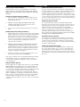
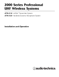
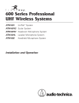
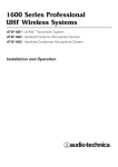
3000 Series Professional
UHF Wireless Systems
ATW-3110 UniPak™ Transmitter System
ATW-3141 Handheld Dynamic Microphone System
Installation and Operation
Professional UHF Wireless Systems
Installation and Operation
This device complies with part 15 of the FCC Rules.
Operation is subject to the condition that this device does
not cause harmful interference.
This device complies with INDUSTRY CANADA R.S.S. 210,
en conformité avec IC: RSS-210/CNR210. Operation
is subject to the following conditions: 1) This device may
not cause harmful interference and 2) this device must
accept any interference received, including interference
which may cause undesired operation.
CAUTION! Electrical shock can result from removal of the
receiver cover. Refer servicing to qualified service personnel.
No user-serviceable parts inside. Do not expose to rain or
moisture.
The circuits inside the receiver and transmitter have been
precisely adjusted for optimum performance and compliance with federal regulations. Do not attempt to open the
receiver or transmitter. To do so will void the warranty,
and may cause improper operation.
Notice to individuals with implanted cardiac pacemakers
or AICD devices:
Any source of RF (radio frequency) energy may interfere with
normal functioning of the implanted device. All wireless
microphones have low-power transmitters (less than 0.05
watts output) which are unlikely to cause difficulty, especially if they are at least a few inches away. However, since a
“body-pack” mic transmitter typically is placed against the
body, we suggest attaching it at the belt, rather than in a shirt
pocket where it may be immediately adjacent to the medical
device. Note also that any medical-device disruption will
cease when the RF transmitting source is turned off. Please
contact your physician or medical-device provider if you have
any questions, or experience any problems with the use of
this or any other RF equipment.
Introduction
Thank you for choosing an Audio-Technica professional wireless
system. You have joined thousands of other satisfied customers
who have chosen our products because of their quality, performance and reliability. This Audio-Technica wireless microphone
system is the successful result of years of design and manufacturing experience.
3000 Series systems and components operate on 200 PLLsynthesized frequencies in one or two 25 MHz-wide UHF
frequency ranges:
• Band C 541.500–566.375 MHz (TV Channels 25–30)
• Band D 655.500–680.375 MHz (TV Channels 44–49)
2
For simplicity, model numbers used throughout the manual will
reference only the basic model number without the “C” or “D”
band indications.
Each wireless system includes a receiver and either a bodypack or handheld transmitter. Individual components are also
available separately.
All 3000 Series components feature soft-touch controls for
quick, easy access to a formidable range of functions; an LCD
information display in each unit provides convenient visual
indication of unit settings and operation.
The ATW-R310 receiver features true diversity reception. Two
antennas feed two completely independent RF sections on
the same frequency; automatic logic circuitry continuously
compares and selects the superior received signal, providing
better sound quality and reducing the possibility of interference
and dropouts. Soft-touch controls provide convenient access
to a variety of functions, while an LCD information display
provides constant monitoring of system operation, including
indication of the transmitter’s battery status. The receiver is
half-width for a standard 1U 19" rack mount; rack-mount
adapters are included. Two receivers can be mounted side by
side, using an optional AT8630 joining-plate kit.
The versatile ATW-T310 UniPak™ body-pack transmitter has
both low- and high-impedance inputs plus a bias connection,
for use with dynamic and electret condenser microphones, as
well as Hi-Z instrument pickups. In addition to its programmable
functions, the transmitter features a three-position sliding cover
to limit access, if desired, to just the Power/Mute button, or to
no controls, as appropriate for the application and user.
The ATW-T341 handheld dynamic microphone/transmitter
features the same element used in the Artist Elite® AE4100
dynamic handheld microphone created for professional livesound venues.
Transmitters in the 3000 Series use two 1.5V AA batteries for
economical operation and wide availability. The receiver and
both transmitters have “fuel gauge” battery condition indicators
with low-battery warnings.
An advanced Digital Tone Lock™ tone squelch system in the
ATW-R310 receiver opens only when a 3000 Series transmitter
is detected, reducing the possibility of interference. As a
result, 3000 Series transmitters and receivers must be used
together and should not be used with components from
other Audio-Technica wireless systems, or with those of other
manufacturers.
Please note that in multiple-system applications there must be
a transmitter-receiver combination set to a separate frequency
for each input desired (only one transmitter for each receiver).
Because the wireless frequencies are within UHF TV frequency
bands, only certain operating frequencies may be useable in
a particular geographic area. System operating frequencies will
be found on page 12.
Receiver Installation
Location
For best operation the receiver should be at least 3 ft. (1 m)
above the ground and at least 3 ft. away from a wall or metal
surface to minimize reflections. The transmitter should be at
least 3 ft. from the receiver, as shown in Figure A. Keep
antennas away from noise sources such as digital equipment,
motors, automobiles and neon lights, as well as away from
large metal objects.
Output Connections
There are two audio outputs on the back panel: balanced
(32 mV) and unbalanced (50 mV). Use shielded audio cable for
the connection between the receiver and the mixer. If the
input of the mixer is a 1/4" jack, connect a cable from the 1/4"
unbalanced audio output on the back of the receiver housing
to the mixer. If the input of the mixer is an XLR-type input,
connect a cable from the balanced XLR-type audio output on
the back panel to the mixer. The two isolated audio outputs
permit simultaneous feeds to both unbalanced and balanced
inputs. For example, both a guitar amp and a mixer can be
driven by the receiver.
Antennas
Attach the included pair of UHF antennas to the antenna input
jacks. The antennas are normally positioned in the shape of a
“V” (both 45° from vertical) for best reception.
Antennas can be remotely located from the receiver. However,
due to signal loss in cables at UHF frequencies, use the
lowest-loss RF cables practical for any cable runs over 25 feet.
RG8-type is a good choice. Use only copper-shielded cable,
not CATV-type foil-shielded wire. Audio-Technica offers quality
RF cables in four lengths, as well as remote antennas; see the
Optional System Accessories section on page 11.
Power Connections
Connect the included AD1205AA in-line AC adapter to the DC
power input on the back of the receiver. Loop the small cord
from the DC plug over the cord hook above the jack, to keep
the plug from being detached by an accidental tug on the cord.
Then plug the larger cord from the in-line adapter into a
standard 120 Volt 60 Hz AC power outlet. Operation of the
receiver is controlled by the front-panel Power switch.
(Note: Units supplied to countries with 230V mains should
include an in-line AC adapter appropriate for that country.
Use the AD1205AA adapter only with 120V 60 Hz AC
power sources.)
Figure A
See pages 16-17 for illustrations.
3
Receiver Controls and Functions
Front Panel Controls and Functions (Fig. B)
1. POWER SWITCH: Press Power switch in and the receiver
readouts will light.
2. ALERT INDICATOR: The Alert Indicator lights:
(a) When the receiver is in the Function Edit mode,
(b) When no RF signal is received from transmitter,
(c) When only one or two RF signal-strength bars are on,
(d) When the transmitter is in the Mute mode,
(e) When audio modulation level from the transmitter is
close to the clipping point (AF +3/+6 bars),
(f) When only one bar of the Battery “fuel gauge” is on
(transmitter battery is weak).
3. LCD WINDOW: Liquid Crystal Display indicates control
settings and operational readings. See Figure D on page 16
for examples.
4. TUNER OPERATION INDICATOR: Indicates which Tuner
(A or B) has the better reception and is in operation. The
“B” indicator also lights to serve as confirmation of
Mode/Set button entries.
5. UP/DOWN BUTTONS: Press Up or Down arrow buttons, in
conjunction with the Mode/Set button, to step through
menus, select operating frequency and edit receiver
function choices.
6. MODE/SET BUTTON: Use in conjunction with the
Up/Down arrow buttons to step through menus, choose
operating frequency and select receiver function options.
7. MOUNTING ADAPTERS: For mounting the receiver in any
standard 19" rack. Attach adapters to the receiver with the
screws supplied and remove the four receiver feet. (Use
optional AT8630 joining-plate kit to mount two ATW-R310
receivers side-by-side.)
Rear Panel Controls and Functions (Fig. C)
8. ANTENNA INPUT JACK: BNC-type antenna connector for
Tuner “B.” Attach the antenna directly, or extend it with a
low-loss antenna cable. See the “Antennas” section on
page 3 for more details.
9. ANTENNA INPUT JACK: Input for Tuner “A.” Attach the
antenna directly, or extend it with a low-loss antenna cable.
10. AF LEVEL CONTROL: Adjusts audio output level of both AF
Output jacks; maximum output is fully clockwise.
11. GROUND LIFT SWITCH: Disconnects the ground pin of the
balanced output jack (12) from ground. Normally, the switch
should be to the left (ground connected). If hum caused by
a ground loop occurs, slide switch to the right (ground
lifted).
12. BALANCED AUDIO OUTPUT JACK: XLRM-type connector.
A standard 2-conductor shielded cable can be used to
connect the receiver output to a balanced microphone-level
input on a mixer or integrated amplifier.
13. UNBALANCED AUDIO OUTPUT JACK: 1/4" phone jack. Can
be connected to an unbalanced aux-level input of a mixer,
guitar amp or tape recorder.
14. POWER INPUT JACK: Connect the DC plug from the
included in-line AC adapter.
4
15. CORD HOOK: Loop the small DC cord around the cord
hook to keep the DC plug from pulling out accidentally.
Power On/Off
To turn the receiver on, press in the Power switch. The Alert
light and the LCD window will come on (about 1-2 seconds).
The operating frequency will be displayed in the window after
the power-up sequence. To turn the receiver off, press the
Power switch again.
LCD Window
The LCD (Liquid Crystal Display) presents a great deal of setup
and operating information clearly and conveniently. (See Figure
D for examples.)
Up/Down Arrow Buttons
In conjunction with the Mode/Set button, the arrow buttons
permit moving through the menu of functions, and choice of
settings within each function.
Mode/Set Button
The Mode/Set button shifts the receiver from normal operation
into Menu mode and, in conjunction with the Up/Down arrow
buttons, permits selection of different features and changing of
their stored values in the Edit mode.
How to Make Setting Changes
1. From the normal operating mode, press the Mode/Set
button once to enter the Function Menu mode. (Only the
frequency will remain in the LCD window, and the
receiver’s audio output will be cut off.)
2. Use the Up/Down arrow buttons to reach the desired
function. The value in the LCD window is the current
setting for that function.
3. Press the Mode/Set button once again to open the list of
available choices for that function. The value will flash,
indicating that it can be changed (Edit mode).
4. Use the arrow buttons to go through the available choices,
stopping on the desired new choice.
5. (a) To accept and enter the new choice, press and hold the
Mode/Set button until “STORED” appears in the LCD. This
changes the value and puts the function of the buttons
back at Menu level (step 2 above). (The “B” tuner light
will come on while the Mode/Set button is depressed, to
confirm its action.)
(b) To “back out” of the Edit mode without making a new
choice, simply press the Mode/Set button once. The word
“ESCAPE” will appear in the window and the function of
the buttons will revert to the Menu level (step 2 above),
without making any changes.
6. Repeat this selection process for any other function
changes desired. When finished with any changes, use
the arrow buttons to move to “QUIT”. Press the Mode/Set
button once to exit the menu and return the receiver to
normal operation. (“RF” and “AF” will reappear in the
window, indicating the return to normal receiver operation,
with the receiver’s audio output again enabled.)
How to Restore Default Settings
To return all the receiver functions to their original factorydefault settings, first turn the receiver off. Then hold in the
Mode/Set button while pressing the Power switch. The LCD
will briefly show “RESET”, followed by “WAIT” (release the
Mode/Set button), before commencing normal-mode operation
at the default settings.
Receiver Controls and Functions
When the receiver is in the Menu or Edit mode, its audio
output is silenced. Once control-setting operations are
completed (or Escape is used), normal receiver operation
will resume with its audio output restored.
While in the Edit mode, if no action is taken for approximately 30 seconds (no buttons pressed), the receiver will
“back out” to the Menu mode. Similarly, after about 30
seconds of inaction in the Menu mode, the receiver will
“back out” to normal receiver operation with audio output
restored.
High-pass Filter
Internal high-pass filter circuitry may be set to four positions:
High-pass Off, or a 6 dB, 12 dB or 18 dB slope at 150 Hz. The
default setting is Off (“HP OFF”). Increasing the slope of the
high-pass filter further suppresses unwanted low frequencies,
while maintaining the frequency response in the desired audio
range.
Meter Hold Setting
When activated (“MH ON”), this function permits the
bar-meters in the LCD window to capture and display the
highest-level “AF” audio modulation (a solid bar) and the
lowest-level "RF" signal (a flashing bar) received from the
transmitter. This is particularly useful when setting up the
system initially, during a sound-check, or when diagnosing
operating problems. The default setting is Off (“MH OFF”).
(Continued)
When the Meter Hold is On, it is possible to reset it – to obtain
a new set of RF and AF readings – without turning it off-and-on
using the Menu/Edit functions. Simply press the transmitter’s
Power/Mute button once (to mute the transmitter) and wait
until the receiver’s Alert light comes on, indicating the Mute
condition. Then press the transmitter’s Power/Mute button once
again, to un-mute the transmitter. After the Alert light goes
out, a new set of min/max RF/AF readings will be indicated on
the bar-meters. (Note that, depending upon the digital updatingand-confirming sequence of the Mute condition data from the
transmitter, it may take several seconds for the Alert light
condition to change. The Meter Hold function is not reset
until the Alert light has turned on, then turned off.)
Digital Tone Lock™ Squelch
The 3000 Series employs a unique Digital Tone Lock squelch
system that provides enhanced rejection of interference. In
addition to providing highly effective control of unwanted noise,
the Tone Lock signal from the transmitter also conveys data on
the transmitter’s battery condition and mute status back to the
receiver for display.
The squelch level is adjustable from 15 dB (the default value) to
42 dB in 3 dB steps. Increasing the squelch level – also called
“tightening the squelch” – can cause a reduction in useable
range of the wireless transmitter, so use the lowest value that
reliably mutes the unwanted RF signals. (If interference is a
problem, first consider trying a different frequency.)
Receiver Functions
Function Menu
Default Setting*
Choices (Edit) ▲▼
Wrap-around**
(Receiver powers-up at Frequency)
▲▼ Frequency
Lowest in band†
200 discrete frequencies
Yes
▲▼ Quit (exit Menu)
QUIT
Press Mode/Set to exit
▲▼ Squelch
SQ 15 dB
SQ 15 dB to SQ 42 dB in 3 dB steps
No
▲▼ Meter Hold
MH OFF
MH OFF
Yes
▲▼ High-pass Filter
HP OFF
HP OFF
--
MH ON
HP –6
HP –12
HP –18
No
* To reset to Default values, hold in the Mode/Set button while pressing the Power button to turn on the unit.
** Continue in the same Up/Down direction and choices “wrap around” to the other end of the range.
† Band C: 541.500 MHz; Band D: 655.500 MHz.
Table 1. Receiver Functions
See pages 16-17 for illustrations.
5
Transmitter Controls And Functions
Refer to Figures E, F, G and H for an overview of transmitter
features and controls.
PWR.LOC
LCD Window
The Liquid Crystal Display presents a great deal of setup and
operating information clearly and conveniently (See examples
in Fig. J). The LCD in the transmitters is designed for greatest
contrast and best viewing with the window rotated somewhat
away from the viewer (about 30 degrees), not straight-on, for
a more convenient holding/viewing position.
Power/Mute Button
The transmitters have a combination Power and Mute switch.
When used in combination with the programmed choices
explained below, the various functions available to the
transmitter user may be tailored to fit personal preferences
or particular situations of use.
Power On/Off
To turn the transmitter on, press and hold the Power/Mute
button until the red power indicator and the LCD window come
on (about 1-2 seconds). The operating frequency will show in
the window after the power-up sequence.
To turn the transmitter off, press and hold the Power/Mute
button again, until the red power indicator and the LCD window
are extinguished (about 1-2 seconds). The LCD window will
show “PWR.OFF” before shutdown.
Mute Off/On
When the transmitter is muted, it produces RF with no audio
signal modulation. When the transmitter is un-muted, it
produces both RF and audio.
To mute the transmitter (cut off the audio, but continue the RF
output), press and release the Power/Mute button once. A
small “MUTE” will appear in the LCD window, just below the
frequency (Fig. J-2).
To un-mute the transmitter (restore the audio), press and
release the Power/Mute button once again. The “MUTE” will
disappear from the LCD window.
Power/Mute Locks
Programmable Power/Mute Locks limit the functioning of the
Power/Mute button as desired for particular users and/or applications. Power can be locked On; Mute can be locked Off.
Selection of the desired locks, if any, is made through the
function menu:
Setting
Description
NO.LOC
The normal Power and Mute functions are fully
operational.
ALL.LOC
MUT.LOC
6
Both the Power and Mute functions are locked
into their status as of the time “ALL.LOC” is
applied. (Power On, and Mute either On or Off.)
Note: ALL.LOC must be re-accessed and the
setting changed to turn the transmitter off.
In this mode, the audio cannot be muted. The
Power functioning is unaffected. (If MUT.LOC is
applied while the transmitter is muted, pressing
the Power/Mute button once will return to
un-muted operation; thereafter the Mute function
is disabled until the setting is changed again.)
Power is locked On as of the time “PWR.LOC”
is applied. The Mute functioning is unaffected.
Note: When in the PWR.LOC mode, the
transmitter may be turned off by: (1) Re-accessing
the .LOC Menu and changing the setting, or
(2) Removing and re-installing the batteries.
When the transmitter is turned on again, it will
power-up in the NO.LOC mode. (Only the
PWR. LOC function will change when batteries
are removed; all other settings remain stored in
memory.)
If an attempt is made to take an action that currently is locked
out, the LCD will display “LOC.KED” briefly, then return to its
previously-displayed contents.
Audio Input Selector
The UniPak™ body-pack transmitter provides input connections
for both low-impedance (Lo-Z) microphones and highimpedance (Hi-Z) instruments. A wide range of Audio-Technica
Wireless Essentials™ microphones and cables is available
pre-terminated with the appropriate professional latching
connector. (See page 11.)
Selection of the desired input – microphone or instrument – is
made through the function menu. Depending upon the input
selected, a small “MIC” or “INST” will show in the LCD
window, just below the frequency. (In the handheld transmitter,
only “MIC” will show in the LCD window.)
Setting Audio Input Level
A 4-position audio input gain setting, selected through the
function menu, serves to match the audio input level to the
transmitter for best modulation with minimum distortion.
Available choices are +12 dB, +6 dB, 0 dB and –6 dB. The
default value is +6 dB. Select the highest setting that does
not result in over-modulation with the highest audio/instrument
input levels (an AF indication on the receiver no higher than
“0”); watch the receiver’s “AF” meter “+3/+6” indications and
the Alert light to make certain they are not triggered by the
highest audio levels.
The transmitter’s normally-on red LED power indicator will blink
off if the peak audio input exceeds the maximum desirable
level.
Restore Default Settings
A “PRESET” selection in the menu permits resetting of all
transmitter functions to their factory-default values.
1.
Press the Set button once to move to Menu mode.
2.
Press the Up arrow twice to move to “PRESET” in the
LCD window.
3.
Press the Set button once and “LOAD” will appear in the
LCD.
4.
Press and hold the Set button until “DEF” appears in the
LCD.
5.
Press and hold the Set button until “LOADED” appears
briefly in the LCD. The window will then revert to
“PRESET”.
6.
Press the Down arrow once to move to “QUIT”.
7.
Press the Set button once to exit the Menu mode and
return to normal operation, with all factory-default settings
restored.
Transmitter Controls And Functions
UniPak Transmitter Functions
Function Menu
Default Setting
(Continued)
Choices (Edit) ▲▼
Wrap-around**
(Transmitter powers-up at Frequency)
▲▼ Frequency
Lowest in band†
200 discrete frequencies
Yes
▲▼ RF Power
RF LOW
RF LOW
Yes
▲▼ Audio Input Level
+6 dB
–6 dB
▲▼ Power/Mute Locks
NO.LOC
NO.LOC
ALL.LOC
▲▼ Input Select
MIC
MIC
INSTR
▲▼ Reset to Defaults
PRESET
LOAD
(b) hold until: DEF (c) hold until: LOADED
▲▼ Quit (exit Menu)
QUIT
Press Set to exit
RF HI
0 dB
+6 dB
+12 dB
MUT.LOC
No
PWR.LOC
Yes
Yes
---
** Continue in the same Up/Down direction and choices “wrap around” to the other end of the range.
† Band C: 541.500 MHz; Band D: 655.500 MHz.
Table 2. UniPak Transmitter Functions
Handheld Transmitter Functions
Function Menu
Default Setting
Choices (Edit) ▲▼
Wrap-around**
(Transmitter powers-up at Frequency)
▲▼ Frequency
Lowest in band†
200 discrete frequencies
Yes
▲▼ RF Power
RF LOW
RF LOW
Yes
▲▼ Audio Input Level
+6 dB
–6 dB
▲▼ Power/Mute Locks
NO.LOC
NO.LOC
ALL.LOC
▲▼ Reset to Defaults
PRESET
LOAD
(b) hold until: DEF (c) hold until: LOADED
▲▼ Quit (exit Menu)
QUIT
Press Set to exit
RF HI
0 dB
+6 dB
+12 dB
MUT.LOC
No
PWR.LOC
Yes
---
** Continue in the same Up/Down direction and choices “wrap around” to the other end of the range.
† Band C: 541.500 MHz; Band D: 655.500 MHz.
Table 3. Handheld Transmitter Functions
See pages 16-17 for illustrations.
7
Transmitter Setup
Battery Selection and Installation
Each transmitter uses two 1.5V AA batteries, not included.
Alkaline type is recommended. Always replace both batteries.
Make certain the transmitter power is Off before replacing
batteries.
UniPak™ Transmitter Battery Installation
1. Open the battery compartment door by sliding the catch
down (Fig. K). (If no batteries are inside, the door will not
spring open by itself.)
2.
Observe correct polarity as marked on the metal
contacts on the door and carefully insert two fresh
1.5V AA alkaline batteries (Fig. L).
3.
Close the door, making certain the latch clicks securely in
place.
Handheld Transmitter Battery Installation
1. While holding the lower body cover (near the LCD window),
grasp the upper part of the transmitter body just below the
grille and unscrew it at least four complete turns (Fig. G);
then slide the lower body cover down until it stops (Fig. H).
Once the cover has been lowered, turn the transmitter
over to reveal the battery compartment on the side
opposite the LCD window.
2.
3.
Observe correct polarity as marked inside the battery
compartment and carefully insert two fresh 1.5V AA
alkaline batteries (Fig. M). Insert the first battery and slide
it down. Then insert the second battery, bottom first, into
the space remaining. Make certain the batteries are fully
seated in the battery compartment.
Slide the lower body cover back up the body, then screw
the housing together. Do not overtighten.
Note: Remove batteries from the handheld transmitter starting
at the bottom (– end) of the top battery (Fig. M). The top
(+ end) of the top battery is captured in a recess and will not
come straight out.
Battery Condition Indicator
After the batteries are installed, turn the power on by pressing
and holding the Power/Mute button. The small red power-on
LED (Fig. E/F) should light and the LCD window should come
on. If this does not happen, the batteries are installed incorrectly
or they are dead. The transmitter’s “fuel gauge” battery
indicator displays a maximum of four bar segments. When it
flashes “LOW.BAT”, the batteries should be replaced immediately to ensure continued operation. (The receiver also displays
transmitter battery condition in the LCD window with bar
segments; the Alert indicator comes on to warn of a low-battery
condition.)
8
UniPak Transmitter Input Connection
Connect an audio input device (microphone or guitar cable) to
the audio input jack on the bottom of the transmitter. A number
of Audio-Technica professional microphones and cables are
available separately, pre-terminated with a UniPak input connector (see “Optional System Accessories” on page 11). The cable
connector latches automatically when inserted into the transmitter jack. To unlatch and remove the connector, simply pull up on
the connector’s knurled metal collar.
UniPak Transmitter Antenna
The UniPak transmitter includes a field-replaceable flexible
antenna. For best results, allow the antenna to hang freely and
full length from the bottom of the transmitter. If the received
signal is marginal, experiment with different transmitter
positions on your body or instrument; or try repositioning the
receiver or using remote receiver antennas. Since the
transmitter antenna simply screws in, check it occasionally to
make certain it is snugly attached (finger-tight). Do not change
the length of the transmitting antenna.
Handheld Transmitter Antenna
The antenna for the handheld mic/transmitter is in the black,
non-metallic section at the bottom of the unit (Fig. F). For best
results, hold the mic/transmitter naturally, around its painted
metal case; holding or otherwise covering the antenna housing
may affect operating range.
UniPak Transmitter Mounting Clip
The UniPak transmitter’s mounting clip may be installed with
the case positioned either “up” or “down,” depending upon
which is preferred for the application. To turn the clip around,
spring the ends of the clip out of the two holes on the sides of
the transmitter case (Fig. E) and reinstall it facing in the opposite
direction.
System Operation
frequency. Press either arrow for single steps, or hold down
either arrow for rapid cycling through the range.
Frequencies “wrap around” when the top or bottom of the
band is reached. Select the exact frequency displayed on
the receiver.
Switch on the receiver. Do not switch on the transmitter yet.
Selecting/Setting Frequency
Selection of the desired operating frequency is made through
the function menus. It’s usually best to start by setting the
receiver’s frequency, to determine there is no local interference
on that frequency. Then, always make certain to set the transmitter to the receiver’s exact frequency. The receiver’s unique
Digital Tone Lock system squelches the audio only, permitting
any RF energy on the frequency to show on the “RF”
bar-meter.
3.
To activate this frequency selection, press and hold the
Set button until the word “STORED” appears in the
transmitter’s window. (If you do not wish to complete this
selection, just press the Set button once: the word
“ESCAPE” will appear briefly in the window and the
transmitter will return to the Menu mode.)
Note: It’s often convenient to start with the factory-default
frequency, if there is no TV station on Channel 25 (for Band C
systems) or Channel 44 (for Band D systems).
4.
When finished entering a frequency, press the Up arrow
button once to move to “QUIT”. Then press the Set button
once to exit the menu. The word “MENU” in the transmitter window will go off, indicating the return to normal
operation.
Receiver On…
The Alert indicator and the LCD window will light up; the
normal-operation LCD display will appear after 1-2 seconds (Fig.
D-1). If any of the bars show in the “RF” bar-graph meter, there
may be RF interference in the area. If this occurs, select another
frequency as explained below. (If the Meter Hold function has
been selected, one of the RF bars will be flashing, indicating
the lowest RF level received.)
When the transmitter is switched on and in normal operation,
the receiver’s “RF” signal-level bars will display from bottom to
top, with more bars indicating increased signal reception. For
optimum performance at least four, and preferably five or more,
of the RF indicators should be displayed.
Setting Receiver Frequency
1. Press the Mode/Set button once; then only the frequency
will appear in the LCD window. (The receiver is now in the
Menu mode.) See Figure D-2.
Setting Levels
Correct adjustment of transmitter audio input, receiver audio
output, and mixer/amplifier input and output levels is important
for optimum system performance.
2.
Press the Mode/Set button again; the Alert light will come
on and the frequency in the window will flash. (The receiver
is now in the Edit mode, Fig. D-3.)
Set Transmitter Audio Input Level
A 4-position audio input gain setting, selected through the
function menu, serves to match the audio input level to the
transmitter for best modulation with minimum distortion.
3.
Use the Up/Down arrow buttons to change the frequency.
Press either arrow for single steps, or hold down either
arrow for rapid cycling through the band. Frequencies
“wrap around” to the other end of the range when the top
or bottom of the band is reached. Choose a frequency
appropriate for your area, avoiding frequencies with active
TV channels. (See the frequency listings on page 12.)
4.
To activate this frequency selection, press and hold the
Mode/Set button until the word “STORED” appears in the
receiver’s window. (If you do not wish to complete this
particular selection, just press the Mode/Set button once.
The word “ESCAPE” will appear briefly in the window and
the receiver will return to the Menu mode.)
5.
When finished entering a frequency, press the Down arrow
button once to move to “QUIT”. Then press the Mode/Set
button once to exit the menu. The “RF” and “AF” scales
will reappear in the window, indicating the return to normal
operation.
Transmitter On…
Turn on the transmitter by pressing and holding the Power/Mute
button (Fig. E/F) for a second or two, until the red power
indicator and the LCD window have come on.
Setting Transmitter Frequency
1. Press the Set button once and the small word “MENU” will
appear above the frequency. Press the Set button again
and the small flashing word “EDIT” will appear to the right
of “MENU”. See Figures J-3 and J-4.
2.
Use the Up/Down arrow buttons to change the transmitter
See pages 16-17 for illustrations.
Available choices are +12 dB, +6 dB, 0 dB and – 6 dB. The
default setting is +6 dB. Select the highest setting that does
not result in over-modulation with the highest audio/instrument
input levels (an AF indication on the receiver no higher than
“0”); watch the receiver’s “AF” bar-graph “+3/+6” indications
and the Alert light, to make certain that they are not triggered
by the highest audio levels.
The transmitter’s normally-on red LED power indicator will blink
off if the peak audio input exceeds the maximum desirable
level.
RF Power Adjustment
RF power may be set to “RF HI” (30 mW nominal) or “RF
LOW” (10 mW nominal) through the function menu. The default
setting is “RF LOW”. While the High setting normally provides
maximum operating range, the Low setting will help extend
battery life. The Low setting may also be preferred in multichannel systems, or when operating very close to the receiver,
to reduce the possibility of interference or overload.
RF Interference
Please note that wireless frequencies are shared with other
radio services. According to Federal Communications
Commission regulations, “Wireless microphone operations are
unprotected from interference from other licensed operations in
the band. If any interference is received by any Government or
non-Government operation, the wireless microphone must
cease operation...”
If you need assistance with operation or frequency selection,
please contact your dealer or the Audio-Technica professional
division. Extensive wireless information also is available on the
Audio-Technica Web site at www.audio-technica.com.
9
Specifications†
OVERALL SYSTEM
UHF Operating Frequency
Band C:
Band D:
Number of Channels
Frequency Stability
Modulation Mode
Normal Deviation
Operating Range
Operating Temperature Range
Frequency Response
ATW-R310 RECEIVER
Receiving System
Image Rejection
Signal-to-noise Ratio
Total Harmonic Distortion
Sensitivity
Intermediate Frequency
Audio Output
Unbalanced:
Balanced:
Output Connectors
Unbalanced:
Balanced:
Power Supply
Dimensions
Weight
Accessories Included
10
541.500 to 566.375 MHz
655.500 to 680.375 MHz
200 total per band
±0.005%, Phase Lock Loop frequency
control
FM
±10 kHz
300' typical
41° F (5° C) to 113° F (45° C)
70 Hz to 15 kHz
Dual independent receivers, automaticswitching diversity
60 dB nominal, 55 dB minimum
110 dB at 35 kHz deviation
(IEC-weighted), maximum modulation
75 kHz
≤1% (10 kHz deviation at 1 kHz)
24 dBµV (S/N 60 dB at 5 kHz deviation,
IEC-weighted)
85.38 MHz, 10.7 MHz
50 mV (at 1 kHz, ±5 kHz deviation,
10k ohm load)
32 mV (at 1 kHz, ±5 kHz deviation,
10k ohm load)
/4" TS (“mono”) phone jack
XLRM-type
1
120V AC 60 Hz, or 12-18V DC, 500 mA,
center positive, with external supply
8.27" (210.0 mm) W x 1.93" (49.0 mm) H
x 6.93" (176.0 mm) D
2.4 lbs (1.1 kg)
AD1205AA 120V 60 Hz in-line AC adapter;
two flexible UHF antennas; rack-mount
adapters
ATW-T310 UNIPAK™ TRANSMITTER
RF Power Output
High: 30 mW; Low: 10 mW, nominal
Spurious Emissions
Under federal regulations
Dynamic Range
≥110 dB, A-weighted
Input Connections
High impedance, low impedance, bias
Antenna Tip Color
Band C:
Blue
Band D:
Green
Batteries (not included)
Two 1.5V AA alkaline
Current Consumption
High: 200 mA; Low: 150 mA, typical
Battery Life
Approximately 6 hours (High); 8 hours
(Low), depending on battery type and
use pattern
Dimensions
2.60" (66.0 mm) W x 3.43" (87.0 mm) H
x 0.94" (24.0 mm) D
Net Weight (without batteries)
2.8 oz (80 grams)
ATW-T341 HANDHELD TRANSMITTER
RF Power Output
High: 30 mW; Low: 10 mW, nominal
Spurious Emissions
Under federal regulations
Dynamic Range
≥110 dB, A-weighted
Microphone Element
Dynamic cardioid (unidirectional)
Batteries (not included)
Two 1.5V AA alkaline
Current Consumption
High: 230 mA; Low: 180 mA, typical
Battery Life
Approximately 6 hours (High); 8 hours
(Low), depending on battery type and
use pattern
Dimensions
9.33" (237.0 mm) long, 1.89" (48.0 mm)
diameter
Net Weight (without batteries)
9.9 oz (280 grams)
Accessory Included
AT8456a Quiet-Flex™ stand clamp
†
In the interest of standards development, A.T.U.S. offers full details on its test methods to
other industry professionals on request.
Specifications are subject to change without notice.
Optional System Accessories
WIRELESS ESSENTIALS™ MICROPHONES AND CABLES
All Wireless Essentials accessories are terminated for use with ATW-T310
and other UniPak™ transmitters.
AT829cW
Miniature cardioid condenser lavalier microphone.
Includes clothing clip and windscreen.
MT830cW
Miniature omnidirectional condenser lavalier
microphone. Includes clothing clip and windscreen.
MT830cW-TH “Theater” model, same as MT830cW except beige color
mic and cable for concealment.
AT831cW
Miniature cardioid condenser lavalier microphone.
Includes clothing clip and windscreen.
AT851cW
Surface-mount wide-range hemi-cardioid condenser
microphone.
AT857AMLcW 19" gooseneck cardioid microphone.
Mounts to 5/8"-27 thread. Includes windscreen.
AT889cW
Headworn noise-canceling condenser microphone.
Includes windscreen and cable clip.
AT898cW
Subminiature cardioid condenser lavalier microphone.
Includes clothing clip base, viper clip base, magnet clip base,
three single mic holders, two double mic holders and
two windscreens.
AT899cW
Subminiature omnidirectional condenser lavalier microphone.
Includes AT899AK accessory kit.
AT899cW-TH “Theater” model, same as AT899cW except beige color mic
and cable concealment. Includes AT899AK-TH accessory kit.
ATM35cW
Cardioid condenser instrument microphone.
Includes AT8418 clip-on instrument mount.
ATM73cW
Headworn cardioid condenser microphone.
Includes windscreen.
ATM75cW
Headworn cardioid condenser microphone.
Includes windscreen.
PRO 8HEcW
Headworn hypercardioid dynamic microphone.
Includes windscreen and cable clip.
PRO 35xcW
Cardioid condenser instrument microphone.
Includes AT8418 clip-on instrument mount.
AT-GCW
Hi-Z instrument/guitar cable with 1/4" phone plug.
XLRW
Connecting cable for UniPak transmitter with an XLRF-type
input connector, for Lo-Z microphones with XLRM-type
output terminations.
RECEIVER ACCESSORIES
AEW-DA550C UHF (540–565 MHz) active unity-gain antenna distribution
system provides two “1-in, 4-out” RF channels; connects a
pair of antennas to as many as four diversity receivers;
cascade output provided as a directional coupler. AC passthrough allows daisy-chain AC hookup. Defeatable antenna
power. Metal receiver chassis with reinforced mounting ears
and rear rack mount capability. Includes detachable IEC
power cable, IEC pass-through cable, ten RF cables, frontmount antenna cables and connectors, four DC power
cables to power up to four 3000 Series receivers. Mounts in
a single 19" rack space. For use with ATW-R310C (Band C)
receivers.
AEW-DA660D Same as AEW-DA550C except for 655-680 MHz operation.
For use with ATW-R310D (Band D) receivers.
AT8630
Joining-plate kit allows rack-mounting two ATW-R310
receivers side-by-side in a single (1U) 19" rack space.
ATW-A20
Pair of UHF ground-plane antennas with 5/8"-27 thread for
mounting to microphone stands, etc. For use with
ATW-R310D (Band D) receivers. Takes RF cables with BNC
connectors, not included; see RF Cables below.
ATW-A49
Pair of UHF wide-band directional LPDA (log periodic dipole
array) antennas provide enhanced signal pickup for UHF
wireless systems throughout a wide band range
(440-900 MHz). Each antenna paddle is matched to 50 ohms
impedance with intergral high-quality low-loss BNC
connector; 6 dB gain. For permanent or temporary
installation; mounts to 5/8"-27 threads.
ATW-RA1
Rack-mount antenna kit brings antenna inputs to the front of
receiver for ease of setup, or when receiver is enclosed in a
metal rack. Includes a pair of extendible antennas. NOTE:
Two adapter kits are required when mounting two receivers
side-by-side in a single 19" rack space.
RF Cables
Low-loss design, 50 ohm impedance, with BNC-to-BNC
connectors:
AC12
RG58-type cable (12')
AC25
RG8-type cable (25')
AC50
RG8-type cable (50')
AC100 RG8-type cable (100')
TRANSMITTER ACCESSORIES
AT8114
Foam windscreen for handheld transmitter.
AT8141
Water-resistant pouch for UniPak transmitter.
AT8390
Shielded audio cable with 1/4" to 1/4" phone plugs.
Available in a variety of lengths.
(Also available with one straight and one 90° phone plug
as the AT8316.)
AT8456a
See pages 16-17 for illustrations.
Quiet-Flex™ stand clamp for handheld transmitter,
5
/8"-27 threads.
11
3000 Series UHF Wireless Operating Frequencies
TV Ch.
Band C: 541.500 - 566.375 MHz
541.500
541.625
541.750
541.875
26
542.000
542.125
542.250
542.375
542.500
542.625
542.750
542.875
26
543.000
543.125
543.250
543.375
543.500
543.625
543.750
543.875
26
544.000
544.125
544.250
544.375
544.500
544.625
544.750
544.875
26
545.000
545.125
545.250
545.375
545.500
545.625
545.750
545.875
26
546.000
546.125
546.250
546.375
546.500
546.625
546.750
546.875
26
547.000
547.125
547.250
547.375
547.500
547.625
547.750
547.875
27
548.000
548.125
548.250
548.375
548.500
548.625
548.750
548.875
27
549.000
549.125
549.250
549.375
549.500
549.625
549.750
549.875
27
550.000
550.125
550.250
550.375
550.500
550.625
550.750
550.875
27
551.000
551.125
551.250
551.375
551.500
551.625
551.750
551.875
27
552.000
552.125
552.250
552.375
552.500
552.625
552.750
552.875
27
553.000
553.125
553.250
553.375
553.500
553.625
553.750
553.875
28
554.000
554.125
554.250
554.375
554.500
554.625
554.750
554.875
28
555.000
555.125
555.250
555.375
555.500
555.625
555.750
555.875
28
556.000
556.125
556.250
556.375
556.500
556.625
556.750
556.875
28
557.000
557.125
557.250
557.375
557.500
557.625
557.750
557.875
28
558.000
558.125
558.250
558.375
558.500
558.625
558.750
558.875
28
559.000
559.125
559.250
559.375
559.500
559.625
559.750
559.875
29
560.000
560.125
560.250
560.375
560.500
560.625
560.750
560.875
29
561.000
561.125
561.250
561.375
561.500
561.625
561.750
561.875
29
562.000
562.125
562.250
562.375
562.500
562.625
562.750
562.875
29
563.000
563.125
563.250
563.375
563.500
563.625
563.750
563.875
29
564.000
564.125
564.250
564.375
564.500
564.625
564.750
564.875
29
565.000
565.125
565.250
565.375
565.500
565.625
565.750
565.875
30
566.000
566.125
566.250
566.375
25
---
---
---
TV Ch.
44
12
---
---
---
---
---
Band D: 655.500 - 680.375 MHz
---
---
---
655.500
655.625
655.750
655.875
45
656.000
656.125
656.250
656.375
---
656.500
656.625
656.750
656.875
45
657.000
657.125
657.250
657.375
657.500
657.625
657.750
657.875
45
658.000
658.125
658.250
658.375
658.500
658.625
658.750
658.875
45
659.000
659.125
659.250
659.375
659.500
659.625
659.750
659.875
45
660.000
660.125
660.250
660.375
660.500
660.625
660.750
660.875
45
661.000
661.125
661.250
661.375
661.500
661.625
661.750
661.875
46
662.000
662.125
662.250
662.375
662.500
662.625
662.750
662.875
46
663.000
663.125
663.250
663.375
663.500
663.625
663.750
663.875
46
664.000
664.125
664.250
664.375
664.500
664.625
664.750
664.875
46
665.000
665.125
665.250
665.375
665.500
665.625
665.750
665.875
46
666.000
666.125
666.250
666.375
666.500
666.625
666.750
666.875
46
667.000
667.125
667.250
667.375
667.500
667.625
667.750
667.875
47
668.000
668.125
668.250
668.375
668.500
668.625
668.750
668.875
47
669.000
669.125
669.250
669.375
669.500
669.625
669.750
669.875
47
670.000
670.125
670.250
670.375
670.500
670.625
670.750
670.875
47
671.000
671.125
671.250
671.375
671.500
671.625
671.750
671.875
47
672.000
672.125
672.250
672.375
672.500
672.625
672.750
672.875
47
673.000
673.125
673.250
673.375
673.500
673.625
673.750
673.875
48
674.000
674.125
674.250
674.375
674.500
674.625
674.750
674.875
48
675.000
675.125
675.250
675.375
675.500
675.625
675.750
675.875
48
676.000
676.125
676.250
676.375
676.500
676.625
676.750
676.875
48
677.000
677.125
677.250
677.375
677.500
677.625
677.750
677.875
48
678.000
678.125
678.250
678.375
678.500
678.625
678.750
678.875
48
679.000
679.125
679.250
679.375
679.500
679.625
679.750
679.875
49
680.000
680.125
680.250
680.375
---
---
---
---
Ten Tips to Obtain the Best Results
1. Use only fresh alkaline batteries. Do not use “general
purpose” (carbon-zinc) batteries.
6. The receiver and transmitter must be set to the same
frequency.
2. Position the receiver so that it has the fewest possible
obstructions between it and the normal location of the
transmitter. Line-of-sight is best.
7. A receiver cannot receive signals from two transmitters
at the same time.
3. The transmitter and the receiver should be as close
together as conveniently possible, but no closer than
three feet (1 m).
4. Avoid placing the receiver in a low or shielded location
where the transmitter and receiver antennas are not
visible to each other. If necessary, use remotely-located
receiver antennas.
5. Avoid placing the receiver near computers or other RF
generating equipment.
8. Do not obstruct the handheld transmitter’s antenna
(located at the base) or attached body-pack transmitter’s
antenna with your hands.
9. You need to change frequencies 1) when a strong
interference signal is received, 2) when audio quality is
poor due to weak RF, or 3) during multiple-system
operation in order to select an interference-free
frequency.
10. Turn the transmitter off when not in use. Remove the
batteries if the transmitter is not to be used for a period
of time.
A word about "Digital TV"
The advent of "digital TV" has greatly increased the number of TV broadcast transmitters in operation and has added a new and
different type of TV signal to the airwaves.
Digital TV spreads its transmitted power fairly uniformly across an entire 6 MHz-wide TV channel, effectively “blocking” use of
any of the frequencies for wireless mic systems in the local area.
By comparison, the original type of television transmission, “analog TV,” concentrates the broadcast power within certain fairly
narrow frequency ranges within the 6 MHz-wide TV channel. As a result, wireless systems usually can still operate on
frequencies where the power is not concentrated, even through an analog TV station is transmitting. This ability for wireless
systems to “co-exist” with analog TV stations permits the use of many more frequencies than would seem to be available, just
based upon the number of “TV channels in use” locally.
And while “analog vs. digital” does add a new complexity to wireless frequency selection and system design, it remains the case
that your wireless needs can be achieved. Our website, www.audio-technica.com, offers a wide range of information about
multi-channel operation and frequency selection. In addition, A-T’s resources are on call at any time to assist you in specifying,
installing and troubleshooting large wireless systems.
For future reference, please record your system information here:
Receiver
ATW-R310___
C/D
Transmitter
ATW-T310___
C/D
ATW-T341___
C/D
S/N_____ _____ _____ _____ _____ _____ _____
Serial Number appears on the FCC label on the back of the receiver.
S/N_____ _____ _____ _____ _____ _____ _____
Serial Number appears on the FCC label on the back of the transmitter.
S/N_____ _____ _____ _____ _____ _____ _____
Serial Number appears in a recess in the battery compartment of the transmitter.
13
Troubleshooting Guide
Receiver is not on (LCD window does not light).
• Receiver Power switch is not pressed in.
• Small DC power cord from included in-line power supply
is not plugged into jack on back of receiver. (Use the cord
hook to secure it.)
• The in-line power supply is not plugged into AC power
outlet.
• AC power is not present at the AC outlet.
Receiver is on (LCD window lights)
• No sound • Alert light is OFF:
✓“RF”, “AF” and “BATT” legends do not appear in LCD…
• Receiver is in the Menu mode. [See p. 4.]
✓“RF” and "AF" level meters both show good signals.
• AF Level control on back of receiver not turned up
(clockwise). [See p. 4.]
Note: If the “AF” level meter shows a good signal on the
receiver when the transmitter is receiving audio input,
and the AF Level control is turned up, then the problem
is in connections to or control settings on the mixer,
amplifier, etc.
✓Only “RF” level meter shows good signal; no “AF”
signal.
• No sound input to mic.
• ATW-T310 body-pack only: Wrong input selected (“INST”
or “MIC”). [See p. 6.]
Receiver is on (LCD window lights)
• No sound • Alert light is ON:
✓“RF”, “AF” and “BATT” legends do not appear in LCD,
and LCD is flashing…
• Receiver is in the Edit mode. [See p. 4.]
✓“RF” and “AF” level meters both show good signals.
• The transmitter audio level is too high
(“+3”/”+6” on receiver). [See p. 9.]
• Batteries may be weak. (Check “BATT” fuel gauge.)
✓Only “RF” level meter shows good signal; no “AF”
signal.
• Transmitter may be muted. (Note: Normally it takes
several seconds for the Alert light to turn off/on after
the transmitter mute is switched off/on.) [See p. 5.]
✓Neither the “RF” nor the “AF” level meter shows any
signal.
• Receiver antennas not connected.
• Transmitter is turned off.
• Transmitter batteries are dead or missing.
• Transmitter is set to a different frequency.
• Transmitter and receiver not in same Band (C/D).
14
Receiver is on (LCD window lights)
• Distorted sound • Alert light is ON:
✓“RF” and/or “AF” level meters may show good signals.
• The transmitter audio level is too high (“+3”/”+6” on
receiver). [See p. 9.]
• Received RF level may be too low (only one or two bars).
• Batteries may be weak; check “BATT” fuel gauge.
(Sound may or may not be distorted.)
Momentary loss of sound/noisy sound as transmitter is
moved around performing area.
• Transmitter and receiver antennas not in line-of-sight
(or perhaps too far apart). Adjust positions of units so
they are visible to each other/closer together; use
remote antennas located closer to the transmitter
location.
• Signal blockage or interference from large metal objects,
other wireless units located too close and/or on
incompatible frequencies, computer or lighting
equipment.
• Squelch setting may be set “tighter” than it needs to
be. (Recommended squelch setting is the
minimum/default value, 15 dB.) [See p. 5.]
Tip: Use the Meter Hold function to help identify and
resolve (or at least avoid) RF problem locations.
[See p. 5.]
With transmitter on, received signal is noisy or contains
extraneous sounds.
• Batteries may be weak. Check “BATT” fuel gauge and
“RF” meter level.
• Local TV transmissions on this frequency.
• Nearby sources of RF interference, such as computers,
lighting equipment, etc.
• Two transmitters may be operating on the same
frequency. Locate and turn one off or change its
frequency.
• In multiple-system use, two (or more) incompatible
frequencies may have been selected.
Troubleshooting’s First Line of Defense: Factory-Default Settings
Incorrect settings on the receiver and/or transmitter can make the wireless system’s operation seem poor, or even “dead.”
To eliminate the possibility that incorrect function settings are the source of problems, restore both the receiver and the
transmitter to their factory-default settings.
RECEIVER – To return all receiver functions to their original factory-default settings:
1. First, turn the receiver off.
2. Hold in the Mode/Set button while pressing the Power switch to turn the receiver back on. The LCD will briefly show
“RESET”, followed by “WAIT” (release the Mode/Set button), before commencing normal-mode operation with all
factory-default settings restored.
(3.) (If the default frequency is not useable in your area, set both the receiver and the transmitter to the same suitable
frequency.)
TRANSMITTER – To return all transmitter functions to their factory-default settings:
1. Press the Set button once to move to Menu mode.
2. Press the Up arrow twice to move to “PRESET” in the LCD window.
3. Press the Set button once and “LOAD” will appear in the LCD.
4. Press and hold the Set button until “DEF” appears in the LCD.
5. Press and hold the Set button until “LOADED” appears briefly in the LCD. The window will then revert to “PRESET”.
6. Press the Down arrow once to move to “QUIT”.
7.
Press the Set button once to exit the Menu mode and return to normal operation, with all factory-default settings restored.
(8.) (If the default frequency is not useable in your area, set both the receiver and the transmitter to the same suitable
frequency.)
“Alert” Conditions
The red Alert indicator on the receiver signals the user regarding a number of operating conditions.
Transmitter conditions:
✓
✓
✓
✓
✓
No RF When no RF signal is received from transmitter.
Weak RF When only one or two “RF” signal-strength bars are on.
Transmitter Muted When the transmitter is in the Mute* mode.
Transmitter Audio Too High When audio modulation level from the transmitter is close to the clipping point
(AF +3/+6 bars).
Batteries Weak When only one bar of the Battery* “fuel gauge” is on.
Receiver conditions:
✓
Edit Mode When the receiver is in the Function Edit mode.
* These functions use digital data supplied from the transmitter. It can take up to several seconds for the receiver display to be
“updated” with the latest mute/unmute and battery status information. This is normal operation for both the Alert light and the
“BATT” indication.
15
Receiver Front Panel
Figure B
-TUNER-
A
ALERT
MODE/SET
POWER
B
UHF SYNTHESIZED DIVERSITY RECEIVER ATW-R310
7
1
2
3
4
5
7
6
Receiver Rear Panel
Figure C
10
15
AF
LEVEL
ANT. B
ANT. A
GROUND
AF OUT
GROUND LIFT BALANCED
9
8
Receiver LCD Window
Figure D
8
7
6
5
4
3
2
1
11
12~18V
AF OUT
UNBALANCED DC500 mA
12
13
14
UniPak Transmitter
Figure E
MHz
RF BATT
AF
Band C: Blue
Band D: Green
+6
+3
0
-3
-6
-9
-16
-20
Antenna
Power-on LED
D-1. Normal Receiver Operation
(Transmitter off)
Audio Input Jack
LCD Window
Power/Mute
Button
MHz
Up/Down
Arrows
Mounting Clip
Set Button
D-2. Menu Mode (Frequency)
Sliding
Control Cover
(3-position)
Battery Door
Flashing
MHz
D-3. Edit Mode (Frequency)
16
Opening Handheld Transmitter
Handheld Transmitter Exterior
Figure G
Figure F
LCD
Window
Power/Mute
Button
▼
Power-on
LED
Antenna
Housing
Handheld Transmitter Interior
Figure H
LCD
Window
Up/Down
Arrows
Set Button
SET
Power-on
LED
Transmitter LCD Window
Figure J
Flashing
MIC
J-1. Normal Operation
BATT
*
MUTE MIC
▼
EDIT
BATT
▼
BATT
▼
MENU
J-2. Operation with Mute On
MIC
J-3. Menu Mode (Frequency)
BATT
MIC
J-4. Edit Mode (Frequency)
* ATW-T310 only: “INST”
B
B
Installing UniPak Transmitter Batteries
UniPak Battery Door
Figure K
Figure L
▼
Installing Handheld Transmitter Batteries
Figure M
Serial Number
17
Start from this end
to remove batteries
One-Year Limited Warranty
Audio-Technica professional wireless systems purchased in the U.S.A. are warranted for one year from date of purchase by Audio-Technica U.S., Inc.
( A.T.U.S.) to be free of defects in materials and workmanship. In event of such defect, product will be repaired promptly without charge or, at our
option, replaced with a new product of equal or superior value if delivered to A.T.U.S. or an Authorized Service Center, prepaid, together with the
sales slip or other proof of purchase date. Prior approval from A.T.U.S. is required for return. This warranty excludes defects due to normal wear,
abuse, shipping damage, or failure to use product in accordance with the instructions. This warranty is void in the event of unauthorized repair or
modification, or removal or defacing of the product labeling.
For return approval and shipping information, contact the Service Dept., Audio-Technica U.S., Inc., 1221 Commerce Drive, Stow, Ohio 44224.
Except to the extent precluded by applicable state law, A.T.U.S. will have no liability for any consequential, incidental, or special damages; any
warranty of merchantability or fitness for particular purpose expires when this warranty expires.
This warranty gives you specific legal rights, and you may have other rights which vary from state to state.
Outside the U.S.A., please contact your local dealer for warranty details.
Visit our Web Site!
www.audio-technica.com
Audio-Technica U.S., Inc., 1221 Commerce Drive, Stow, Ohio 44224 330/686-2600 www.audio-technica.com
P2323-03150
P51506-01 ©2004 Audio-Technica U.S., Inc. Printed in China