1
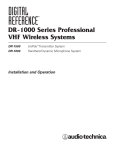
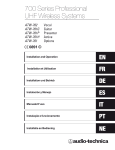
2000 Series Professional
UHF Wireless Systems
ATW-2110 UniPak™ Transmitter System
ATW-2120 Handheld Dynamic Microphone System
Installation and Operation
Professional UHF Wireless Systems
Installation and Operation
This device complies with part 15 of the FCC Rules.
Operation is subject to the condition that this device does
not cause harmful interference.
This device complies with INDUSTRY CANADA R.S.S. 210,
en conformité avec IC: RSS-210/CNR210. Operation
is subject to the following conditions: 1) This device may
not cause harmful interference and 2) this device must
accept any interference received, including interference
which may cause undesired operation.
CAUTION! Electrical shock can result from removal of the
receiver cover. Refer servicing to qualified service personnel.
No user-serviceable parts inside. Do not expose to rain or
moisture.
The versatile ATW-T210 UniPak™ body-pack transmitter has
both low- and high-impedance inputs plus a bias connection,
for use with dynamic and electret condenser microphones,
as well as Hi-Z instrument pickups.
The circuits inside the receiver and transmitter have been
precisely adjusted for optimum performance and compliance with federal regulations. Do not attempt to open the
receiver or transmitter. To do so will void the warranty,
and may cause improper operation.
The ATW-T220 handheld dynamic microphone/transmitter
features the same element used in the PRO 41 dynamic
handheld microphone created for professional live-sound
venues.
Notice to individuals with implanted cardiac pacemakers
or AICD devices:
Any source of RF (radio frequency) energy may interfere with
normal functioning of the implanted device. All wireless
microphones have low-power transmitters (less than 0.05
watts output) which are unlikely to cause difficulty, especially if they are at least a few inches away. However, since a
“body-pack” mic transmitter typically is placed against the
body, we suggest attaching it at the belt, rather than in a shirt
pocket where it may be immediately adjacent to the medical
device. Note also that any medical-device disruption will
cease when the RF transmitting source is turned off. Please
contact your physician or medical-device provider if you have
any questions, or experience any problems with the use of
this or any other RF equipment.
Introduction
Thank you for choosing an Audio-Technica professional wireless
system. You have joined thousands of other satisfied customers
who have chosen our products because of their quality,
performance and reliability. This Audio-Technica wireless
microphone system is the successful result of years of design
and manufacturing experience.
Each 2000 Series wireless system provides a choice of 10 PLLsynthesized UHF frequencies in the 656-678 MHz band (TV
channels 45-48). Each wireless system includes a receiver
and either a body-pack or handheld transmitter. Individual
components are also available separately.
2
The ATW-R2100 receiver features true diversity reception. Two
antennas feed two completely independent RF sections on
the same frequency; automatic logic circuitry continuously
compares and selects the superior received signal, providing
better sound quality and reducing the possibility of interference
and dropouts. Soft-touch controls provide convenient access
to selection of operating frequency and automatic scanning,
while an LCD information display provides constant monitoring
of system operation. The receiver is half-width for a standard
1U 19" rack mount; rack-mount adapters are included. Two
receivers can be mounted side by side, using an optional
AT8630 joining-plate kit.
Transmitters in the 2000 Series use two 1.5V AA batteries for
economical operation and wide availability. Both transmitters
have battery condition indicators.
2000 Series receivers feature a sophisticated Tone Lock™
tone squelch system that opens the receiver’s audio output
only when a 2000 Series transmitter is detected, reducing the
possibility of interference. As a result, 2000 Series transmitters
and receivers must be used together and should not be used
with components from other Audio-Technica wireless systems,
or with those of other manufacturers.
Please note that in multiple-system applications there must be
a transmitter-receiver combination set to a separate channel
(frequency) for each input desired (only one transmitter for
each receiver).
Because the wireless frequencies are within UHF TV frequency
bands, only certain channels (operating frequencies) may be
useable in a particular geographic area. The 10 channels
(operating frequencies) that are used in the 2000 Series have
been selected for multi-channel compatibility. Subject to
frequency availability in a particular geographic area, any of
these 10 channels may be used together.
The operating frequencies that correspond to each of the 10
channels are listed on page 11.
Receiver Installation
Location
For best operation the receiver should be at least 3 ft. (1 m)
above the ground and at least 3 ft. away from a wall or metal
surface to minimize reflections. The transmitter should be at
least 3 ft. from the receiver, as shown in Figure A. Keep
antennas away from noise sources such as digital equipment,
motors, automobiles and neon lights, as well as away from
large metal objects.
Output Connections
There are two audio outputs on the back panel: balanced
(12.5 mV) and unbalanced (25 mV). Use shielded audio cable
for the connection between the receiver and the mixer. If the
input of the mixer is a 1/4" jack, connect a cable from the 1/4"
unbalanced audio output on the back of the receiver housing
to the mixer. If the input of the mixer is an XLR-type input,
connect a cable from the balanced XLR-type audio output on
the back panel to the mixer. The two isolated audio outputs
permit simultaneous feeds to both unbalanced and balanced
inputs. For example, both a guitar amp and a mixer can be
driven by the receiver.
Figure A
Antennas
Attach the included pair of UHF antennas to the antenna input
jacks. The antennas are normally positioned in the shape of a
“V” (both 45° from vertical) for best reception.
Accessory antennas can be remotely located from the receiver.
However, due to signal loss in cables at UHF frequencies, use
the lowest-loss RF cables practical for any cable runs over 25
feet. RG8-type is a good choice. Use only copper-shielded
cable, not CATV-type foil-shielded wire. Audio-Technica offers
quality RF cables in four lengths, as well as remote antennas;
see the Optional System Accessories section on page 10.
Power Connections
Connect the included AC adapter to the DC power input on the
back of the receiver. Loop the small cord from the DC plug over
the cord hook above the jack, to keep the plug from being
detached by an accidental tug on the cord. Then plug the
adapter into a standard 120 Volt 60 Hz AC power outlet.
Operation of the receiver is controlled by the front-panel Power
switch.
(Note: Units supplied to countries with 230V mains should
include an in-line AC adapter appropriate for that country.
Use the included adapter only with 120V 60 Hz AC
power sources.)
3
Receiver Controls and Functions
Figure B-Front Panel Controls and Functions
SET/SCAN
UP
POWER
ON
OFF
UHF SYNTHESIZED DIVERSITY RECEIVER ATW-R2100
5
1
DOWN
2
3
1. POWER SWITCH: Press the Power switch in to turn the
receiver on. The LCD window will light, and the operating
channel number will be displayed in the window. To turn
the receiver off, press the Power switch again.
4
5
Figure C-Receiver LCD Window Display
2. LCD WINDOW: Liquid Crystal Display indicates channel
setting and operational readings. See Fig. C for examples.
3. UP/DOWN BUTTONS: Press Up or Down arrow buttons to
arrive at desired channel. The selected number will flash on
and off. Press and hold Set/Scan button to set the channel
(operating frequency).
4. SET/SCAN BUTTON: Two distinct operations are associated
with this button:
Touch: A momentary press of the Set/Scan button.
7
8
9
6. RF SIGNAL LEVEL INDICATOR: Shows the strength of the
RF signal received from the transmitter.
Hold: A press and hold (about two seconds) of the
Set/Scan button.
7. TUNER OPERATION INDICATOR: Indicates which Tuner
(A or B) has the better reception and is in operation.
The Set/Scan button can be used in two ways: Manual Set
Mode, to permit selection of an operating channel; and
Automatic Scan/Set Mode, to initiate the automatic channel
scan and selection, as follows:
8. CHANNEL DISPLAY: Shows which channel is selected.
Manual Set Mode: After using the Up or Down arrow
button to arrive at desired channel, hold the Set/Scan
button to set the channel. NOTE: Before the channel has
been set, a touch of the Set/Scan button will revert the
channel to its previous setting.
Automatic Scan/Set Mode: Hold the Set/Scan button. The
Automatic Scan/Set Mode will automatically scan for and
set the next open channel.
5. MOUNTING ADAPTERS: For mounting the receiver in any
standard 19" rack. Attach adapters to the receiver with the
screws supplied and remove the four receiver feet. (Use
optional AT8630 joining-plate kit to mount two ATW-R2100
receivers side-by-side.)
4
6
9. AF LEVEL INDICATOR: Shows the audio modulation level
of the received signal.
Receiver Controls and Functions
(Continued)
Figure D-Rear Panel Controls and Functions
18
13
AF
LEVEL
ANT. B
MIN
MAX
ANT. A
SQUELCH
GROUND
AF OUT
GROUND LIFT BALANCED
10
11
12
14
15
12~18V DC
AF OUT
UNBALANCED 500 mA
16
17
10. ANTENNA INPUT JACK: BNC-type antenna connector for
Tuner “B.” Attach the antenna directly, or extend it with a
low-loss antenna cable. See the “Antennas” section on
page 3 for more details.
15. BALANCED AUDIO OUTPUT JACK: XLRM-type connector.
A standard 2-conductor shielded cable can be used to
connect the receiver output to a balanced microphone-level
input on a mixer or integrated amplifier.
11. SQUELCH CONTROL: Adjusts level of noise-muting circuit
(preset at factory but can be adjusted as circumstances
warrant). Factory setting is full counterclockwise.
16. UNBALANCED AUDIO OUTPUT JACK: 1/4" phone jack. Can
be connected to an unbalanced aux-level input of a mixer,
guitar amp or tape recorder.
12. ANTENNA INPUT JACK: Input for Tuner “A.” Attach the
supplied antenna directly, or extend it to an accessory
antenna with a low-loss antenna cable.
17. POWER INPUT JACK: Connect the DC plug from the
included in-line AC adapter.
13. AF LEVEL CONTROL: Adjusts audio output level of both AF
output jacks; maximum output is fully clockwise.
18. CORD HOOK: Loop the small DC cord around the cord
hook to keep the DC plug from pulling out accidentally.
14. GROUND LIFT SWITCH: Disconnects the ground pin of the
balanced output jack (15) from ground. Normally, the switch
should be to the left (ground connected). If hum caused by
a ground loop occurs, slide switch to the right (ground
lifted).
5
Transmitter Controls And Functions
Battery Selection
Two 1.5V AA alkaline batteries are recommended.
UniPak™ Transmitter Battery Installation
1. Open the transmitter door by pressing gently on the
side-cover indentations and pulling back the hinged cover
shown in Fig. E below.
2. Lift the battery-keeper arm, and carefully insert two fresh
1.5V AA alkaline batteries, observing correct polarity as
marked inside the battery compartment.
3. Close the battery-keeper arm.
Handheld Transmitter Battery Installation
1. While holding the upper part of the transmitter body by the
translucant ring below the ball-screen, unscrew the lower
body cover, slide it downward, and remove it to expose the
battery compartment.
2. Observe correct polarity as marked inside the battery
compartment and carefully insert two fresh 1.5V AA
alkaline batteries. Insert the first battery and slide it down.
Then insert the second battery into the space remaining.
Make certain the batteries are fully seated in the battery
compartment. (Fig. F)
3. Slide the lower body cover back up the body, then screw
the housing together. Do not overtighten.
4. Close the transmitter door.
Figure E-UniPak Transmitter Open
Note: Remove batteries from the handheld transmitter starting
at the bottom end, where finger indents in the battery housing
are provided for easy grip.
Figure F-Handheld Transmitter Battery Compartment
Antenna
Screwdriver
Power-on LED
Audio Input Jack
Channel
Selector
Switch
CH
INST
1
9
Instrument/Microphone
Level Trim Controls
LEVEL
MIC
3
7
5
MAX
MAX
Battery Indicator
After the battery is installed, turn on the power switch (located
on the bottom of the handheld transmitter and on the top of the
UniPak transmitter). The battery indicator LED (Fig. G/H) should
turn red. If it does not, the batteries are installed incorrectly or
they are dead.
Figure G-UniPak
Transmitter Top View
Battery Indicator
Battery-keeper
Arm (open);
Screwdriver on
opposite side
Figure H-Handheld
Transmitter Bottom
View
Battery Indicator
POWER
ON
OFF
Transmitter
Door
BATT.
OFF
ON
POWER
ATW-T220
Antenna
Input Connector
Power Switch
Power Switch
UniPak Transmitter Input Connection
Connect an audio input device (microphone or guitar cable) to
the audio input connector on the top of the transmitter. A
number of Audio-Technica professional microphones and cables
are available separately, pre-terminated with a UniPak input
connector (see “Optional System Accessories” on page 10).
6
UniPak Transmitter Antenna
The ATW-T210 UHF transmitter includes one field-replaceable
antenna mounted on the transmitter. The antenna simply
screws into the transmitter’s antenna fitting. Check the installed
antenna occasionally to make certain it is snugly attached (only
finger-tight). If the received signal is marginal, experiment with
different transmitter positions on your body or instrument or try
repositioning the receiver. Do not attempt to modify the
transmitting antenna. Replace it only with the same parts,
available from the Audio-Technica Service Department.
System Operation
The transmitters have a two-position, on-off power switch.
When the switch is “On,” the transmitter produces both RF
and audio.
There is about a half-second delay after the transmitter is
switched to the “On” position before the receiver’s Tone Lock
squelch un-mutes the receiver.
When the transmitter is switched on and in normal operation,
the receiver’s RF signal level indicators will display as dark
segments (signal strength indicators) from bottom to top at the
left side of the LCD display.
Return the screwdriver to its storage clip when not in use.
Figure I-Handheld Transmitter Interior View
Level Trim Control
3
Transmitter On…
Before turning on the transmitter, use the provided screwdriver
to set the transmitter channel selector switches (Fig. E/I) to the
same numbers as those displayed on the receiver. Always turn
the transmitter off when changing channels (frequencies).
CAUTION! The small trimmer controls are delicate; use only
the supplied screwdriver. Do not force the trimmers beyond
their normal 180° range of rotation.
5
To change channel automatically
1. Hold the Set/Scan button. The Automatic Scan/Set Mode
will automatically scan for and set the next open channel.
LCD screen will flash “FS” four times to indicate start of
scan.
Return the screwdriver to its clip and close and secure the lower
body. No further transmitter gain adjustments should
be needed, as long as the acoustic input does not change
significantly.
1
Hold the Set/Scan button until the channel number stops
flashing to set the receiver to the channel indicated.
NOTE: Before the channel has been set, a touch
(momentary press) of the Set/Scan (rather than a hold) will
revert the channel to its previous setting.
7
2
To adjust the transmitter audio input level, unscrew the lower
body cover and slide it downwards, exposing the screwdriver
and level trim control (Fig I). Remove the screwdriver and gently
turn the level trim control counterclockwise until the topmost
receiver AF level meter bar is illuminated only on audio peaks.
9
To change channel manually
1. Use the Up/Down arrow buttons to reach the desired
channel number.
While speaking/singing into the microphone at typically loud
levels, check the AF meter levels on the receiver. If all five AF
meter bars are consistently illuminated and distortion is heard
through the system, it may be necessary to adjust the
transmitter audio input level.
CH
How to Make Operating Channel Changes
Operating channel changes (frequency changes) may be made
in two ways: manually and automatically.
ATW-T220 Handheld Transmitter
The 2000 Series handheld transmitter has factory pre-set audio
input levels. Factory setting is full clockwise, maximum gain.
MAX
Receiver On…
The LCD display will light up and one of the tuner operation
indicator LCD segments (A or B) will light, even though the
transmitter is not on. If two or more of the RF LCD segments
light up at this point, there may be RF interference in the area.
If this occurs, change operating channels (select another
frequency).
Setting Levels
Correct adjustment of transmitter audio input, receiver audio
output, and mixer/amplifier input and output levels is important
for optimum system performance.
LEVEL
Switch on the receiver. Do not switch on the transmitter yet.
Channel
Selector
Switch
Screwdriver
7
System Operation
Setting Levels (Continued)
ATW-T210 UniPak™ Transmitter
Trimmer adjustments in the UniPak™ transmitter (Fig. E) will
enable you to use microphones or instruments with different
output levels.
(Continued)
Figure E-UniPak Transmitter Open
Antenna
1. For MIC: Set microphone level trim control fully
clockwise (maximum) and instrument level trim control
fully counterclockwise (minimum).
Power-on LED
For INSTRUMENT: Set instrument level trim control fully
clockwise (maximum) and microphone level trim control
fully counterclockwise (minimum).
2. Set the receiver’s AF Level control to its full clockwise
position (maximum). See Figure D on page 5.
Audio Input Jack
3. Plug the mic or instrument into the transmitter and power
up the system.
4. For MIC: Make an initial adjustment of the mixer’s level
controls that will allow audio through the system.
Channel
Selector
CH
INST
1
9
Instrument/Microphone
Level Trim Controls
LEVEL
MIC
3
7
5
MAX
MAX
For INSTRUMENT: Make an initial adjustment of the
instrument amplifier input level control that will allow audio
through the system.
5. For MIC: While speaking/singing into the microphone at
typically loud levels, check the AF meter levels on the
receiver. If all five meter bars are consistently illuminated
and distortion is heard through the system, it may be
necessary to adjust the UniPak transmitter audio input level.
To adjust the transmitter audio input level, gently turn the
microphone level trim control counterclockwise until the
topmost receiver AF level meter bar is illuminated only on
audio peaks.
For INSTRUMENT: While playing the instrument at typically
loud levels, check the AF meter levels on the receiver. If all
five meter bars are consistently illuminated and distortion is
heard through the system, it may be necessary to adjust
the UniPak transmitter audio input level. To adjust the
transmitter audio input level, gently turn the instrument
level trim control counterclockwise until the topmost
receiver AF level meter bar is illuminated only on audio
peaks.
6. For MIC: While again speaking/singing into the microphone
at typically loud levels, adjust the mixer’s input trim control
so the highest sound pressure level going into the microphone causes no input overload in the mixer, and yet
permits the mixer’s channel and output level controls to
operate in their “normal” range (not set too high or too
low).
For INSTRUMENT: While again playing the instrument at
typically loud levels, adjust the receiver’s AF Level control
so the highest signal level causes no input overload in the
instrument amplifier and yet permits the amplifier’s input
level controls to operate in their “normal” range (not set
too high or too low).
Note: If the mixer cannot be adjusted to operate in its
normal range without distortion, adjust the receiver’s AF
Level Control (turn counterclockwise) until the mixer/
amplifier is no longer overloaded.
8
Battery-keeper
Arm (open);
Screwdriver on
opposite side
Transmitter
Door
Receiver Squelch
The squelch control on the back panel of the receiver is preset
at the factory for best system performance (factory setting is
full counterclockwise), but can be adjusted if you must use the
system in an area with considerable RF interference. If there is
interference in the audio, and changing the channel is not an
option, adjust the squelch control so the system will receive the
signal from your transmitter but will “squelch” or eliminate the
unwanted background RF noise. This adjustment can cause a
reduction in useable range of the wireless transmitter, so set
the control to the lowest position that reliably mutes the
unwanted RF signals.
RF Interference
Please note that wireless frequencies are shared with other
radio services. According to Federal Communications
Commission regulations, “Wireless microphone operations are
unprotected from interference from other licensed operations in
the band. If any interference is received by any Government or
non Government operation, the wireless microphone must
cease operation...” If you need assistance with operation or
frequency selection, please contact your dealer or
Audio-Technica. Extensive wireless information also is available
on the Audio-Technica Web site at www.audio-technica.com.
Specifications†
OVERALL SYSTEM
Operating Frequency
Number of Channels
Frequency Stability
Modulation Mode
Normal Deviation
Operating Range
Operating Temperature Range
Frequency Response
UHF band, 656.125 to 678.500 MHz
10 total
±0.005%, Phase Lock Loop frequency
control
FM
±5 kHz
300' typical
41° F (5° C) to 113° F (45° C)
100 Hz to 15 kHz
UNIPAK™ TRANSMITTER
RF Power Output
Spurious Emissions
Input Connections
Batteries (not included)
Current Consumption
Battery Life
Dimensions
Net Weight (without batteries)
RECEIVER
Receiving System
Dual independent receivers, automaticswitching diversity
Image Rejection
55 dB nominal, 50 dB minimum
Signal-to-noise Ratio
>100 dB at 40 kHz deviation
(A-weighted), maximum modulation
40 kHz
Total Harmonic Distortion
<1% (±10 kHz deviation at 1 kHz)
Sensitivity
20 dBµV (S/N 60 dB at 5 kHz deviation,
IEC-weighted)
Intermediate Frequency
65.75 MHz, 10.7 MHz
Audio Output (AF Level set at “0”)
Unbalanced:
25 mV (at 1 kHz, ±5 kHz deviation,
100k ohm load)
Balanced:
12.5 mV (at 1 kHz, ±5 kHz deviation,
100k ohm load)
Output Connectors
1
Unbalanced:
/4" phone jack
Balanced:
XLRM-type
Power Supply
120V AC 60 Hz, or 12-18V DC, 350 mA,
with external supply
Dimensions
8.27" (210.0 mm) W x 1.73" (44.0 mm) H
x 6.39" (162.2 mm) D
Weight
2.2 lbs (1.0 kgs)
Accessories Included
Two flexible UHF antennas, rack-mount
adapters, AC adapter
HANDHELD TRANSMITTERS
RF Power Output
Spurious Emissions
Microphone Element
Batteries (not included)
Current Consumption
Battery Life
Dimensions
Net Weight (without batteries)
Accessory Included
†
12 mW
Under federal regulations
High impedance, low impedance, bias
Two 1.5V AA alkaline
150 mA typical
Approximately 9 hours (depending on
battery type and use pattern)
2.60" (66.0 mm) W x 3.63" (92.3 mm) H
x 0.89" (22.5 mm) D
2.82 oz (80 g)
12 mW
Under federal regulations
Dynamic, unidirectional
Two 1.5V AA alkaline
150 mA typical
Approximately 9 hours (depending
on battery type and use pattern)
9.02" (229.0 mm) long x 2.11" (53.5 mm)
maximum diameter
7.81 oz (221.5 g)
AT8456a Quiet-Flex™ stand clamp
In the interest of standards development, A.T.U.S. offers full details on its test methods to
other industry professionals on request.
Specifications are subject to change without notice.
9
Optional System Accessories
WIRELESS ESSENTIALS MICROPHONES AND CABLES
AT829cW
Miniature cardioid condenser lavalier microphone.
Includes clothing clip and windscreen.
MT830cW
Miniature omnidirectional condenser lavalier
microphone. Includes clothing clip and windscreen.
MT830cW-TH “Theater” model, same as MT830cW except beige color
mic and cable for concealment.
AT831cW
Miniature cardioid condenser lavalier microphone.
Includes clothing clip and windscreen.
™
AT889cW
Headworn noise-canceling condenser microphone.
Includes windscreen and cable clip.
AT898cW
Subminiature cardioid condenser lavalier microphone.
Includes clothing clip base, viper clip base, magnet clip
base,three single mic holders, two double mic holders and
two windscreens.
AT899cW
Subminiature omnidirectional condenser lavalier microphone.
Includes AT899AK accessory kit.
AT899cW-TH “Theater” model, same as AT899cW except beige color mic
and cable concealment. Includes AT899AK-TH accessory kit.
ATM35cW
Cardioid condenser instrument microphone.
Includes AT8418 clip-on instrument mount.
ATM73cW
Headworn cardioid condenser microphone.
Includes windscreen.
ATM75cW
Headworn cardioid condenser microphone.
Includes windscreen.
PRO 8HEcW Headworn hypercardioid dynamic microphone.
Includes windscreen and cable clip.
PRO 35xcW Cardioid condenser instrument microphone.
Includes AT8418 clip-on instrument mount.
AT-GCW
Hi-Z instrument/guitar cable with 1/4" phone plug.
XLRW
Connecting cable for UniPak transmitter with an XLRF-type
input connector, for Lo-Z microphones with XLRM-type
output terminations.
RECEIVER ACCESSORIES
AEW-DA660D UHF (655-680 MHz) active unity-gain antenna distribution
system provides two “1-in, 4-out” RF channels; connects a
pair of antennas to as many as four diversity receivers;
cascade output provided as a directional coupler. AC
pass-through allows daisy-chain AC hookup. Defeatable
antenna power. Metal receiver chassis with reinforced
mounting ears and rear rack mount capability. Includes
detachable IEC power cable, IEC pass-through cable, ten RF
cables, front-mount antenna cables and connectors, four DC
power cables to power up to four 2000 Series receivers.
Mounts in a single 19" rack space.
AT8630
Joining-plate kit allows rack-mounting two ATW-R2100
receivers side-by-side in a single (1U) 19" rack space.
ATW-A20
Pair of UHF ground-plane antennas with 5/8"-27 thread for
mounting to microphone stands, etc. For use with
ATW-R2100 receivers. Takes RF cables with BNC
connectors, not included; see RF Cables below.
ATW-A49
Pair of UHF wide-band directional LPDA (log periodic dipole
array) antennas provide enhanced signal pickup for UHF
wireless systems throughout a wide band range
(440-900 MHz). Each antenna paddle is matched to 50 ohms
impedance with intergral high-quality low-loss BNC connector;
6 dB gain. For permanent or temporary installation; mounts
to 5/8"-27 threads.
ATW-RA1
Rack-mount antenna kit brings antenna inputs to the front of
receiver for ease of setup, or when receiver is enclosed in a
metal rack. Includes a pair of extendible antennas. NOTE:
Two adapter kits are required when mounting two receivers
side-by-side in a single 19" rack space.
RF Cables
Low-loss design, 50 ohm impedance, with BNC-to-BNC
connectors:
AC12
RG58-type cable (12')
AC25
RG8-type cable (25')
AC50
RG8-type cable (50')
AC100
RG8-type cable (100')
TRANSMITTER ACCESSORIES
AT8114
Foam windscreen for handheld transmitter.
AT8141
Water-resistant pouch for UniPak transmitter.
AT8456a
10
Quiet-Flex™ stand clamp for handheld transmitter, 5/8"-27
threads.
2000 Series Frequency Channel Plan
Channel
Frequency - MHz
TV Channel
1
2
3
656.125
659.375
660.000
45
4
5
662.125
665.125
46
6
7
669.750
671.500
47
8
9
10
677.000
678.125
678.500
48
Note: All frequencies selected to avoid standard analog TV
carrier interference.
Ten Tips to Obtain the Best Results
2. Position the receiver so that it has the fewest possible
obstructions between it and the normal location of the
transmitter. Line-of-sight is best.
7. If the AF Level control of the receiver is set too high, it
may over-drive the input of the mixer or clip the output of
the receiver, causing distortion. Conversely, if the receiver
output is set too low, the overall signal-to-noise ratio of
the system may be reduced. Please see Setting Levels
section, pages 7 and 8.
3. The transmitter and the receiver should be as close
together as conveniently possible, but no closer than
three feet (1 m).
8. You need to change channels when a strong interference
signal is received (a strong RF signal is shown with the
transmitter off).
4. The receiver antennas should be in the open and away
from any metal. If mounted in a rack, have the unit on
top, or use an ATW-RA1 kit to front-mount the antennas.
9. In the UniPak transmitter, the microphone level trim or
instrument level trim input control not in use should be
set to minimum.
5. The transmitter and receiver must be set to the same
channel number.
10. Turn the transmitter off when not in use. Remove the
battery if the transmitter is not to be used for a period of
time.
1. Use only fresh alkaline batteries. Do not use “general
purpose” (carbon-zinc) batteries.
6. A receiver cannot receive signals from two transmitters
at the same time.
For future reference, please record your system information here.
Receiver
ATW-R2100
S/N
Serial Number appears on the FCC label on the back of the receiver.
UniPak™ Body-Pack
Transmitter
ATW-T210
Handheld Dynamic
ATW-T220
Microphone Transmitter
S/N
Serial Number appears on the FCC label on the back of the transmitter.
S/N
Serial Number appears on the FCC label on the interior of the transmitter.
11
One-Year Limited Warranty
Audio-Technica professional wireless systems purchased in the U.S.A. are warranted for one year from date of purchase by Audio-Technica U.S., Inc.
( A.T.U.S.) to be free of defects in materials and workmanship. In event of such defect, product will be repaired promptly without charge or, at our
option, replaced with a new product of equal or superior value if delivered to A.T.U.S. or an Authorized Service Center, prepaid, together with the
sales slip or other proof of purchase date. Prior approval from A.T.U.S. is required for return. This warranty excludes defects due to normal wear,
abuse, shipping damage, or failure to use product in accordance with the instructions. This warranty is void in the event of unauthorized repair or
modification, or removal or defacing of the product labeling.
For return approval and shipping information, contact the Service Dept., Audio-Technica U.S., Inc., 1221 Commerce Drive, Stow, Ohio 44224.
Except to the extent precluded by applicable state law, A.T.U.S. will have no liability for any consequential, incidental, or special damages; any
warranty of merchantability or fitness for particular purpose expires when this warranty expires.
This warranty gives you specific legal rights, and you may have other rights which vary from state to state.
Outside the U.S.A., please contact your local dealer for warranty details.
Visit our Web Site!
www.audio-technica.com
Audio-Technica U.S., Inc., 1221 Commerce Drive, Stow, Ohio 44224 330/686-2600 www.audio-technica.com
P#2323-03250
P51719 ©2004 Audio-Technica U.S., Inc. Printed in Malaysia