1
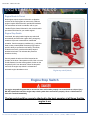
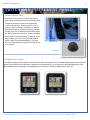
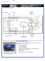
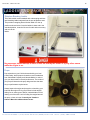
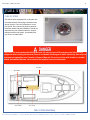
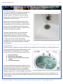
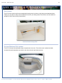
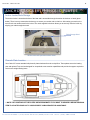
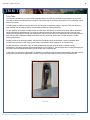
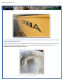
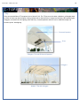
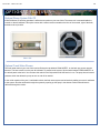
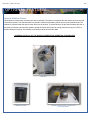
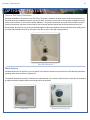
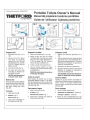
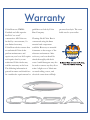
Model Year 2012
1
C O B IA 237
O
w
n
e
r
’
s
M
a
n
u
a
WELCOME
Dear New Cobia Owner,
On behalf of Cobia Boats, I would like to congratulate
you on your purchase. We at Cobia strive to build the
best products possible and wish you years of trouble
free enjoyment. There are many things to know about
the operation, care and maintenance of our products
and the systems we install in them. Please review all
the applicable information for your new boat. The more
you know, the more you will enjoy your new Cobia.
Again, a heartfelt Thank You from myself and the whole
Cobia Family.
Scott Deal, President and CEO
Maverick Boat Company, Inc.
• 3207 Industrial 29th St. • Fort Pierce,
Florida 34946 • (772)-465-0631 or (888)-shallow • Fax: (772) 489-2168
l
Model Year 2012
2
T A B L E O F C O NT E NT S
Specifications...............................................................................2
Yamaha Engine Break-In Periods................................................3
Engine Stop Switch......................................................................3
Optional Command Link Gauges...........................................20
Optional Salt Water Washdown..............................................21
Optional Waste System.....................................................21-24
Instrument Panel with Yamaha Multi-Function
Gauges.........................................................................................4 Warranty.................................................................................25
Switch Panels...............................................................................4
Switch Panels & Helm..................................................................4
216 Boat Layout...........................................................................5
Cobia Duffel Bag..........................................................................5
Fuel/Water Separators.................................................................6
Garboard Drain Plug....................................................................6
Bilge System................................................................................7
Ball Valves, Thru Hull Fittings, & Scuppers..................................8
Cockpit Courtesy Lights...............................................................9
Stainless Boarding Ladder.........................................................10
Props..........................................................................................10
Fuel System...............................................................................11
Self Bailing Cockpit....................................................................12
237 SPECIFICATIONS
Livewell System.........................................................................12
L.O.A............................................................23’ 07”
Rod Lockers...............................................................................13
BEAM.............................................................8’ 10”
Forward Storage........................................................................13
DRAFT................................................................17”
Anchor Locker / Rode Storage...................................................14
WEIGHT W/O ENGINE..........................3600 LBS.
237 Plate Location.....................................................................14
Trim Tabs...................................................................................15
FUEL CAPACITY......................................129 GAL.
Battery Switch/Dual Battery System..........................................16
DEADRISE @ TRANSOM.......................21.5 DEG
MAXIMUM
Wiring Color Codes....................................................................17
MAXIMUM H.P..................................................300
Optional Bow Cushion Set.........................................................18
TRANSOM HEIGHT……30” SINGLES 25”TWINS
Optional T-Top............................................................................19
MAXIMUM CAPACITIES…………………..…..8
PERSONS OR 1700 LBS
Optional Stereo System.............................................................20
Maverick Boat Company, Inc.
• 3207 Industrial 29th St. • Fort Pierce,
Florida 34946 • (772)-465-0631 or (888)-shallow • Fax: (772) 489-2168
Model Year 2012
3
ENG INE B RE A K - IN P E RI OD
Engine Break-In Period
New engines require a period of break-in to allow the
surfaces of the moving parts to mate evenly. Different
engines require different break-in periods and methods.
For instructions on break in methods, refer to your
Yamaha Engine Owner’s Manual for the correct break-in
procedures and times for your model engines
Engine Stop Switch
If activated, the spring loaded engine stop switch will
automatically shut down the engine during emergency
situations to prevent uncontrolled or unattended
operation. Certain emergency conditions (e.g., turbulent
water, wakes, unanticipated movement) may impair a
person’s ability to operate the craft safely. The switch,
located on the helm, must have the safety lanyard
attached at its base. This activates the protective
shutdown circuitry.
Securely attach the other end of the lanyard to the
operator of the boat. If the operator moves, falls or is at an
unsafe distance from the steering wheel, tension on the
lanyard will pull it from the switch. When the lanyard is
removed, the engine stop switch is released and
automatic engine shutdown occurs.
Engine stop switch (above)
Engine Stop Switch
An engine stop switch system that is not used or does not function properly can cause death or serious injury.
DO NOT operate the boat if the engine stop switch system does not function properly. Go to a Cobia Dealer to
have this resolved immediately
The lanyard should be securely attached to the boat operator at all times that the
engine is on.
Maverick Boat Company, Inc.
• 3207 Industrial 29th St. • Fort Pierce,
Florida 34946 • (772)-465-0631 or (888)-shallow • Fax: (772) 489-2168
Model Year 2012
4
SW I T CH AND I NST R UM ENT PANEL
Switch Panel & Helm
At the helm of your Cobia, you have a main switch
panel, which is located to the left of the steering wheel.
This panel controls your lights, horn, accessories,
livewell, and your bilge. When a switch is in the “on”
position, its tip is illuminated. This alerts you that the
associated accessory should be functioning and also
reminds you to turn it off during boat shutdown. When
the “NAV” light switch is in the “on” position, the labels
for the switches will be illuminated. To the right of the
steering wheel you have your two trim tab switches
(Refer to page 23 for trim tab operation.) The boat
also comes standard with a compass mounted on top
of the console.
Switch Panel
Compass
Command Link Gauges
Command Link gauges come standard on the Cobia 237 and are an upgrade from the standard digital gauges. Command Link
gauges allow access to more information. Displays are user-selectable so you can choose the functions displayed on each
gauge and what order. Speed data can be displayed from a pitot tube, Triducer or NMEA protocol GPS unit.
Maverick Boat Company, Inc.
• 3207 Industrial 29th St. • Fort Pierce,
Florida 34946 • (772)-465-0631 or (888)-shallow • Fax: (772) 489-2168
Fish Box
Model Year 2012
5
BOAT LAYOUT
327 Boat Layout
Boarding Ladder
Insulated and
Drainable
Storage
Fish Box
Livewell
Anchor Locker
In-Deck Storage
Fish Box
Seating/Systems Access
Console With Optional
Head Space
Insulated and
Drainable
Storage
Cobia Duffel Bag
Along with your boat, you received a Duffel Bag with your new Cobia. Inside
the Duffel Bag are the following items:
• Large Livewell Standpipe
• Short Livewell Standpipe
• 1.5” Livewell Pacifier Plug
• 2 ignition Keys and Emergency Kill Cord /Engine Stop Lanyard
• Yamaha Engine Owner’s Manuals
• Engine Start Cord
• Various Appliance and Accessories Manuals
Cobia Duffel Bag
Maverick Boat Company, Inc.
• 3207 Industrial 29th St. • Fort Pierce,
Florida 34946 • (772)-465-0631 or (888)-shallow • Fax: (772) 489-2168
Model Year 2012
6
F U E L -W A T E R SE P A R A T O R & D R A I N P L U G
Fuel-Water Separator
A Yamaha Fuel - Water Separator is installed behind
the aft seat assembly. Simply lift up the seat and you
will be able to easily access the Fuel-Water
separator. The new, improved 10-micron filter
provides superior filtration ahead of the engine's onboard filters and injectors. Large filtering and water
capture areas maximize filtration while maintaining
adequate flow rate for larger engines. The fuel
separator can be checked by removing it from the
mounting bracket and dumping it into an approved
waste collection device. If there appears to be an
excessive amount of water, the filter component
should be replaced. See your authorized Cobia
Dealer for replacement parts.
Fuel/Water Separator
Maintenance Note
Yamaha recommends replacing the 10- micron fuel filter on new boats after the first 10 hours or 1 month of
operation and every 50 hours or every 6 months thereafter. In areas of hight humidity where water in fuel supplies is a
problem or extensive engine operation occurs, more frequent replacement may be necessary.
Garboard Drain Plug
The garboard drain plug is the small metal plug located at
the lowest point on the hull, at the bottom of the transom
right above the keel. The drain has been designed to so
that it can be loosened by hand while the hull is out of the
water for draining. This allows the plug to stay in contact
with the surrounding frame so you’ll never misplace or
lose it. You can completely remove the insert by pulling
back and continue turning in a counter clockwise motion.
It is manufactured with a rubber seal in place to ensure
you bilge is watertight. Always make sure before putting
the boat in the water that this plug is hand tightened
firmly. Excess water in the bilge may be an indication of a
problem with this plug or the automatic bilge pump. Refer
to page 7 of this Owner’s Manual for information on your
boats bilge system.
Maverick Boat Company, Inc.
• 3207 Industrial 29th St. • Fort Pierce,
Florida 34946 • (772)-465-0631 or (888)-shallow • Fax: (772) 489-2168
Model Year 2012
7
B I L GE
Bilge
The bilge of your Cobia should always be checked before
and after a launch. While checking the bilge, note that a
small amount of water in the bilge is normal. However, a
large amount of water or any signs of fuel or oil requires
immediate attention. If such a situation exists, the boat
should be taken to a certified marine technician
immediately. Never pump fuel or oil overboard while
your boat is in the water.
Large quantities of water in the bilge may be an
indication of a leak or that the bilge pump and/or
automatic float switch is not functioning properly due to a
jam, clog or electrical issue. The automatic float switch is
wired to the hot side of the battery switch through the
“BILGE” fuse at the battery switch panel. When
functioning properly, the float switch activates the bilge
pump to pump water overboard once water in the bilge
reaches a level that submerges the switch.
If your bilge pump does not come on when the float
switch is submerged, attempt to manually turn on the
bilge pump on your switch panel. If the bilge pump comes
on and evacuates the water, it is clear that the float
switch is not functioning properly. If the bilge pump does
not come on via the switch panel, check the breaker
panel inside the console to see if a breaker has been
tripped. If the breaker has been tripped, reset it, and turn
the switch on again, listening for the bilge pump to turn
on.
Bilge Pump
Automatic Float Switch
If the bilge pump fails to turn on, turn the battery switch to the OFF position, then unhook the bilge pump from its cradle
by pressing down on the blue tabs on the cradle and gently turning the top of the pump. You will feel the pump release
from the cradle. The entire bilge pump and wiring should release from the cradle. After removing the pump, check the
underside and impeller areas for miscellaneous items that might clog the pump. If any obstructions are present remove
the debris and set the pump back into the cradle. Once set back in the cradle, press the blue tab down and rotate the
pump until you feel it snap back in place. Once this is completed you can try to turn the pump on again.
If the bilge pump still does not turn on, it likely needs to be replaced. It is not recommended to use your boat if the bilge
pump and/or float switch are not functioning properly.
Maverick Boat Company, Inc.
• 3207 Industrial 29th St. • Fort Pierce,
Florida 34946 • (772)-465-0631 or (888)-shallow • Fax: (772) 489-2168
Model Year 2012
8
SYST EM S
Ball Valves
Ball valves can be used to serve several purposes. They
allow seawater to enter the boat, in the case of livewells,
and they also act as a safeguard to stop water from
entering. To tell which position a ball valve is in, open or
closed, look at the valve and determine the direction of
flow. When the ball valve handle is in the same position
as the direction of flow, the valve is in the “OPEN”
position. When the ball valve handle appears to cross the
direction of flow, the valve is in the “CLOSED” position.
237 Deckdrain System
The deckdrain system is equipped with 1 1/2” thru hull
fittings through the aft port and starboard hull sides.
These fittings have to be installed lower than the drains in
the cockpit floor so that gravity will allow the cockpit to
drain free of water. This puts these fittings very close to
the water line of the hull. These drains are rigged with ball
valves that can be opened and closed to control the flow
of water. In the open position, these ball valves will allow
water to flow freely from the cockpit, thus making the boat
“self-bailing”. When closed, no water will be allowed to
travel to or from the cockpit.
Water Flow
237 Livewell Pump Assembly
The livewell pump assembly is composed of a scoop
strainer mounted to the bottom of the hull, a thru hull
fitting, ball valve assembly, and the pump. As you can
see, the ball valve assembly is in the “OPEN” position.
This is the correct position for the operation of the livewell
system.
THE LIVEWELL PUMP
ASSEMBLY IN THE
“OPEN” POSITION
Maverick Boat Company, Inc.
CLOSED
• 3207 Industrial 29th St. • Fort Pierce,
Florida 34946 • (772)-465-0631 or (888)-shallow • Fax: (772) 489-2168
Model Year 2012
9
COCKPIT COURTESY LIGHTS
Cockpit Courtesy Lights
The cockpit comes equipped with three L.E.D. courtesy lights installed at the factory. These lights illuminate the entire
cockpit and are controlled by the switch panel. The switch labeled “COCKPIT LTS” controls the courtesy lights. The courtesy
lights are mounted beneath the port and starboard gunnels as well as at the bow, aft of the anchor locker.
Diagram of the LED Cockpit Courtesy Lights
Battery Switch
The switch is located at the aft starboard cockpit. On a single battery system, your battery is wired to the number 1 side of
the switch. On the optional dual battery setup, one battery is wired to the number one position while the second battery is
wired to the number 2 side of the switch. The operator can choose which battery to utilize by the selection on the switch. The
only time the switch should be in the “1 & 2” position is if one battery will not start the engine. Then, switch to “1 & 2” and
have two batteries start the engine.
Battery Switch, Shown in the “Off” Position
Maverick Boat Company, Inc.
• 3207 Industrial 29th St. • Fort Pierce,
Florida 34946 • (772)-465-0631 or (888)-shallow • Fax: (772) 489-2168
Model Year 2012
10
L A D D E R A N D PR O PS
Stainless Boarding Ladder
This Cobia model comes standard with a telescoping stainless
steel boarding ladder integrated into the port aft platform area.
This provides a stepping area while the ladder is in the up
position as shown below. Once the ladder is down and in the
extended position, close the lid cover for safe and secure entry
and exit via the
ladder.
No passenger should attempt to enter or exit the boat by the ladder or by any other means
while the engine is on.
Props
Prop selection on your Cobia is determined by your local
Cobia Dealer, but all props are based on recommendations
from Cobia Boat Company and Yamaha Marine in order to
give your boat maximum overall performance. The needs of
your prop will determine the prop design and size that best
fits your performance requirements.
Always inspect the engine and prop prior to launching your
boat with the engine off. Key prop issues include tangled
fishing line or other types of debris, cracked blades or fluid
leaking out of the seal. Look for fishing line tangled around
the prop or lower unit seal. Consult your Yamaha’s
Owner’s Manual to address these issues.
Maverick Boat Company, Inc.
• 3207 Industrial 29th St. • Fort Pierce,
Florida 34946 • (772)-465-0631 or (888)-shallow • Fax: (772) 489-2168
Model Year 2012
11
F U E L SY ST E M
FUEL SYSTEM
This Cobia comes equipped with a 129-gallon fuel
cell stationed below the leaning post between the
stringer system. The fuel fill receptacle is on the
port gunnel. Every fuel tank is pressure tested at
the factory before and after installation. Should you
experience any fuel related problems or suspect
problems with the fuel system, immediately take
your boat to a Cobia Dealer.
CAUTION—Do not smoke while filling the tank. Be sure to turn off the engines and all electrical
equipment when fueling the boat to prevent accidental discharges of static electricity. Use only the
recommended gasoline (see Yamaha’s Owner’s Manual). Do not use fuels with alcohol or alcohol
related derivatives that can cause marine fuel system hoses to deteriorate.
Fuel Fill
Fuel Filter
Primer Ball
Fuel Tank
FUEL SYSTEM DIAGRAM
Maverick Boat Company, Inc.
• 3207 Industrial 29th St. • Fort Pierce,
Florida 34946 • (772)-465-0631 or (888)-shallow • Fax: (772) 489-2168
Model Year 2012
12
SEL F -B AI L I NG COCKPI T & L I VEW EL L SYST EM
Self Bailing Cockpit
The cockpit is designed to be self-bailing, meaning that all
the water that comes into the cockpit will be directly
drained overboard. This keeps the boat from acquiring
standing water and allows the boat to drain at all times,
including while the boat is docked.
Water drains out of the cockpit through two aft cockpit
drains located at the far aft cockpit floor on both the port
and starboard sides. Each side drains overboard through
the side of the hull independently. None of this water is
drained into the bilge. Refer to page 8 for operation of the
ball valve associated with this system.
The bilge is designed to drain any water entering the
inside of the hull. All hoses are sealed and double
clamped during construction. Continuous or periodic
running of the automatic bilge pump may be an indication
of a hose leak or break in a seal, and should be
investigated by a Cobia Dealer immediately. Refer to page
9 for further information regarding bilge pump operation
and maintenance.
Livewell System
The livewell system is designed to keep your baitfish alive and strong for as long as possible. This livewell provides a cool,
clean, and oxygenated environment that allows you to keep
your baitfish alive for long periods of time. To efficiently
operate your livewell, the following steps should be taken:
1. Open livewell hatch.
2. Install stand-up pipe snugly.
3. Ensure livewell pump ball valve is in open
position.
4. Turn on livewell switch.
The livewell operates by pumping fresh seawater from the
pump through an aerator head into the livewell. Drainage is
achieved through the grate on the top of the standpipe,
which, when unobstructed, will limit the water level to the
standpipe’s highest point. A shorter standpipe can be used to
keep less water in the well. This constant drainage keeps up water flow and allows for the removal of ammonia from the
livewell, therefore extending the life of your baitfish. To drain the livewell, switch off the pump, close pump ball valve, and
remove standpipe.
Maverick Boat Company, Inc.
• 3207 Industrial 29th St. • Fort Pierce,
Florida 34946 • (772)-465-0631 or (888)-shallow • Fax: (772) 489-2168
Model Year 2012
13
R O D L O C KE R S & F I SH L O C KE R S
Rod Lockers
The 237 center console model comes standard with under gunnel rod racks on both the port and starboard sides.
These give you space to safely store an additional 6 rods for your fishing needs. These lockers can also double as
storage for various other items (as seen below).
Starboard Gunnel Storage Rack
Port and Starboard Fish Lockers
The 237 CC has port and starboard storage compartments in the bow. These lockers are insulated and drain
overboard through independent thru hulls on each side of the hull just below the boxes.
Maverick Boat Company, Inc.
• 3207 Industrial 29th St. • Fort Pierce,
Florida 34946 • (772)-465-0631 or (888)-shallow • Fax: (772) 489-2168
Model Year 2012
14
ANCHOR LOCKER/ PHENOLIC PLATES
Anchor Locker/Rode Storage
The anchor locker is located at the bow of the boat and is accessible through the anchor locker door or hatch (photo
below). There is an eye mounted to the bow eye to secure your anchor rode or chain to. After setting your anchor, the
excess rode can remain stored in the locker. The notch supplied in the door allows you to securely close the locker by
aligning your rode through the notch.
Rode Storage Notch
Anchor locker with optional windlass shown
Phenolic Plate Location
Your Cobia 237 comes standard with phenolic plates laminated into the cockpit floor. These plates secure the leaning
post and optional T-top and are designed for exceptional screw retention capabilities and provide the support required to
secure such weight bearing items.
** NOTE THE LOCATIONS OF THE PLATES ARE APPROXIMATE. IF YOU WANT TO SECURE A WEIGHT BEARING
ITEM TO A PLATE PLEASE GO TO YOUR NEAREST COBIA DEALER FOR ASSISTANCE
Maverick Boat Company, Inc.
• 3207 Industrial 29th St. • Fort Pierce,
Florida 34946 • (772)-465-0631 or (888)-shallow • Fax: (772) 489-2168
Model Year 2012
15
TRIM TABS
Trim Tabs
Trim Tabs are standard on your new Cobia. Integrated electric trim tabs can enhance the performance of your boat.
The tabs are electric and therefore do not require a trim tab pump. By not having a pump there is no possibility of fluid
leaks from a pump.
Trim tabs allow for maximum boat performance, and are great for balancing weight in the boat. They also allow the
boat operator to lift or lower the hull to accommodate for different running situations.
For the operation of trim tabs note that the port trim tab switch will affect the port side of the boat, and the starboard
switch will affect the starboard side. For instance, lowering the port trim tab creates stern lift on the port side, thus
lowering the starboard bow. Raising the starboard trim tab lowers the stern on the starboard side, thus raising the port
bow. Use the tabs to adjust the attitude of the boat so that it sits evenly, and to raise or lower the bow to control
running performance.
Pushing on the top of the switch (down), will lower the trim tab and force the bow down, which is important when
running in heavy seas or a stiff chop. In most cases, both tabs should be lowered for an even bow ride.
Pushing the bottom of the switch (up), will raise the tabs lifting the bow out of the water, for better running
performance. To achieve the best running performance of your Cobia 217, use the engine trim in conjunction with your
trim tabs to find the appropriate amount of lift for a safe and comfortable ride.
In the event of rough water or high winds, it’s possible to use the trim tabs to lift the windward side of the boat to avoid
spray blowing back onto the passengers. Do this in conjunction with lowering the bow on the downward side.
Trim Tab
Maverick Boat Company, Inc.
• 3207 Industrial 29th St. • Fort Pierce,
Florida 34946 • (772)-465-0631 or (888)-shallow • Fax: (772) 489-2168
Model Year 2012
16
Model Year 2012
17
OPTIONAL FEATURES
Optional Features
Optional Bow Cushion Set
The 237 CC comes with the option of a six-piece bow cushion set. These cushion bottoms are removable and are held in
place by several sets of stainless steel snaps. To remove the cushions, simply pull the snap strap away from the
embedded snap and remove and store the cushion
3
2
6
4
1
Bow Cushion Options
5
Model Year 2012
18
T -T O PS
T-Top
There are several different T-Top options for the Cobia 237 CC. The T-Tops come with either a Weblon or a fiberglass hard
top. Each of these tops has the option of being outfitted with an electronics box, forward and aft facing LED spreader lights,
outriggers, recessed multi color lighting (white and blue), recessed speakers and an E box for additional storage and
electronic space. downlighting
Recessed Speakers
E box
Fiberglass T-Top with E Box and Speakers
Outriggers
Weblon T-Top with Outriggers
Model Year 2012
19
OPTIONAL FEATURES
Optional Stereo System With CD
A AM-FM Stereo CD with four speakers is offered as an option on your new Cobia. The stereo unit is mounted inside the
console on the aft bulkhead. This option comes with a stereo remote mounted on the face of the console, right of the helm,
and above the cup holder.
Stereo Unit
Stereo Remote
Optional Fresh Water Shower
The fresh water tank on your new Cobia can be filled at the cap labeled “RAW WATER”, on the back port corner near the
transom. The hose nozzle is on the port aft bulkhead. To pressurize the system, flip the switch labeled “FRESHWATER” on
the switch panel at the helm. You can leave this switch in the ON position while the boat is in use. The pump has an internal
pressure switch that allows the pump to turn on and off as needed.
In the colder months of the year, it’s advisable to drain the fresh water system and winterize by adding a non-toxic antifreeze
to the system. Run the antifreeze through the system by opening up the spray in the shower nozzle until antifreeze is
delivered through the nozzle.
Model Year 2012
20
OPTIONAL FEATURES
Optional Windlass Deluxe
The windlass is used to lower and raise your anchor assembly. The switch is mounted at the helm station above to the right
of the steering wheel. The solenoid switch is mounted to aft hull and the battery cables are run up the starboard side. The
windlass is mounted inside the anchor locker at the bow of the boat. To access this area, lift the anchor hatch at the bow. A
bow plate and anchor roller has been added to accept the anchor and keep it far enough from the bow of your 237CC to
prevent damage to the bow. The windlass is mounted just aft of the bow roller plate.
**WARNING: READ ALL OF THE INSTRUCTIONS BEFORE OPERATING THE WINDLASS
Windlass
Windlass Switch
Windlass anchor roller, as seen from
the anchor locker
Model Year 2012
21
OPTIONAL FEATURES
Optional Salt Water Washdown
Salt-water washdown is an option on your new Cobia. The pump is located in the bilge forward of the livewell pump and is
accessible through the splashwell hatch or the aft port hatch. To operate, hook a hose to the raw water receptacle in the aft
section of the rod locker. Flip the switch labeled “Saltwater”. The pump will pressurize the system with raw water. Once the
system is pressurized, the pump will shut itself off with an internal pressure switch and will switch itself back on as you
demand water. Be careful to only spray gel-coated fiberglass surfaces with saltwater and avoid all other areas. Always rinse
your boat with freshwater as soon as you return to the dock or home if the boat is being trailered.
Raw Water Receptacle
Waste System
A portable head unit is an option for your new Cobia. The instruction manual can be found in the Cobia duffel bag and basic
operating instructions are listed on pages 22-24.
The optional head pump out fitting is located on the starboard side of the console. With this option, waste can be removed at
an approved dumping station without removing the tank from the head.
Porta Potty
Waste Removal Fitting, Top
Warranty
Cobia Boats are NMMA
Certified and offer superior
guidelines set forth by Cobia
Boat Company.
SeaTech “no wood”
construction. All Cobias are
Cleaning: Each Cobia Boat is
backed by a no-nonsense, 10year limited warranty.
constructed using the finest
material and components
Cobia Boats advises owners that
an authorized Cobia dealer
available. However, no material
is immune to the ravages of the
perform maintenance and
saltwater environment. After
repairs on your boat. Self repairs each use, your boat should be
and repairs done by a nonauthorized Cobia dealer may
rinsed thoroughly with fresh
water. A mild detergent may also
void the warranty on the boat.
The following information is
be used to remove any dirt, silt or
stains. A light coat of lubricants
general in nature and should not on metal railing, screws, and
be considered a repair manual or electrical connections will help
prevent electrolysis. The same
holds true for your trailer.