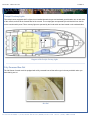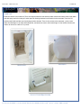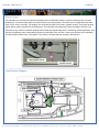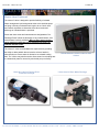
1
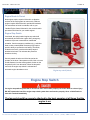
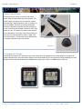
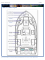
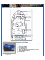
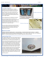
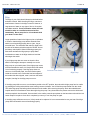
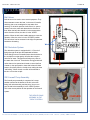
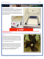
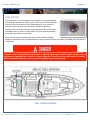
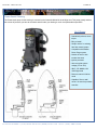
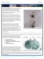
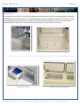
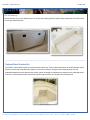
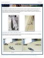
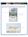
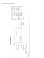
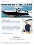
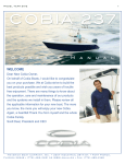
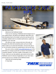
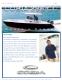
Model Year 2014
page 1
C O B IA 2 96 CC
O
w
n
e
r
’
s
M
a
n
u
a
WELCOME
Dear New Cobia Owner,
On behalf of Cobia Boats, I would like to congratulate
you on your purchase. We at Cobia strive to build the
best products possible and wish you years of trouble
free enjoyment. There are many things to know about
the operation, care and maintenance of our products
and the systems we install in them. Please review all
the applicable information for your new boat. The more
you know, the more you will enjoy your new Cobia.
Again, a heartfelt Thank You from myself and the whole
Cobia Family.
Scott Deal, President and CEO
Maverick Boat Company, Inc.
• 3207 Industrial 29th St. • Fort Pierce,
Florida 34946 • (772)-465-0631 or (888)-shallow • Fax: (772) 489-2168
l
Model Year 2014
page 2
TA BLE O F C O NTENTS
Specifications...............................................................................2
Yamaha Engine Break-In Periods................................................3
Engine Stop Switch......................................................................3
Freshwater System.................................................................24
Battery Switch/Dual Battery System.......................................25
Battery Charger......................................................................26
Instrument Panel with Yamaha Multi-Function
Gauges.........................................................................................4 Leaning Post and Tackle Station ...........................................27
Switch Panels...............................................................................4 Aft Seating..............................................................................28
Switch Panels & Helm..................................................................4 Optional Bow Cushion Set......................................................28
296 Boat Layout........................................................................5-6 Cockpit Bolsters......................................................................29
Cobia Duffel Bag..........................................................................6 Pop-up Bow Light, Cleats, and Rope Chocks........................29
Fuel/Water Separators.................................................................7 T-Top Options.........................................................................30
Garboard Drain Plug....................................................................7 Kite/Rod Holders....................................................................31
Bilge System................................................................................8 Optional Stereo System..........................................................32
Bilge Access.................................................................................9 Optional Windlass System................................................32-33
Ball Valves, Thru Hull Fittings, & Scuppers................................10 Wiring System Diagrams...................................................34-39
Cockpit Courtesy Lights.............................................................11 Warranty.................................................................................40
Head Systems.......................................................................12-14
Stainless Boarding Ladder.........................................................15
Props..........................................................................................15
296 SPECIFICATIONS
Fuel System...............................................................................16
L.O.A............................................................29’ 07”
Steering......................................................................................17
BEAM...........................................................10’ 00”
Self Bailing Cockpit....................................................................18
DRAFT................................................................21”
Livewell System.........................................................................18
WEIGHT W/O ENGINE..........................5915 LBS.
Rod Lockers...............................................................................19
Fish Lockers...............................................................................19
Anchor Locker / Rode Storage...................................................20
Plate Location............................................................................20
Trim Tabs...................................................................................21
Rod Locker Macerator Switches................................................22
FUEL CAPACITY......................................230 GAL.
DEADRISE @ TRANSOM.......................21.5 DEG
MAXIMUM H.P............................................600 HP
TRANSOM HEIGHT……....................... 25”TWINS
MAXIMUM CAPACITIES………………............…..8
PERSONS OR 1700 LBS
Saltwater Washdown.................................................................23
Maverick Boat Company, Inc.
• 3207 Industrial 29th St. • Fort Pierce,
Florida 34946 • (772)-465-0631 or (888)-shallow • Fax: (772) 489-2168
Model Year 2014
page 3
ENG INE BREA K-IN
Engine Break-In Period
New engines require a period of break-in to allow the
surfaces of the moving parts to mate evenly. Different
engines require different break-in periods and methods.
For instructions on break in methods, refer to your
Yamaha Engine Owner’s Manual for the correct break-in
procedures and times for your model engines
Engine Stop Switch
If activated, the spring loaded engine stop switch will
automatically shut down the engine during emergency
situations to prevent uncontrolled or unattended
operation. Certain emergency conditions (e.g., turbulent
water, wakes, unanticipated movement) may impair a
person’s ability to operate the craft safely. The switch,
located on the helm, must have the safety lanyard
attached at its base. This activates the protective
shutdown circuitry.
Securely attach the other end of the lanyard to the
operator of the boat. If the operator moves, falls or is at an
unsafe distance from the steering wheel, tension on the
lanyard will pull it from the switch. When the lanyard is
removed, the engine stop switch is released and
automatic engine shutdown occurs.
Engine stop switch (above)
Engine Stop Switch
An engine stop switch system that is not used or does not function properly can cause death or serious injury.
DO NOT operate the boat if the engine stop switch system does not function properly. Go to a Cobia Dealer to
have this resolved immediately
The lanyard should be securely attached to the boat operator at all times that the
engine is on.
Maverick Boat Company, Inc.
• 3207 Industrial 29th St. • Fort Pierce,
Florida 34946 • (772)-465-0631 or (888)-shallow • Fax: (772) 489-2168
Model Year 2014
page 4
S WITC H A N D IN S TRUM EN T P A N EL
Switch Panel & Helm
At the helm of your Cobia, you have a main switch
panel, which is located above the steering wheel. This
panel controls your lights, horn, accessories, livewell,
and your bilge. When a switch is in the “on” position, its
tip is illuminated. This alerts you that the associated
accessory should be functioning and also reminds you
to turn it off during boat shutdown. When the “NAV” light
switch is in the “on” position, the labels for the switches
will be illuminated. To the right of the steering wheel you
have your two trim tab switches, (Refer to page 19 for
trim tab operation.) The boat also comes standard with
a compass mounted on top of the console.
Switch Panel
Compass
Command Link Gauges
Command Link gauges come standard on your new Cobia and are an upgrade from the digital gauges. Command Link
gauges allow access to more information. Displays are user-selectable so you can choose the functions displayed on each
gauge and what order. Speed data can be displayed from a pitot tube, Triducer, or NMEA protocol GPS unit
Maverick Boat Company, Inc.
• 3207 Industrial 29th St. • Fort Pierce,
Florida 34946 • (772)-465-0631 or (888)-shallow • Fax: (772) 489-2168
Model Year 2014
page 5
BO AT L A Y OU T
296 Port Side Layout
aTHis is
(Optional)
(Optional)
Maverick Boat Company, Inc.
• 3207 Industrial 29th St. • Fort Pierce,
Florida 34946 • (772)-465-0631 or (888)-shallow • Fax: (772) 489-2168
Model Year 2014
page 6
BO AT L A Y OU T
296 Starboard Side Layout
aTHis is
aTHis is
(optional)
(optional)
FRESHWATER WASHDOWN
Cobia Duffel Bag
Along with your boat, you received a Duffel Bag with your new Cobia. Inside the
Duffel Bag are the following items:
• Large Livewell Standpipe
• Short Livewell Standpipe
• 1.5” Livewell Pacifier Plug
• 2 ignition Keys and Emergency Kill Cord /Engine Stop Lanyard
• Yamaha Engine Owner’s Manuals
• Engine Start Cord
• Various Accessories Manuals
Cobia Duffel Bag
Maverick Boat Company, Inc.
• 3207 Industrial 29th St. • Fort Pierce,
Florida 34946 • (772)-465-0631 or (888)-shallow • Fax: (772) 489-2168
Model Year 2014
page 7
F U EL - WA TER S EP A RA TO R & D RA I N
Fuel-Water Separator
A Yamaha Fuel - Water Separator is installed
between the fuel tank and engines in the 296. The
new, improved 10-micron filter provides superior
filtration ahead of the engine's onboard filters and
injectors. Large filtering and water capture areas
maximize filtration while maintaining adequate flow
rate for larger engines.
The fuel separator can be checked by removing it
from the mounting bracket and dumping it into
an approved waste collection device. If there appears
to be an excessive amount of water, the filter
component should be replaced. See your authorized
Cobia Dealer for replacement parts.
Fuel/Water Separator (left)
Filter Access Panel (right)
The micron filter and head are pictured to the right . It
is mounted inside an access panel located aft of the
port transom gate. The fuel system primer bulb is
located next to the filter.
Maintenance Note
Yamaha recommends replacing the 10- micron fuel filter on new boats after the first 10 hours or 1 month of
operation and every 50 hours or every 6 months thereafter. In areas of hight humidity where water in fuel supplies is a
problem or extensive engine operation occurs, more frequent replacement may be necessary.
Garboard Drain Plug
The garboard drain plug is the small metal plug located at
the lowest point on the hull, at the bottom of the transom
right above the keel. The drain has been designed to so
that it can be loosened by hand while the hull is out of the
water for draining. This allows the plug to stay in contact
with the surrounding frame so you’ll never misplace or
lose it. You can completely remove the insert by pulling
back and continue turning in a counter clockwise motion.
It is manufactured with a rubber seal in place to ensure
you bilge is watertight. Always make sure before putting
the boat in the water that this plug is hand tightened
firmly. Excess water in the bilge may be an indication of a
problem with this plug or the automatic bilge pump. Refer
to page 8 of this Owner’s Manual for information on your
boats bilge system.
Maverick Boat Company, Inc.
• 3207 Industrial 29th St. • Fort Pierce,
Florida 34946 • (772)-465-0631 or (888)-shallow • Fax: (772) 489-2168
Model Year 2014
page 8
BI L G E
Bilge
The bilge of your Cobia should always be checked before
and after a launch. While checking the bilge, note that a
small amount of water in the bilge is normal. However, a
large amount of water or any signs of fuel or oil requires
immediate attention. If such a situation exists, the boat
should be taken to a certified marine technician
immediately. Never pump fuel or oil overboard while
your boat is in the water.
Large quantities of water in the bilge may be an indication
of a leak or that the bilge pump and/or automatic float
switch is not functioning properly due to a jam, clog or
electrical issue. The automatic float switch is wired to the
hot side of the battery switch through the “BILGE” fuse at
the battery switch panel. When functioning properly, the
float switch activates the bilge pump to pump water
overboard once water in the bilge reaches a level that
submerges the switch.
If your bilge pump does not come on when the float
switch is submerged, attempt to manually turn on the
bilge pump on your switch panel. If the bilge pump comes
on and evacuates the water, it is likely that the float switch
is not functioning properly. If the bilge pump does not
come on via the switch panel, check the breaker panel
inside the console to see if a breaker has been tripped. If
the breaker has been tripped, reset it, and turn the switch
on again, listening for the bilge pump to turn on.
Automatic Float Switch
Bilge Pump
If the bilge pump fails to turn on, turn the battery switch to the OFF position, then unhook the bilge pump from its cradle
by pressing the locking tab and twist motor housing counter-clockwise. You will feel the pump release from the cradle.
The entire bilge pump and wiring should release from the cradle. After removing the pump, check the underside and
impeller areas for miscellaneous items that might clog the pump. If any obstructions are present remove the debris and
set the pump back into the cradle. Once set back in the cradle, press the pump down on the base then twist until the lock
button snaps it into place. Once this is completed you can try to turn the pump on again.
If the bilge pump still does not turn on, it likely needs to be replaced. It is not recommended to use your boat if the bilge
pump and/or float switch are not functioning properly.
Maverick Boat Company, Inc.
• 3207 Industrial 29th St. • Fort Pierce,
Florida 34946 • (772)-465-0631 or (888)-shallow • Fax: (772) 489-2168
Model Year 2014
page 9
BI L G E A C C E S S
Bilge Access
Accessing the bilge in the 296 is made easy in a few brief steps. First, locate and disengage the latch on the starboard bottom
of the aft seating. Next, lift the entire back panel up so that the compartment is revealed behind the seat. This compartment
holds the bilge and other important features. With this effortless accessibility comes peace of mind on the water because in
case of an emergency, the ball valves can be easily located without straining to find them. Maintenance and servicing also
become easier with a more spacious work area. Before closing, make sure to disengage the catch on the supporting gas
shock. Failure to do so will break the gas shock.
Latch
Maverick Boat Company, Inc.
• 3207 Industrial 29th St. • Fort Pierce,
Florida 34946 • (772)-465-0631 or (888)-shallow • Fax: (772) 489-2168
Model Year 2014
p a g e 10
S Y S TEM S
Ball Valves
Ball valves can be used to serve several purposes. They
allow seawater to enter the boat, in the case of livewells,
and they also act as a safeguard to stop water from
entering. To tell which position a ball valve is in, open or
closed, look at the valve and determine the direction of
flow. When the ball valve handle is in the same position
as the direction of flow, the valve is in the “OPEN”
position. When the ball valve handle appears to cross the
direction of flow, the valve is in the “CLOSED” position.
The ball valves can be accessed in the bilge compartment
behind the aft seating.
Water Flow
296 Deckdrain System
The deckdrain system is equipped with 1 1/2” thru hull
fittings through the aft port and starboard hull sides.
These fittings have to be installed lower than the drains in
the cockpit floor so that gravity will allow the cockpit to
drain free of water. This puts these fittings very close to
the water line of the hull. These drains are rigged with ball
valves that can be opened and closed to control the flow
of water. In the open position, these ball valves will allow
water to flow freely from the cockpit, thus making the boat
“self-bailing”. When closed, no water will be allowed to
travel to or from the cockpit.
296 Livewell Pump Assembly
The livewell pump assembly is composed of a scoop
strainer mounted to the bottom of the hull, a thru hull
fitting, ball valve assembly, and the pump. As you can
see, the ball valve assembly is in the “OPEN” position.
This is the correct position for the operation of the livewell
system.
THE LIVEWELL PUMP
ASSEMBLY IN THE
“OPEN” POSITION
Maverick Boat Company, Inc.
CLOSED
• 3207 Industrial 29th St. • Fort Pierce,
Florida 34946 • (772)-465-0631 or (888)-shallow • Fax: (772) 489-2168
Model Year 2014
p a g e 11
C O U RTES Y L I G H TS & B O W RA I L
Cockpit Courtesy Lights
The cockpit comes equipped with five lights; three installed beneath the port and starboard gunnel boards, two on each side
of the console, and one at the forward base of the console. The cockpit lights are operated by the third switch from the left
on the console switch panel. There courtesy lights are operated by the fourth switch and are located on the outboard sides
aTHis is
aTHis
aTHis is
is
aTHis
aTHis is
is
aTHis
is
Diagram of the Cockpit Courtesy Lights
Fully Recessed Bow Rail
The 296 Center Console model is equipped with a fully recessed bow rail that will not get in the way and block when you
have that big one on.
Bow Rail
Maverick Boat Company, Inc.
• 3207 Industrial 29th St. • Fort Pierce,
Florida 34946 • (772)-465-0631 or (888)-shallow • Fax: (772) 489-2168
Model Year 2014
p a g e 12
H EA D O P ERA TIO N
Head Unit
Inside the console is the head unit. There are steps that lead into the head unit which houses and electric head, fresh water
sink with spray nozzle for rinsing off, switch panel for flushing head and on-off switch for the macerator. There is a DC
breaker panel inside and also two functioning port hole windows. There is also access to the macerator, y-valve, water
intake and discharge for the toilet and holding tank, and another access to the forward bilge. Lift the forward console seat
cushion for access to a built in 72 qt cooler.
Head Option
Head Console
Access to Forward Bilge Assembly
Maverick Boat Company, Inc.
• 3207 Industrial 29th St. • Fort Pierce,
Florida 34946 • (772)-465-0631 or (888)-shallow • Fax: (772) 489-2168
Model Year 2014
p a g e 13
ELEC TRIC H EA D
Electric Head
The macerator is to be used only with direct discharge thru hull. Macerator will not be used for dockside pump out of the
holding tank. To flush the head, make sure intake valve is in the open position. The intake valve is located under the lower
step. It is the valve on the right. This supplies your head with the water it will need to operate correctly. Then press the toilet
switch and the waste is pushed into the holding tank. The macerator has nothing to do with the flushing of the toilet. The
macerator is only used for overboard discharge while outside the legal dumping limits. To discharge outside legal limits, open
the thru hull discharge valve located directly across from the intake valve, turn the Y-Valve to the direction of the macerator,
and flip macerator switch to the “ON” position. The Y-Valve is located under the top step in the head unit.
Head System Diagram
aTHis is
aTHis is
aTHis is
aTHis is
aTHis is
Maverick Boat Company, Inc.
• 3207 Industrial 29th St. • Fort Pierce,
Florida 34946 • (772)-465-0631 or (888)-shallow • Fax: (772) 489-2168
Model Year 2014
p a g e 14
ELEC TRIC H EA D (C O NT.)
Electric Head Continued
The Jabsco Y-Valve is designed to provide flexibility of onboard
waste management by diverting waste either to the dockside pumpout fitting or directly overboard where legal to do so. Check local
and Federal regulations to determine where direct overboard
discharge of untreated waste is permitted.
Some near shore areas and inland areas are designated as "NoDischarge Zones" where the discharge of any onboard waste, even
treated waste is strictly prohibited. Many of these areas require a
waste retention system that can be positively secured in an
onboard retention mode.
The Jabsco Y- Valve accommodates this requirement by providing
the ability to add a padlock that secures the selector handle in
either direction to ensure waste is directed to an onboard holding
tank. The Y-Valve may also be used to direct waste from a holding tank
to a waste deck plate for removal by a dockside pump-out facility.
Macerator Used for Pumping Direct
Overboard Discharge
Maverick Boat Company, Inc.
Toilet & Macerator Switch Located on Sink
Cabinet
Y-Valve Used to Direct Waste Discharge
• 3207 Industrial 29th St. • Fort Pierce,
Florida 34946 • (772)-465-0631 or (888)-shallow • Fax: (772) 489-2168
Model Year 2014
p a g e 15
LA DDER A ND P ROP S
Stainless Boarding Ladder
This Cobia model comes standard with a telescoping stainless
steel boarding ladder integrated into the port aft platform area.
This provides a stepping area while the ladder is in the up
position as shown below. Once the ladder is down and in the
extended position, close the lid cover for safe and secure entry
and exit via the ladder.
No passenger should attempt to enter or exit the boat by the ladder or by any other means
while the engine is on.
Props
Prop selection on your Cobia is determined by your local
Cobia Dealer, but all props are based on recommendations
from Cobia Boat Company and Yamaha Marine in order to
give your boat maximum overall performance. The needs of
your prop will determine the prop design and size that best
fits your performance requirements.
Always inspect the engine and prop prior to launching your
boat with the engine off. Key prop issues include tangled
fishing line or other types of debris, cracked blades or fluid
leaking out of the seal. Look for fishing line tangled around
the prop or lower unit seal. Consult your Yamaha’s
Owner’s Manual to address these issues.
Maverick Boat Company, Inc.
• 3207 Industrial 29th St. • Fort Pierce,
Florida 34946 • (772)-465-0631 or (888)-shallow • Fax: (772) 489-2168
Model Year 2014
p a g e 16
F U EL S Y S TEM
FUEL SYSTEM
The Cobia 296 CC comes equipped with a 230 gallon fuel cell stationed below
the leaning post between the stringer system. There are two fuel fill receptacles,
one on the port gunnel and one on the starboard gunnel. Every fuel tank is
pressure tested at the factory before and after installation. Should you
experience any fuel related problems or suspect problems with the fuel system,
immediately take your boat to a Cobia Dealer. The primer bulbs are located by
the transom gate inside an access hatch.
Every fuel tank is pressure tested at the factory before and after installation.
Should you experience any fuel related problems or suspect problems with the fuel system, immediately take your boat to a
Cobia Dealer.
CAUTION—Do not smoke while filling the tank. Be sure to turn off the engines and all electrical
equipment when fueling the boat to prevent accidental discharges of static electricity. Use only the
recommended gasoline (see Yamaha’s Owner’s Manual). Do not use fuels with alcohol or alcohol
related derivatives that can cause marine fuel system hoses to deteriorate.
aTHis is
aTHis is
aTHis is
FUEL SYSTEM DIAGRAM
Maverick Boat Company, Inc.
• 3207 Industrial 29th St. • Fort Pierce,
Florida 34946 • (772)-465-0631 or (888)-shallow • Fax: (772) 489-2168
Model Year 2014
p a g e 17
BO W R A IL & S TE E R I NG
Power Assist Steering
The Power Assist pump for the steering is mounted on the forward bulkhead in the aft bilge area. This pump greatly reduces
the amount of pressure you have at the wheel and will make your boating a much more pleasurable experience.
At A Glance
• Dramatically reduces wheel
torque
• Easy to install
• Simple “add-on” to existing
Sea Star manual system
• Compatible with SeaStar
Power Purge system
• Number of turns to lock
remains the same
• Ignition protected
• Auto recognize system
voltage (12V or 24V)
• ABYC, CE, NMMA, ISO
10592 Approved
• Return to manual in failure
mode
• Capable of floor or wall
mount. No need to purchase
extra kits
Maverick Boat Company, Inc.
• 3207 Industrial 29th St. • Fort Pierce,
Florida 34946 • (772)-465-0631 or (888)-shallow • Fax: (772) 489-2168
Model Year 2014
p a g e 18
S ELF - B A ILIN G C O C KP IT & LIV EWELL
Self Bailing Cockpit
The cockpit is designed to be self-bailing, meaning that all
the water that comes into the cockpit will be directly
drained overboard. This keeps the boat from acquiring
standing water and allows the boat to drain at all times,
including while the boat is docked.
Water drains out of the cockpit through two aft cockpit
drains located at the far aft cockpit floor on both the port
and starboard sides. Each side drains overboard through
the side of the hull independently. None of this water is
drained into the bilge. Refer to page 10 for operation of
the ball valve associated with this system. The ball valves
are located behind the aft seating.
The bilge is designed to drain any water entering the
inside of the hull. All hoses are sealed and double
clamped during construction. Continuous or periodic
running of the automatic bilge pump may be an indication
of a hose leak or break in a seal, and should be
investigated by a Cobia Dealer immediately. Refer to page
8 for further information regarding bilge pump operation
and maintenance.
Livewell System
The livewell system is designed to keep your baitfish alive and strong for as long as possible. This livewell provides a cool,
clean, and oxygenated environment that allows you to keep
your baitfish alive for long periods of time. To efficiently
operate your livewell, the following steps should be taken:
1. Open livewell hatch.
2. Install stand-up pipe snugly.
3. Ensure livewell pump ball valve is in open
4.
position.
Turn on livewell switch.
The livewell operates by pumping fresh seawater from the
pump through an aerator head into the livewell. Drainage is
achieved through the grate on the top of the standpipe,
which, when unobstructed, will limit the water level to the
standpipe’s highest point. A shorter standpipe can be used to
keep less water in the well. This constant drainage keeps up water flow and allows for the removal of ammonia from the
livewell, therefore extending the life of your baitfish. To drain the livewell, switch off the pump, close pump ball valve, and
remove standpipe.
Maverick Boat Company, Inc.
• 3207 Industrial 29th St. • Fort Pierce,
Florida 34946 • (772)-465-0631 or (888)-shallow • Fax: (772) 489-2168
Model Year 2014
p a g e 19
RO D LO C KERS & F IS H LO C KERS
Rod Lockers
The 296 center console model comes standard with under gunnel rod racks on both the port and starboard sides.
These give you space to safely store an additional 6 rods for your fishing needs. These lockers can also double as
storage for various other items (as seen below).
Starboard Gunnel Storage Rack
Port and Starboard Fish Lockers
The 296 CC has two 80 gallon fish lockers built into the aft cockpit floor on the port and starboard sides. These are
insulated and each one is connected to a macerator with the contents being dumped overboard. The macerators are
located in the bilge on the outboard sides of the stringers. They can be accessed through the bilge access hatch under
the aft folding seat.
Port Fish Locker
Maverick Boat Company, Inc.
• 3207 Industrial 29th St. • Fort Pierce,
Florida 34946 • (772)-465-0631 or (888)-shallow • Fax: (772) 489-2168
Model Year 2014
p a g e 20
A N C H O R LO C KER/P H EN O LIC P LA TES
Anchor Locker/Rode Storage
The anchor locker is located at the bow of the boat and is accessible through the anchor locker door or hatch (photo
below). There is an eye mounted to the bow eye to secure your anchor rode or chain to. After setting your anchor, the
excess rode can remain stored in the locker. The notch supplied in the door allows you to securely close the locker by
aligning your rode through the notch. Optional Windlass is shown on pages 32-33.
Phenolic Plate Location
Your Cobia 296 comes standard with phenolic plates laminated into the cockpit floor. These plates secure the leaning
post and optional T-top and are designed for exceptional screw retention capabilities and provide the support required to
secure such weight bearing items.
aTHis
aTHis
aTHis
is
is
aTHis
is
aTHis
** NOTE THE LOCATIONS OF THE PLATES ARE APPROXIMATE. IF YOU WANT TO SECURE A WEIGHT BEARING
ITEM TO A PLATE PLEASE GO TO YOUR NEAREST COBIA DEALER FOR ASSISTANCE
Maverick Boat Company, Inc.
• 3207 Industrial 29th St. • Fort Pierce,
Florida 34946 • (772)-465-0631 or (888)-shallow • Fax: (772) 489-2168
Model Year 2014
p a g e 21
TRIM TA BS
Trim Tabs
Trim Tabs are standard on your new Cobia. Integrated electric trim tabs can enhance the performance of your boat.
The tabs are electric and therefore do not require a trim tab pump. By not having a pump there is no possibility of fluid
leaks from a pump.
Trim tabs allow for maximum boat performance, and are great for balancing weight in the boat. They also allow the
boat operator to lift or lower the hull to accommodate for different running situations.
For the operation of trim tabs note that the port trim tab switch will affect the port side of the boat, and the starboard
switch will affect the starboard side. To lower a particular side, press the top of the corresponding switch down.
Pressing the top of both switches down will lower the bow evenly. To raise the bow, press the bottom of the
corresponding switch.
Trim Tab
Maverick Boat Company, Inc.
• 3207 Industrial 29th St. • Fort Pierce,
Florida 34946 • (772)-465-0631 or (888)-shallow • Fax: (772) 489-2168
Model Year 2014
p a g e 22
MAC E R A T OR A CC E SS & OPE R ATI ON
Macerator Switches
The switches for each fish box macerator are located on the switch panel left of the steering helm. These can
be operated independently of each other and the switches are labeled.
Macerator Access
In order to access the macerators go to the aft seating and disengage the latch located at the bottom of the seat panel,
then lift to reveal the compartment behind the aft seating.
Maverick Boat Company, Inc.
• 3207 Industrial 29th St. • Fort Pierce,
Florida 34946 • (772)-465-0631 or (888)-shallow • Fax: (772) 489-2168
Model Year 2014
p a g e 23
G A S S H O C KS A N D WA S H D O WN
Gas Shocks
Located on the aft seating panel, cooler lid access, and console head access are gas shocks that insure that the entranceways
are safe and secure in choppy waters. Once open all the way, the shocks lock into place and can only be released by pushing
up on the metal slide that covers the shock. Before closing, make sure to disengage the catch on the supporting gas shock.
Failure to do so will break the gas shock.
Salt Water Washdown
Salt water washdown is standard on the 296 center console model. The pump is located in the port bilge and is accessible
through the flip up seat opening. To operate, hook a hose to the salt water receptacle located by the transom gate above the
port deck drain. Flip the switch labeled “Saltwater Washdown”. The pump will pressurize the system with salt water. Once the
system is pressurized, the pump will shut itself off with an internal pressure switch and will switch itself back on as you
demand water. Make sure to occasionally clean the strainer with pump in the “OFF” position. There is also a spray nozzle
installed into the leaning post for rinsing the cockpit floor. Be careful to only spray gel-coated fiberglass surfaces
with saltwater and avoid all other areas. Always rinse your boat with freshwater as soon as you return to the dock or home if
the boat is being trailered.
Washdown Fitting
Maverick Boat Company, Inc.
Strainer
Saltwater Pump
• 3207 Industrial 29th St. • Fort Pierce,
Florida 34946 • (772)-465-0631 or (888)-shallow • Fax: (772) 489-2168
Model Year 2014
p a g e 24
WA TER S Y S TEM
Fresh Water System
The fresh water tank on your 296 CC can be filled at the cap labeled “WATER” on the starboard deck gunnel. To pressurize
the system, flip the switch labeled “FRESH WASH DOWN” on the switch panel at the helm. You can leave this switch in the
ON position while the boat is in use. The pump has an internal pressure switch that allows the pump to turn on and off as
needed. This model has a 20 gallon fresh water tank.
In the colder months of the year, it’s advisable to drain the fresh water system and winterize by adding a non-toxic antifreeze
to the system. Run the antifreeze throughout the system by opening shower nozzle until antifreeze is delivered through the
shower head.
aTHis
is a is
aTHis
Water System Diagram
Water Fill
Maverick Boat Company, Inc.
• 3207 Industrial 29th St. • Fort Pierce,
Florida 34946 • (772)-465-0631 or (888)-shallow • Fax: (772) 489-2168
Model Year 2014
p a g e 25
BA T T E R Y S WI T C H
Battery Switch and Breaker Panel
The battery switch and main breaker panel is located in the port compartment in the console. The top 50 amp breaker is the
main power for the boat, which feeds the switch panel on the helm and it's associated accessories along with engine power.
The 7 amp breaker below that is for the bilge and the remaining two 15 amp breakers are for adding additional accessories.
Between each breaker and its label there is a small LED light which will be illuminated if that breaker and it's corresponding
system is receiving power. When the battery switch is on the "off" position, only the light for the bilge should be on, as the
bilge pump and float switch are wired directly to the batteries so that they remain operational at all times. (Refer to page 8
for bilge pump instructions). When the boat is not in use, it is recommended to leave the battery switch in the off, "0",
position to ensure that the main battery is not drained over the long term by minor current flows.
Your Cobia is rigged at the factory so that the primary battery or "house battery" is tied to setting "1" on the battery switch.
When the switch is in this position, your main breaker LED light should be illuminated. If that is not the case, determine if the
breaker has been tripped by pressing in the right side of 50 amp switch labeled with the "I". This will close the circuit and
should result in the LED coming on. In the event there is still no main power, this could be an indication of a dead battery,
loose connection from this battery to the battery switch or the need for a new 50 amp breaker.
In the event that there is not enough power to crank the engine from battery "1", turning the battery switch to the "1 + 2"
position will allow you to pull power from both batteries simultaneously. If this is required to start the engine, it is
recommended to change the switch back to the "1" position once the engine is running so that the engine's alternator can
recharge the primary battery.
Battery Switch
Maverick Boat Company, Inc.
• 3207 Industrial 29th St. • Fort Pierce,
Florida 34946 • (772)-465-0631 or (888)-shallow • Fax: (772) 489-2168
Model Year 2014
p a g e 26
BA T T E R Y
Optional Battery Charger
A 3-Bank, 30 amp battery charger is an option for the 296. It is mounted next to the power steering assist pump and can be
accessed through the aft rear flip up seating. There is a receptacle to plug a 110v cord into. The receptacle is located above
the battery switch door at the starboard aft cockpit.
** WARNING PLEASE READ OWNER’S MANUAL FOR BATTERY CHARGER AND THE SAFE OPERATION BATTERY
CHARGER PRIOR TO USE. FOLLOW ALL SAFETY
Maverick Boat Company, Inc.
• 3207 Industrial 29th St. • Fort Pierce,
Florida 34946 • (772)-465-0631 or (888)-shallow • Fax: (772) 489-2168
Model Year 2014
p a g e 27
LEA NING P OS T A ND TA CKLE
Leaning Post
The Leaning Post for the 296 CC is home to the double bolstered helm seats that lock into the seated position or flip down
independently for the boater’s preference. This leaning post also carries two insulated coolers with insulated lids. The lids
come equipped with gas shocks for ease of lifting into the open position and keeping them open as long as needed. A
saltwater washdown spray head is also housed in the post along with a tackle station for tackle gear.
Tackle Station In-Use
Maverick Boat Company, Inc.
Gas Shock Assist on Cooler Lids
• 3207 Industrial 29th St. • Fort Pierce,
Florida 34946 • (772)-465-0631 or (888)-shallow • Fax: (772) 489-2168
Model Year 2014
p a g e 28
S EA TIN G
296 Aft Seating
The aft seating is a very nice usable feature. To use the seat, Simply push the cushion down towards the deck until it locks.
To store just replace the seat.
Optional Bow Cushion Set
The 296 CC comes with the option of a six-piece bow cushion set. These cushion bottoms are removable and are held in
place by several sets of stainless steel snaps. To remove the cushions, simply pull the snap strap away from the
embedded snap and remove and store the cushion. When left outside or exposed to the elements for a prolonged period
of time, it is recommended to take off the seat cushions and store them in a dry place like the head area.
Bow Cushion
Maverick Boat Company, Inc.
• 3207 Industrial 29th St. • Fort Pierce,
Florida 34946 • (772)-465-0631 or (888)-shallow • Fax: (772) 489-2168
Model Year 2014
p a g e 29
F EA TU RES
Cockpit Bolsters
Cockpit bolsters are standard with the 296 CC. These will add some comfort to legs when fighting with the big fish. The
bolster cushions are mounted to the port and starboard gunnels that house an additional three rod holders each. The
forward rod holder is mounted at 45 degrees to the outboard side. The middle rod holder is mounted at 30 degrees to the
outboard side and the aft rod holder is mounted straight.
Pop Up Bow Light, Cleats, and Rope Chocks
The bow light, cleats, and rope chocks are stainless steel pull up and can remain hidden when not in use. This is especially
helpful while fishing. It leaves nothing in the bow to interfere.
Upright
Maverick Boat Company, Inc.
Stowed
• 3207 Industrial 29th St. • Fort Pierce,
Florida 34946 • (772)-465-0631 or (888)-shallow • Fax: (772) 489-2168
Model Year 2014
p a g e 30
O P TI O N A L F EA TU RES
T-Top
There are several different T-Top options for the Cobia 296 CC. The T-Tops come with either a Weblon, or a fiberglass
top. Each of these tops has the option of being outfitted with an electronics box, forward and aft facing LED spreader
lights outriggers, recessed LED down lighting, recessed speakers and an E box for additional storage and electronic
space.
LED Lighting
Recessed Speakers
E box
Fiberglass T-Top with E Box and Speakers
Outriggers
Weblon T-Top with Outriggers
Maverick Boat Company, Inc.
• 3207 Industrial 29th St. • Fort Pierce,
Florida 34946 • (772)-465-0631 or (888)-shallow • Fax: (772) 489-2168
Model Year 2014
p a g e 31
O P TI O N A L
Optional Kite Rod Holders
Four flush mount rod holders make up the option for Kite Rod Holders. These are mounted on the bow both port and
starboard. One on each side is for the Kite Rod with the other for the bait rod or fishing rod.
Kite Rod Holder
Maverick Boat Company, Inc.
Rod Holder
• 3207 Industrial 29th St. • Fort Pierce,
Florida 34946 • (772)-465-0631 or (888)-shallow • Fax: (772) 489-2168
Model Year 2014
p a g e 32
O P TI O N A L
Optional Stereo System With CD
A AM-FM Stereo CD with four speakers is offered as an option on your new Cobia. The stereo unit is mounted inside the
console on the aft bulkhead. This option comes with a stereo remote mounted on the face of the console, right of the helm,
and above the cup holder.
Stereo Unit
Stereo Remote
Optional Windlass Deluxe
The windlass is used to lower and raise your anchor assembly. The switch is
mounted at the helm station above to the right of the steering wheel. The
solenoid switch is mounted to aft hull and the battery cables are run up the
starboard side. The windlass is mounted inside the anchor locker at the bow of
the boat. To access this area, lift the anchor hatch at the bow. A bow plate and
anchor roller has been added to accept the anchor and keep it far enough from
the bow of your 296CC to prevent damage to the bow. The windlass is mounted
just aft of the bow roller plate.
**WARNING: READ ALL OF THE INSTRUCTIONS BEFORE OPERATING
THE WINDLASS
Maverick Boat Company, Inc.
• 3207 Industrial 29th St. • Fort Pierce,
Florida 34946 • (772)-465-0631 or (888)-shallow • Fax: (772) 489-2168
Model Year 2014
p a g e 33
O P TI O N A L
Optional Windlass Deluxe
Continued
The Windlass breaker is located in the bilge area
directly in back of the flip-up rear seating access.
The windlass solenoid is mounted beside the 80
amp breaker.
Casting the Anchor:
The Anchor can be cast by using the electrical controls or manually. To operate manually, the safety lanyard must be
unhooked from chain and the clutch must be disengaged allowing the gypsy to spin free and letting the rope or chain fall into
the water. To slow the decent, the handle must be turned clockwise. To cast the anchor using the electrical power, simply
press the DOWN button on the control provided. The anchor switch is mounted on the helm station. In this manner, anchor
casting is under control and the rope or chain will uniformly descend. In order to avoid any stress on the windlass, once the
boat is anchored, fasten the chain with a chain locker or secure it in place with a rope.
Hauling the Anchor:
Turn on the engine. Make sure the clutch is engaged and remove the handle. Press the UP button on the control provided. If
the windlass slows down (during heavy lifting) wait a bit and the press the UP button again. Check the upward movement of
the chain during the last few meters in order to avoid damage to the bow.
Closing the Clutch:
The clutch provides a link between the gypsy and the main shaft. The clutch is released (disengaged) by using the clutch
handle which, when inserted into the drum or gypsy cover, must be turned counter clockwise. The clutch will be re-engaged
by turning it clockwise.
**WARNING: READ BEFORE OPERATING WINDLASS
DO NOT USE THE WINDLASS TO DRAG THE BOAT TO YOUR ANCHOR. THE PROPER METHOD IS TO USE YOUR
BOATS OWN POWER TO POSITION YOURSELF RIGHT ABOVE THE ANCHOR AND THEN USE THE WINDLASS TO
HAUL THE ANCHOR.
STAY CLEAR OF THE CHAIN, ROPES, AND GYPSY. MAKE SURE THE ELECTRICAL MOTOR IS OFF WHEN
WINDLASS IS USED MANUALLY (EVEN WHEN USING THE HANDLE TO DISENGAGE THE CLUTCH). IN FACT,
PEOPLE WITH A REMOTE CONTROL MIGHT ACCIDENTLY OPERATE THEIR CONTROL.
FASTEN THE CHAIN OR ROPE WITH THE SAFETY LANYARD BEFORE MOVING TO NAVIGATION.
DO NOT OPERATE THE WINDLASS BY USING THE ELECTRICAL POWER WHEN THE LEVER IS INSERTED INTO
THE DRUM OR IN THE COVER OF THE GYPSY.
Maverick Boat Company, Inc.
• 3207 Industrial 29th St. • Fort Pierce,
Florida 34946 • (772)-465-0631 or (888)-shallow • Fax: (772) 489-2168
296 Deck Wiring Harness
296 Deck Wiring Code
296 Hull Wiring Harness
296 Hull Wiring Codes
296 Hull Wiring Codes (Continued)
296 Hard Top Wiring Harness
Warranty
Cobia Boats are NMMA
Certified and offer superior
guidelines set forth by Cobia
Boat Company.
SeaTech “no wood”
construction. All Cobias are
Cleaning: Each Cobia Boat is
backed by a no-nonsense, 10year limited warranty.
constructed using the finest
material and components
Cobia Boats advises owners that
an authorized Cobia dealer
available. However, no material
is immune to the ravages of the
perform maintenance and
saltwater environment. After
repairs on your boat. Self repairs each use, your boat should be
and repairs done by a nonauthorized Cobia dealer may
rinsed thoroughly with fresh
water. A mild detergent may also
void the warranty on the boat.
The following information is
be used to remove any dirt, silt or
stains. A light coat of lubricants
general in nature and should not on metal railing, screws, and
be considered a repair manual or electrical connections will help
prevent electrolysis. The same
holds true for your trailer.