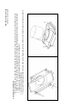
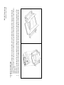
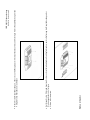
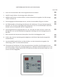
1
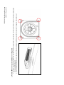
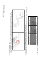
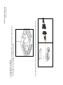
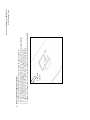
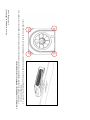
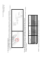
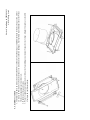
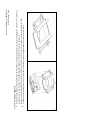
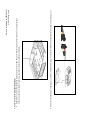
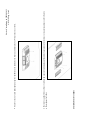
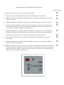
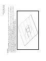
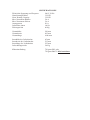
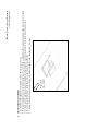
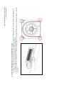
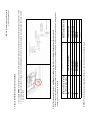
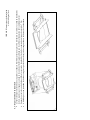
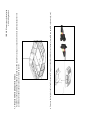
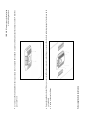
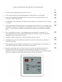
IBIS ROOFTOP AIRCONDITIONER OWNER’S MANUAL Pantone Cool Grey 9U Pantone 301 U Pantone DS196 - 4 U (Alternative) • • • • • Installation Instructions Commissioning of IBIS after installation Possible faults and remedy Specifications Warranty Conditions • • • • • Notice d’installation Mise en service d’IBIS après l’installation Défauts éventuels et solutions Spécifications Conditions de garantie • • • • • Einbauanleitung Inbetriebnahme des IBIS nach dem Einbau Mögliche Probleme und ihre Behebung Spezifikationen Garantiebedingungen • • • • • Instrucciones de Instalación Puesta en Marcha del IBIS después de su instalación Posibles fallos y soluciones Especificaciones Condiciones de la Garantía WARRANTY OF REFRIGERATED AIRCONDITIONING Warranty within Australia We undertake by this warranty to rectify, free of charge, at our nearest authorised service agent, any fault due to faulty workmanship or replacement of any faulty components within 12 months from the date of the first retail purchase thereof. This undertaking is conditional upon the appliance being installed and operated in accordance with our instructions, and does not apply to consumable components such as filters, or to adjustments necessary due to misuse of airconditioner. Normal user maintenance, setting of controls and transit damage are also excluded. No other person, firm or corporation is authorised by us to offer or give on our behalf any other or greater warranty than that given by us under this warranty. The benefits conferred by this warranty are in favour of the original retail purchaser and any other person deriving title to the goods through or under such person and are intended to be separate from the additional to all other rights and remedies which they may have in law in respect of the goods. 1. 2. 3. In the event that warranty service is required, the purchaser must contact Aircommand Australia for service approval. Contact information: phone 08 8445 2877, fax 08 8243 0628, or email [email protected] Warranty repairs will only to be carried out by the manufacturer’s authorised service repairer. It is the purchaser’s responsibility to deliver unit to the manufacturer’s nearest authorised Service Centre. The manufacturer will not bear any costs involved in Service Agent’s travelling expenses or delivery charges. Warranty outside Australia 1. 2. Aircommand products are covered by 12 months warranty from date of first retail purchase. For warranty enquiries outside Australia, please contact your national supplier . * The warranty card must be completed and returned to the manufacturer for registration, or to the distributor in country of purchase. Online warranty registration is available at www.aircommand.com.au/registration.html GARANTIE DE CLIMATISATION RÉFRIGÉRÉE Garantie pour l’Australie Nous nous engageons par cette garantie à faire rectifier gratuitement par notre agent de service tout défaut résultant d’un défaut de fabrication ou de remplacer tout composant défectueux dans les 12 mois suivant la date du premier achat de l’appareil au détail. Cet engagement est conditionnel à l’installation et à l’exploitation de l’appareil conformément à nos instructions, et ne s’applique pas aux composants consommables tels que les filtres, ou à un réglage attribuable à la mauvaise utilisation du climatiseur. L’entretien, les réglages des commandes et les dommages en transit sont également exclus. Aucune autre personne, firme ou entreprise n’est autorisée par nous à offrir ou à donner en notre nom toute autre garantie ou une garantie supérieure à celle donnée par nous en vertu de cette garantie. Les avantages conférés par cette garantie reviennent à l’acquéreur au détail original ou à toute autre personne qui deviendra propriétaire de l’appareil par le biais de cette personne ou avec son autorisation et sont censés être supplémentaires à tous les autres droits et recours dont il pourra disposer légalement en ce qui concerne l’appareil. 1. 2. 3. Au cas où un service de garantie serait nécessaire, l’acquéreur doit contacter Aircommand Australia pour obtenir une autorisation de service. Cordonnées: téléphone 08 8445 2877, fax 08 8243 0628, ou email [email protected] Les réparations sous garantie seront effectuées exclusivement par le réparateur autorisé du fabricant. La responsabilité incombe à l’acquéreur de livrer l’appareil au Centre de service autorisé le plus proche du fabricant. Le fabricant ne subira pas les frais de déplacement ou de livraison de l’agent de service. Garantie en dehors de l’Australie 1. 2. Les produits Aircommand sont couverts par une garantie de 12 mois à compter de la date du premier achat au détail. Pour toute demande de renseignements en dehors de l’Australie, veuillez contacter votre fournisseur national. * La carte de garantie doit être remplie et renvoyée au fabricant pour être enregistrée, ou au distributeur dans le pays de l’achat. Un enregistrement de garantie en ligne est disponible sur www.aircommand.com.au/registration.html GARANTIE FÜR KLIMAGERÄT MIT KÜHLFUNKTION Garantie innerhalb Australiens Wir verpflichten uns mit dieser Garantie, innerhalb von 12 Monaten ab Datum des ersten Einzelhandelskaufs, über unseren nächsten Vertragshändler jeden durch fehlerhafte Verarbeitung entstandenen Defekt kostenlos zu beheben oder alle defekten Teile kostenlos auszutauschen. Diese Verpflichtung gilt unter dem Vorbehalt, dass das Gerät im Einklang mit unseren Anleitungen installiert und betrieben wird, und gilt nicht für Verschleißteile wie z.B. Filter oder für Korrekturarbeiten, die durch den Missbrauch des Klimageräts bedingt sind. Normale Wartung durch den Benutzer, die Einstellung der Bedienelemente und Transportschäden sind ebenfalls ausgeschlossen. Wir haben keine anderen Personen, Firmen oder Unternehmen bevollmächtigt, in unserem Namen irgendeine andere oder weiter reichende Garantie anzubieten oder zu geben als die von uns im Rahmen dieser Garantie erteilte. Die mittels dieser Garantie gewährten Leistungen gelten zu Gunsten des ursprünglichen Einzelhandelskäufers oder jeder anderen Person, die ihren Anspruch auf die Waren durch oder von dieser Person ableitet, und sind dazu gedacht, getrennt von allen zusätzlichen Rechten und Behelfen zu gelten, die ihnen kraft Gesetzes hinsichtlich dieser Waren zustehen.. 1. 2. 3. Für den Fall, dass eine Garantieleistung erforderlich wird, muss sich der Käufer mit Aircommand Australia zur Genehmigung der Leistung in Verbindung setzen. Kontaktinfo: Tel. 08 8445 2877, Fax: 08 8243 0628 oder E-Mail: [email protected] Unter die Garantie fallende Reparaturen werden nur durch den Vertragsreparaturdienst des Herstellers ausgeführt. Die Lieferung des Geräts an das nächstliegende Service Centre des Herstellers ist Aufgabe des Käufers. Der Hersteller deckt keine der durch die Anfahrtskosten des Vertragsdienstes oder Lieferkosten entstandenen Ausgaben. Garantie außerhalb Australiens 1. 2. Für die Produkte von Aircommand gilt eine 12-monatige Garantie ab Datum des ersten Einzelhandelskaufs. Für Garantieanfragen außerhalb Australiens wenden Sie sich bitte an Ihren inländischen Händler. * Die Garantiekarte ist auszufüllen und dem Hersteller, bzw. dem Vertriebshändler im Einkaufsland, zur Registrierung zuzuschicken. Die Garantie kann online unter der folgenden Adresse registriert werden: www.aircommand.com.au/registration.html GARANTÍA DEL ACONDICIONADOR DE AIRE REFRIGERADO Garantía en Australia Nos comprometemos por medio de esta garantía a rectificar, sin cargo, en nuestra agencia de servicio autorizado, cualquier fallo causado por un componente defectuoso dentro de los 12 meses contados a partir de la primera fecha de compra. Este compromiso es condicional a que el aparato haya sido instalado y operado de acuerdo con nuestras instrucciones y no cubre componentes de consumo tales como filtros, o cualquier ajuste necesario debido al uso incorrecto del acondicionador de aire. Se excluyen también las tareas de mantenimiento normales, el ajuste de los controles y cualquier daño ocurrido durante su transporte. Ninguna otra persona, firma o corporación está autorizada a ofrecer o dar en nuestro nombre una garantía más extensa o diferente a la otorgada por esta garantía. Los beneficios conferidos por esta garantía son a favor del comprador original y cualquier otra persona que tenga derecho al título de la mercadería a través o bajo dicha persona y está separada de otros derechos adicionales o soluciones a las que puedan tener derecho, según la ley, respecto a las mercaderías. 1. 2. 3.. En el caso que se necesite hacer uso del servicio de garantía, el comprador debe ponerse en contacto con Aircommand Australia para la aprobación del servicio. Información de contacto: Teléfono: 08 8445 2877, Fax 08 8243 0628 o Email [email protected] Las reparaciones cubiertas por la garantía deberán ser llevadas a cabo por el servicio de reparaciones autorizado por el fabricante. La entrega de la unidad al Centro de Servicio más cercano autorizado por el fabricante es responsabilidad del comprador El fabricante no se hará responsable de ninguno de los costes involucrados por gastos de viaje o cargos de entrega por parte del agente proveedor del servicio Garantía fuera de Australia 1. 2. Los productos de Aircommand están cubiertos por 12 meses de garantía a partir de la primera fecha de compra. Por cualquier información respecto a la garantía fuera de Australia, sírvase ponerse en contacto con su proveedor nacional. * Esta tarjeta de garantía debe ser completada y enviada al fabricante para su debida registración o alternativamente al distribuidor en el país de compra. La registración de la garantía puede hacerse también online en: www.aircommand.com.au/registration.html CUSTOMER’S COPY Purchaser’s Name ............................................................................................................................................................................................................................. Address ................................................................................................................................................................................................................................................ ............................................................. P/Code .......................................... Phone ............................................ Email ............................................................ Purchase Date ........................................................................................... Installed on ............................................................................................................. Model ........................................................................................................... Serial Number ........................................................................................................ Purchased From ................................................................................................................................................................................................................................ Address ................................................................................................................................................................................................................................................ ............................................................. P/Code .......................................... Phone ............................................ Email ............................................................ COPIE DU CLIENT Nom de l’acquéreur ......................................................................................................................................................................................................................... Adresse ................................................................................................................................................................................................................................................ ............................................................. Code postal ................................. Téléphone .................................... Email ............................................................ Date de l’achat .......................................................................................... Installé le ................................................................................................................. Modèle ........................................................................................................ Numéro de série .................................................................................................... Acheté chez ........................................................................................................................................................................................................................................ Adresse ................................................................................................................................................................................................................................................ ............................................................. Code postal ................................ Téléphone ................................... Email ............................................................ KOPIE FÜR DEN KÄUFER Name des Käufers ............................................................................................................................................................................................................................ Anschrift .............................................................................................................................................................................................................................................. ............................................................. PLZ ................................................. Telefon .......................................... Email ............................................................. Kaufdatum ................................................................................................. Einbaudatum .......................................................................................................... Modell ......................................................................................................... Seriennummer ....................................................................................................... Gekauft bei ......................................................................................................................................................................................................................................... Anschrift .............................................................................................................................................................................................................................................. ............................................................. PLZ ................................................. Telefon ........................................... Email ............................................................ COPIA PARA EL CLIENTE Nombre del Comprador ................................................................................................................................................................................................................ Dirección ............................................................................................................................................................................................................................................. ............................................................. Código Postal ............................. Teléfono ........................................ Email ............................................................ Fecha de compra .................................................................................... Fecha de instalación ............................................................................................ Modelo ........................................................................................................ Número de Serie ................................................................................................... Comprado en ..................................................................................................................................................................................................................................... Dirección ............................................................................................................................................................................................................................................. ............................................................. Código Postal ............................. Teléfono ........................................ Email ............................................................ 14 inch square hole REAR OF UNIT DIRECTION OF TRAVEL CALL AIRCOMMAND FOR ADVICE IF YOUR INSTALLATION DIFFERS SIGNIFICANTLY DISTANCES SHOWN ARE CALCULATED FROM A 14” SQUARE HOLE (356X356MM) THE OUTLINE SHOWS THE MINIMUM CLEARANCE REQUIRED AROUND THE IBIS ROOF UNIT FRONT OF UNIT DIRECTION OF TRAVEL MINIMUM 25MM CLEARANCE FROM SIDE GRILL TO ANY OBSTRUCTION IMPORTANT NOTE: FRONT OF UNIT MUST FACE DIRECTION OF TRAVEL FAILURE TO FOLLOW THIS INSTRUCTION WILL RESULT IN DAMAGE TO CONDENDER FANS MINIMUM 200MM CLEARANCE FROM REAR GRILLE TO ANY VERTICAL FACE MINIMUM 100MM CLEARANCE TO ANY 45 DEGREE FACE REAR OF UNIT HOT AIR IS EJECTED FROM THESE EXHAUSTS CONSIDER HATCH POSITIONS AT THE REAR OF THE UNIT NOTE POSITION OF TWIN CONDENSER EXHAUSTS 1. Consider Installation position Before you begin, mark out the position of the unit considering the following important requirements for positioning unit on rooftop. The air conditioner should be situated as centrally as possible on the van, to give even air distribution within the air-conditioned space. Avoid an installation position where a bulkhead, cupboard or return could interfere with the discharge air flow from the inside plenum. The outside unit needs to conform to the figure below It is important that the unit is never more than 5° from the horizontal and the rear of the unit should never be higher than the front. If your installation is likely to exceed these limits contact Aircommand for specialist advice Installation Instructions - Ibis Rooftop Reverse Cycle Air conditioner IBIS Mk II Installation Instruction 6/8/2010 Page 1 of 9 1. Roof strength • The roof members MUST be strong enough to support the weight of the airconditioner (up to 50kg) without any roof deflection that will cause ‘pooling’ of water around the unit. • If in any doubt as to the strength of the roof then consider the use of an external ‘H” frame. Contact Aircommand for further details. • The square hole on the roof (356x356mm, 14”x14”) MUST be boxed up with minimum 20mm square timber to provide a structure that is strong enough to withstand the compression of the installation bolts. • Longitudinals MUST be fixed securely to the transverse roof members to transfer load IBIS Mk II Installation Instruction 6/8/2010 Page 2 of 9 Front of Caravan 2. Install self adhesive gasket 1. The roof area must be clean and dry and free from grease or oil 2. Remove paper backing from the roof sealing gasket and position over square hole as shown 3. Gasket must be applied with the self adhesive side down. Note orientation of gasket to direction of travel. 4. Press gasket down firmly to ensure good adhesion 5. Run a bead of silicone between the roof and the gasket around the entire perimeter of the gasket IBIS Mk II Installation Instruction 6/8/2010 Page 3 of 9 2. Position IBIS roof top air conditioner over the gasket 1. Position the unit on the gasket so that the corners of square hole in the caravan roof line up with the corners of the square hole under the air conditioning unit. 2. Four M8 mounting holes on the chassis of the air conditioner will line up with the corners of the square hole in the roof IBIS Mk II Installation Instruction 6/8/2010 Page 4 of 9 Blue A Brown 15 Amp power inlet 15 Amp 2 pole RCD Minimum contact gap of 3mm in OFF position cable min. area 1.5 squ. mm min 7 strand Rigid Roof thickness (mm) Duct length required Hold down bolt length (mm) required (mm) Include ‘H’ frame if used 125 150 (as supplied) As supplied 100 125 (cut 25) As supplied 80 105 (cut 45) As supplied 60 85 (cut 65) Cut 50 40 65 (cut 85) Cut 70 25 (absolute minimum) 50 (cut 100) Cut 85 NOTE - If the Duct length needs to be adjusted then cut excess from the un-notched end 4. Assess roof thickness and modify flexible duct and hold-down bolts if required Measure the thickness of the caravan roof and use following table to check if adjustment to hold down bolts and duct length is required: Y&G N connection block at airconditioner 3. Connect Electrical supply to unit 1. This unit MUST be installed in accordance with National Wiring regulations and in particular AS3001 - 2008 2. Refer to wiring diagram below. Connect electrical supply to terminal strip. Note position of active, line and ground IBIS Mk II Installation Instruction 6/8/2010 Page 5 of 9 5. Assemble duct 1. Thread a hold-down bar onto the M8 bolt and push the bolt almost all the way into the hole at each corner. Leave a 10mm gap between the hold-down bar and the recess in the plastic brace. This will allow easier engagement with the 4 corresponding threaded holes in the roof top unit 2. Repeat for all four corners 3. Add black plastic duct to the top of the assembly with the notch upwards. Align the notch with the inside fans power cable IBIS Mk II Installation Instruction 6/8/2010 Page 6 of 9 6. Attach duct to unit • Raise duct assembly and engage the flexible black plastic duct on the outside diameter of the outlet from the roof top unit. Ensure that key hole cut out in the flexible duct aligns with the inside fan's power cable • Engage and tighten the four M8 bolts with the threaded insets in the roof top unit. Recommended tightening torque is Nm • As the bolts are tightened ensure that the hold-down bars engage with their recesses in the brace IBIS Mk II Installation Instruction 6/8/2010 Page 7 of 9 • Connect key pad cable to control cable. Note that wire colour should correspond (yellow to yellow, red to red etc) 7. Attach Main Cover of Plenum • Suspend the main cover from the duct by attaching the blue cord to the lug on the inside of main cover. This will allow you to use both hands to connect the control cable. IBIS Mk II Installation Instruction 6/8/2010 Page 8 of 9 Remove the filter units and use the six counter sunk self tapping screws to secure the main covers edge to the caravan ceiling Replace filters • • Installation is complete Raise the main cover up so that it engages with the duct assembly and secure the main cover to the duct with 4 screws provided • IBIS Mk II Installation Instruction 6/8/2010 Page 9 of 9 COMMISSIONING OF THE IBIS AFTER INSTALLATION COMMISSIONING OF THE IBIS AFTER INSTALLATION Check OK 1. TurnTurn on power at the circuit breaker or ECB. on power at the circuit breaker or ECB. 2. PresstheON/OFFbutton.Thedisplayshouldilluminate. Press the ON/OFF button . The display should illuminate 3. PressMODEbuttonandcycletoenterthecoolingmode.The“COOL”LEDwillilluminate Press MODE button and cycle to enter the cooling mode. The “COOL” LED will illuminate 4. Thedisplaywillbereadingtheroomtemperatureandtheinsidefanwillstart. The display will be reading the room temperature and the inside fan will start. 5. UsetheTEMPbuttonstoadjustthesetpointtoatleast3⁰Cbelowtheroomtemperature Use the TEMP buttons to adjust the set point to at least 3C below the room temperature. ie.Displaysaysroomtemperatureis25⁰C,thenusetheup/downbuttonstosetsay22⁰C. Ie. Display says room temperature is 25C, then use the up/down buttons to set say 22C. 6. Thedisplaywillflash“22”forafewsecondsandrevertto25⁰C.Theairconditionerisnow settocomeontoCooling.Theremaybea3minutedelayhowever. The display will flash “22” for a few seconds and revert to 25C. The airconditioner is now set to come onto Cooling. There may be a 3 minute delay however. 7. Whencompressorstarts,checkthatcoolairisbeingdischarged. When compressor starts, check that cool air is being discharged. 8. CheckthatallthreefanspeedscanbeselectedviatheFANbutton. Check that all three fan speeds can be selected via the FAN button. 9. NowpressMODEbuttonandcyclethroughtoentertheheatmode.The“HEAT”LEDwill beconstantlyilluminated. Now press MODE button and cycle through to enter the heat mode. The “HEAT” LED will be constantly illuminated. 10.Setthethermostattoatleast3⁰Cabovetheroomtemperature.Theairconditioneris readytoheat.Afterthe3minutedelayperiod,thecompressorwillstartandtheinside Set the thermostat to at least 3C above the room temperature. The airconditioner is ready fanwillstop.Afterashortperiodthefanwillstartautomaticallyandwarmairwillbe to heat. After the 3 minute delay period, the compressor will start and the inside fan will discharged. stop. After a short period the fan will start automatically and warm air will be discharged. SPECIFICATIONS Electrical rating Nom. Cooling capacity Nom. Heating Capacity Max rated current cooling Max rated current heating L/R Amps Inside air delivery Installed weight 240 V 50 Hz 3.2 KW 3.2 KW 5.4 Amps 5.6 Amps 20 Amps 140 l/s 49 Kg Overall height Overall width Overall length 220 mm 825 mm 1040 mm Inside plenum height Inside plenum width Inside plenum length Plenum weight 65 mm 535 mm 555 mm 2.4 Kg Refrigerant Charge 720 grms R22 or 720 grms R407C if marked POSSIBLE FAULTS AND REMEDY Control Pad will not illuminate when ON/OFF button is depressed • Check power supply to van OK • Check circuit breaker is on • Control cable may be unplugged between outside unit and inside facia. Unit does not cool • Ensure mode button has the green cool LED Illuminated constantly • Thermostat set point must be below room temperature NB: The compressor has a 3 minute delay to start and so may not start immediately. Unit does not heat. • Ensure mode button has the red LED illuminated constantly. • Thermostat set point must be above room temperature • Beware compressor may have a delayed start • In very cold conditions, unit will take more time to start producing warm air. Insufficient cooling capacity • Ensure return air filters are clean • Operate the unit on high fan speed to obtain maximum capacity. • Ensure all doors and windows and skylights are closed, and curtains and awnings used to reduce heat load. An error code is displayed on control panel. May be an E1 to E5 • Refer contact details on back page ARRIERE DE L’APPAREIL DIRECTION DE LA MARCHE TROU CARRÉ DE 14 POUCES (35 CM) ARRIERE DE L’APPAREIL DIRECTION DU DEPLACEMENT DIRECTION DU DEPLACEMENT DE NT IL AVA PARE L’AP CONTACTER AIRCOMMAND SI VOTRE INSTALLATION DIFFERE SIGNIFICATIVEMENT DE CELLE-CI LES DISTANCES INDIQUÉES SONT CALCULEES SUR LA BASE D’UN TROU CARRÉ DE 356MM X 356MM CE PLAN MONTRE L’ESPACE MIN. REQUIS AUTOUR DE L’APPAREIL DE TOIT IBIS ESPACE MIN.DE 25MM ENTRE LA GRILLE LATERALE ET UNE SURFACE VERTICALE IMPORTANT: L’AVANT DE L’APPAREIL DOIT ETRE DANS LE SENS DE LA MARCHE. SINON, LES VENTILATEURS DU CONDENSEUR RISQUENT D’ETRE ENDOMMAGÉS ESPACE MIN.DE 200MM ENTRE LA GRILLE ARRIERE ET UNE SURFACE VERTICALE ESPACE MIN.DE 100MM ENTRE LA GRILLE LATERALE ET UNE SURFACE À 45 DEGRÉS ARRIERE DE L’APPAREIL L’AIR CHAUD EST EXPULSÉ DE CES SORTIES CONSIDERE LES POSITIONS DE LA TRAPPE A L’ARRIERE DE L’APPAREIL NOTER LA POSITION DES DEUX SORTIES DE CONDENSEUR 1. Considérer l’emplacement de l’installation Avant de commencer, marquer la position de l’appareil en tenant compte des exigences importantes suivantes pour le positionner sur le toit. Le climatiseur doit être situé à un emplacement aussi central que possible sur le véhicule pour assurer une distribution d’air uniforme dans l’espace climatisé. Eviter de l’installer là où une cloison, un placard ou un retour pourrait obstruer le débit d’air en provenance du plenum interne. L’unité extérieure doit est conforme à la figure ci-dessous Il est important que l’unité ne soit jamais à plus de 5° de l’horizontale et que l’arrière de l’unité ne soit jamais plus haut que l’avant. Si votre installation risque de dépasser ces limites, contactez Aircommand pour obtenir des conseils spécialisés. Notice d’installation – Climatiseur à cycle réversible de toit Ibis Notice d’installation de l’IBIS Mk II 6/8/2010 Page 1 sur 9 1. Solidité du toit • Les membres du toit DOIVENT être assez solides pour soutenir le poids du climatiseur (jusqu'à 50 kg) sans fléchissement du toit, ce qui causerait l’accumulation d’eau autour de l’appareil. • En cas de doute quant à la solidité du toit, envisager l’utilisation d’un cadre externe en H. Contacter Aircommand pour plus de détails. • The trou carré prévu sur le toit (356x356 mm, 14" x 14") DOIVENT être encadré au moyen d’un cadre en bois de 20mm pour fournir une structure suffisamment solide pour résister à la compression des boulons d’installation. • Des membres longitudinaux DOIVENT être fixés solidement aux membres transversaux du toit pour transférer la charge. Notice d’installation de l’IBIS Mk II 6/8/2010 Page 2 sur 9 Avant de la caravane 2. Poser le joint d’étanchéité autocollant 1. La surface du toit doit être propre et sèche et exempte de graisse ou d’huile. 2. Enlever le fond papier du joint d’étanchéité de toit et le placer sur le trou carré comme indiqué 3. Le joint d’étanchéité doit être appliqué avec l’autocollant orienté vers le bas. 4. Appuyer fermement sur le joint d’étanchéité pour obtenir une bonne adhésion. 5. Appliquer de la silicone entre le toit et le joint d’étanchéité autour du périmètre du joint d’étanchéité. Notice d’installation de l’IBIS Mk II 6/8/2010 Page 3 sur 9 2. Positionner le climatiseur de toit IBIS sur le joint d’étanchéité 1. Positionner l’unité sur le joint d’étanchéité de sorte que les coins du trou carré du toit de la caravane s’alignent avec les coins du trou carré sous le climatiseur. 2. Les quatre trous de montage M8 situés sur le châssis du climatiseur s’aligneront avec les coins du trou carré dans le toit. Notice d’installation de l’IBIS Mk II 6/8/2010 Page 4 sur 9 Bleu A Marron Prise électrique de 15 Amp RCD à 2 pôles 15 A Espace de contact min. de 3 mm en position arrêt Câble rigide – surface min. 1,5 mm2 7 fils min Longueur de boulons d’ablocage requise (mm) Tel que fourni Tel que fourni Tel que fourni Couper 50 Couper 70 Couper 85 Longueur de conduit requise (mm) 150 (tel que fourni) 125 (couper 25) 105 (couper 45) 85 (couper 65) 65 (couper 85) 50 (couper 100) NOTA: Si la longueur du conduit doit être ajustée, couper l’excès de l’extrémité sans encoche. Epaisseur du toit (mm) Inclure le cadre « en H » si utilisé 125 100 80 60 40 25 (minimum absolu) 4. Evaluer l’épaisseur du toit et modifier le conduit flexible et les boulons d’ablocage si nécessaire Mesurer l’épaisseur du toit de la caravane et utiliser le tableau suivant pour vérifier si un ajustement du conduit flexible et des boulons d’ablocage est nécessaire: J&V N Bloc de connexion du climatiseur 3. Connecter l’alimentation à l’appareil 1. Cet appareil DOIT être installé conformément aux règlements de câblage nationaux, en particulier AS3001-2008. 2. Consulter le schéma de câblage ci-dessous. Connecter l’alimentation électrique à la plaque à bornes. Noter la position active, ligne et terre. Notice d’installation de l’IBIS Mk II 6/8/2010 Page 5 sur 9 5. Assembler le conduit 1. Introduire une barre de retenue dans le boulon M8 et enfoncer le boulon presque complètement dans le trou de chaque coin. Laisser un espace de 10mm entre la barre de retenue et le retrait dans le renfort en plastique. Ceci facilitera le positionnement sur les 4 trous filetés correspondants sur l’unité de toit. 2. Répéter pour les quatre coins. 3. Placer le conduit en plastique noir sur le haut de l’assemblage en orientant l’encoche vers le haut. Aligner l’encoche avec le câble électrique du ventilateur interne. Notice d’installation de l’IBIS Mk II 6/8/2010 Page 6 sur 9 6. Fixer le conduit à l’appareil • Soulever l’ensemble du conduit en plastique noir flexible et l’accoupler au diamètre externe de la décharge de l’unité de toit. Veiller à ce que la découpe en trou de serrure du conduit flexible s’aligne avec le câble électrique du ventilateur. • Engager les quatre boulons M8 dans les inserts filetés de l’unité de toit et les serrer. Le couple de serrage recommandé est 7 Nm. • À mesure que les boulons sont serrés, vérifier que les barres de retenue s’engagent dans leurs retraits sur le renfort. Notice d’installation de l’IBIS Mk II 6/8/2010 Page 7 sur 9 • Connecter le câble du pavé numérique au câble de commande. Noter que la couleur des fils doit correspondre (jaune à jaune, rouge à rouge, etc.) 7. Fixer le couvercle principal du plenum • Suspendre le couvercle principal au conduit en fixant le cordon bleu à l’oreille de fixation à l’intérieur du couvercle principal. Cela vous permettra d’utiliser vos deux mains pour connecter le câble de commande. Notice d’installation de l’IBIS Mk II 6/8/2010 Page 8 sur 9 Retirer les unités filtres et fixer le rebord du couvercle principal au plafond de la caravane à l’aide des six vis autotaraudeuses à tête fraisée. Remplacer les filtres • • L’installation est terminée Soulever le couvercle principal pour qu’il s’emboite sur le conduit et le fixer au conduit avec les 4 vis prévues à cet effet. • Notice d’installation de l’IBIS Mk II 6/8/2010 Page 9 sur 9 MISE EN SERVICE DE L’IBIS APRES L’INSTALLATION COMMISSIONING OF THE IBIS AFTER INSTALLATION VérificationOK 1. Mettrel’appareilsoustensionaucoupe-circuitouECB. Turn on power at the circuit breaker or ECB. 2. AppuyersurleboutonON/OFF(Marche/Arrêt).L’affichagedevraits’illuminer. Press the ON/OFF button . The display should illuminate 3. AppuyersurleboutonMODEetdéfilerpourentrerenmodederefroidissement.LeLED “COOL”s’illumine. Press MODE button and cycle to enter the cooling mode. The “COOL” LED will illuminate 4. L’affichageindiquelatempératureambianteetleventilateurinternesemetenmarche. The display will be reading the room temperature and the inside fan will start. 5. UtiliserlesboutonsTEMPpourréglerlepointdeconsigneàaumoins3°Cau-dessousde Use the TEMP buttons to adjust the set point to at least 3C below the room temperature. latempératureambiante;parex.sil’affichageindiquequelatempératureambianteest 25°C,utiliserlesboutonshaut/baspourrégler22°C. Ie. Display says room temperature is 25C, then use the up/down buttons to set say 22C. 6. L’affichageclignote“22”pendantquelquessecondesetseremetsur25°C.Leclimatiseur The display will flash “22” for a few seconds and revert to 25C. The airconditioner is now set estdésormaisréglésurlerefroidissement.Unretardde3minutesesttoutefoispossible. to come onto Cooling. There may be a 3 minute delay however. 7. Quandlecompresseursemetenmarche,vérifierquel’airfroidestexpulsé. When compressor starts, check that cool air is being discharged. 8. Vérifierquelestroisvitessesdeventilateurpeuventêtresélectionnéesaumoyendu Check that all three fan speeds can be selected via the FAN button. bouton FAN. Now press MODE button and cycle through to enter the heat mode. The “HEAT” LED will be 9. AppuyermaintenantsurleboutonMODEetdéfilerpourentrerenmodedechauffage.Le voyantDEL“HEAT”resteallumé. constantly illuminated. 10. Réglerlethermostatsuraumoins3°Cau-dessusdelatempératureambiante.Leclimatiseur Set the thermostat to at least 3C above the room temperature. The airconditioner is ready estdésormaisprêtàchauffer.Auboutde3minutes,lecompresseursemetenmarcheetle to heat. After the 3 minute delay period, the compressor will start and the inside fan will ventilateurinternes’arrête.Auboutd’unbrefmoment,leventilateursemetautomatique stop. After a short period the fan will start automatically and warm air will be discharged. mentenmarcheetexpulsedel’airchaud. SPECIFICATIONS Caractéristiques assignées Capacité de refroidissement nom. Capacité de chauffage nom. Courant assigné max Courant assigné max Ampères G/D Soufflage interne Poids installé 240 V 50 Hz 3.2 KW 3.2 KW 5.4 Amps 5.6 Amps 20 A 140 l/s 49 Kg Hauteur hors tout Largeur hors tout Longueur hors tout 220 mm 825 mm 1040 mm Hauteur du plenum interne Largeur du plenum interne Longueur du plenum interne Poids du plenum 65 mm 535 mm 555 mm 2.4 Kg Charge de réfrigérant 720 g R22 ou 720 g R407C si marqué DÉFAUTS ÉVENTUELS ET SOLUTIONS Le boîtier de commande ne s’illumine pas quand le bouton ON/OFF est enfoncé • Vérifier l’alimentation de la caravane • Vérifier que le coupe-circuit est sous tension • Il est possible que le câble de commande reliant l’unité extérieure au panneau intérieur soit débranché L’appareil de rafraichit pas • Vérifier que le voyant DEL de refroidissement vert du bouton de mode reste illuminé • Le point de consigne du thermostat doit être au-dessous de la température ambiante NB : Le compresseur a un retard de 3 minutes, par conséquent il risque de ne pas démarrer immédiatement L’appareil de réchauffe pas • Vérifier que le voyant DEL de chauffage rouge du bouton de mode reste illuminé • Le point de consigne du thermostat doit être au-dessus de la température ambiante • Noter que le démarrage du compresseur peut être retardé • Quand il fait très froid, l’appareil prend davantage de temps pour produire de l’air chaud Capacité de refroidissement insuffisante • Vérifier que les filtres d’air sont propres • Régler l’appareil sur une vitesse de ventilateur élevée pour obtenir une capacité maximale. • S’assurer que toutes les portes, les fenêtres et le lanterneau sont fermés, et utiliser des rideaux et des auvents pour réduire la charge de chaleur Un code d'erreur est affiché sur le panneau de commande (E1 à E5) • Se référer aux coordonnées sur la dernière page RÜCKSEITE DES GERÄTS FAHRTRICHTUNG Quadratischer Ausschnitt 356 x 356 mm ERSUCHEN SIE AIRCOMMAND UM BERATUNG, FALLS IHR EINBAU SICH BETRÄCHTLICH VON DIESEM UNTERSCHEIDET. DIE ENTFERNUNGEN SIND VOM QUADRATISCHEN AUSSCHNITT (356 X 356 MM) GERECHNET. DIESER AUFRISS ZEIGT DEN BENÖTIGTEN MINDESTFREIRAUM UM DAS IBIS DACHGERÄT. S DE ITE RSE S DE ERÄT R VO G FAHRTRICHTUNG MINDESTENS 25 MM FREIRAUM VON DER SEITE DES GRILLS BIS ZU JEDEM HINDERNIS. WICHTIGER HINWEIS: DIE VORDERSEITE DES GERÄTS MUSS IN FAHRTRICHTUNG WEISEN. NICHTBEFOLGEN DIESER ANWEISUNG FÜHRT ZUR BESCHÄDIGUNG DER KONDENSATORLÜFTER. MINDESTENS 200 MM FREIRAUM ZWISCHEN DEM RÜCKSEITIGEN GRILL UND JEDER SENKRECHTEN FLÄCHE. MINDESTENS 100 MM FREIRAUM BIS ZU JEDER FLÄCHE MIT EINER NEIGUNG VON 45 GRAD. RÜCKSEITE DES GERÄTS AUS DIESEN AUSGÄNGEN TRITT HEISSLUFT AUS. POSITION VON LUKEN AN DER RÜCKSEITE DES GERÄTS IN BETRACHT ZIEHEN. POSITION DER DOPPELTEN KONDENSATORAUSGÄNGE BEACHTEN. 1. Einbauposition erwägen Bestimmen Sie als erstes die Position des Geräts, wobei Sie die folgenden wichtigen Anforderungen in Hinsicht auf die Platzierung des Geräts auf dem Dach in Erwägung ziehen: Das Klimagerät sollte so zentral wie möglich auf dem Wohnmobil bzw. Wohnwagen angebracht werden, um eine gleichmäßige Luftverteilung innerhalb des klimatisierten Raumes zu gewährleisten. Vermeiden Sie den Einbau an einer Stelle, wo ein Schott, ein Schrank oder eine Trennwand den Abfluss des Luftstroms aus dem Innenluftschacht behindern könnte. Die Anbringung des außenseitigen Geräts muss der folgenden Abbildung entsprechen. Es ist wichtig, dass das Gerät nie mehr als 5° aus der Waage ist; und die Rückseite des Geräts sollte nie höher stehen als die Vorderseite. Falls Ihr Einbau diese Maße vermutlich überschreiten sollte, wenden Sie sich bitte für eine spezielle Beratung an Aircommand. Einbauanleitung - Ibis Dachklimagerät mit Heiz- und Kühlfunktion IBIS Mk II Einbauanleitung 8.6.2010 Seite 1 von 9 1. Dachstärke • Die Dachträger MÜSSEN stark genug sein, um das Gewicht des Klimageräts (bis zu 50 kg) zu tragen, ohne dass sich das Dach verbiegt, da dies Wasserlachen im Umfeld des Geräts verursachen würde. • Sollten Sie irgendwelche Zweifel an der Tragfähigkeit des Daches hegen, erwägen Sie die Anwendung eines externen H-Rahmens. Bitte wenden Sie sich für weitere Einzelheiten an Aircommand. • Der quadratische Dachausschnitt (356 x 356 mm) MUSS mit Holzleisten (20 x 20 mm) verstärkt werden, um eine Konstruktion zu schaffen, die solide genug ist, um die Kompression der Befestigungsbolzen auszuhalten. • Längsträger MÜSSEN zur Lastenübertragung fest mit den Dachquerstreben verbunden sein. IBIS Mk II Einbauanleitung 8.6.2010 Seite 2 von 9 Von der Karawane 2. Selbstklebende Dichtung anbringen 1. Die Dachträger MÜSSEN stark genug sein, um das Gewicht des Klimageräts (bis zu 50 kg) zu tragen, ohne dass sich das Dach verbiegt, da dies Wasserlachen im Umfeld des Geräts verursachen würde. 2. Papierstreifen von der Dachdichtung abziehen und die Dichtung, wie abgebildet, über dem quadratischen Loch platzieren. 3. Dichtung muss mit selbstklebender Seite nach unten aufgebracht werden. Ausrichtung der Dichtung relativ zur Fahrtrichtung beachten. 4. Dichtung fest aufdrücken, um eine gute Haftung zu gewährleisten. 5. Fuge zwischen Dach und Dichtung im gesamten Umriss der Dichtung mit Silikon abspritzen. IBIS Mk II Einbauanleitung 8.6.2010 Seite 3 von 9 2. IBIS Dachklimagerät über der Dichtung platzieren 1. Das Gerät so auf der Dichtung platzieren, dass die Ecken des quadratischen Ausschnitts im Wohnmobildach mit den Ecken des quadratischen Ausschnitts auf der Unterseite des Klimageräts bündig sind. 2. Die vier M8-Befestigungslöcher am Gehäuse des Klimageräts decken sich dann mit den Ecken des quadratischen Ausschnitts im Dach. IBIS Mk II Einbauanleitung 8.6.2010 Seite 4 von 9 P Braun 15 A Leistungsaufnahme RCD 15 A 2-polig Minimumkontaktabstand 3 mm bei AUS-Position Starres Kabel Mindeststärke 1,5 mm2 mindestens 7-adrig erforderliche Luftkanallänge (mm) 150 (wie Liefermaß) 125 (um 25 kürzen) 105 (um 45 kürzen) 85 (um 65 kürzen) 65 (um 85 kürzen) 50 (um 100 kürzen) erforderliche Länge der Befestigungsschrauben (mm) wie Liefermaß wie Liefermaß wie Liefermaß um 50 kürzen um 70 kürzen um 85 kürzen BITTE BEACHTEN - Falls die Länge des Luftkanals geändert werden muss, Überlänge vom ungekerbten Ende abtrennen. Dachdicke (mm) einschl. H-Rahmen falls benutzt 125 100 80 60 40 25 (absolutes Minimum) 4. Bemessung der Dachdicke und Änderung des flexiblen Luftkanals und der Befestigungsschrauben Messen Sie die Dicke des Dachs und benutzen Sie die folgende Tabelle um zu prüfen, ob die Befestigungsschrauben und die Länge des Luftkanals abgeändert werden müssen: Blau grün-gelb N Anschlussblock am Klimagerät 3. Stromversorgung am Gerät anschließen 1. Das Gerät MUSS im Einklang den nationalen Verkabelungsvorschriften und besonders AS3001 - 2008 installiert werden. 2. Siehe Anschlussplan unten. Stromversorgung an die Klemmenleiste anschließen. Position von Positiv, Negativ und Erde beachten. IBIS Mk II Einbauanleitung 8.6.2010 Seite 5 von 9 5. Montage des Luftkanals 1. Befestigungsplatte auf die Schraube M8 aufdrehen und die Schraube fast die gesamte Länge bis in das Eckloch drücken. Einen Abstand von 10 mm zwischen der Befestigungsplatte und der Ausbuchtung der Plastikmanschette belassen; dies erleichtert die Verbindung mit den 4 gegenüberliegenden Schraubenlöchern des Dachgeräts. 2. In allen vier Ecken wiederholen. 3. Schwarzen Plastikkanal mit der Kerbe nach oben auf die Baugruppe aufsetzen. Kerbe auf die Kabel des Innenventilators ausrichten. IBIS Mk II Einbauanleitung 8.6.2010 Seite 6 von 9 6. Kanal am Gerät anbringen • Die Baugruppe mit dem Luftkanal anheben und den flexiblen, schwarzen Plastikkanal am Außenrand des Ausgangs des Dachgeräts ansetzen. Vergewissern Sie sich, dass das in dem flexiblen Luftkanal ausgeschnittene Schlüsselloch auf das Kabel des Innenventilators ausgerichtet ist. • Führen Sie die vier Schrauben M8 in die Gewindelöcher im Dachgerät ein und ziehen sie diese an. Empfohlenes Anzugsmoment ist 7 Nm. • Vergewissern Sie sich, dass die Befestigungsplatten beim Anziehen der Schrauben in die Ausbuchtungen der Manschette eingreifen. IBIS Mk II Einbauanleitung 8.6.2010 Seite 7 von 9 • Verstöpseln Sie das Kabel des Tastenfelds mit dem Steuerkabel. Beachten Sie dabei, dass die Kabelfarben übereinstimmen müssen (Gelb an Gelb, Rot an Rot usw.) 7. Anbringen der Hauptabdeckung des Luftschachts • Hängen Sie die Hauptabdeckung vom Luftkanal ab, indem Sie die blaue Kordel an der Öse auf der Innenseite der Hauptabdeckung befestigen. Dies ermöglicht Ihnen, beide Hände für den Anschluss des Steuerkabels frei zu haben. IBIS Mk II Einbauanleitung 8.6.2010 Seite 8 von 9 Entfernen Sie die Filter und benutzen Sie die sechs selbstschneidenden Senkkopfschrauben, um die Einfassung der Hauptabdeckung an der Wohnwagendecke zu befestigen. Filter wieder einsetzen. • Einbau ist beendet. • Heben Sie die Hauptabdeckung an, sodass sie auf der Baugruppe mit dem Luftkanal aufsitzt, und befestigen Sie die Hauptabdeckung mit den 4 mitgelieferten Schrauben am Luftkanal. • IBIS Mk II Einbauanleitung 8.6.2010 Seite 9 von 9 INBETRIEBNAHME DES IBIS NACH DEM EINBAU COMMISSIONING OF THE IBIS AFTER INSTALLATION Check OK 1. StromamSchutzschalteroderSicherungsautomateneinschalten. 2. ON/OFF-Knopfdrücken.DieAnzeigesollteaufleuchten. Turn on power at the circuit breaker or ECB. 3. MODE-Knopfdrückenunddurchlaufen,umdenKühlmoduseinzugeben.DieLED-Anzeige Press the ON/OFF button . The display should illuminate “COOL“leuchtetauf. Press MODE button and cycle to enter the cooling mode. The “COOL” LED will illuminate 4. DieAnzeigegibtdieRaumtemperaturan,undderInnenventilatorfängtanzulaufen. The display will be reading the room temperature and the inside fan will start. 5. DieTEMP-KnöpfezurEinstellungdesSollwertsaufmindestens3°CunterRaumtemperatur benutzen;d.h.beieinerangezeigtenRaumtemperaturvon25°CdiePfeilknöpferauf/runter Use the TEMP buttons to adjust the set point to at least 3C below the room temperature. drücken,biseineTemperaturvon22°Ceingestelltist. Ie. Display says room temperature is 25C, then use the up/down buttons to set say 22C. 6. DieAnzeigeblinktfüreinigeSekundenauf„22“undstelltsichdannauf25°Czurück.Das KlimagerätistnunaufdenKühlbetriebeingestellt,allerdingsmiteinerVerzögerungvon3 The display will flash “22” for a few seconds and revert to 25C. The airconditioner is now set Minuten. to come onto Cooling. There may be a 3 minute delay however. 7. BeimAnlaufendesKompressorsbitteprüfen,dasskühleLuftabgegebenwird. When compressor starts, check that cool air is being discharged. 8. Prüfen,dassalledreiVentilatorgeschwindigkeitenmithilfedesFAN-Knopfesausgewählt Check that all three fan speeds can be selected via the FAN button. werdenkönnen. Now press MODE button and cycle through to enter the heat mode. The “HEAT” LED will be 9. JetztdenMODE-Knopfdrückenunddurchlaufen,umdenHeizmoduseinzugeben.Die constantly illuminated. LED-Anzeige„HEAT“istdauerhafterleuchtet. 10.Thermostataufmindestens3°CüberRaumtemperatureinstellen.DasKlimagerätistjetzt Set the thermostat to at least 3C above the room temperature. The airconditioner is ready zumHeizenbereit.NacheinerVerzögerungszeitvon3MinutenläuftderKompressoranund to heat. After the 3 minute delay period, the compressor will start and the inside fan will derInnenventilatorstoppt.NachkurzerZeitläuftderVentilatorautomatischwiederan,und stop. After a short period the fan will start automatically and warm air will be discharged. warmeLuftwirdabgegeben. SPEZIFIKATIONEN Elektrische Spannung und Frequenz Nennleistung Kühlen Nom. Heating Capacity Max. Nennstrom Kühlen Max. Nennstrom Heizen Anzugsstrom Luftzufluss innen Einbaugewicht 240 V 50 Hz 3.2 KW 3.2 KW 5.4 A 5.6 A 20 A 140 l/s 49 Kg Gesamthöhe Gesamtbreite Gesamtlänge 220 mm 825 mm 1040 mm Innenhöhe des Luftschachts Innenbreite des Luftschachts Innenlänge des Luftschachts Luftschachtgewicht 65 mm 535 mm 555 mm 2.4 Kg Kältemittelladung 720 grms R22 oder 720 grms R407C falls bezeichnet MÖGLICHE PROBLEME UND IHRE BEHEBUNG Bedienungsgerät leuchtet nicht, wenn ON/OFF-Knopf gedrückt wird. • Prüfen, dass Stromzufuhr zum Wohnmobil bzw. Wohnwagen in Ordnung ist. • Prüfen, dass Schutzschalter eingeschaltet ist. • Steuerkabel zwischen Außengerät und Innenarmatur vielleicht nicht eingesteckt. Gerät kühlt nicht. • Prüfen, ob die grüne LED-Kühlanzeige des MODE-Knopfes dauerhaft euchtet. • Einstellung des Thermostats muss unter Raumtemperatur liegen. NB. Der Kompressor hat vor dem Anlauf eine Verzögerungszeit von 3 Minuten, und läuft vielleicht nicht sofort an. Gerät heizt nicht. • Prüfen, ob die rote LED-Heizanzeige des MODE-Knopfes dauerhaft leuchtet. • Einstellung des Thermostats muss über Raumtemperatur liegen. • Bedenken Sie, dass der Kompressor eine verzögerte Anlaufzeit haben kann. • Bei sehr kalter Witterung braucht das Gerät länger, bis es anfängt, Warmluft zu produzieren. Unzureichende Kühlleistung. • Gewährleisten, dass die Rückluftfilter sauber sind. • Gerät auf höchster Ventilatorgeschwindigkeit laufen lassen, um maximale Leistung zu erzielen. • Gewährleisten, dass alle Türen, Fenster und Oberlichter sowie Gardinen und Markisen geschlossen sind, um Wärmebelastung zu reduzieren. Bedienungsgerät zeigt einen Fehlercode von E1 bis E5 an. • Siehe Kontaktdetails auf der Rückseite. PARTE POSTERIOR DE LA UNIDAD Agujero cuadrado de 14 pulgadas DIRECCIÓN DE VIAJE AVISO IMPORTANTE: EL FRENTE DE LA UNIDAD DEBE ENFRENTAR LA DIRECCIÓN DE VIAJE. EL NO SEGUIR LAS INSTRUCCIONES RESULTARÁ EN DAÑO A LOS VENTILADORES DEL CONDENSADOR E ED NT AD FRE UNID LA SI SU INSTALACIÓN ES SIGNIFICATIVAMENTE DIFERENTE, LLAME A AIRCOMMAND PARA RECIBIR ASESORAMIENTO LAS DISTANCIAS QUE SE MUESTRAN ESTÁN CALCULADAS PARA UN AGUJERO CUADRADO DE 14 PULGADAS (365 X 365 mm) ESTE CONTORNO MUESTRA EL ESPACIO MÍNIMO REQUERIDO ALREDEDOR DE LA UNIDAD DE TECHO IBIS ESPACIO MÍNIMO DE 25 MM DESDE LA PARRILLA LATERAL A CUALQUIER OBSTRUCCIÓN DIRECCIÓN DE VIAJE ESPACIO MÍNIMO DE 200 mm DESDE LA PARRILLA TRASERA A CUALQUIER SUPERFICIE VERTICAL. ESPACIO MÍNIMO DE 100MM A CUALQUIER SUPERFICIE A 45 GRADOS PARTE POSTERIOR DE LA UNIDAD EL AIRE CALIENTE ES DESALOJADO POR ESTOS EXTRACTORES TENGA EN CUENTA LAS POSICIONES EN LA PARTE POSTERIOR DE LA UNIDAD NOTE LA POSICIÓN DE LOS EXTRACTORES GEMELOS DEL CONDENSADOR 1. Considere la posición de la instalación Antes de comenzar, marque la posición de la unidad teniendo en cuenta los siguientes requisitos importantes para determinar la posición de la unidad sobre el techo. El acondicionador de aire debe colocarse lo más centralmente posible sobre la camioneta para que la distribución de aire dentro del espacio refrigerado sea pareja. Evite instalarlo en una posición donde un mamparo, armario o retorno pueda interferir con la l descarga de flujo de aire desde el interior de la cámara de aire.La unidad en el exterior debe colocarse de acuerdo con la ilustración que aparece más abajo. Es importante que la unidad nunca tenga una inclinación mayor de 5°respecto a la horizontal y que la parte trasera de la unidad nunca esté más alta que el frente de la misma. Si existiera la posibilidad de que su instalación excediera estos límites, póngase en contacto con Aircommand para recibir asesoramiento especializado. Instrucciones de Instalación – Acondicionador de Aire IBIS de Ciclo Reversible para Techos IBIS Mk II Instrucciones de Instalación 6/8/2010 Página 1 de 9 1. Resistencia del techo • Los miembros del techo DEBEN ser lo suficientemente resistentes para soportar el peso del acondicionador de aire (hasta 50 kg) para que no se produzca una deflexión del techo lo que causaría que se forme una “laguna” de agua alrededor de la unidad. • Si se tiene duda respecto a la resistencia del techo se debe entonces considerar el uso de un armazón externo en forma de “H”. Por mayores detalles, póngase en contacto con Aircommand. • El agujero cuadrado en el techo (365 x 365 mm) DEBE ser enmarcado con un armazón cuadrado de madera de por lo menos 20 mm para proveer una estructura lo suficientemente fuerte como para resistir la compresión de los pernos de instalación. • Las piezas longitudinales DEBEN fijarse firmemente a las transversales del techo para transferir la carga. IBIS Mk II Instrucciones de Instalación 6/8/2010 Página 2 de 9 Frente de la casa rodante 2. Instalar la junta auto adhesiva 1. La superficie del techo debe estar limpia y seca y libre de grasa o aceite 2. Remueve el papel de atrás de la junta selladora que va en el techo y colóquela sobre el agujero cuadrado según se muestra en la figura 3. La junta se debe colocar con la parte auto-adhesiva hacia abajo. Note la orientación de la junta hacia la dirección de viaje.. 4. Presione la junta firmemente hacia abajo para asegurar una buena adhesión 5. Coloque un borde de silicona entre el techo y la junta alrededor de todo el perímetro de la misma IBIS Mk II Instrucciones de Instalación 6/8/2010 Página 3 de 9 2. Coloque el acondicionador de aire de techo IBIS sobre la junta 1. Coloque la unidad sobre la junta de manera que las esquinas del agujero cuadrado del techo de la casa rodante queden aliñadas con las esquinas del agujero inferior de la unidad del acondicionador de aire. 2. Los cuatro orificios de montaje M8 en el chasis del acondicionador de aire quedarán alineados con las esquinas del agujero cuadrado del techo IBIS Mk II Instrucciones de Instalación 6/8/2010 Página 4 de 9 Azul A Marrón 15 Amp alimentación de entrada 15 Amp 2 polos RCD Mínimo espacio de contacto de 3mm en la posición de apagado (OFF) Cable rígido superficie mínima 1.5 mm2 Mínimo de 7 hilos Longitud necesaria de los bulones de sujeción (mm) Como se proveen Como se proveen Como se proveen Corte 50 Corte 70 Corte 85 Longitud necesaria del conducto (mm) 150 (como se provee) 125 (corte 25) 105 (corte 45) 85 (corte 65) 65 (corte 85) 50 (corte 100) NOTA: Si necesitara ajustar la longitud del conducto, corte el exceso en el extremo sin ranura Espesor del techo (mm) Incluir el marco en forma de “H” si se lo ha usado 125 100 80 60 40 25 (Mínimo absoluto) 4. Evalúe el espesor del techo y modifique los conductos flexibles y los bulones de sujeción si fuera necesario Mida el espesor del techo de la casa rodante y use la tabla que aparece a continuación para verificar si es necesario ajustar la longitud del conducto y de los bulones de sujeción: Y&G N Bloque de conexión al acondicionador de aire 1. Esta unidad DEBE ser instalada de acuerdo con las Regulaciones Nacionales de Cableado y en particular de acuerdo con AS3001 – 2008 2. Ver el diagrama de cableado más abajo. Conecte la alimentación eléctrica a la tira de terminales. Note la posición del activo, la línea y la masa a tierra 3. Conecte la alimentación eléctrica a la unidad IBIS Mk II Instrucciones de Instalación 6/8/2010 Página 5 de 9 5. Armado del conducto 1. Pase una barra de sujeción por el bulón M8 y empuje casi todo el bulón a través del orificio en cada esquina. Deje un espacio de 10 mm entre la barra de sujeción y el hueco en la abrazadera de plástico. Esto permitirá un enganche más fácil con los 4 orificios roscados en la unidad del techo 2. Repita este paso en las cuatro esquinas 3. Agregue el conducto de plástico negro en la parte superior con las ranuras hacia arriba. Aliñe las ranuras con el cable de alimentación de los ventiladores interiores IBIS Mk II Instrucciones de Instalación 6/8/2010 Página 6 de 9 6. Coloque el conducto en la unidad • Levante el conjunto del conducto y enganche el conducto flexible de plástico negro sobre el diámetro exterior de la salida de la unidad de techo. Asegúrese que el agujero cortado en el conducto flexible quede aliñado con el cable de alimentación del ventilador interior • Enganche y ajuste los cuatro bulones M8 en las roscas de la unidad del techo. Se recomienda un torque de ajuste de 7 Nm • A medida que se van ajustando los bulones asegúrese que las barras de sujeción se enganchen en los huecos de la abrazadera IBIS Mk II Instrucciones de Instalación 6/8/2010 Página 7 de 9 • Conecte la clavija del cable al cable de control. Note que el color del cable debe ser el mismo ( Amarillo con amarillo, rojo con rojo, etc.) 7. Coloque la Cubierta principal de la Cámara Suspenda la cubierta principal del conducto pasando el cordón azul por la orejeta que se encuentra dentro de la cubierta principal. Esto le permitirá usar las dos manos para conectar el cable de control. IBIS Mk II Instrucciones de Instalación 6/8/2010 Página 8 de 9 Saque las unidades de los filtros y use seis tornillos auto-terrajantes embutidos para sujetar el borde de la cubierta principal al cielo raso de la casa rodante Vuelva a colocar los filtros • Se ha completado la instalación • Levante la cubierta principal de manera que encaje con el conjunto del conducto y sujete la cubierta principal al conducto con los 4 tornillos que se proveen • IBIS Mk II Instrucciones de Instalación 6/8/2010 Página 9 de 9 PUESTA EN MARCHA DEL IBIS DESPUÉS DE LA INSTALACIÓN OK COMMISSIONING OF THE IBIS AFTER INSTALLATION 1. ConectelaalimentacióndesdeeldisyuntoroECB. 2. PulseelbotónON/OFF(Encendido/Apagado.Sedebeiluminarelvisualizador. Turn on power at the circuit breaker or ECB. 3. PulseelbotónMODE(modalidad)ydecicloparaentrarelciclodeenfriamiento.Se iluminaráelLED“COOL”(Enfriar). Press the ON/OFF button . The display should illuminate 4. Elvisualizadorestaráleyendolatemperaturadelambienteyelventiladorinteriorsepone Press MODE button and cycle to enter the cooling mode. The “COOL” LED will illuminate enmarcha. The display will be reading the room temperature and the inside fan will start. UselosbotonesdeTEMPparaajustarlatemperaturaaporlomenos3°Cpordebajodela temperaturaambiente.Porejemplo:Sielvisualizadordicequelatemperaturaambientees Use the TEMP buttons to adjust the set point to at least 3C below the room temperature. de25°C,uselosbotonesUp/Down(arriba/abajo)paraajustarlatemperaturaadigamos 22°C. Ie. Display says room temperature is 25C, then use the up/down buttons to set say 22C. 6. Enellvisualizadorelnúmero“22”parpadearáporunossegundosyrevertiráa25°C. The display will flash “22” for a few seconds and revert to 25C. The airconditioner is now set Elacondicionadordeaireestáahoraprogramadoparacomenzaraenfriar.Noobstante puededemorarsehastaunos3minutos. to come onto Cooling. There may be a 3 minute delay however. 5. 7. Cuandoarranqueelcompresor,verifiquequeestásaliendoairefrío. When compressor starts, check that cool air is being discharged. 8. Verifiquequelastresvelocidadesdelventiladorsepuedanseleccionarpormediodel Check that all three fan speeds can be selected via the FAN button. botóndelventilador. Now press MODE button and cycle through to enter the heat mode. The “HEAT” LED will be 9. AhorapresioneelbotónMODEhastaqueentreenlamodalidaddelcicloCalefacción.El constantly illuminated. LED“HEAT”(calefacción)quedaráiluminadocontinuamente. Set the thermostat to at least 3C above the room temperature. The airconditioner is ready 10. Ajusteletermostatoaporlomenos3°Cporencimadelatemperaturaambiente.El to heat. After the 3 minute delay period, the compressor will start and the inside fan will acondicionadorestálistoparacalentar.Despuésdeunademorade3minutos,el stop. After a short period the fan will start automatically and warm air will be discharged. compresorarrancaráyelventiladorinteriorsedetendrá.Despuésdeuncortoperiodode tiempoelventiladorarrancaráautomáticamenteyenviaráairecaliente. ESPECIFICACIONES Regimen eléctrico Capacidad Nominal de Enfriamiento Capacidad Nominal de Calentamiento Máxima Corriente de Régimen de Enfriamiento Máxima Corriente de Régimen de Calentamiento L/R Amps Entrega de aire al interior Peso una vez instalado 240 V 50 Hz 3.2 KW 3.2 KW 5.4 Amps 5.6 Amps 20 Amps 140 l/s 49 Kg Altura total Anchura total Longitud total 220 mm 825 mm 1040 mm Altura interior de la cámara Ancho interior de la cámara Inside plenum length Peso de la cámara 65 mm 535 mm 555 mm 2.4 Kg Carga del refrigerante 720 grms R22 ó 720 grms R407C si estuviese indicado POSIBLE FALLOS Y SOLUCIONES El Panel de Control no se ilumina cuando se pulsa el botón ON/OFF (Encendido/Apagado). • Chequear que la fuente de alimentación al van esté OK. • Verifique el disyuntor. • El cable de control puede estar desenchufado entre la unidad exterior y la cara interior. La unidad no enfría • Asegúrese que el botón de modalidad tiene el LED verde encendido constantemente . • El punto de ajuste del termostato debe fijarse por debajo de la temperatura ambiente. • NB: El compresor puede tener una demora de 3 minutos antes de arrancar y por lo tanto puede no arrancar inmediatamente. La unidad no calienta. • Asegúrese que el LED rojo del botón de modalidad esté iluminado constantemente. • El punto de ajuste del termostato debe fijarse por encima de la temperatura ambiente. • El compresor puede demorarse en arrancar. • En condiciones muy frías, la unidad tardará en arrancar y en mandar aire caliente. La capacidad de enfriamiento no es suficiente • Asegúrese que los filtros de retorno estén limpios. • Haga funcionar la unidad con el ventilador en máxima velocidad para obtener el máximo de capacidad. • Asegúrese que todas las puertas y ventanas y los tragaluces estén cerrados y use cortinas y toldos para reducir la carga de calor. El panel de control muestra un error de código. Puede ser E1 a E5. • Lea los detalles de contacto en la última página. Please send to: AIRCOMMAND AUSTRALIA PTY LTD 954 Port Road, Albert Park South Australia 5014 AUSTRALIA Pantone Cool Grey 9U Pantone 301 U Pantone DS196 - 4 U (Alternative) Envoyer à: AIRCOMMAND AUSTRALIA PTY LTD 954 Port Road, Albert Park South Australia 5014 AUSTRALIA Pantone Cool Grey 9U Pantone 301 U Pantone DS196 - 4 U (Alternative) Bitte einschicken an: AIRCOMMAND AUSTRALIA PTY LTD 954 Port Road, Albert Park South Australia 5014 AUSTRALIA Pantone Cool Grey 9U Pantone 301 U Pantone DS196 - 4 U (Alternative) Por favor, sírvase enviar a: AIRCOMMAND AUSTRALIA PTY LTD 954 Port Road, Albert Park South Australia 5014 AUSTRALIA Pantone Cool Grey 9U Pantone 301 U Pantone DS196 - 4 U (Alternative) MANUFACTURER’S COPY Purchaser’s Name ............................................................................................................................................................................................................................. Address ................................................................................................................................................................................................................................................ ............................................................. P/Code .......................................... Phone ............................................ Email ............................................................ Purchase Date ........................................................................................... Installed on ............................................................................................................. Model ........................................................................................................... Serial Number ........................................................................................................ Purchased From ................................................................................................................................................................................................................................ Address ................................................................................................................................................................................................................................................ ............................................................. P/Code .......................................... Phone ............................................ Email ............................................................ COPIE DU FABRICANT Nom de l’acquéreur ......................................................................................................................................................................................................................... Adresse ................................................................................................................................................................................................................................................ ............................................................. Code postal ................................. Téléphone .................................... Email ............................................................ Date de l’achat .......................................................................................... Installé le ................................................................................................................. Modèle ........................................................................................................ Numéro de série .................................................................................................... Acheté chez ........................................................................................................................................................................................................................................ Adresse ................................................................................................................................................................................................................................................ ............................................................. Code postal ................................. Téléphone .................................... Email ............................................................ KOPIE FÜR DEN HERSTELLER Name des Käufers ............................................................................................................................................................................................................................ Anschrift .............................................................................................................................................................................................................................................. ............................................................. PLZ .................................................. Telefon .......................................... Email ............................................................ Kaufdatum .................................................................................................. Einbaudatum ......................................................................................................... Modell .......................................................................................................... Seriennummer ...................................................................................................... Gekauft bei ......................................................................................................................................................................................................................................... Anschrift .............................................................................................................................................................................................................................................. ............................................................. PLZ ................................................. Telefon ............................................ Email ........................................................... COPIA PARA EL FABRICANTE Nombre del Comprador ................................................................................................................................................................................................................ Dirección ............................................................................................................................................................................................................................................. ............................................................. Código Postal ............................. Teléfono ........................................ Email ............................................................ Fecha de compra ..................................................................................... Fecha de instalación ............................................................................................ Modelo ........................................................................................................ Número de Serie ................................................................................................... Comprado en ..................................................................................................................................................................................................................................... Dirección ............................................................................................................................................................................................................................................. ............................................................. Código Postal ............................. Teléfono ........................................ Email ............................................................ Pantone Cool Grey 9U Pantone 301 U AIRCOMMAND AUSTRALIA PTY LTD 954 Port Road, Albert Park South Australia 5014 AUSTRALIA Pantone DS196 - 4 U (Alternative) Tel: (08) 8345 8444 Fax: (08) 8243 0628 AIRCOMMAND EUROPE AIRVA ZI Les Béthunes 10, Avenue du Fief 95310 ST OUEN L AUMONE FRANCE Tel: +33 (0) 134642333 E&OE