1
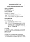
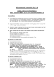
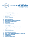
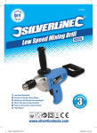
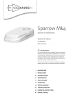
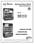
Sandpiper Installation Guide 11th February 2013 – Revision 6 SANDPIPER OWNERS MANUAL - INSTALLATION - COMMISSIONING OF UNIT - MAINTENANCE - SPECIFICATIONS - OPERATING INSTRUCTIONS - CUT OUT TEMPLATES - SPARE PARTS - WIRING DIAGRAM - TROUBLESHOOTING GUIDE Page 1 of 21 Sandpiper Installation Guide 11th February 2013 – Revision 6 Page 2 of 21 WARRANTY OF REFRIGERATED AIRCONDITIONING Warranty within Australia We undertake by this warranty to rectify, free of charge, at our nearest authorised service agent, any fault due to faulty workmanship or replacement of any faulty components within 12 months from the date of the first retail purchase thereof. This undertaking is conditional upon the appliance being installed and operated in accordance with our instructions, and does not apply to consumable components such as filters, or to adjustments necessary due to misuse of airconditioner. Normal user maintenance, setting of controls and transit damage are also excluded. No other person, firm or corporation is authorised by us to offer or give on our behalf any other or greater warranty than that given by us under this warranty. The benefits conferred by this warranty are in favour of the original retail purchaser and any other person deriving title to the goods through or under such person and are intended to be separate from the additional to all other rights and remedies which they may have in law in respect of the goods. Warranty is void if used on commercial applications, including trucks, prime movers, locomotives & machinery. 1. 2. 3. In the event that warranty service is required, the purchaser must contact Aircommand Australia for service approval. Contact information: phone +61 8 8345 8444, fax 08 8243 0628, or email [email protected] Warranty repairs will only to be carried out by the manufacturer’s authorised service repairer. It is the purchaser’s responsibility to deliver unit to the manufacturers nearest authorised Service Centre. The manufacturer will not bear any costs involved in Service Agent’s travelling expenses or delivery charges. Warranty outside Australia 1. Aircommand products are covered by 12 months warranty from date of first retail purchase. 2. For warranty enquiries outside Australia, please contact your national supplier. * The warranty card must be completed and returned to the manufacturer for registration, or to the distributor in country of purchase. Online warranty registration is available at www.aircommand.com.au/registration.html GARANTIE FÜR KLIMAGERÄT MIT KÜHLFUNKTION Garantie innerhalb Australiens Wir verpflichten uns mit dieser Garantie, innerhalb von 12 Monaten ab Datum des ersten Einzelhandelskaufs, über unseren nächsten Vertragshändler jeden durch fehlerhafte Verarbeitung entstandenen Defekt kostenlos zu beheben oder alle defekten Teile kostenlos auszutauschen. Diese Verpflichtung gilt unter dem Vorbehalt, dass das Gerät im Einklang mit unseren Anleitungen installiert und betrieben wird, und gilt nicht für Verschleißteile wie z.B. Filter oder für Korrekturarbeiten, die durch den Missbrauch des Klimageräts bedingt sind. Normale Wartung durch den Benutzer, die Einstellung der Bedienelemente und Transportschäden sind ebenfalls ausgeschlossen. Wir haben keine anderen Personen, Firmen oder Unternehmen bevollmächtigt, in unserem Namen irgendeine andere oder weiter reichende Garantie anzubieten oder zu geben als die von uns im Rahmen dieser Garantie erteilte. Die mittels dieser Garantie gewährten Leistungen gelten zu Gunsten des ursprünglichen Einzelhandelskäufers oder jeder anderen Person, die ihren Anspruch auf die Waren durch oder von dieser Person ableitet, und sind dazu gedacht, getrennt von allen zusätzlichen Rechten und Behelfen zu gelten, die ihnen kraft Gesetzes hinsichtlich dieser Waren zustehen. 1. 2. 3. Für den Fall, dass eine Garantieleistung erforderlich wird, muss sich der Käufer mit Aircommand Australia zur Genehmigung der Leistung in Verbindung setzen. Kontaktinfo: Tel. +61 8 8345 8444, Fax: 08 8243 0628 oder E-Mail: [email protected] Unter die Garantie fallende Reparaturen werden nur durch den Vertragsreparaturdienst des Herstellers ausgeführt. Die Lieferung des Geräts an das nächstliegende Service Centre des Herstellers ist Aufgabe des Käufers. Der Hersteller deckt keine der durch die Anfahrtskosten des Vertragsdienstes oder Lieferkosten entstandenen Ausgaben. Garantie außerhalb Australiens 1. Für die Produkte von Aircommand gilt eine 12-monatige Garantie ab Datum des ersten Einzelhandelskaufs. 2. Für Garantieanfragen außerhalb Australiens wenden Sie sich bitte an Ihren inländischen Händler. * Die Garantiekarte ist auszufüllen und dem Hersteller, bzw. dem Vertriebshändler im Einkaufsland, zur Registrierung zuzuschicken. Die Garantie kann online unter der folgenden Adresse registriert werden: www.aircommand.com.au/registration.html GARANTIE DE CLIMATISATION RÉFRIGÉRÉE Garantie pour l’Australie Nous nous engageons par cette garantie à faire rectifier gratuitement par notre agent de service tout défaut résultant d’un défaut de fabrication ou de remplacer tout composant défectueux dans les 12 mois suivant la date du premier achat de l’appareil au détail. Cet engagement est conditionnel à l’installation et à l’exploitation de l’appareil conformément à nos instructions, et ne s’applique pas aux composants consommables tels que les filtres, ou à un réglage attribuable à la mauvaise utilisation du climatiseur. L’entretien, les réglages des commandes et les dommages en transit sont également exclus. Aucune autre personne, firme ou entreprise n’est autorisée par nous à offrir ou à donner en notre nom toute autre garantie ou une garantie supérieure à celle donnée par nous en vertu de cette garantie. Les avantages conférés par cette garantie reviennent à l’acquéreur au détail original ou à toute autre personne qui deviendra propriétaire de l’appareil par le biais de cette personne ou avec son autorisation et sont censés être supplémentaires à tous les autres droits et recours dont il pourra disposer légalement en ce qui concerne l’appareil. 1. 2. 3. Au cas où un service de garantie serait nécessaire, l’acquéreur doit contacter Aircommand Australia pour obtenir une autorisation de service. Cordonnées: téléphone +61 8 8345 8444, fax 08 8243 0628, ou email [email protected] Les réparations sous garantie seront effectuées exclusivement par le réparateur autorisé du fabricant. La responsabilité incombe à l’acquéreur de livrer l’appareil au Centre de service autorisé le plus proche du fabricant. Le fabricant ne subira pas les frais de déplacement ou de livraison de l’agent de service. Garantie en dehors de l’Australie 1. Les produits Aircommand sont couverts par une garantie de 12 mois à compter de la date du premier achat au détail. 2. Pour toute demande de renseignements en dehors de l’Australie, veuillez contacter votre fournisseur national. * La carte de garantie doit être remplie et renvoyée au fabricant pour être enregistrée, ou au distributeur dans le pays de l’achat. Un enregistrement de garantie en ligne est disponible sur www.aircommand.com.au/registration.html GARANTÍA DEL ACONDICIONADOR DE AIRE REFRIGERADO Garantía en Australia Nos comprometemos por medio de esta garantía a rectificar, sin cargo, en nuestra agencia de servicio autorizado, cualquier fallo causado por un componente defectuoso dentro de los 12 meses contados a partir de la primera fecha de compra. Este compromiso es condicional a que el aparato haya sido instalado y operado de acuerdo con nuestras instrucciones y no cubre componentes de consumo tales como filtros, o cualquier ajuste necesario debido al uso incorrecto del acondicionador de aire. Se excluyen también las tareas de mantenimiento normales, el ajuste de los controles y cualquier daño ocurrido durante su transporte. Ninguna otra persona, firma o corporación está autorizada a ofrecer o dar en nuestro nombre una garantía más extensa o diferente a la otorgada por esta garantía. Los beneficios conferidos por esta garantía son a favor del comprador original y cualquier otra persona que tenga derecho al título de la mercadería a través o bajo dicha persona y está separada de otros derechos adicionales o soluciones a las que puedan tener derecho, según la ley, respecto a las mercaderías. 1. En el caso que se necesite hacer uso del servicio de garantía, el comprador debe ponerse en contacto con Aircommand Australia para la aprobación del servicio. Información de contacto: Teléfono: +61 8 8345 8444, fax 08 8243 0628 o Email [email protected] 2. Las reparaciones cubiertas por la garantía deberán ser llevadas a cabo por el servicio de reparaciones autorizado por el fabricante. 3.. La entrega de la unidad al Centro de Servicio más cercano autorizado por el fabricante es responsabilidad del comprador El fabricante no se hará responsable de ninguno de los costes involucrados por gastos de viaje o cargos de entrega por parte del agente proveedor del servicio Garantía fuera de Australia 1. Los productos de Aircommand están cubiertos por 12 meses de garantía a partir de la primera fecha de compra. 2. Por cualquier información respecto a la garantía fuera de Australia, sírvase ponerse en contacto con su proveedor nacional. * Esta tarjeta de garantía debe ser completada y enviada al fabricante para su debida registración o alternativamente al distribuidor en el país de compra. La registración de la garantía puede hacerse también online en: www.aircommand.com.au/registration.html Sandpiper Installation Guide 11th February 2013 – Revision 6 Page 3 of 21 INSTALLATION & OPERATING INSTRUCTIONS FOR SANDPIPER HEAD OFFICE Aircommand Australia Pty Ltd 954-956 Port Road Albert Park, SA 5014 ACN 164 415 445 AIRCONDITIONER For warranty claims, sales enquires or customer service Call: (08) 8345 8444 Fax: (08) 8243 0628 Email: [email protected] Model Number: 7000001 Serial Number: . Date Purchased: . WARNING It is important that this installation manual is properly read and understood before installation. The unit must be installed by a qualified service technician. Failure to properly install the unit or attempting to modify it in any way can be extremely hazardous and may result in property damage and personal injury. Aircommand will not be held responsible for problems relating to incorrect or improper installation methods. Sandpiper Installation Guide 11th February 2013 – Revision 6 Page 4 of 21 GENERAL UNIT INFORMATION I. PURPOSE The Aircommand Sandpiper air conditioning unit was designed as a ducted unit for installation on the floor underneath a seat/bed or inside a cupboard of a caravan or recreational vehicle (RV) to provide reverse cycle heating and cooling. It is intended to be used to provide “spot” cooling/heating and relief to certain areas immediately adjacent to the outlets. It is not intended to air condition all areas of the RV although it may do so in some cases. It is important that the unit is installed properly according to the recommended guidelines. II. ENSURING EFFECTIVE OPERATION The effectiveness of the air conditioner is dependent on several factors that contribute to the total heat load on the van. When an Aircommand unit is installed in a van or motorhome Aircommand assumes that the vehicle manufacturer or owner has properly assessed the potential heat load or sought expert advice and selected the appropriate capacity air conditioning unit. The following actions can be taken to reduce peak heat load and help the air-conditioner deliver the most comfort: Closing all doors, hatches, windows and blinds. Extend all annexes. Position the vehicle so that the annex will face the sun and protect the windows from direct radiation. Turning off unneeded appliances that might increase the heat load inside the van. Cook outside if possible. Park the caravan/RV in a shaded position. In periods of extreme high temperature it is recommended to start the air conditioner earlier in the morning to greatly improve its ability to cope with the expected peak heat load. III. CONDENSATION In areas of high humidity, the humid air within the van will cause “sweating” or condensation in parts of the unit as the humid, warm air contacts the colder air discharged from the system. If this occurs please ensure the following: Close all doors, hatches, windows and blinds to limit the ingress of warm humid air. Don’t route the ductwork near any heat producing appliances such as the rear of a refrigerator. Avoid running the inside fan on LOW or AUTO in humid conditions. Running the fan on HIGH fan speed will result in higher airflow and reduce the tendency to have condensation form. Aircommand will not be held responsible for damage caused by condensation. IV. GENERATORS The Sandpiper is designed to run using mains power, however many owners may want to use portable generators to run the unit when in remote locations. Any generator used should deliver high quality, pure sine wave, alternating current at 50Hz, and be able to handle the compressor start up demand. Given the vast range in quantity and quality of generators on the market Aircommand cannot recommend a specific model or brand. Discuss your specific requirements with the generator supplier directly and consider their recommendations. Aircommand will not be held responsible for damages due to the use of improper generators and such use may void your warranty. 11th February 2013 – Revision 6 Sandpiper Installation Guide Page 5 of 21 INSTALLATION PARTS LIST 2 Main components 1. 2. 3. 4. 5. 6. Sandpiper air conditioner Filter Sealing mat Return air grille Ducting spigots LCD touchscreen and remote (not shown) 1 Fixtures and fittings (not shown) 7. 8. 9. 10. 11. 12. 13. 14. Unit hold down screws x 6 Ducting outlets x 3 Ducting brackets x 10 Ducting bracket screws x 20 Return air grille screws x 4 Return air grille screw caps x 4 LCD touch screen screws x 2 Remote bracket screws x 2 5 3 Note: The ducting bracket screws, LCD touch screen screws and the remote bracket screws are all the same type of screw. 4 BEFORE INSTALLATION Ensure that the installation instructions have been properly read and understood. Installation must conform to local wiring regulations. DO NOT attempt to modify or add components to the installation procedure. This equipment must only be serviced by a licensed refrigeration mechanic. If your installation varies from the method outlined please contact Aircommand for specialty advice. WARNING The unit weighs approximately 29kg, ensure a two person lift or use a mechanical hoist to avoid the risk of injury. Failure to properly install the unit or attempting to modify it in any way can be extremely hazardous and may result in property damage and/or personal injury. Aircommand will not be held responsible for issues arising from incorrect or improper installation methods. Sandpiper Installation Guide 11th February 2013 – Revision 6 INSTALLATION Before beginning, mark out the position of the unit based on the following important requirements: The Sandpiper should be placed in the centre of the RV so that the duct lengths are as even as possible and also near to a power socket Consider that three holes will need to be cut through the floor for the outside intake and exhaust air Do not cut through the chassis or any structural members in the floor. Min 60mm If you are not using the supplied return air grille then the minimum area for the return air is 345 (23cmx15cm) The total length of the ductwork should be as short as possible and not exceed 15m, the maximum length of one piece of ductwork is 6m Consider placement of the LCD touch screen interface in an appropriate location, the cable length from the unit to the touch screen is 4m. (Extension cables are available, contact Aircommand if needed) The filter side of the Sandpiper should face the open side of the seat/bed where the return air grille is (Figure 1) Figure 2-Minimum distances between the unit and the surrounding walls if the filter is on the opposite side compared to the return air grille Min 60mm Return air grille Min 30mm Min 30mm Figure 3-Minimum spacing for a fully enclosed unit with the return air grille on opposite sides to the filter There must be no items placed between the filter and the return air grille which could cause obstructions to the air flow (see Figure 4 below) Figure 1-Preferred orientation of the unit where the filter is on the same side and close to the return air grille If the return air grille is placed low down in front of the unit then the minimum distances to surrounding walls are shown in Figure 3 Filter Return air grille Filter Airflow Min 40mm The floor MUST be strong enough to support the weight of the unit. Contact your caravan manufacturer to confirm the max load the floor can handle The unit should always be installed so that it is accessible in the event that service or repair work is required The unit must be installed so that the filter can be easily accessed and cleaned approximately once a fortnight. If this requirement is not fulfilled this may void the warranty! Page 6 of 21 If this is not possible then there must be at least a 40mm gap between the wall/cupboard/seat and the filter of the Sandpiper and a 60mm gap between the top of the unit and the wall/cupboard/seat (Figure 2) When locating the unit consider the path/routing locations for the ductwork. The less bends the ducting has, the greater the performance the unit will be able to achieve Ensure the unit is located so that the underside intake is not in the vicinity of water/mud spray from the wheels Sandpiper Installation Guide 11th February 2013 – Revision 6 Figure 4-If the filter of the Sandpiper is placed on the opposite side of the return air grille then the air passage MUST remain unobstructed Contact Aircommand if your installation differs significantly from that prescribed above. 1. Cut vent holes WARNING Don’t route the ductwork near any heat producing appliances such as the rear of a refrigerator as condensation will be formed Cupboard/seat/bed cut out Determine where the return air grille will be placed according to the requirements above If you are using the supplied return air grille then the cut-out template can be found at the end of this installation manual Ensure the logo at the top of the return air grille is in the correct orientation Cut out the required hole and secure the grille in place using the supplied screws If you are not using the supplied return air grille then the minimum size cut out is 345 (23cmx15cm) 2. Route and secure ducting There may be electrical wiring located between the floor and inside the walls. Ensure that power is properly disconnected at the supply (mains and/or battery). Failure to do so may result in personal injury or death. Floor cut-out When positioning the unit remember that you will need to get either a drill or long handled screwdriver into the cupboard/bed area to secure the hold down screws onto the floor Mark out the holes in the floor using the template found at the end of this manual, also mark out the corners/edges of the unit so that the unit can be positioned correctly Cut out the holes in the RV floor Page 7 of 21 Place the Sandpiper so that the edges of the unit line up with the edges marked from the template, secure the unit using the six hold down screws supplied Attach the ducting securely to the unit by pushing/twisting the ducting onto the ducting spigots until the teeth are engaged Attach the longest piece of ducting to the bottom ducting spigot Screw the inner duct piece onto the other end of the ducting Do not cover the cut outs with chicken wire/mesh or similar, doing so may void the warranty. There are already grilles built into the bottom of the unit. Figure 6-Inner duct piece shown on the left, outer duct piece shown on the right Route the ducting to where the outlets are desired ensuring the bends are kept to a minimum and are as smooth as possible The longest single piece of ducting must be less than 6m and the overall length must be less than 15m Figure 5-Floor cut outs Sandpiper Installation Guide 11th February 2013 – Revision 6 Page 8 of 21 Cut 65mm diameter holes in the cupboard/wall where the ducting outlets will be positioned Then place the inner duct piece on the inner side of the wall and screw the outer duct piece on (leaving only the outer duct piece visible) Attach the ducting to the walls or floor using the ducting brackets and screws provided For ducting running up walls Aircommand recommends one ducting bracket per metre of ducting Ensure that all ducting is secure on the unit and also where the inner duct piece is attached 3. Electrical supply and interface This unit MUST be installed in accordance with local wiring regulations. Ensure that power is properly disconnected at the supply (mains and/or battery). Failure to do so may result in personal injury or death. Locate an existing wall socket and plug the unit in Figure 8-Screw the rear cover to the wall and feed cable through Locate the interface connection cable at the rear of the Sandpiper and connect the two cables If the supply cord is damaged, it must be replaced by Aircommand, one of its service agents or similarly qualified persons in order to avoid a hazard. With a flat head screw driver or similar pop off the rear cover of the interface Figure 9-Replace the front cover of the interface INSTALLATION IS NOW COMPLETE – PROCEED TO COMMISSIONING Figure 7-Pop off the rear cover of the interface using a flat head screwdriver or similar Place the rear cover of the interface in position and screw to the wall using the screws provided Drill a 13mm hole into the wall as shown in Figure 8 Feed the cable through the 13mm hole and clip interface onto the backing plate (Figure 9) 11th February 2013 – Revision 6 Sandpiper Installation Guide COMMISSIONING OF THE UNIT 1. Turn the power on at the circuit breaker. 2. Press the ON/OFF “ ” button and set the time and day (see operating instructions). Then press the MODE button “ ” to select FAN “ To clean the filter, first remove it by pulling it out of the unit using the handle on the top. Then take the filter outside and brush it gently with a dust pan brush or similar. WARNING ”. 3. Cycle through the LOW, MED and HIGH fan speeds checking that all speeds run. 4. Set mode to COOL, adjust temperature via up/down buttons to 4˚C below the display temp (i.e. room temp). Note: There may be a delay of up to 3 minutes before the compressor starts. 5. Set mode to HEAT, similarly set temperature to 4˚C above the display temperature. Compressor will start within three minutes. After a few minutes the fan will start and warm air will be apparent. Note: The fan will not begin blowing air until the inside coil has reached a temperature of at least 30⁰C. This is to ensure that no cold draughts are produced when the unit is first heating up. MAINTENANCE I. Filter The filter is the only part of the Sandpiper that requires routine maintenance. It must be cleaned periodically to ensure that it does not become clogged with dust and other particles. The state of the filter can be ascertained from its appearance, if it appears dirty/clogged then it should be cleaned. Page 9 of 21 A blocked filter will impair the cooling & heating performance of the unit significantly. Airborne particles can pose a health risk, particularly to young children and the elderly. Ensure that filters are cleaned in a safe and well ventilated area If a more thorough clean is required then the filter can be washed out using warm soapy water. Care must be taken to avoid ripping the fabric. The filter must be completely dry before reinstallation. The filter should be cleaned every two weeks or more when in use. Prolonged use, higher concentrations of airborne particles and various other factors may result in the filters needing to be cleaned more often. Replacement filters can be ordered directly from Aircommand (part number 7001002). II. Holding screws Aircommand suggests that the screws attaching the unit to the cupboard are initially checked for tightness within the first 3 months of installation, and thereafter every 12 months if the van is in constant use. III. Storage The air conditioner should be run on a routine basis to ensure the components remain in working order. If the van is in storage or is to remain unoccupied for an extended length of time it is recommended that the air conditioner is allowed to run uninterrupted for 20-30min once every six months. IV. Warranty Claims The unit comes with a one year manufacturer’s warranty from date of purchase. It is IMPORTANT that you read and understand the conditions of the warranty agreement which are included with the unit. Figure 10- Filter when removed from the unit If you have a claim please contact Aircommand directly on (08) 8345 8444, alternatively you can fax (08) 8243 0628 or email [email protected], please have your unit serial number ready (which can be found on the sticker on top of the unit). Sandpiper Installation Guide 11th February 2013 – Revision 6 Page 10 of 21 GENERAL SPECIFICATIONS Air – Conditioner Height Width Length Weight - 287mm 442mm 652mm (692mm including hold down brackets) 29kg AIRCOMMAND AUSTRALIA PTY LTD SANDPIPER MODEL NO. 7000001 240V 50HZ REFRIGERANT 407C 450G RATED CAPACITY COOLING 2200W HEATING 1800W POWER INPUT COOLING 980 W HEATING 880 W RATED CURRENT COOLING 4.3A RATED CURRENT HEATING 3.8A MAX INPUT POWER 1150W MAX CURRENT 5A DESIGN SYSTEM PRESSURE HI 2900 kPa LOW 1840 kPa MAX OPERATING PRESSURE 2400 kPa AIR DELIVERY MAXIMUM 120 L/s E&OE All values are approximate & subject to change 11th February 2013 – Revision 6 Sandpiper Installation Guide Page 11 of 21 OPERATING INSTRUCTIONS This appliance is not intended for use by persons (including children) with reduced physical, sensory or mental capabilities, or lack of experience and knowledge, unless they have been given supervision or instruction concerning use of the appliance by a person responsible for their safety. Children should be supervised to ensure that they do not play with the appliance, especially underneath the caravan/RV where the air outlets are located. This appliance contains moving mechanical parts which are protected by grilles but, objects of a small enough size may be able to penetrate the inside of the appliance. The remote control has the same features as the LCD touchscreen except for the timer function. The button icons on the remote may vary slightly compared to the touchscreen. LCD TOUCHSCREEN CONTROL PANEL Manual Timer Clock Sleep Button Lock Time On/Off Auto fan speed Decrease Fan Speed On/Off Mode Increase DAY/TIME SETTING Press “ Display will show “ Press “ Press “ ” or “ ” to adjust time, press once to change the time by minutes or hold the button down to change the time by hours Press “ ” and “ ” for 3 seconds to enter day/time setting menu ” blinking for 6 seconds ” to change the day setting ” for 3 seconds to confirm clock setting, and return to main menu Sandpiper Installation Guide COOLING 11th February 2013 – Revision 6 Page 12 of 21 Cycle mode button to highlight the snowflake icon “ You may select High, Med, Low or Auto fan speeds by pressing the fan button “ ”. Now select the desired room temperature (herein referred to as the “set point”) by pressing the plus or minus ”. keys “ ” or “ ”, the display will flash the set point temperature. Keep pressing the button until it flashes your desired set point. In approx. 5 seconds the display will resume reading the actual room temperature. The compressor will have a delayed start usually 3 minutes before unit starts to cool. Note: Any interruption to the power supply will cause the unit to delay compressor start up. FAN ONLY For simply recirculating air, choose the Fan mode “ button “ ”. Choose any of the three fan speeds by pressing the fan ”. Note: Temperature button is invalid in Fan only mode. HEAT Cycle mode button to highlight the sun icon “ Select desired set point temperature by pressing the plus or minus keys “ ” or “ ”. After a short delay the compressor will start. However, air will not begin to flow until it has been heated up sufficiently; this is to prevent cold draughts. ”. DRY The Dry mode is used when the room temperature is close to comfortable but you wish to dehumidify the air. Cycle mode button to highlight the snowflake/dripping icon “ Select desired set point temperature by pressing the plus or minus keys “ ” or “ ”. Note: the fan speed is locked in LOW. The compressor will cycle on and off at approximate intervals of 6 minutes to extract moisture from the air. ”. AUTO The Auto mode “ ” is used when Turn unit ON Press MODE until AUTO is displayed in the Mode Display Press FAN SPEED until the required speed is selected Select desired set point temperature by pressing the plus or minus keys “ ” or “ Press TEMPERATURE UP / DOWN for your required set point temperature. ”. SLEEP With the unit operating in cool mode, press “ ” and “ ” for 3 seconds to highlight the sleep light (moon icon). The unit will automatically raise the set point by 1 ˚C per hour for the next three hours. Conversely in heat mode, the set point will be lowered by 1˚C. Note: Sleep mode will automatically be cancelled in 8 hours. TIMER (will work only when set on the LCD touchscreen, it will NOT work if set by the remote) The timer function may be used to turn the unit either off or on at any point during the week. Note: ensure that you have correctly set the time and day before attempting to set the timer. Press “ ” and “ ” for 6 seconds to enter timer setting menu(“ “--:--“ will display if there is no setting With “ ”blinking, press “ ” to change the day setting ”will display after two beeps) 11th February 2013 – Revision 6 Sandpiper Installation Guide With “ ”blinking, Press “ Press “ ” for 3 seconds to change between On and Off timer setting Press “ ” for 3 seconds to cancel On/Off timer set for current day Press “ ” for 6 seconds to cancel all On/Off timer that previously set System will save all settings and returns to main menu if there is no input for 10 seconds. Note: “ displayed when the weekly timer has been set. ” or “ Page 13 of 21 ” to change set time ” will be BUTTON LOCK This provides a means of locking the mode and fan settings to prevent any unintended input Press “ “ ” and “ ” for 3 seconds to activate button lock, to unlock repeat the procedure ” will display when button locked. Note: On/Off “ ” will not be affected by the button lock TEMPERATURE DISPLAY SETTING Press “ ” and “ ” for 5 seconds to change temperature measurement unit to either ℃ or ℉ REMOTE CONTROL INSTRUCTIONS The functions on the remote control are the same as on the LCD touchscreen except that the timer function can only be set from the LCD touchscreen (see Figure 11 for diagram) The functions operate the same way if set by the remote or the LCD touchscreen The clock icon is used to set the time on the remote. Press once and then adjust the time using the up/down arrows. Press the up/down arrow once to move ahead/behind by 1 minute, hold up/down arrow to move ahead/behind by 10 minutes. Once your desired time is displayed press “SET” to save this time on the remote. The light bulb icon will switch the backlight either on/off. To switch the backlight on/off hold the light bulb icon for 3 seconds. 11th February 2013 – Revision 6 Sandpiper Installation Guide Page 14 of 21 Temperature set point display 16 °C – 30 °C Fan speed display High / Medium / Low / Auto Clock & Timer display Real time clock Timer ON / Timer OFF Mode display COOL / DRY / HEAT/ AUTO / FAN Sleep function display On / Off Turns unit from standby to ON and vice versa Temperature up / down Increase or decrease the desired temperature set point for your comfort. Also acts to increase / decrease time during timer & clock setting Mode COOL – decrease air temperature DRY – dehumidify the air HEAT – increase room temperature AUTO – automatically selects heat or cooling mode as required FAN – circulates air Fan speed Select from High, Medium and Low In cooling and heating mode AUTO FAN speed can be selected Sleep Allows the controller to gradually depart from the set point temperature while you sleep Send Transmit the remotes settings to the air conditioner Timer on & timer off These timer buttons will not set the timer on the actual unit. Figure 11-Remote control functions Clock Used to set local time on the remote Backlight display Turn on display back light for 5 seconds Set Used to finish clock & timer settings Sandpiper Installation Guide SANDPIPER FLOOR TEMPLATE 11th February 2013 – Revision 6 Page 15 of 21 Sandpiper Installation Guide 11th February 2013 – Revision 6 Page 16 of 21 Sandpiper Installation Guide 11th February 2013 – Revision 6 Page 17 of 21 SANDPIPER SPARE PARTS 1 5 4 3 6 2 Number on diagram 1 2 3 4 5 6 Not shown Not shown Not shown Part number 7001003 7001002 6102092 5601069 7001004 7001006 7001005 5601071 7000001 Description Inside fan assembly (inc. 1.5 uF capacitor) Filter Return air grille Electronics kit (inc. touchscreen and remote) Thermostat switch Top foam canopy Outside fan assembly (inc. 3uF capacitor) Remote control only Sandpiper unit (without ducting) Sandpiper Installation Guide SANDPIPER WIRING DIAGRAM 11th February 2013 – Revision 6 Page 18 of 21 Sandpiper Installation Guide 11th February 2013 – Revision 6 Page 19 of 21 SANDPIPER TROUBLESHOOTING GUIDE Symptom Unit does not operate Cause No power supply to unit Correction Check that mains power is plugged into van and that the supply is switched ON. Check the van’s air-conditioner power circuit breaker is ‘ON’. Remote control is not operating Check the remote control screen, if blank then replace batteries. Stand close to unit and point remote directly towards the IR receiver on the control pad to test operation of remote. If there is no ‘beep’ from the air conditioner then replace batteries and re test. Test air conditioner operation by using the control pad. Fault condition indicated by error codes on the control pad E1 – return air sensor fault E2 – inside coil sensor fault E3 – outside coil sensor fault E4 – inside coil not cooling E5 - outside coil over temperature Contact Aircommand Australia for specialist advice on fault correction and access to our service agents. Poor cooling or heating performance Return air filter is blocked Remove filter, clean & replace. Clean filter every 2 weeks and more frequently with high use. Air outlets are closed Ensure that at least 2 outlets are open, highest capacity is available when all outlets are fully open. Return air inlet (on Sandpiper Remove any objects that block air returning to unit) is blocked by objects or is the air inlet (between the return air grille and too close to cupboards/walls etc the return air inlet on the Sandpiper), refer to instruction manual for details of required distances between the inlet and surrounds. Ducting length is too long and has too many sharp bends The ducting should be as short and straight as possible for optimal performance, try to reduce lengths and sharp bends in ducting, refer to instruction manual for recommended maximum ducting lengths. High outside air temperatures in Take action to reduce your peak heat load – cooling extend awnings, close blinds, windows & hatches, start air conditioner earlier in the morning. Discuss your expected heat load with your caravan supplier and size the air conditioning capacity to suit. Sandpiper Installation Guide 11th February 2013 – Revision 6 Page 20 of 21 Outside air temperature exceeds the unit’s operating temperature range. Low outside air temperatures in heating Discuss expected heat loss with your caravan supplier and size air conditioning capacity to suit. Outside air temperature is below the unit’s operating temperature range. Intermittent operation during very hot & very cold days During cooling on very hot days the compressor overload may be activated. This is to protect the unit. Take all steps to reduce heat load on caravan. During heating on cold mornings the unit will periodically enter automatic de-ice mode to clear ice from its outside coil. Normal operation will resume once ice has been melted. RV is too large for the air conditioner The Sandpiper is intended to provide spot cooling and relief to certain areas immediately adjacent to the outlets, it is not intended to lower the temperature in all areas of the RV. It may do this in some cases but that will depend on the heat load of the van which is affected by size, amount of windows, insulation, persons in the van, direct sunlight etc. Air is flowing but the air doesn’t feel cool/warm Duct lengths are too long Reduce duct lengths as it will take time to cool/heat the ducting before cool/warm air will flow from the outlets, refer to instruction manual for recommended maximum duct lengths. Air does not immediately start flowing on heating The air will not start flowing until the coil has warmed up sufficiently, this is to prevent cold draughts This is normal operation. Unit is noisy Fan is set to High speed Change fan speed to Medium or Low, however the largest cooling/heating capacity is generated when the unit is set to High speed. The ducting is dripping water Condensate is being generated on the outside of the ducting Don’t route the ductwork near any heat producing appliances such as the rear of a refrigerator. A small amount of moisture is normal as the unit will dehumidify air inside the caravan and provide more comfortable living conditions. In humid conditions close doors, windows and hatches. Run the inside fan on High or Medium, avoid using Low or Auto fan speeds in humid conditions Sandpiper Installation Guide 11th February 2013 – Revision 6 Page 21 of 21 There is water Unit has been installed Refer to instruction manual for correct seeping from incorrectly installation position. the bottom of the unit into the caravan Timer function Timer function is attempting to The timer function can only be set from the does not work be set from using the remote control pad, it will not work if set by the remote, refer to operating instructions for more information. To display coil temperature a. Press “ ” and “ ” for 3 seconds until“ b. Error code area“ ” will display “C1” ” display to show coil temperature c. Press “ ” or “ ” to choose between C1 and C2 i. C1-Inside coil temperature; C2-Outside coil temperature d. Press “ ” to exit from the coil temperature display