1
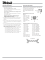
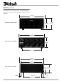
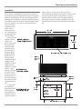
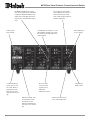
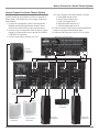
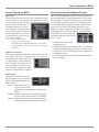
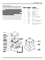
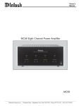
Eight Channel Power Amplifier
MC58
Owner’s Manual
McIntosh Laboratory, Inc. 2 Chambers Street Binghamton, New York 13903-2699 Phone: 607-723-3512 FAX: 607-724-0549
The lightning flash with arrowhead,
within an equilateral triangle, is intended
to alert the user to the presence of
uninsulated “dangerous voltage” within
the product’s enclosure that may be of
sufficient magnitude to constitute a risk
of electric shock to persons.
WARNING - TO REDUCE RISK OF
FIRE OR ELECTRICAL SHOCK, DO
NOT EXPOSE THIS EQUIPMENT TO
RAIN OR MOISTURE.
IMPORTANT SAFETY
INSTRUCTIONS!
PLEASE READ THEM BEFORE
OPERATING THIS EQUIPMENT.
1. Read these instructions.
2. Keep these instructions.
3. Heed all warnings.
4. Follow all instructions.
5. Do not use this apparatus near water.
6. Clean only with a dry cloth.
7. Do not block any ventilation openings. Install in
accordance with the manufacturer’s instructions.
8. Do not install near any heat sources such as
radiators, heat registers, stoves, or other
apparatus (including amplifiers) that produce
heat.
9. Do not defeat the safety purpose of the polarized
or grounding-type plug. A polarized plug has two
blades with one wider than the other. A grounding
type plug has two blades and a third grounding
prong. The wide blade or the third prong are
provided for your safety. If the provided plug
does not fit into your outlet, consult an electrician
for replacement of the obsolete outlet.
10. Protect the power cord from being walked on or
pinched particularly at plugs, convenience
receptacles, and the point where they exit from
the apparatus.
2
The exclamation point within an equilateral triangle is intended to alert the
user to the presence of important
operating and maintenance (servicing) instructions in the literature accompanying the appliance.
NO USER-SERVICEABLE PARTS
INSIDE. REFER SERVICING TO
QUALIFIED PERSONNEL.
To prevent the risk of electric shock, do not remove cover or
back. No user serviceable parts inside.
11. Only use attachments/accessories specified by the
manufacturer.
12. Use only with the cart, stand, tripod, bracket, or
table specified by the manufacturer,
or sold with the apparatus. When a
cart is used, use caution when moving
the cart/apparatus combination to
avoid injury from tip-over.
13. Unplug this apparatus during lightning storms or
when unused for long periods of time.
14. Refer all servicing to qualified service personnel.
Servicing is required when the apparatus has
been damaged in any way, such as power-supply
cord or plug is damaged, liquid has been spilled
or objects have fallen into the apparatus, the
apparatus has been exposed to rain or moisture,
does not operate normally, or has been dropped.
15. Do not expose this equipment to dripping or
splashing and ensure that no objects filled with
liquids, such as vases, are placed on the
equipment.
16. To completely disconnect this equipment from
the a.c. mains, disconnect the power supply cord
plug from the a.c. receptacle.
17. The mains plug of the power supply cord shall
remain readily operable.
Thank You
Table of Contents
Your decision to own this McIntosh MC58 Eight Channel
Power Amplifier ranks you at the very top among discriminating music listeners. You now have “The Best.” The
McIntosh dedication to “Quality,” is assurance that you
will receive many years of musical enjoyment from this
unit.
Please take a short time to read the information in this
manual. We want you to be as familiar as possible with all
the features and functions of your new McIntosh.
Thank You.......................................................................... 2
Safety Instructions ............................................................. 2
Thank You and Please Take a Moment .............................. 3
Technical Assistance and Customer Service ..................... 3
Table of Contents ............................................................... 3
Important Information ....................................................... 4
Connector Information ...................................................... 4
Introduction ....................................................................... 5
Performance Features ........................................................ 5
Dimensions ........................................................................ 6
Installation ......................................................................... 7
Rear Panel Controls, Connections and Switch .................. 8
How to Connect with a CR16 ............................................ 9
How to Connect two MC58s in Bridge Mode ................. 10
How to Connect in a Home Theater System ................... 11
Front Panel Displays and Controls .................................. 12
How to Operate ................................................................ 13
Specifications .................................................................. 14
Packing Instruction .......................................................... 15
Please Take A Moment
The serial number, purchase date and McIntosh Dealer
name are important to you for possible insurance claim or
future service. The spaces below have been provided for
you to record that information:
Serial Number:
Purchase Date:
Dealer Name:
Technical Assistance
If at any time you have questions about your McIntosh
product, contact your McIntosh Dealer who is familiar with
your McIntosh equipment and any other brands that may
be part of your system. If you or your Dealer wish additional help concerning a suspected problem, you can receive technical assistance for all McIntosh products at:
McIntosh Laboratory, Inc.
2 Chambers Street
Binghamton, New York 13903
Phone: 607-723-1545
Fax: 607-723-3636
Customer Service
If it is determined that your McIntosh product is in need of
repair, you can return it to your Dealer. You can also return
it to the McIntosh Laboratory Service Department. For assistance on factory repair return procedure, contact the
McIntosh Service Department at:
McIntosh Laboratory, Inc.
2 Chambers Street
Binghamton, New York 13903
Phone: 607-723-3515
Fax: 607-723-1917
Copyright 2004 © by McIntosh Laboratory, Inc.
3
Important Information
Connector Information
1. Connecting Cables and Connectors are available from the
McIntosh Parts Department:
Power Control Cable Part No. 170-202
Six foot, shielded 2 conductor, with 1/8 inch stereo mini
phone plugs on each end.
Control Center to Multichannel Power Amplifier Cable
Part No. 170-631
Six foot, DB25, shielded, straight through, 25 conductor
male-to-female cable.
Multizone Control System to Multichannel Power
Amplifier Cable Part No. 170-147
Six foot, 7Pin DIN, shielded, male-to-male cable.
2. For additional connection information, refer to the owner’s
manual(s) for any component(s) connected to the MC58
Amplifier.
3. There is a built-in turn on delay which will mute the speaker
outputs for approximately two seconds when the amplifier is
turned on.
4. It is very important that loudspeaker cables of adequate size
be used in your music system, to ensure that there will be no
power loss or heating. Cable size is specified in Gauge
numbers or AWG (American Wire Gauge). The smaller the
Gauge number, the larger the wire size:
If your loudspeaker cables are 25 feet (7.62m) or less,
use at least 18 Gauge (AWG) wire size or larger.
If your loudspeaker cables are 50 feet (38.1m) or less,
use at least 16 Gauge (AWG) wire size or larger.
If your loudspeaker cables are 100 feet (76.2m) or less,
use at least 14 Gauge (AWG) wire size or larger.
Power Control Connectors
The MC58’s Power Control Input uses a 5 volt signal. Use
a 1/8 inch stereo mini phone plug
to connect to the Power Control
Positive
Input on other McIntosh CompoN/C
nents.
Ground
Multi-Room Din Connector Pin
Layout
1. Zone 3-Pwr. Ctrl.
2. Zone 1-Pwr. Ctrl.
3. Pwr. Ctrl. (Main)
4. Zone 2-Pwr. Ctrl.
5. Video Power
6. Zone 4-Pwr. Ctrl.
7. Gnd.
8 Channel In DB25 Connector Pin Layout
1. Zone 2-Left
14. Zone 2-Left Gnd.
2. Zone 1-Left
15. Zone 1-Left Gnd.
3. Zone 2-Right
16. Zone 2-Right Gnd.
4. Zone 3-Left
17. Zone 3-Left Gnd.
5. Zone 1-Right
18. Zone 1-Right Gnd.
6. Zone 3-Right
19.Zone 3-Right Gnd.
7. Zone 4-Left
20. Zone 4-Left Gnd.
8. Zone 4-Right
21. Zone 4-Right Gnd.
9. N/C
22. N/C
10. N/C
23. Zone 3-Pwr. Ctrl.
11. Zone 1-Pwr. Ctrl.
24. Zone 4-Pwr. Ctrl.
12. Zone 2-Pwr. Ctrl.
25. Pwr. Ctrl. Gnd. (Main)
13. Pwr. Ctrl. (Main)
8 CHANNEL IN
4
Introduction and Performance Features
Introduction
Eight 50 watt McIntosh amplifier channels in one convenient package make the MC58 an ideal amplifier for a
multizone system. The MC58 can be configured in different Operating Modes to fit a wide range of uses where a
multichannel amplifier is required. For example, it has the
ability to bridge a pair of channels for 100 watts output.
Performance Features
•
Power Output
The MC58 consists of eight separate power amplifier channels, each capable of 50 watts into 4 ohm speakers with
less than 0.005% distortion. This is 400 watts of McIntosh
power in a single package.
•
Individual Channel or Bridged Pair Configuration
Each pair of MC58 amplifier channels can be operated
separately at 50 watts each, or bridged for 100 watts. The
MC58 is ideal for any application requiring a multichannel
power amplifier, such as a mulitzone system or home theater system.
•
Front Panel
The classic McIntosh Illuminated glass front panel includes
eight individual channel power guard indicators, four channel pair status indicators and a Power On/Off switch.
•
Power Guard
All eight channels include the patented McIntosh Power
Guard Circuit, that prevents the amplifier from being
overdriven into clipping with its harsh distorted sound that
can also damage your valuable loudspeakers.
•
Sentry Monitor
McIntosh Sentry Monitor power output stage protection
circuits are present on all eight channels to ensure the
MC58 will have a long and trouble free operating life.
•
Thermal Protection
Built-in thermal protection circuits guard against overheating which could shorten the normal long life expectancy of
your McIntosh power amplifier.
•
Direct Current Protection
Direct Current sensing circuits on each channel provide
extra protection for your valuable loudspeakers.
•
Convenient Single Cable Hookup
A rear panel connector provides for the convenience of using a single cable, (DB25 computer style) to receive all audio and power control signals from a McIntosh Multizone
Control System.
5
MC58 Dimensions
The following dimensions can assist in determining the
best location for your MC58. There is additional information on the next page pertaining to installing the MC58 into
cabinets.
17-1/2"
44.45cm
Front View of the MC58
7 -1/8"
18.10cm
7 -5/8"
19.37cm
17"
43.18cm
6 -5/16"
16.03cm
Rear View of the MC58
13 -1/4"
33.66cm
18-1/2"
46.99cm
17"
43.18cm
Side View of the MC58
13/16"
2.06cm
6
3/16" 6-1/2"
0.48cm 16.51cm
14-1/16"
35.72cm
7/8"
2.22cm
Dimensions and Installation
Installation
The MC58 can be placed upright on a table or shelf, standing on its four 1 inch high feet. The four feet may be removed from the bottom of the MC58 when it is custom installed as outlined below. The four feet together with the
mounting screws should be retained for possible future use
if the MC58 is removed from the custom installation and
used free standing. It also can be custom installed in a
piece of furniture
or cabinet of your
choice. The required panel cutout, ventilation cutout and unit dimensions are shown.
Always provide
adequate ventilation for your
MC58. Cool operation ensures the
longest possible
operating life for
any electronic instrument. Do not
install the MC58
directly above a
Cabinet
heat generating
Front
Panel
component such as
a high powered
amplifier. If all the
components are
installed in a single
cabinet, a quiet
running ventilation
fan can be a definite asset in maintaining all the sysSupport
tem components at
Shelf
the coolest possible
operating temperature.
A custom cabinet installation
1-1/4"
should provide the
3.18cm
following minimum spacing dimensions for cool
operation. Allow at
least 6 inches (15.24 cm) above the top, 2 inches
(3.81cm) below the bottom and 1 inch (2.54 cm) on each
side of the power amplifier, so that airflow is not obstructed. Allow 20 inches (50.8 cm) depth behind the
front panel. Be sure to cut out a ventilation hole in the
mounting shelf according to the dimensions in the drawing.
17-1/16"
43.34cm
MC58 Front Panel
Custom Cabinet Cutout
6 -5/8"
16.83cm
Cutout Opening for Custom Mounting
MC58 Side View
in Custom Cabinet
MC58 Bottom View
in Custom Cabinet
Cutout Opening for Ventilation
7/16"
1.11cm
12-1/16"
30.64cm
Cutout
Opening
for
Ventilation
12-11/16"
32.23cm
Chassis
Spacers
13-3/16"
33.50cm
15"
38.10cm
7
MC58 Rear Panel Controls, Connections and Switch
IN for discrete audio cables
from a Multizone Control or
Home Theater System and
OUT sends the input signal to
another component
POWER CONTROL IN receives
turn on/off signals from a McIntosh
component and the POWER CONTROL OUT sends that turn on/off
signal to the next McIntosh component
8 CHANNEL IN accepts a 25 conductor DB25 computer type cable
that connects all audio and power
control signals
Selects power
turn-on mode
Connect the MC58
power cord to a live
AC outlet. Refer to
information on the
back panel to determine the correct voltage
Receives zone
turn-on control
signals from a
McIntosh
Multizone system
Main Fuse holder, refer
to information on the
back panel of your
MC58 to determine the
correct fuse size and rating
8
Individual Input
Level controls
Channel pair
Mode switch
OUPUT Connections for
8 or 4 ohm loudspeakers
How to Connect with a CR16
How to Connect with a CR16
1. Connect the loudspeaker cables to the appropriate channel output connectors, being careful to observe the correct polarities.
2. Connect a single DB25 computer type cable from the
Multichannel Output of a Mutlizone Control System to
the MC58 8 CHANNEL INput connector for all eight
audio channels and power control.
McIntosh CR16 Multizone Control System
Note: Both audio and zone power control pass through this
cable. Discrete zone audio cables may also be used,
additionally connect a cable from the CR16 Din
Multichannel Amp connector to the matching
connector on the amplifier to provide Zone Power
Control.
3. Connect the MC58 power cord to a live AC outlet.
jfbattmr80
To AC Outlet
Zone Four
Left
Loudspeaker
Right
Loudspeaker
Zone Three
Left
Loudspeaker
Right
Loudspeaker
Zone Two
Left
Loudspeaker
Right
Loudspeaker
Zone One
Left
Loudspeaker
Right
Loudspeaker
9
How to Connect two MC58s in Bridge Mode
How to Connect two MC58s in Bridge Mode
The MC58 Eight Channel Power Amplifier has a Bridge
Mode, which doubles the power output for each of the four
Stereo Amplifier Pairs. Two MC58s, together with a CR16
provides higher power out for each of the four Zones.
Note: Only Zone One is illustrated below. Follow a similar
procedure for Zones Two through Four on the MC58.
1. Connect the Loudspeaker Cables to the appropriate
Bridged Channel Output Connections, being careful to
observe the correct polarities.
2. Connect a 7 Pin DIN cable from the Power Control
Output of a Multizone Control System to the MC58
MULTI-ROOM Connector (Left Channel Amplifier).
3. Connect a 7 Pin DIN cable from the Multichannel Output of a Multizone Control System to the MC58
MULTI-ROOM Connector (Right Channel Amplifier).
4. Connect an Audio Cable from the Zone 1 Left Channel
Unbalanced Output of a Multizone Control System, to
the MC58 IN 1 Connector (Left Channel Amplifier).
5. Connect an Audio Cable from the Zone 1 Right Channel Unbalanced Output of a Multizone Control System,
to the MC58 IN 1 Connector (Right Channel Amplifier).
6. Connect the MC58 power cord to a live AC outlet.
McIntosh CR16 Multizone Control System
Zone One
Left
Loudspeaker
To AC Outlet
Zone One
Right
Loudspeaker
To AC Outlet
10
How to Connect in a Home Theater System
How to Connect in a Home Theater System
The MC58 Eight Channel Power Amplifier can be used in
a Home Theater System with three of the six channels in
Bridge Mode. This doubles the power output for the three
front channels.
1. Connect the Loudspeaker Cables to the appropriate
Bridged and Non-Bridged Channel Output Connections, being careful to observe the correct polarities.
2. Connect a power control cable from the Power Control
Output of a Surround Decoder, to the MC58 POWER
CONTROL IN Connector.
3. Connect Audio Cables from the A/V Con-
trol Center Outputs to the MC58 Inputs as follows:
a. Front Right Output to IN 1
b. Front Center Output to IN 3
c. Front Left Output to IN 5
d. Right Surround Output to IN 7
e. Left Surround Output to IN 8
4. Connect an Audio Cable from the Surround Decoder
Outputs to the Powered Subwoofer Input.
5. Connect the MC58 power cord to a live AC outlet.
McIntosh A/V Control Center
Powered
Subwoofer
Loudspeaker
To AC Outlet
Center Channel
Loudspeaker
Left Surround
Loudspeaker
Right Surround
Loudspeaker
Left Front
Loudspeaker
Right Front
Loudspeaker
11
MC58 Front Panel Displays and Controls
POWER LED lights when
the Amplifier Channels 3
and 4 Circuits activate
POWER LED lights when
the Amplifier Channels 1
and 2 Circuits activate
POWER LED lights when
the Amplifier Channels 7
and 8 Circuits activate
POWER LED lights when
the Amplifier Channels 5
and 6 Circuits activate
Remote On
Indicator
POWER GUARD LEDs
light when the amplifier
channels 1 or 2 POWER
GUARD circuits activate
POWER GUARD LEDs
light when the amplifier
channels 3 or 4 POWER
GUARD circuits activate
12
POWER GUARD LEDs
light when the amplifier
channels 5 or 6 POWER
GUARD circuits activate
POWER Switch
Turns AC power
On/Off
POWER GUARD LEDs
light when the amplifier
channels 7 or 8 POWER
GUARD circuits activate
How to Operate the MC58
How to Operate the MC58
How to Operate with a Bridged Channel
Power On
To have the MC58 turn on or off when a multizone system
turns on or off, the front panel power switch must be left in
the on position and the rear panel
power control switch must be in
the remote position. For non-remote operation, set the rear panel
power control switch to local and
use the front panel power switch
to turn the MC58 on or off as desired. Refer to figure 1.
The versatile McIntosh MC58 can be used in three different Operating Modes. The four channel pairs can be used
in Stereo Mode to supply 50 watts of power to four zones
of a multizone system. Any of the four stereo pairs can be
set to Bridged Mode to supply 100 watts of power when
greater power is desired. The Mono Mode allows two
channels to supply identical mono audio to two separate
loudspeakers. A pair of MC58 channels in Bridged Mode
will produce 100 watts output into
an 8 ohm loudspeaker. Refer to figures 2, 3 and 4.
Note: There must be a power
Figure 1
control connection between
the MC58 and the McIntosh Multizone Control System
or Control Center in order for the remote power turn on
to function.
Input Level Controls
When using a McIntosh Multizone Control System or Control Center set all five level controls to the 2.5V position. If
a preamplifier or control center has a
1V output rating, set the controls to
the 1V position. If an increase or decrease in amplifier sensitivity is required for other applications, set the
Figure 2
controls as desired. Refer to figure 2.
1. Set the Mode switch to the
Figure 4
Bridged position.
2. Adjust the Bridged Level control to the 2.5V position if
using a McIntosh Multizone System or Control Center.
3. Connect the cable from the signal source component to
the Bridged In jack.
4. Connect loudspeaker cables to the terminals marked (-)
and (+) Bridged.
Mode Switch
The Mode switch allows a pair of
MC58 channels to be used in three
different operating configurations.
Refer to figure 3.
Stereo: Each channel of a steFigure 3
reo pair operates independently as left and right stereo 50 watt amplifiers.
Bridged: A channel pair operates in bridged configuration for a single monaural 100 watt amplifier.
Mono: Channel pair inputs are connected in parallel
resulting in identical outputs for each channel.
13
Specifications
Specifications
Power Output Per Channel
50 watts into 4 ohm load and 30 watts into 8 ohm load is
the minimum sine wave continuous average power output
per channel, all channels operating.
Power Output Bridged
100 watts into 8 ohm load is the minimum sine wave continuous average power output per channel, all channels operating.
Rated Power Band
20Hz to 20,000Hz
Total Harmonic Distortion
Maximum Total Harmonic Distortion at any power
level from 250 milliwatts to rated power output is:
0.005% for 4 ohm loads
0.005% for 8 ohm loads
0.005% for Bridged Mode with 8 ohm loads
Dynamic Headroom
1.8dB
Frequency Response
+0, -0.25dB from 20Hz to 20,000Hz
+0, -3.0dB from 10Hz to 100,000Hz
Sensitivity
1 volt (2.5V at level control center detent position)
A-Weighted Signal To Noise Ratio
92dB (112dB below rated output)
Wideband Damping Factor
100 @ 4 ohms
200 @ 8 ohms
Intermodulation Distortion
Maximum Intermodulation Distortion if instantaneous peak output per channel does not exceed
twice the rated output, for any combination of frequencies from 20Hz to 20,000Hz, with all channels
operating is:
0.005% for 4 ohm loads
0.005% for 8 ohm loads
0.005% for Bridged Mode with 8 ohm loads
Input Impedance
20,000 ohms
14
Power Requirements
100 Volts, 50/60Hz at 5.4 amps
110 Volts, 50/60Hz at 4.9 amps
120 Volts, 50/60Hz at 4.7 amps
220 Volts, 50/60Hz at 3.1 amps
230 Volts, 50/60Hz at 3.1 amps
240 Volts, 50/60Hz at 3.1 amps
Note: Refer to the rear panel of the MC58 for the correct
voltage.
Dimensions
Front Panel: 17-1/2 inches (44.5cm) wide, 7-1/16 inches
(17.9cm) high. Depth behind front mounting panel is 20
inches (50.8cm) including clearance for connectors. Panel
clearance required in front of mounting panel is 3/4 inches
(1.9cm).
Weight
40 pounds (18.1Kg) net, 58 pounds (28.3Kg) in shipping
carton
Packing Instructions
Packing Instructions
In the event it is necessary to repack the equipment for
shipment, the equipment must be packed exactly as shown
below. It is very important that the four plastic feet are attached to the bottom of the equipment. Three #10 x 2-1/4”
screws and washers must be used to fasten the unit securely
to the bottom pad and wood skid. This will ensure the
proper equipment location on the bottom pad. Failure to do
this will result in shipping damage.
Use the original shipping carton and interior parts only
if they are all in good serviceable condition. If a shipping
carton or any of the interior part(s) are needed, please call
or write Customer Service Department of McIntosh Laboratory. Please see the Part List for the correct part numbers.
Quantity
1
4
Part Number
033888
033887
Description
Shipping carton only
End cap (Foam pad)
1
1
1
2
1
2
2
033697
033725
034008
017218
033699
101169
104033
Inside carton only
Top Pad
Bottom pad
Plastic foot (spacer)
Wood skid
#10 x 2-¼” Wood screw
#10 x 1-¾” Wood screw
4
4
4
017218
100159
104083
Plastic foot
#10-32 x ¾” Machine screw
#10 x 7/16” Flat washer
1
040572
Shipping carton complete with
all the above parts
15
McIntosh Laboratory, Inc.
2 Chambers Street
Binghamton, NY 13903
The continuous improvement of its products is
the policy of McIntosh Laboratory Incorporated
who reserve the right to improve design without
notice.
Printed in the U.S.A.
McIntosh Part No. 04072601