1
YORK Solution
Air handling units
Installation and STARTUP INSTRUCTIONS
Supersedes 102.20-N1 (1108)
Form 102.20-N1 (1109)
YORK SOLUTION INDOOR AND OUTDOOR MODELS
s
al Part
w
e
n
e
R
P1
02.20-R
1
m
r
rts
o
F
alt. Pa
B
t
c
a
t
/N con
With P
2-1701
3
9
)
0
0
arts
(8
ialty p 14
c
e
p
s
d or
5-78
acture ide (800) 54
f
u
n
a
M
t Airs
contac
LD09624
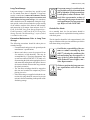
Indoor unit
LD09688
Outdoor unit
IMPORTANT!
Read BEFORE PROCEEDING!
GENERAL SAFETY GUIDELINES
This equipment is a relatively complicated apparatus.
During installation, operation, maintenance or service,
individuals may be exposed to certain components or
conditions including, but not limited to: refrigerants,
oils, and materials under pressure, rotating components,
and both high and low voltage. Each of these items
has the potential, if misused or handled improperly,
to cause bodily injury or death. It is the obligation
and responsibility of operating/service personnel to
identify and recognize these inherent hazards, protect
themselves, and proceed safely in completing their
tasks. Failure to comply with any of these requirements
could result in serious damage to the equipment and
the property in which it is situated, as well as severe
personal injury or death to themselves and people at
the site.
This document is intended for use by owner-authorized
operating/service personnel. It is expected that this
individual possesses independent training that will
enable them to perform their assigned tasks properly
and safely. It is essential that, prior to performing any
task on this equipment, this individual shall have read
and understood this document and any referenced
materials. This individual shall also be familiar with
and comply with all applicable governmental standards
and regulations pertaining to the task in question.
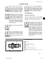
Safety symbols
The following symbols are used in this document to alert the reader to areas of concern:
DANGER indicates an imminently
hazardous situation, which if not
avoided, will result in death or serious injury.
WARNING indicates a potentially
hazardous situation, which if not
avoided, could result in death or serious injury.
CAUTION identifies a hazard which
could lead to damage to the machine,
damage to other equipment and/or
environmental pollution. Usually an
instruction will be given, together with
a brief explanation.
NOTE is used to highlight additional
information that may be helpful to
you.
Consider for IAQ compliance per
ASHRAE STANDARD 62-2001
IAQ
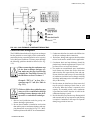
External wiring, unless specified as an optional connection in the manufacturer’s product
line, is not to be connected inside the control panel cabinet. Devices such as relays, switches,
transducers and controls may not be installed inside the control panel. No external wiring
is allowed to run through the control panel. All wiring must be in accordance with Johnson Controls published specifications and must be performed only by qualified Johnson
Controls personnel. Johnson Controls will not be responsible for damages/problems resulting from improper connections to the controls or application of improper control signals.
Failure to follow this will void the manufacturer’s warranty and cause serious damage to
property or injury to persons.
FORM 102.20-N1 (1109)
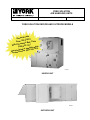
NOTICE TO CUSTOMER/CONTRACTOR
PROTECT YOUR WARRANTY PRIOR TO
STARTUP.
• Read and follow the Installation and Start-up
Instructions provided with this equipment.
• Storage of this equipment MUST be on a flat
surface and protected from the weather.
• Protect this equipment from damage, construction
dirt, debris and water.
DO NOT OPERATE DOORS WHEN UNIT
IS NOT ON A FLAT SURFACE.
• Isolate this equipment from pressure testing of
water, steam, gas and air piping.
• Do not test, clean and flush piping through coils
in this equipment.
• Isolate this equipment from temporary building
power.
• Contact local Johnson Controls Service for purchase of Startup Service with two weeks advance
notice. Provide current job site contact.
• To perform a careful and thorough startup, verify
the following:
– Reliable power will be available for
startup.
– Shipping splits completely re-assembled,
sealed and wired.
– Filters are installed and secured.
– All shipping materials have been removed.
METAL TAB USED TO SECURE
DOOR IS A SAFETY DEVICE. DO
NOT DISCARD IT.
– Start-up will be performed according to that
outlined in Section 3 of the Installation and
Start-up Instructions provided.
• Temporary use of air handler requires startup
performed according to that outlined in Section
3 of the Installation and Start-up Instructions
provided.
• A qualified startup technician must complete
the “AIR HANDLING UNITS START-UP
CHECK LIST” Form 100.00-CL1 and file a
copy at the local YORK Service Office. This
form is provided in the information package with
each air handler.
• Rotate fans every four (4) weeks beginning upon
arrival.
– Ductwork is complete.
– Controls are complete.
CHANGEABILITY OF THIS DOCUMENT
In complying with Johnson Controls policy for
continuous product improvement, the information
contained in this document is subject to change
without notice. While Johnson Controls makes no
commitment to update or provide current information
automatically to the manual owner, that information, if
applicable, can be obtained by contacting the nearest
Johnson Controls Service office.
johnson controls
It is the responsibility of operating/service personnel
to verify the applicability of these documents to the
equipment in question. If there is any question in
the mind of operating/service personnel as to the
applicability of these documents, then prior to working
on the equipment, they should verify with the owner
whether the equipment has been modified and if current
literature is available.
3
FORM 102.20-N1 (1109)
THIS PAGE INTENTIONALLY LEFT BLANK
4
johnson controls
FORM 102.20-N1 (1109)
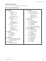
Table of contents
GENERAL SAFETY GUIDELINES.......................................................................................................................2
CHANGEABILITY OF THIS DOCUMENT............................................................................................................3
Table of contents........................................................................................................................................5
list of figures..............................................................................................................................................11
list of TABLES................................................................................................................................................15
introduction.................................................................................................................................................17
GENERAL....................................................................................................................................................17
TYPICAL YORK SOLUTION OPERATION IN “HVAC” SYSTEM...............................................................17
Ventilation System..................................................................................................................................17
Economizer System - Typical.................................................................................................................18
Heating Operation...................................................................................................................................18
Cooling Operation...................................................................................................................................18
HAND IDENTIFICATION..............................................................................................................................18
SEGMENT IDENTIFICATION.......................................................................................................................19
Unit Identification....................................................................................................................................21
Unit ID Label.......................................................................................................................................21
Skid ID Label......................................................................................................................................21
Segment Identification Box...............................................................................................................21
Loose Component ID Label..............................................................................................................22
Filter ID Label.....................................................................................................................................22
Direction of Airflow.................................................................................................................................22
1.0 pre-installation...................................................................................................................................1-1
RECEIVING.................................................................................................................................................1-1
RIGGING OF INDOOR AND OUTDOOR UNITS........................................................................................1-1
Off-Loading.............................................................................................................................................1-2
Crane And Spreader Bars.....................................................................................................................1-2
Fork Lift...................................................................................................................................................1-2
Come-A-Longs or Power Pull...............................................................................................................1-2
Shackles..................................................................................................................................................1-3
INSPECTION...............................................................................................................................................1-4
Check For Damage.................................................................................................................................1-4
Receiver Responsibility...................................................................................................................1-4
Indoor Units.......................................................................................................................................1-4
Outdoor Units....................................................................................................................................1-4
Checking for Non Mounted Parts.........................................................................................................1-4
STORAGE...................................................................................................................................................1-4
Short-Term Storage................................................................................................................................1-4
Long-Term Storage................................................................................................................................1-5
Preventive Maintenance Prior to Long Term Storage...................................................................1-5
Periodic Fan Check...........................................................................................................................1-5
johnson controls
5
FORM 102.20-N1 (1109)
Table of contents (Cont'D)
2.0 INSTALLATION............................................................................................................................................2-1
SITE PREPARATION..................................................................................................................................2-1
Outdoor Units (Site Prep)......................................................................................................................2-1
Mounting.......................................................................................................................................2-2
Curb..............................................................................................................................................2-2
Steel Frame..................................................................................................................................2-3
Indoor Units (Site Prep).........................................................................................................................2-3
Clearance...........................................................................................................................................2-5
Mounting............................................................................................................................................2-5
Floor..............................................................................................................................................2-5
Housekeeping Pad.......................................................................................................................2-5
Ceiling Suspended Units............................................................................................................2-6
UNIT INSTALLATION..................................................................................................................................2-7
Tools Needed..........................................................................................................................................2-7
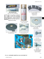
Ship Loose Parts....................................................................................................................................2-8
Assembly of Outdoor Unit...................................................................................................................2-13
Installing Single Piece Outdoor Unit.............................................................................................2-13
Installing Multiple Piece Outdoor Unit .........................................................................................2-13
Assembly of Indoor Unit......................................................................................................................2-17
Installing Multiple Piece Indoor Unit ............................................................................................2-17
Installation of Tiered Unit...............................................................................................................2-21
Assembly of End Channel Shipping Split....................................................................................2-23
HOOD INSTALLATION WITH OPTIONAL MIST ELIMINATORS.............................................................2-24
OUTDOOR AIR TEMPERATURE AND/OR HUMIDITY SENSORS.........................................................2-24
ACTUATOR INSTALLATION....................................................................................................................2-25
INSTALLATION OF MULTIZONE (MZ) DAMPERS..................................................................................2-26
Damper Installation..............................................................................................................................2-26
Actuator Installation Mutlizone (MZ) - Field Supplied......................................................................2-27
INERTIA FAN BASE FILL INSTRUCTION...............................................................................................2-27
HUMIDIFIERS............................................................................................................................................2-27
UVC EMITTER LIGHTS............................................................................................................................2-28
AIR MEASURING DEVICE CONNECTIONS (when provided)..........................................................2-29
Air Measuring at The Fan Inlets..........................................................................................................2-29
Air Measuring at Unit Inlets.................................................................................................................2-29
PIPE CHASE INSTALLATION..................................................................................................................2-30
Tools Required.....................................................................................................................................2-30
Materials Required...............................................................................................................................2-30
Procedure.............................................................................................................................................2-30
Condensate Drain Arrangement....................................................................................................2-35
ELECTRICAL - GENERAL........................................................................................................................2-36
6
johnson controls
FORM 102.20-N1 (1109)
Table of contents (Cont'D)
POWER CONNECTIONS..........................................................................................................................2-37
Single Point Power...............................................................................................................................2-37
Motors for Supply Fan, Return Fan, Exhaust Fan.............................................................................2-37
Energy Recovery Wheel Option..........................................................................................................2-37
Gas Heat Option...................................................................................................................................2-38
Electric Heat Option.............................................................................................................................2-39
Available Power Options................................................................................................................2-39
Electric Heat Disconnect Switch Options.....................................................................................2-39
Available Control Options..............................................................................................................2-40
Installation.......................................................................................................................................2-40
APPLICATION INFORMATION.................................................................................................................2-40
MECHANICAL INSTALLATION................................................................................................................2-40
ELECTRICAL INSTALLATION.................................................................................................................2-42
Humidifier Option (Electric)................................................................................................................2-43
Humidifier Option.................................................................................................................................2-43
PIPING CONNECTIONS...........................................................................................................................2-44
Coil Piping............................................................................................................................................2-45
Staggered Coils....................................................................................................................................2-45
Water................................................................................................................................................2-46
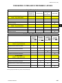
Water Coils - Hot Water and Chilled Water..............................................................................2-46
Hot and Chilled Water Coil Performance.................................................................................2-46
Water Treatment.........................................................................................................................2-48
Steam...............................................................................................................................................2-48
Steam Coils................................................................................................................................2-48
Steam Distributing Coils...........................................................................................................2-48
Steam Control............................................................................................................................2-48
Steam Traps...............................................................................................................................2-49
VIFB and IFB..............................................................................................................................2-50
Refrigeration....................................................................................................................................2-54
Direct Expansion Coils (DX).....................................................................................................2-54
DX Coil Types.............................................................................................................................2-55
Combined Coil Types................................................................................................................2-55
DX Coil Circuiting......................................................................................................................2-55
DX Coil Circuiting And Staging................................................................................................2-57
Thermostatic Expansion Valves (TXV)....................................................................................2-59
Hot Gas Bypass..............................................................................................................................2-59
Maintaining Adequate Airflow ................................................................................................2-59
VAV Systems..............................................................................................................................2-59
johnson controls
7
FORM 102.20-N1 (1109)
Table of contents (Cont'D)
Drains And Traps.................................................................................................................................2-61
Condensate Drain Piping...............................................................................................................2-61
Condensate Drain Trap...................................................................................................................2-61
Elevating Unit for Gravity Floor Drain Connections...............................................................2-62
Duct Connections................................................................................................................................2-62
Duct Connection Guidelines..........................................................................................................2-62
Duct Connections .....................................................................................................................2-63
Flanged Ducts or Sleeves ........................................................................................................2-63
Raw or Straight Edge Ducts or Sleeves..................................................................................2-63
Sound and Vibration Transmission...............................................................................................2-64
Front and Rear Discharge Outdoor Unit Duct Installation..........................................................2-64
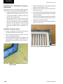
Air Filters..............................................................................................................................................2-65
Filter Types......................................................................................................................................2-65
Maintenance and Replacement.....................................................................................................2-65
Filter Latches...................................................................................................................................2-66
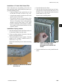
Installation of 2” Perfectpleat, Premium or Premium HM...........................................................2-68
Installation of Spring Latches .................................................................................................2-68
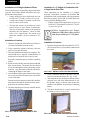
Installation of 4” Amair 300x Pleated Filter..................................................................................2-69
Installation of SH Single Headered Filters....................................................................................2-70
Installation of Latches . ............................................................................................................2-70
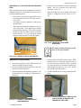
Installation of a 2” Prefilter In Combination with a Single Header Final Filter..........................2-70
Installation of Latches . ............................................................................................................2-70
Installation of a Varicel DH Double Headered Filter....................................................................2-71
Installation of Spring Latches .................................................................................................2-71
Installation of a 2” and 4" Prefilter in Combination With a Double Header Final Filter...........2-72
Installation of Spring Latches .................................................................................................2-72
Installation of Prefilter Latches ...............................................................................................2-72
HEPA Filters.....................................................................................................................................2-74
Welded Bevel Seal Frame.........................................................................................................2-74
Visual Control Filter Clamps.....................................................................................................2-74
8
johnson controls
FORM 102.20-N1 (1109)
Table of contents (Cont'D)
3.0 STARTUP.....................................................................................................................................................3-1
PRE START-UP...........................................................................................................................................3-2
PRE START UP FAN ASSEMBLY INSPECTION.......................................................................................3-3
Motors - ODP vs. TEFC . .......................................................................................................................3-3
Isolators..................................................................................................................................................3-4
Preparing Fan Isolators for Operation............................................................................................3-4
START-UP...................................................................................................................................................3-5
CHECK OPERATION OF FANS..............................................................................................................3-5
Check Operation of Dampers................................................................................................................3-5
Airflow Control Dampers..................................................................................................................3-5
Typical Actuators Locations............................................................................................................3-6
Basic Actuators Installation.............................................................................................................3-6
Damper Blade Orientation..........................................................................................................3-6
Energize Fan Motor(s)...........................................................................................................................3-7
Variable Speed Drive (VSD)...................................................................................................................3-7
Set Up of a Non-Factory Mounted VFD......................................................................................3-7
Check Doors and Latches for Proper Adjustment..............................................................................3-8
Sheaves...................................................................................................................................................3-8
General Guidelines for Replacing an Adjustable Sheave with a Fixed Sheave:.........................3-8
Energy Recovery Wheel........................................................................................................................3-9
Unit Configuration............................................................................................................................3-9
Indoor Units..................................................................................................................................3-9
Outdoor Units...............................................................................................................................3-9
Start-Up Procedure for Energy Recovery Wheel...........................................................................3-9
Indirect Fired Gas Heat Start Up.........................................................................................................3-11
Introduction.....................................................................................................................................3-11
Identify the Unit Type......................................................................................................................3-11
Preliminary Coordination...............................................................................................................3-12
Tools Recommended......................................................................................................................3-12
Air Handler Pre Start Checks.........................................................................................................3-12
Burner Pre Start Checks................................................................................................................3-12
Burner Start-Up Procedure............................................................................................................3-14
Condensate Drain Arrangement....................................................................................................3-15
Electric Heat Startup............................................................................................................................3-25
Airflow Requirements.....................................................................................................................3-25
johnson controls
9
FORM 102.20-N1 (1109)
THIS PAGE INTENTIONALLY LEFT BLANK
10
johnson controls
FORM 102.20-N1 (1109)
list of figures
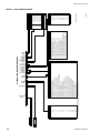
FIG. 1 – CUTAWAY OF YORK Solution SHOWING VARIOUS SEGMENTS.........................................17
FIG. 2 – UNIT AND COIL HAND IDENTIFICATION.....................................................................................18
FIG. 3 – UNIT ID LABEL..............................................................................................................................21
FIG. 4 – SKID ID LABEL..............................................................................................................................21
FIG. 5 – SEGMENT ID BOX EXAMPLE......................................................................................................21
FIG. 6 – LOOSE COMPONENT ID LABELS...............................................................................................22
FIG. 7 – filter LABELS............................................................................................................................22
FIG. 1-1 – RECOMMENDED LIFTING WITH FOUR LIFTING POINTS.....................................................1-1
FIG. 1-2 – RECOMMENDED LIFTING WITH MULTIPLE POINTS.............................................................1-1
FIG. 1-3 – TYPICAL COME-A-LONG TYPES............................................................................................1-2
FIG. 1-4 – P
ROPER LIFTING WITH SHACKLE AT CORNER...................................................................1-3
FIG. 1-5 – P
ROPER LIFTING WITH SHACKLE AT LIFTING LUG............................................................1-3
FIG. 1-6 – R
ECOMMENDED LIFTING WITH BASERAIL..........................................................................1-3
FIG. 1-7 – LONG-TERM STORAGE REQUIREMENT - FIELD PREPARATION.......................................1-6
FIG. 1-8 – LONG-TERM STORAGE PERIODIC CHECKLIST AND LOGS...............................................1-7
FIG. 2-1 – MINIMUM SERVICE CLEARANCES.........................................................................................2-1
FIG. 2-2 – TYPICAL CURB ASSEMBLY.....................................................................................................2-4
FIG. 2-3 – NO BASERAIL – HOUSEKEEPING PAD REQUIRED TO ACCOMMODATE
TRAP HEIGHT............................................................................................................................2-5
FIG. 2-4 – NO HOUSEKEEPING PAD – BASERAIL REQUIRED TO ACCOMMODATE
TRAP HEIGHT............................................................................................................................2-5
FIG. 2-5 – W
ITH BASERAIL AND HOUSEKEEPING PAD .......................................................................2-5
FIG. 2-6 – CEILING SUSPENDED UNIT....................................................................................................2-6
FIG. 2-7 – TOOLS TYPICALLY USED FOR ASSEMBLY OF SHIPPING SPLITS.....................................2-7
FIG. 2-8 – S
ECOND TIER TIE-DOWN FASTENER PACK P/n 386-03419-000........................................2-8
FIG. 2-9 – B
OTTOM RACEWAY SHIPPING SPLIT FASTENER PACKP/n 386-03418-000. ..........................2-8
FIG. 2-10 – B
ASERAIL SHIPPING SPLIT FASTENER PACK P/n 386-03417-000............................................2-8
FIG. 2-11 – TOP RACEWAY SPLIT FASTENER PACK.............................................................................2-8
FIG. 2-12 – PIPE CHASE, HOODS & SEAM CAPS...................................................................................2-9
FIG. 2-13 – Miscellaneous parts for Options..........................................................................2-10
FIG. 2-14 – HARDWARE, GASKETING, CAULK, PAINT AND TAPE.....................................................2-11
FIG. 2-15 – SHIPPING SPLIT EXAMPLES...............................................................................................2-12
FIG. 2-16 – SHIPPING SPLIT EXAMPLES FOR EXPANDED CABINET................................................2-12
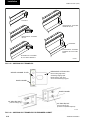
FIG. 2-17 – APPLYING GASKET..............................................................................................................2-14
FIG. 2-18 – ELECTRICAL CONNECTIONS.............................................................................................2-14
FIG. 2-19 – R
EMOVE AND REPOSITION SHIPPING SPLIT ANGLE.....................................................2-15
FIG. 2-20 – BRINGING SECTIONS TOGETHER.....................................................................................2-16
FIG. 2-21 – APPLYING GASKET TO SHIPPINGSPLIT............................................................................2-17
FIG. 2-22 – APPLYING GASKET TO DOOR FRAMEWHEN AT SHIPPING SPLIT.................................2-17
FIG. 2-23 – ASSEMBLY OF END CHANNEL SHIPPING SPLIT (EXPANDED CABINET)......................2-18
FIG. 2-24 – R
EMOVE AND REPOSITION SHIPPING SPLIT ANGLE.....................................................2-18
FIG. 2-25 – P
lacing and anchoring first section and attaching come-a-longs........2-19
FIG. 2-26 – R
EMOVE LIFTING LUGS AND SAVE HARDWARE.............................................................2-19
FIG. 2-27 – ELECTRICAL CONNECTIONS.............................................................................................2-19
johnson controls
11
FORM 102.20-N1 (1109)
list of figures (Cont'D)
FIG. 2-28 – installing bolts after pulling units tight together...................................2-20
FIG. 2-29 – TIERED UNIT.........................................................................................................................2-21
FIG. 2-30 – TIERED UNIT SECURED WITH BRACKETS.......................................................................2-21
FIG. 2-31 – APPLY GASKETS TO TOP PANEL BOTTOM TIER.............................................................2-21
FIG. 2-32 – GUIDING BRACKETS TOGETHER......................................................................................2-22
FIG. 2-33 – ASSEMBLY OF END CHANNEL SHIPPING SPLIT..............................................................2-23
FIG. 2-34 – HOOD INSTALLATION WITH OPTIONAL MIST ELIMINATORS.........................................2-24
FIG. 2-35 – DIRECT COUPLED ON JACKSHAFT...................................................................................2-25
FIG. 2-36 – MZ DAMPER/ACTUATOR ASSEMBLY.................................................................................2-26
FIG. 2-37 – DAMPER SHAFT EXTENSION KIT.......................................................................................2-27
FIG. 2-38 – V-MOD INSTALLATION.........................................................................................................2-28
FIG. 2-39 – V-RAY INSTALLATION..........................................................................................................2-28
FIG. 2-40 – V-FLEX INSTALLATION........................................................................................................2-28
FIG. 2-41 – INSTALL GASKET UNDER ROOF OVERHANG..................................................................2-30
FIG. 2-42 – APPLY GASKET TO PIPE CHASE........................................................................................2-31
FIG. 2-43 – P
IPE CHASE BASERAIL TO UNIT BASERAIL INSTALLATION ........................................2-31
FIG. 2-44 – S
CREW PIPE CHASE TOP AND BOTTOM INTERNAL FLANGES TO AIR HANDLER ...... 2-31
FIG. 2-45 – BASERAIL CAULK APPLICATION...........................................................................................2-32
FIG. 2-46 – P
IPE CHASE TO ROOF INSTALLATION..............................................................................2-32
FIG. 2-47 – P
IPE CHASE TO AIR HANDLER CAULK APPLICATION.......................................................2-32
FIG. 2-48 – INSTALL COVER ANGLE......................................................................................................2-32
FIG. 2-49 – P
ROPER POSITIONING OF COVER ANGLE WITH NOTCH ON AIR HANDLER SIDE....... 2-33
FIG. 2-50 – P
ROPER PATTERN FOR INSTALLING SELF-DRILLING SCREWS TO
COVER ANGLE......................................................................................................................2-33
FIG. 2-51 – BASERAIL COVER APPLICATION.......................................................................................2-33
FIG. 2-52 – GAS FURNACE FUEL VENTING SYSTEM..........................................................................2-34
FIG. 2-53 – GAS FURNACE Condensate drain trap....................................................................2-35
FIG. 2-54 – TYPICAL MOTOR DATA / NAMEPLATE...............................................................................2-37
FIG. 2-55 – TYPICAL POWER WIRING OF ENERGY RECOVERY WHEEL..........................................2-37
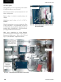
FIG. 2-56 – GAS BURNER COMPONENT LOCATIONS.........................................................................2-38
FIG. 2-57 – M
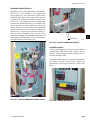
AIN POWER AND CONTROL PANEL W/ COVER OPEN.................................................2-38
FIG. 2-58 – TYPICAL ELECTRIC HEAT CONTROL PANEL INTERIOR WIRING AND
COMPONENTS......................................................................................................................2-39
FIG. 2-59 – TYPICAL FIELD CONTROL AND POWER CONNECTIONS................................................2-39
FIG. 2-60 – P
RESSURE PROBE DIRECTION.........................................................................................2-41
FIG. 2-61 – AIRFLOW SWITCH CONNECTIONS....................................................................................2-41
FIG. 2-62 – TYPICAL HUMIDIFIER PANEL LAYOUT..............................................................................2-43
FIG. 2-63 – SUPPLY POWER KNOCKOUTS...........................................................................................2-43
FIG. 2-64 – HUMIDIFIER POINTS............................................................................................................2-43
FIG. 2-65 – PIPE CHASE ENCLOSURE .................................................................................................2-44
FIG. 2-66 – FACTORY COIL CONNECTIONS..........................................................................................2-44
FIG. 2-67 – STAGGERED COIL CONFIGURATIONS..............................................................................2-45
FIG. 2-68 – CHILLED WATER COIL CONNECTIONS.............................................................................2-46
FIG. 2-69 – HOT WATER PIPING - 2 WAY VALVE...................................................................................2-47
12
johnson controls
FORM 102.20-N1 (1109)
list of figures (Cont'D)
FIG. 2-70 – HOT WATER PIPING WITH DIVERTING VALVE..................................................................2-47
FIG. 2-71 – STEAM COIL PIPING ARRANGEMENTS.............................................................................2-49
FIG. 2-72 – INTEGRAL FACE and BYPASS COIL (HORIZONTAL; TUBES, STEAM SHOWN)...........2-50
FIG. 2-73 – V
ERTICAL INTEGRAL FACE and BYPASS COIL .............................................................2-50
FIG. 2-74 – HOT WATER PIPING FOR 2 ROW COIL VIFB.....................................................................2-52
FIG. 2-75 – HOT WATER PIPING FOR IFB..............................................................................................2-52
FIG. 2-76 – STEAM PIPING FOR VIFB COIL...........................................................................................2-53
FIG. 2-77 – TYPICAL PIPING AND SUNDRIES AT THE DX COIL..........................................................2-54
FIG. 2-78 – DX COIL CIRCUITING TYPES .............................................................................................2-55
FIG. 2-79 – NON-STACKED COIL DESIGN - SQ SPECIAL....................................................................2-56
FIG. 2-80 – NON-STACKED COIL DESIGN - STANDARD......................................................................2-56
FIG. 2-81 – STACKED COIL DESIGN - STANDARD...............................................................................2-57
FIG. 2-82 – STACKED COIL DESIGNS - SQ SPECIAL...........................................................................2-57
FIG. 2-83 – STACKED COIL CIRCUITING...............................................................................................2-57
FIG. 2-84 – O
NE COIL CIRCUIT PERREFRIGERANT CIRCUIT.............................................................2-58
FIG. 2-85 – TWO COIL CIRCUITS PERREFRIGERANT CIRCUIT..........................................................2-58
FIG. 2-86 – DO NOT USE THE ABOVE CONFIGURATION....................................................................2-58
FIG. 2-87 – THREE COMPRESSOR YCUL..............................................................................................2-58
FIG. 2-88 – DO NOT USE THE ABOVE CONFIGURATION....................................................................2-58
FIG. 2-89 – SIX COMPRESSOR YCUL....................................................................................................2-59
FIG. 2-90 – DRAIN TRAP SHOWING WATER LOCATION DURING DRAW THROUGH
OPERATION STAGES...........................................................................................................2-61
FIG. 2-91 – TRAP DETAIL FOR DRAW THROUGH APPLICATION........................................................2-61
FIG. 2-92 – TRAP DETAIL FOR BLOW THROUGH APPLICATION........................................................2-61
FIG. 2-93 – COMBINING DRAIN LINES...................................................................................................2-62
FIG. 2-94 – R
ECOMMENDED DISCHARGE DUCT ARRANGEMENT WHEN TURNS
ARE REQUIRED.....................................................................................................................2-62
FIG. 2-95 – R
ECOMMENDED DISCHARGE DUCT ARRANGEMENT WHEN TURNS
ARE REQUIRED.....................................................................................................................2-63
FIG. 2-96 – DUCT PENETRATION OF ROOF..........................................................................................2-64
FIG. 2-97 – R
OOF TO DUCT INSTALLATION - HORIZONTAL DISCHARGE.........................................2-64
FIG. 2-97A – TYPICAL FILTERS..............................................................................................................2-65
Fig. 2-98 – Filter Latches..................................................................................................................2-66
Fig. 2-99 – C
orrectly installed latch P/N 026-35778-000........................................................2-68
Fig. 2-100 – Fully installed filter................................................................................................2-68
Fig. 2-101 – Correctly installed latch P/N 026-35778-007......................................................2-69
Fig. 2-102 – Place the end of the latch over the filter frame, securing
the filter to the frame..............................................................................................2-69
Fig. 2-103 – installed CARTRIDGE filter......................................................................................2-70
Fig. 2-104 – install latch p//n 026-35778-007.................................................................................2-70
Fig. 2-105 – installed CARTRIGE W/PLEATS...................................................................................2-70
Fig. 2-106 – CORRECT USE OF KNOCKOUTS.....................................................................................2-71
Fig. 2-107 – Correct latch/knockout configuration. ........................................................2-71
johnson controls
13
FORM 102.20-N1 (1109)
list of figures (Cont'D)
Fig. 2-108 – F
rame with 4 latches installed. ...........................................................................2-71
Fig. 2-109 – S
pring latch should be pulled and fastened in hole in the
header of the filter...................................................................................................2-71
Fig. 2-110 – C
orrect latch/knockout configuration. P/N 026-35778-006.........................2-72
Fig. 2-111 – Frame with 4 latches installed ............................................................................2-72
Fig. 2-112 – P
refilter latch after Installation onto filter header.............................2-72
Fig. 2-113 – P
osition prefilter in front of the final filter.
(2" w/026-36339-000 latch shown)...............................................................................2-73
Fig. 2-114 – S
pring the end of the latch so that it fits over the edge of
the Prefilter. (4" w/026-36339-000 latch shown).................................................2-73
Fig. 2-115 – Completed assembly...................................................................................................2-73
FIG. 2-116 – HEPA FILTER FRAME CROSS SECTION VIEW................................................................2-74
FIG. 2-117 – VISUAL CONTROL FILTER CLAMPS.................................................................................2-74
FIG. 2-118 – HEPA FILTER INSTALLATION............................................................................................2-75
FIG. 2-119 – WELDED BEVEL SEAL FILTER INSTALLATION...............................................................2-75
FIG. 3-1 – TERMINATION CHART INSIDE ENCLOSURE DOOR.............................................................3-2
FIG. 3-2 – F
AN AND MOTOR ISOLATOR SUPPORT FRAME..................................................................3-3
FIG. 3-3 – ODP (OPEN DRIP PROOF).......................................................................................................3-3
FIG. 3-4 – TEFC (TOTALLY ENCLOSED FAN COOLED)..........................................................................3-4
FIG. 3-5 – SPRING ISOLATOR...................................................................................................................3-4
FIG. 3-6 – SEISMIC SNUBBER..................................................................................................................3-4
FIG. 3-7 – E
XAMPLE OF SWEEP BALANCE RESULTS..........................................................................3-7
FIG. 3-8 – TYPICAL DRIVE KIT DATA TAG...............................................................................................3-8
FIG. 3-9 – INDOOR UNIT - VERTICAL WHEEL.........................................................................................3-9
FIG. 3-10 – OUTDOOR UNIT - HORIZONTAL WHEEL..............................................................................3-9
FIG. 3-11 – ENERGY RECOVERY WHEEL - PULLEY SIDE...................................................................3-10
FIG. 3-12 – SEGMENT RETAINER...........................................................................................................3-10
FIG. 3-13 – DIAMETER SEAL ADJUSTMENT.........................................................................................3-10
FIG. 3-14 – OPEN FUSE DISCONNECTS................................................................................................3-12
FIG. 3-15 – sET ID FAN DAMPER...........................................................................................................3-13
FIG. 3-16 – C
HECK MAIN GAS SUPPLY PRESSURE............................................................................3-13
FIG. 3-17 – DRAFT OVER FIRE test port..........................................................................................3-14
FIG. 3-18 – F
LUE (STACK) combustion tEMPERATURE and efficiency test port.............3-14
FIG. 3-19 – DAMPER ACTUATOR...........................................................................................................3-15
FIG. 3-20 – CONDENSATE DRAIN .........................................................................................................3-15
FIG. 3-21 – GAS FURNACE Condensate drain trap....................................................................3-16
FIG. 3-22 – GAS FURNACE FUEL VENTING SYSTEM..........................................................................3-20
FIG. 3-23 – GAS FURNACE FUEL VENTING SYSTEM..........................................................................3-21
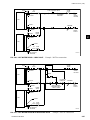
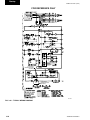
FIG. 3-24 – typical wiring diagram................................................................................................3-22
fIG. 3-25 – MINIMUM AIR VELOCITY REQUIRED FOR SAFE OPERATION........................................3-25
FIG. 3-26 – PRESSURE PROBE DIRECTION.........................................................................................3-26
FIG. 3-27 – AIRFLOW SWITCH CONNECTIONS....................................................................................3-26
FIG. 3-28 – AIR handler start-up checklist...............................................................................3-27
14
johnson controls
FORM 102.20-N1 (1109)
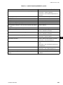
list of TABLES
TABLE 1 – SEGMENT IDENTIFICATION....................................................................................................17
TABLE 2 – UNIT NOMENCLATURE............................................................................................................18
TABLE 1-1 - SPACING REQUIREMENTS FOR OFFLOADING LONG UNITS.........................................1-2
TABLE 3-1 – TORQUE FOR TIGHTENING SETSCREWS........................................................................3-3
TABLE 3-2 – NATURAL GAS PRESSURE REQUIREMENTS (INCHES WC)........................................3-18
TABLE 3-3 – P
IPE SIZE REQUIRED........................................................................................................3-19
Table 3-4 – B
URNER TEPERATURE RISE...........................................................................................3-23
TABLE 3-5 – INSPECTION REQUIREMENTS.........................................................................................3-29
johnson controls
15
FORM 102.20-N1 (1109)
THIS PAGE INTENTIONALLY LEFT BLANK
16
johnson controls
FORM 102.20-N1 (1109)
introduction
GENERAL
This manual has been prepared as a guide for
installing, operating and maintaining YORK Solution
Air Handling Units. Johnson Controls has produced a
quality product that is adaptable to almost any comfort
or industrial application. However, proper installation,
operation and maintenance must be followed to realize
the full capacity and life of the units.
This instruction contains general recommendations,
but specific requirements may apply to the individual
installation. Such requirements are outlined in federal,
state and local safety codes. Strict compliance with these
codes and strict adherence to these instructions are the
responsibility of the user. Particular attention should
be given to electrical wiring and other safety elements
such as design working pressures and requirements
of the Government Clean Air Act Amendments as it
applies to refrigerant types and charges. General safety
practices are covered in AMCA Publication 410-90.
Read the entire instruction before installing or operating
the air handler. Specific details and requirements apply
that require careful consideration to avoid damage to
the equipment and injury to the installer or operator.
TYPICAL YORK SOLUTION OPERATION IN
“HVAC” SYSTEM
The operation of these units can be divided into systems:
1. Ventilation system.
2. Economizer system (return air/mixing box section).
3. Heating system.
4. Cooling system.
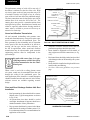
Ventilation System
A ventilation system simply replaces the air in a given
space. Usually the purpose is to remove air that is
substandard to creature comfort or a process and replace
it with suitable air. Depending on the application the
system will operate at various specified rates, volumes
and conditions. A ventilation system may employ an air
handler with a supply fan working in conjunction with
other remote exhaust fan(s). A more effective method
would employ both a supply fan and an exhaust fan in
the air handler.
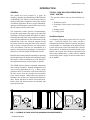
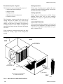
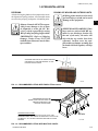
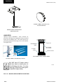
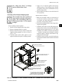
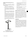
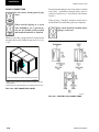
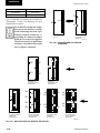
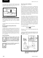
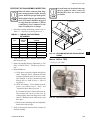
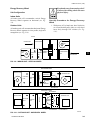
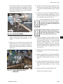
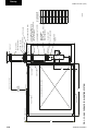
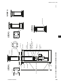
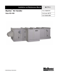
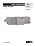
The YORK Solution features segmented construction
and is factory assembled. Segment arrangements will
vary to suit job application (see Fig. 1). Heavy gauge
galvanized steel is used on the exterior and interior of
the unit. Access doors are provided for accessibility
to the various sections. Removable access panels are
standard in lieu of doors on Commercial Performance
units. Panels and doors are double wall construction.
Panels, doors and structural frame are insulated with
spray-injected foam.
LD13764
FIG. 1 – CUTAWAY OF YORK Solution SHOWING VARIOUS SEGMENTS
johnson controls
17
FORM 102.20-N1 (1109)
Economizer System - Typical
Heating Operation
The Economizer system could typically consist of:
• Outdoor and return air dampers.
• Damper actuator.
• Enthalpy control.
• Minimum outdoor air adjustment.
• Exhaust air control.
Various types of heating may be applied. Hot water
or steam coils maybe specified typically. Electric heat
and fuel burner heat are available.
The Economizer system provides the first stage of
cooling whenever the outdoor air is cool and dry
enough to satisfy the internal cooling demand. The
outdoor and the return air dampers are operated by
individual actuators. As the outdoor air dampers are
opened by the damper actuator, the return air dampers
are closed.
Cooling Operation
Various types of cooling may be utilized. Factory
mounted chilled water coils or direct expansion
refrigerant coils may be specified for the YORK
Solution unit.
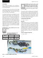
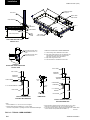
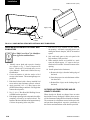
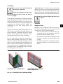
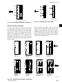
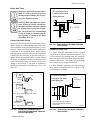
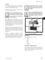
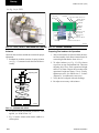
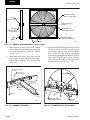
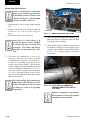
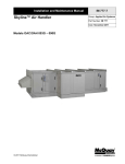
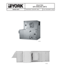
HAND IDENTIFICATION
Coil connections and other components are located and
described as left or right hand. The proper orientation
to describe the proper hand is when airflow is at your
back, as shown in Fig. 2.
If the economizer operation cannot satisfy the space
demand for cooling, stages can be energized as
needed.
FaN SectioN
Right
REAR
riGht haND (rh)
coiL coNNectioN
LeFt haND (Lh)
coiL coNNectioN
retUrN air
lEFt
oUtSiDe air
iNLet SectioN
Drive haND aND coiL haND DeterMiNeD
BY FaciNG the iNLet SectioN
FROnt
LD08004
FIG. 2 – UNIT AND COIL HAND IDENTIFICATION
18
johnson controls
FORM 102.20-N1 (1109)
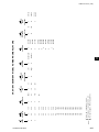
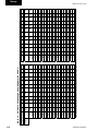
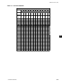
SEGMENT IDENTIFICATION
Refer to Tables 1 and 2 for segment identification and nomenclature.
TABLE 1 – SEGMENT IDENTIFICATION
FAN SEGMENTS
• FS – Supply
FILTER SEGMENTS
• FF – Flat Filter (2" or 4")
• Forward Curved
• AF – Angle Filter (2" & 4")
• Airfoil
• RF – High Efficiency Filter
• Industrial Airfoil
• Rigid Filter (12")
• SWSI Plenum
• Bag Filter (21")
(Belt and Direct Drive)
• Mini-Pleat Filter (4")
• FR – Return
• Forward Curved
• HF – HEPA Filter
INLET SEGMENTS
• Airfoil
• MB – Mixing Box
• Industrial Airfoil
• FM – Filter/Mixing Box
• SWSI Plenum
• EF – Filter/Economizer
(Belt and Direct Drive)
• EE – Economizer
• FE – Exhaust
• IP – Inlet Plenum
• Forward Curved
• VE – Vertical Economizer
• Airfoil
• VF – Vertical Filter/Economizer
• Industrial Airfoil
ACCESSORY SEGMENTS
• SWSI Plenum
• VP – Vertical Plenum
(Belt and Direct Drive)
• DP – Discharge Plenum
COIL SEGMENTS
• TN – Turning Plenum
• CC – Cooling Coil
• DI – Diffuser
• HC – Heating Coil
• XA – Access segment
• VC – Vertical Coil
• AB- Air Blender
• MZ - Multizone
• EB – External Bypass
HEAT SEGMENTS
• IB – Internal Bypass
• IC – Integral Face & Bypass Coil
• FD – Face Damper
• IG – Indirect Gas Fired Furnace
• AT – Attenuator
• EH – Electric Heater
• HM - Humidifier
ENERGY RECOVERY
• UV - UVC Lamps
• ER – Energy Recovery
johnson controls
19
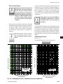
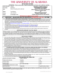
I INDOOR UNIT
O OUTDOOR UNIT
XT
I - 048 X 075 - D
NOMINAL
WIDTH
NOMINAL
HEIGHT
PRIMARY
IDENTIFIER
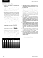
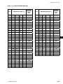
H
WIDTH
27
27,30,33,36,39,42,45,48,51,54,57
30
27,30,33,36,39,42,45,48,51,54,57,60
33
30,33,36,39,42,45,48,51,54,57,60,63,66,69
30,33,36,39,42,45,48,51,54,57,60,63,66,69,72
36
39
33,36,39,42,45,48,51,54,57,60,63,66,69,72,75,78
42
36,39,42,45,48,51,54,57,60,63,66,69,72,75,78,81,84
45
36,39,42,45,48,51,54,57,60,63,66,69,72,75,78,81,84,87
48
39,42,45,48,51,54,57,60,63,66,69,72,75,78,81,87,90
51
42,45,48,51,54,57,60,63,66,69,72,75,78,81,84,87,90,93,96,99
54
45,48,51,54,57,60,63,66,69,72,75,78,81,84,87,90,93,96,99,102
57
48,54,60,66,72,78,84,90,102,108
60
48,54,60,66,72,78,81,84,90,96,102,108
63
51,57,63,69,75,81,87,90,93,99,105,111,117
66
54,60,66,72,78,84,90,96,102,108,114,120
69
51,57,63,69,75,81,87,93,96,99,105,108,111,117,123
72
54,60,66,72,78,84,90,96,102,108,114,120,126,132
75
57,63,69,75,81,87,93,99,105,111,117,120,123,129,135
78
60,66,72,78,84,90,96,102,108,114,120,126,132,138,144
84
60,66,72,78,84,90,96,102,108,114,120,126,132,138,144
90
66,72,78,84,90,96,102,108,114,120,126,132,138,144
96
72,78,84,90,96,102,108,114,120,126,132,138,144
102
72,78,84,90,96,102,108,114,120,126,132,138,144
108
78,84,90,96,102,108,114,120,126,132,138,144
114
84,90,96,102,108,114,120,126,132,138,144
120
90,96,102,108,114,120,126,132,138,144
126
90,96,102,108,114,120,126,132,138,144
132
96,102,108,114,120,126,132,138
Notes: 1.The height and width numbers only correspond to each other in the same row.
2. The height and width numbers will always be (3) characters long in the model number.
ENVIRONMENT
XT
RETURN FAN
MOTOR HP
RETURN FAN
OPTIONS
SUPPLY FAN
MOTOR HP
C M K
0
FACTORY
MOUNTED END
DEVICES
SUPPLY FAN
OPTIONS
20
A
B
C
D
E
F
G
H
J
K
L
M
N
P
Q
R
S
A
DESIGN
SERIES
FAN OPTIONS
NONE.
DWDI FC FAN w/o MOTOR CONTROLLER.
DWDI FC FAN w/SERVICE DISCONNECT ONLY.
DWDI FC FAN w/MOTOR STARTER.
DWDI FC FAN w/VARIABLE FREQUENCY DRIVE.
DWDI AF FAN w/o MOTOR CONTROLLER.
DWDI AF FAN w/SERVICE DISCONNECT ONLY.
DWDI AF FAN w/MOTOR STARTER.
DWDI AF FAN w/VARIABLE FREQUENCY DRIVE.
SWSI PL FAN w/o MOTOR CONTROLLER.
SWSI PL FAN w/SERVICE DISCONNECT ONLY.
SWSI PL FAN w/MOTOR STARTER.
SWSI PL FAN w/VARIABLE FREQUENCY DRIVE.
SWSI PL FAN DIRECT DRIVE w/o MOTOR CONTROLLER.
SWSI PL FAN DIRECT DRIVE w/SERVICE DISCONNECT ONLY.
SWSI PL FAN DIRECT DRIVE w/MOTOR STARTER.
SWSI PL FAN DIRECT DRIVE w/VARIABLE FREQUENCY DRIVE.
46
PRIMARY
VOLTAGE
CODE
Solution Unit Model Number.
NAMEPLATE VOLTAGE
120 - 1 - 60
200 or 208 - 3 - 60
277 - 1 - 60
230 or 240 - 3 - 60
380 - 3 - 60
440-3-50
460 - 3 - 60
380 or 415 - 3 - 50
575 - 3 - 60
220 - 3 - 50
DEFINITION
ORIGINAL UNIT DESIGN
LD13350
003-001.xls Rev New
MOTOR HORSEPOWER
A0
B 1/2
C 3/4
D1
E 1 1/2
F2
G3
H5
J 7 1/2
K 10
L 15
M 20
N 25
P 30
Q 40
R 50
S 60
T 75
U 100
V 125
FACTORY MOUNT END DEVICES.
0 NO
1 YES
CODE
12
17
27
28
40
44
46
50
58
63
DESIGN
A
FORM 102.20-N1 (1109)
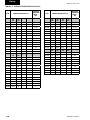
TABLE 2 – UNIT NOMENCLATURE
johnson controls
FORM 102.20-N1 (1109)
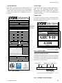
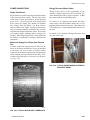
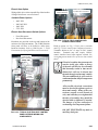
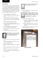
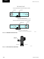
Unit Identification
Unit ID Label
Both indoor and outdoor units are labeled with a Unit
ID Label, Skid ID Labels and Loose Component ID
Labels. Indoor units are shrink wrapped with Skid ID
Labels on the outside of the wrapping as well as on
each skid.
The Unit ID Label contains the Model number, Serial/
Date Code, Job Identification number, Segment
Identification, the number of Skids, Unit Tag number,
Electrical Ratings, Coil Data and Manufacturing
Location (see Fig. 3).
Skid ID Label
THIS PRODUCT MANUFACTURED FOR
UNIT ID.
Each skid in a multi piece unit is marked with a Skid
ID Label, which indicates its order of assembly in the
direction of airflow (see Fig. 4).
OUTDOOR USE
MODEL #
COM : 117817
XTO-108X120-JJRN046A
SERIAL # / DATE CODE
JOB IDENTIFICATION #
CHTM XT0085
08-179121-01-01
SEGMENT IDENTIFICATION
(FS)(CC-HM)(XA-IC-XA-RF)(EE)(FR)
# OF SKIDS
UNIT TAG #
5
AHU 9-10
See Fig. 5 for
Segment ID
explanation
ELECTRICAL RATINGS
72
38
SKID
150
N/A
N/A
N/A
M.C.A.
AHU 9-10
JOB NAME
SKID OVERALL SIZE
116 H x 120 W x 59 L
Estimated Weight:
GAS HEAT RATINGS
N/A
120/1/60
5
AHU 9-10
4,100
80
N/A
LIGHTS & OUTLETS
VOLTS / PH / HZ
of
MAX. O.C. PROT.
47.5
ELECTRIC HEAT RATINGS
UNIT TAG
1
Owens Corning BLDG-21
MAX. O.C. PROT.
90
HEAT RECOVERY WHEEL MOTOR RATING (INDIVIDUAL LOAD)
HP
FLA
M.C.A.
MAX. O.C. PROT.
N/A
08-179121-01-01
(FS)(CC-HM)(XA-IC-XA-RF)(EE)(FR)
_____
RETURN FAN MOTOR RATING (INDIVIDUAL LOAD)
HP
FLA
M.C.A.
25
JOB IDENTIFICATION #
CHTM XT0085
MAX. O.C. PROT.
_____
SUPPLY FAN MOTOR RATING (INDIVIDUAL LOAD)
HP
FLA
M.C.A.
50
SERIAL # / DATE CODE
SEGMENT IDENTIFICATION
TOTAL RATINGS (COMBINED LOADS)
VOLTS / PH / HZ
M.C.A.
460/3/60
COM : 117817
MODEL #
XTO-108X120-JJRN046A
MAX. O.C. PROT.
20
20
pounds
COIL DATA
HOT WATER COIL MAX. INLET WATER TEMP.
STEAM COIL MAX. OPERATING PRESSURE.
EVAPORATOR COIL DESIGN PRESSURE.
(FR) Bolded indicates skid 1 of 5 is a Return
Fan and is placed first in the direction of airflow.
See Segment ID box example.
200 F
50
325 PSI
EVAPORATOR COIL REFRIGERANT USED.
_____
EVAPORATOR COIL REFRIGERANT OIL USED.
_____
Segment Identification Box
SUITABLE FOR USE WITH REMOTE CONDENSER; AIR-COOLED, WATER-COOLED, OR
VAPORATIVE. THE DESIGN PRESSURE MARKED ABOVE SHALL NOT BE LESS THAN THE
DESIGN PRESSURE MARKED ON THE REMOTE CONDENSING UNIT.
The Segment Identification box indicates the skids and
segments* used on a multi piece unit. The contents of
each skid are indicated by segment(s) surrounded by
parenthesis (see Fig. 5 below).
MANUFACTURING LOCATION
YORK INTERNATIONAL -
East York
FACILITY
1499 E PHILADELPHIA ST
YORK
PA
LD11729A
FIG. 4 – SKID ID LABEL
17403
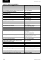
USE COPPER WIRES ONLY. CLEARANCE FROM COMBUSTIBLE SURFACE: UNIT IS 0 INCHES,
DUCT IS 0 INCHES. MAXIMUM INLET TEMPERATURE; 100^ F / MAXIMUM OUTLET
TEMPERATURE; 200^ F. EXTERNAL STATIC PRESSURE RANGE OF 0.25'' - 5.00'' WG. CONFORMS
TO UL STD 1995 AND CERTIFIED TO CSA STD C22.2 NO 236
(Skid 5 of 5)
(Skid 3 of 5)
(Skid 4 of 5)
(Skid 1 of 5)
(Skid 2 of 5)
(FS)(CC-HM)(XA-IC-XA-RF)(EE)(FR)
9800071
LD11728A
FIG. 3 – UNIT ID LABEL
Direction of Airflow
Order of Assembly
* See Table 1 for Segment Identification
LD11752A
FIG. 5 – SEGMENT ID BOX EXAMPLE
johnson controls
21
FORM 102.20-N1 (1109)
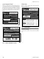
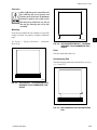
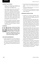
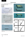
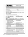
Loose Component ID Label
Filter ID Label
Each loose component has a label showing where it is
to be installed on the unit. The segment identification
box on the label will show the skid that it is installed
on. If the loose component goes on only one segment
on that skid the segment in the box will be bolded (see
Fig. 6).
Figure 7 shows a typical Filter Label with Filter
Segment and Filter List.
COM : 117817
MODEL #
XTO-108X120-JJRN046A
SERIAL # / DATE CODE
JOB IDENTIFICATION #
CHTM XT0085
08-179121-01-01
SEGMENT IDENTIFICATION
COM :
MODEL #
(XA-IC-XA-RF)
9550
XTO-096X144-HDNL046A
SERIAL # / DATE CODE
JOB IDENTIFICATION #
ANPM XT0004
05-162730-16-01
Filter
SEGMENT IDENTIFICATION
(EE)
SHS-RTU-5
JOB NAME
SKID OVERALL SIZE
St. Vrain 2005 Skyline CS
106 H x 192 W x 106 L
FLTR,CLNBL,AL,26.5W_27.5H_.88D
SKID OVERALL SIZE
116 H x 156 W x 76 L
026-32404-009
026-32404-010
Moisture Eliminator
026-41366-104
JOB NAME
Owens Corning BLDG-21
Filters
026-32406-001
026-32406-003
UNIT TAG
OA Moisture Eliminator
Qty 9
OA Moisture Eliminator installed on (EE) skid/segment.
LD11730
Spare Filters
026-32406-001
026-32406-003
026-32404-009
026-32404-010
FLTR,PERFPLT,30%EFF,12W_24H_2D
FLTR,PERFPLT,30%EFF,24W_24H_2D
Qty: 4
Qty: 16
FLTR,VCL_SH,12W_24H_12D,80-85%
FLTR,VCL_SH,24W_24H_12D,80-85%
Qty: 4
Qty: 16
FLTR,PERFPLT,30%EFF,12W_24H_2D
FLTR,PERFPLT,30%EFF,24W_24H_2D
FLTR,VCL_SH,12W_24H_12D,80-85%
FLTR,VCL_SH,24W_24H_12D,80-85%
Qty: 8
Qty: 32
Qty: 4
Qty: 16
FIG. 7 – filter LABELS
Bird Screen
COM : 117817
MODEL #
XTO-108X120-JJRN046A
SERIAL # / DATE CODE
JOB IDENTIFICATION #
CHTM XT0085
08-179121-01-01
SEGMENT IDENTIFICATION
Outside Air 386-60000-938 Hood - EE
Hood
1 of 6
UNIT TAG
AHU 9-10
LD13942
Direction of Airflow
The direction of airflow is always read from right to
left.
*Ship Loose*
UNIT TAG
AHU 9-10
JOB NAME
SKID OVERALL SIZE
Owens Corning BLDG-21
116 H x 180 W x 85 L
AHU 9-10
One of six hoods installed on (EE) skid/segment.
LD11751A
FIG. 6 – LOOSE COMPONENT ID LABELS
22
johnson controls
FORM 102.20-N1 (1109)
1.0 pre-installation
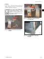
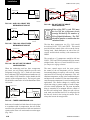
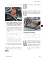
RECEIVING
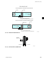
RIGGING OF INDOOR AND OUTDOOR UNITS
All units leaving the plant have been inspected to ensure
the shipment of quality products. All reasonable means
are utilized to properly package the air handling units.
Johnson Controls will NOT be responsible for any damage or loss of parts
in shipments or at the job site. Receiver is solely responsible for noting
Bill of Lading and filing freight claims
IMMEDIATLY. Refer to Shipping
Damage Claims Form 50.15-NM
available from Johnson Controls Sales
representative.
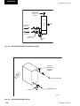
All lifting points must be used to avoid
personal injury or death and to avoid
damage to the equipment.
1
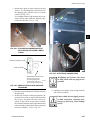
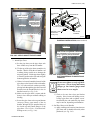
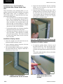
SHIPPED LOOSE DAMPERS. When
large units are ordered with MZ segments in rear discharge location (on
the end of the unit), the units will
ship with the top section (hot deck)
separated. In these cases, the complete multizone damper assembly (hot
deck and cold deck together) will ship
loose.
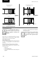
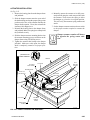
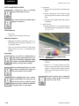
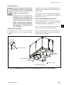
SPREADER BARS MUST BE WIDER THAN THE
UNIT WIDTH TO PREVENT DAMAGE TO THE
HOUSING & ROOF EDGE.
LD13769
FIG. 1-1 – RECOMMENDED LIFTING WITH FOUR LIFTING POINTS
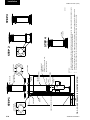
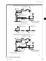
SPREADER BARS MUST BE
WIDER THAN THE UNIT WIDTH TO
PREVENT DAMAGE TO THE
HOUSING & ROOF EDGE.
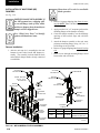
RIGGING INSTRUCTIONS
FOR LIFTING AIR HANDLERS WITH LIFTING LUGS, USE
SPREADER BARS AND CABLES AS INDICATED. DO NOT USE
A FORKLIFT. ALL LIFTING LUGS MUST BE USED TO AVOID
DAMAGE.
60°min.
LD13765B
FIG. 1-2 – RECOMMENDED LIFTING WITH MULTIPLE POINTS
johnson controls
1-1
Pre-installation
FORM 102.20-N1 (1109)
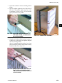
All lifting lugs must be used to avoid
damage to unit. If unit does not have
lifting lugs, use bottom corner connectors and intermediate raceway lifting
lugs. Do not use top corner connectors.
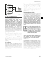
Off-Loading
Proper rigging and handling of the equipment is
mandatory during unloading and setting it into position
to retain warranty status.
Care must be taken to keep the unit in the upright
position during rigging and to prevent damage to the
air and watertight seams in the unit casing. Prevent
unnecessary jarring or rough handling.
For lifting air handling units with lifting lugs or corner
connectors; proper spreader bars and hoisting line
must be used when rigging to prevent damage to the
unit casing (see Fig. 1-1). When lifting long units a
special system must be used to insure a minimum 60°
angle between lifting lug and spreader bar/frame (see
Fig. 1-2 and Table 1-1). It is also mandatory that an
experienced and reliable rigger be selected to handle
unloading and final placement of the equipment. The
rigger must be advised that the unit contains internal
components and that it be handled in an upright
position. Care must be exercised to avoid twisting the
equipment structure.
Refer to the submittal for the section
weights.
TABLE 1-1 - SPACING REQUIREMENTS FOR
OFFLOADING LONG UNITS
UNIT HT.
MAX. LIFTING
LUG SPACING
MIN. LIFTING
STRAP LENGTH
≤ 72"
120"
120"
> 72"
192"
192"
Unit section weights are furnished on the job submittal.
Due to the variance in weight of each unit design, it is
not possible to list unit weights in this instruction. The
submittal must be referred to when selecting a crane
for rigging and figuring roof weight loads. Contact
your Johnson Controls Sales representative if you have
any questions regarding unit weights.
Crane And Spreader Bars
See Fig's 1-1 and 1-2.
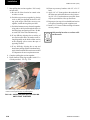
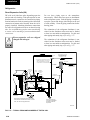
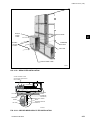
Fork Lift
Forklifts should not be used to off-load air handlers
except in special circumstances. If moving air handling
equipment with a fork lift or similar means becomes
necessary, always make sure the lifting forks are long
enough to reach from the fork truck to the opposite side
and slightly beyond. It is helpful to leave the shipping
blocks attached to the bottom of the equipment until
in its final location. There is no structural support
under the equipment except what is visible from the
perimeter.
Come-A-Longs or Power Pull
See Fig1-3 below
LD09613
FIG. 1-3 – TYPICAL COME-A-LONG TYPES
1-2
johnson controls
FORM 102.20-N1 (1109)
Shackles
Refer to Fig. 1-4 for proper lifting with hook and
shackle at corners. Refer to Fig. 1-5 for proper lifting
with hook and shackle at lifting lugs.
Figures 1-4 and 1-5 show YORK Solution unit without baserails. When
baserails are present, always use all
lifting lugs pre-mounted on baserails.
Do not lift by corners.
1
LD13768
FIG. 1-5 – P
ROPER LIFTING WITH SHACKLE
AT LIFTING LUG
LD13767
FIG. 1-4 – P
ROPER LIFTING WITH SHACKLE AT
CORNER
LD13766
FIG. 1-6 – R
ECOMMENDED LIFTING WITH
BASERAIL
johnson controls
1-3
Pre-installation
FORM 102.20-N1 (1109)
INSPECTION
STORAGE
Check For Damage
Short-Term Storage
Indoor Units:
Under no circumstances should outdoor storage be used
Receiver Responsibility
Receiver is solely responsible for noting freight bill and
filling freight claims IMMEDIATLY (see “Receiving”
in this section).
Visible damage should be noted on the signed and
dated bill of lading with a request that the carrier
inspect the damage within 72 HRS. of notification. The
shipping wrapper must be removed and replaced with
a tarp or similar protective covering. Any concealed
damaged reported after 15 days will compromise a
claim settlement. Inspection requests may be done
by telephone or in person, but should be confirmed in
writing. If assistance is needed with the claim process,
contact your Johnson Controls Sales representative.
Indoor Units
It is Johnson Controls intention that a shipping wrapper
be applied to unpainted indoor units for protection
from weather, road dirt, etc. during inland transit and
that the wrapper be removed at the time of delivery to
allow for a thorough inspection, both inside and out.
Outdoor Units
Outdoor units are not fully wrapped. Exposed openings
are covered for protection from weather, road dirt, etc.
during inland transit. A thorough inspection, both
inside and out, should be done at the time of delivery.
Checking for Non Mounted Parts
• Check the packing list for non-mounted ship
loose parts. (Check inside all segments.)
• Packing list will note how many and type of
parts.
• Shortages must be reported within 10 days after
receipt of order.
See Ship Loose Parts, Fig 2-8 thru 2-14.
1-4
Outdoor Units:
Be sure all shipping covers are reapplied after inspection, or tarps are
used during storage.
Short-term storage is considered six (6) months or less
from date of shipment. Storage maintenance during
this time is usually limited to the following.
• Rotate fans every four (4) weeks beginning upon
arrival to prevent moisture from damaging bearing.
• If the units are to be stored out-of-doors, prior to
installation, special care must be taken to cover
and protect the units from dust, rain, snow and
rodents. The units must be protected from constant exposure to rain and snow.
• Store on a firm, flat surface to prevent distortion.
Block the unit off the ground to protect components from water.
IAQ
Protect all parts and porous materials
from rain and other sources of moisture. Decontaminate or replace as
needed to ensure microbial growth is
not introduced to the air handler.
• The unit must also be protected from damage to
the exterior of the cabinet or coil connections by
construction vehicles and personnel.
johnson controls
FORM 102.20-N1 (1109)
Long-Term Storage
Long-term storage is considered any period beyond
six (6) months from date of shipment. If long-term
storage is anticipated, contact the Johnson Controls
Sales representative for the proper instructions and
requirements for long-term storage. It is mandatory
that a detailed record be maintained during this longterm period, such as, but not limited to: proper sealing
of the cabinet, rotation of the blowers and bearings,
and protection of all motors from moisture. Refer to
Form 50.20-NM3 “Long Term Storage Requirement Field Preparation” and Form 50.20-CL3 “Long Term
Storage Periodic Checklist and Logs”, copies of which
is included in this section.
Preventive Maintenance Prior to Long Term
Storage
The following precautions should be taken prior to
extended storage:
• Fan and motor bearings are to be greased per the
manufacturer’s specifications.
• Motors and sheaves must be protected from
free moisture or high humidity. This may be
accomplished by 1) spraying components with
an anti-rust solution (P/N 026-37707-000) or 2)
disconnecting the belts and wrapping the sheaves
and motor and sealing them with plastic. Insert a
desiccant to absorb moisture that may penetrate
the plastic protection.
• The fan motor windings should be megged at
this time and recorded for comparison prior to
placing in service.
• If the fan housing was supplied with a drain connection, this plug should be removed to prevent
moisture from accumulating in this portion of the
fan during storage.
johnson controls
Long-term storage is considered to be
any period beyond six (6) months from
date of shipment. If long-term storage
is anticipated, contact Johnson Controls Sales representative at time of
order entry for the proper instructions
and requirements for long-term storage. Refer to Form 50.20-NM3.
Periodic Fan Check
On a monthly basis, the fan and motor should be
rotated several times to replenish the bearing surfaces
with fresh grease.
The fan impeller should be left at approximately 180
degrees from that of the previous month to prevent the
belts from taking a set position.
It will be the responsibility of the customer to submit a monthly log sheet
(MS577) showing the condition of the
unit and noting any discrepancies. A
copy of the log sheet should be sent
to the Johnson Controls Office, attn.:
Sales Representative.
Failure to perform the long-term storage requirements will void the warranty.
1-5
1
Pre-installation
FORM 102.20-N1 (1109)
FIG. 1-7 – L
ONG-TERM STORAGE REQUIREMENT - FIELD PREPARATION, FORM 50.23-NM3
1-6
johnson controls
FORM 102.20-N1 (1109)
1
FIG. 1-8 – L
ONG-TERM STORAGE PERIODIC CHECKLIST AND LOGS, FORM 50.23-CL3
johnson controls
1-7
FORM 102.20-N1 (1109)
THIS PAGE INTENTIONALLY LEFT BLANK
1-8
johnson controls
FORM 102.20-N1 (1109)
2.0 INSTALLATION
Do not weld or use torches on the exterior or interior of the unit housing.
The housing contains polyurethane
insulation, which under combustion
will produce harmful, toxic gases resulting in personal injury or death.
Never use silicone caulk/sealant or
caulk/sealant containing silicone in or
on any air handling equipment. [Only
exception is when provided (high temperature) with gas heat venting].
SITE PREPARATION
This instruction is written to provide
general information. The product
line allows many variations and the
installer is fully responsible for adjusting his actions as needed. If any
questions regarding the content of
this manual, or if any information is
not covered, contact local Johnson
Controls Service.
Outdoor Units (Site Prep)
Location of unit(s) should be away from building
flue stacks or exhaust ventilators to prevent possible
introduction of contaminated air through the outside
air intakes (see Fig. 2-1 for service clearances).
Allow sufficient space around the unit
for removing the access panels and
various parts of the unit. A minimum
clearance equal to the width of the unit
must be provided on one side of the
unit for removing the coil or fan assembly. Add dimension of pipe chase,
air hoods, ducts, control/electrical
panels, etc. to minimum clearances.
Allow additional clearance as required
by local and national codes. Consider
Coil Access Panel for coil removal on
outdoor units.
Surface must be level on all installations.
If your unit has HEPA filters the filter frames, filter bulkheads and filter
segment panels are factory sealed
and must remain sealed for NO air
bypass.
MIN. CLEARANCE DIMENSIONS
A Fan Section
36"
B Coil Section
H
36"
36"
A
B
C
D
E
F
G
UNIT WIDTH
C Face and Bypass Damper Section
D Filter Section - Door should open 180°
E
Inlet Section
F Rain Hood (add to unit width or length)
G Pipe Chase Enclosure (add to unit width)
H Coil Access Panel on Outdoor Unit (allow clearance = to unit width)
FIG. 2-1 – MINIMUM SERVICE CLEARANCES
LD6328-4
johnson controls
2-1
2
Installation
FORM 102.20-N1 (1109)
Mounting
Curb
Units must be installed in such a manner as to provide
enough elevation for properly designed condensate
traps (see Section 2 “Drain - Condensate Drain
Trap”).
The curb, which supports the unit, will be shipped
unassembled. It will be necessary to assemble the curb
parts on the job site. Assembly drawing and a hardware
package are shipped with each curb package. It is
important the curb be installed square. If applicable,
ensure pitch orientation is correct.
Installation Site: Area of roof on which
curb is to be installed must be structurally adequate to support the combined
weight of curb, unit and system fluids.
With these combined weights in place,
the resting surface for the unit MUST
be flat and level.
Concrete pads often are not as flat
as they should be. Shimming and/or
grouting may be necessary. Whether
under the unit base or under the curb,
this is to ensure the unit base is on a
perfectly flat plane.
This “Curb Assembly and Installation Instruction” is
typical. Use it in conjunction with the specific drawing
supplied with each curb.
Should there be any questions as to
the number of pieces of curb parts or
assembling of the curb, notify Johnson
Controls immediately.
Curb, nailer, and gasket are supplied.
All other parts such as wood or fiber
cant strips, roofing felts, roofing material, caulking and curb-to-roof fasteners are to be field supplied.
Be sure the supporting structures will
not obstruct the duct, piping or wiring
connections.
2-2
johnson controls
FORM 102.20-N1 (1109)
Curb Assembly and Installation Instructions
See Fig. 2-2
1. Unpack shipping package, layout pieces and
parts according to the exploded views and check
against Bill of Materials.
2. Layout all channel pieces as shown. Make certain
that all channel tabs are located on inside of mating channel
Make certain that all curb walls accessories and flanges, which may
have been distorted in handling, are
straightened before assembly.
3. Attach curb walls together to form rectangular
perimeter as shown, leaving bolts loose.
After the curb is set in place, ensure
proper consideration has been given
to the air duct openings through the
roof.
When unit is shipped in sections, the
curb gasket is to be replaced with caulk
provided by contractor.
5. After verifying curb is square and level, tighten
all bolts and then anchor as appropriate.
If bolts are tightened after anchoring,
curb will be pulled, twisted and torqued
out of square.
6. Pipe Chase Curb Assembly - once curb is square
and level mark the exact location for the pipe
chase curb. Drill and assemble.
Pipe Chase Curb Location:
Unit submittal drawing package has
a Johnson Controls curb drawing
showing dimensions of curb and pipe
chase.
7. The curb should be insulated and roofed as required. Refer to SMACNA for counter flash.
4. The curb installation drawing (see Fig. 2-2)
shows a gasket that is mounted between the curb
and the unit. This gasket is shipped with the curb
parts. Install the curb gasket before setting the
unit on the curb. The gasket forms an air seal
between the unit and the curb and serves as a
dampener, preventing metal-to-metal contact
between the unit and curb. However, the gasket
should not be used as a vibration isolator where
the prevention of noise and vibration transmission into the building is critical.
johnson controls
Steel Frame
When a steel frame is used to support the unit, it must
be level, flat without uneven steel frame joints, and
support the unit around the full perimeter. As a general
rule, cross members should be placed every 96" in
addition to every shipping split.
Indoor Units (Site Prep)
Concrete pads often are not as flat
as they should be. Shimming and/or
grouting may be necessary. This is to
ensure the unit base is on a perfectly
flat plane.
2-3
2
Installation
FORM 102.20-N1 (1109)
CURB SUPPORTS
as required
D
UNIT WALL
RIGHT HAND
PIPE CHASE
A
UNIT RACEWAY
B
B
C
1-7/8"
CURB REST
Note 1
1-7/8"
CURB GASKET
2" x 4" NAILER
1-1/2"
"A"
Note 1
UNIT
ROOF
CURB
Curb for Pipe Chase
LEFT HAND
PIPE CHASE
"A"
2"
2"
PIPE CHASE SECTION VIEW
SECTION "A-A"
Screw flange of pipe chase
curb to unit roof curb 2" x 4"
nailer.
CURB CALCULATION FOR OUTSIDE DIMENSIONS
A = Total unit length from YORKworks minus 0.875"
B = Pipe chase location distance from unit discharge end.
Pipe chase Mtg. holes will not be included on the
pipe chase curb. Mtg. will be field located.
C = Pipe chase length minus 0.875"
D = Total unit width from YORKworks minus 0.875"
Screw flange of pipe chase
curb to unit roof curb.
DETAIL B
PIPE CHASE CURB CONNECTION
TO UNIT CURB
WALL PANEL
WALL PANEL
STANDARD
RACEWAY
STANDARD
RACEWAY
1.25"
CURB GASKET
0.438"
TYP.
CURB REST
2" x 4" NAILER NOMINAL
1.50"
3.5"
1.5"
1.875"
TYP.
Note 1
2.00"
TYP.
Note 2
CURB GASKET
CURB REST
2" x 4" NAILER
NOMINAL
ROOF CURB
TYPICAL CURB SECTION
FOR UNITS W/O BASE RAIL
STANDARD
BASE RAIL
Note 1
ROOF CURB
DIMENSIONS
Notes:
1. Curbs available in 14", 18", 22", 26", 30" & 34" heights
2. Outdoor Base Rails are available in 6", 8" & 10" heights.
Contractor is responsible for providing ductwork to include Base Rail height.
TYPICAL CURB SECTION FOR
UNITS WITH BASE RAIL
3. Curb material is galvanized steel, unpainted, and may vary in gage
based on the unit load and the Qty. of cross bracing provided.
4. If curb space used as plenum, Seal all joints and seams with suitable sealer
such as urethane caulk (YORK P/N 013-02966-011)
LD09616G
FIG. 2-2 – TYPICAL CURB ASSEMBLY
2-4
johnson controls
FORM 102.20-N1 (1109)
Clearance
Allow sufficient space around the unit
for removing the access panels and
various parts of the unit. A minimum
clearance equal to the width of the
unit must be provided on one side of
the unit for removing the coil or fan
assembly.
Mounting
Units must be installed in such a manner as to provide
enough elevation for properly designed condensate
traps.
See Section 2 “Piping Connections - Condensate
Drain Trap.”
0
2
LD05373
FIG. 2-4 – NO HOUSEKEEPING PAD – BASERAIL
REQUIRED TO ACCOMMODATE TRAP
HEIGHT
Floor
The floor must be flat and level.
Housekeeping Pad
The housekeeping pad must be flat and level (see Fig's
2-3, 2-4 and 2-5).
LD05372
FIG. 2-3 – NO BASERAIL – HOUSEKEEPING PAD
REQUIRED TO ACCOMMODATE TRAP
HEIGHT
LD05374
FIG. 2-5 – W
ITH BASERAIL AND HOUSEKEEPING
PAD
johnson controls
2-5
Installation
FORM 102.20-N1 (1109)
STRUCTURE PERPENDICULAR TO AIRFLOW
STRUCTURE PARALLEL TO AIRFLOW
(Units under 5 ft. wide)
FAN SECTION
BDW COOLING
BDW COOLING
(Units over 5 ft. wide)
FS
AIR FLOW
AIR FLOW
PLAN VIEW
PLAN VIEW
MC
RF
CC
MB
FAN SECTION
RF
MB
FS
LD09619a
ELEVATION VIEW
ELEVATION VIEW
FIG. 2-6 – CEILING SUSPENDED UNIT
Ceiling Suspended Units
It is recommended that support is
structurally engineered to prevent
flexing, sagging or twisting of air
handlers.
• Under heavy components like fans, attenuators,
and heating segment.
Do not obstruct door operation, filter
access, piping, electrical or control
connections with suspension members.
Refer to Fig. 2-6 “Ceiling Suspended Unit” for proper
support of unit in the direction of airflow and/or
perpendicular to the direction of airflow.
General Requirements
Johnson Controls recommends that ceiling suspension
of units be accomplished in the field with the
following:
Structure Positioned Perpendicular to Airflow
The units must be supported (at a minimum) in the
following locations:
• Both ends.
• At each shipping split.
• Upstream and downstream of each cooling coil
segment.
2-6
johnson controls
FORM 102.20-N1 (1109)
Structure Positioned In the Direction of Airflow
The unit base must be supported continuously, on both
sides of the unit.
UNIT INSTALLATION
See Fig. 2-7.
•
•
•
•
Tools Needed
•
•
•
•
•
•
•
Drill with adjustable torque.
No. 3 Phillips bit.
Allen wrench set.
Nut setter - Sizes 1/4", 5/16", 3/8" and 9/16" or
socket set.
Wire cutters.
Power pulls or come-a-longs.
Slings.
Pry bar.
Drift pins and awls.
Common hand tools.
Caulking gun.
Material not provided by Johnson
Controls. When unit is shipped in
sections, the gasket provided with the
curb is to be replaced with caulk provided by contractor. Gaskets on curbs
can pose a problem when sliding sections together for the final connection
of each shipping split.
LD09613
FIG. 2-7 – TOOLS TYPICALLY USED FOR
ASSEMBLY OF SHIPPING SPLITS
johnson controls
2-7
2
Installation
FORM 102.20-N1 (1109)
Ship Loose Parts
Look for label “Installation Instructions and Ship
Loose Items Inside”. This label is normally located on
the access door of the first fan section in the air stream.
Only the parts listed in this section which are required
for your unit are included.
3/8" x 3/4" Button
Head Screw
3/16" Allen
Wrench
3/8" Nut
Baserail Lifting Lugs Assembled
1/2" x 4" Bolt
Size = 3/16"
Allen Wrench
3/8" Flat
Washer
3/8" Lock Washer
Bracket p/n 086-11146-001
LD11029A
FIG. 2-8 – S
ECOND TIER TIE-DOWN FASTENER PACK
P/n 386-03419-000 (4 each per pack)
1/2" Nut
1/2" Lock
Washer
1/2" Flat
Washer
LD11032A
FIG. 2-10 – B
ASERAIL SHIPPING SPLIT FASTENER PACK
P/n 386-03417-000 (4 each per pack)
Raceway Lifting Lug (at shipping split)
3/8" Nut
3/8" x 1-1/2" Bolt
1/2" x 5-1/2"
Hex Cap
Screw (2)
Raceway Lifting Lugs
(assembled)
3/8" Flat
Washer
3/8" Lock
Washer
FIG. 2-9 – B
OTTOM RACEWAY SHIPPING
SPLIT FASTENER PACK
P/n 386-03418-000 (4 each per pack)
2-8
1/2" Hex
Nut
Lock Washer (2)
.56" ID x 1.38"
OD Flat
Washer (2)
LD13349
LD11030A
FIG. 2-11 – TOP RACEWAY SPLIT FASTENER PACK
P/n 386-04747-000 (2 each per pack)
johnson controls
FORM 102.20-N1 (1109)
Floor, Wall & Indoor Top Seam Cap
Roof Seam Cap (Outdoor)
SEAM CAP
• 1/4" x 2" Neoprene Gasket, P/N 028-15954-010
• 1/4"-14 x 1" Phillips Pan Head Tek Screw, P/N 021-19560-000
• 1/4"-14 x 1" Hex Head w/ Washer & Gasket Tek Screw
2
P/N 021-30530-052 for Outdoor Wall.
Apply 2" Gasket
& Caulk
•
•
ROOF SEAM CAP
1/4" x 2" Neoprene Gasket, P/N 028-15954-010
1/4"-14 x 1" Hex Head w/ Washer & Gasket Tek Screw
P/N 021-30530-052 for Outdoor Roof.
PIPE CHASE TRIM ANGLE
• 1/4"-14 x 1" Hex Head w/ Washer & Gasket Tek Screw
P/N 021-30530-052
• 1/4" x 2" Neoprene Gasket, P/N 028-15954-010
Apply 2" Gasket
& Caulk
Apply Butyl
PIPE CHASE
• 1/4" x 2" Neoprene Gasket, P/N 028-15954-010
• 1/4"-14 x 1" Hex Head w/ Washer & Gasket Tek Screw
P/N 021-30530-052
Apply Caulk
Apply Caulk
PIPE CHASE BASERAIL COVER
P/N 086-23998-001
HOOD
• 1/4"-14 x 1" Hex Head w/ Washer & Gasket Tek Screw
• 3/16" x 3/4" Butyl Tape
LD13770A
FIG. 2-12 – PIPE CHASE, HOODS & SEAM CAPS
johnson controls
2-9
Installation
FORM 102.20-N1 (1109)
CORNER CONNECTOR HOLE PLUG
P/N 021-19568-000
DAMPER SHAFT EXTENSION KIT
P/N 026-33715-002
HUMIDIFIERS
Optional Steam humidifiers, when selected are
provided with dispersion equipment factory mounted
inside the air handling unit. The steam injection or
generating equipment, metering devices and sundries
are shipped loose.
CONTAINMENT
BAND
CLOSURE
BAND
FLUE CAP
42"L VSI PIPE
(not insulated)
STORM COLLAR
UV
UV
LIGHT
LIGHT
TUBE
TUBE
GAS FURNACE FUEL VENTING PARTS
UV LIGHT TUBES to be installed by contractor.
DO NOT touch UV Lamps (tubes)
with bare hands or leather gloves as
oils will damage the tubes. Use clean
cotton rags, clean jersey or latex gloves
to handle the lamps (tubes).
LD13788
FIG. 2-13 – Miscellaneous parts for Options
2-10
johnson controls
FORM 102.20-N1 (1109)
1/4” X 3-1/2” x 3-1/2” SHIPPING SPLIT
CORNER GASKET
P/N 028-11883-010
(Outdoor Only)
POLYURETHANE CAULK
P/N 013-02966-011 GREY,
P/N 013-03317-040 CHAMPAGNE
Never
useuse
silicone
Never
siliconecaulk/sealcaulk/sealant ant
or caulk/sealant
containing
or caulk/sealant
containsilicone
in
or
on
any
air
handling
ing silicone in or on any air
equipment.
Only exception
handling equipment.
[Onlyis
when
provided
(high
temperature)
exception is when provided
with(high
gas heat
venting. with gas
temperature)
heat venting]
2
12 OZ. TOUCH-UP SPRAY
P/N 013-03322-000
1/4” X 3/4” X 35' NEOPRENE
GRAY GASKET
P/N 028-11873-010
1/4” X 2” X 25' NEOPRENE GASKET
P/N 028-15954-010
3/16” X 3/4” X 40' BUTYL TAPE
P/N 013E-03327-010
1/4”-14 X 1”
PHILLIPS PAN HEAD
SELF DRILLING SCREW
P/N 021-19560-000
SPARE FAN BELT
(Attached to Fan)
1/4”-14 X 1”
HEX HEAD
SELF DRILLING SCREW
W/ EDPM WASHER
P/N 021-30530-052
LD13771
FIG. 2-14 – HARDWARE, GASKETING, CAULK, PAINT AND TAPE
johnson controls
2-11
Installation
FORM 102.20-N1 (1109)
TOP SPLIT
BOTTOM SPLIT - RACEWAY,
BASERAIL W/ LUG
BOTTOM SPLIT - RACEWAY
W/ LUG
CURB REST
BOTTOM SPLIT - RACEWAY,
BASERAIL W/ LUG & CURB
REST
BOTTOM SPLIT - RACEWAY
W/ LUG AND CURB REST
LD09620C
FIG. 2-15 – SHIPPING SPLIT EXAMPLES
WELDED CHANNEL FILLER
BASE CHANNEL
REMOVABLE LIFITING LUGS
Remove lifting lugs before
assembling shipping splits.
Retain bolts,etc. and use to
secure assembled shipping split.
BASE CHANNEL
3/4" GR5 HEX BOLT
(use from Lifting Lug)
3/4" ZINC HEX NUT
(use from Lifting Lug)
(no flat or lock washers required)
LD14263
FIG. 2-16 – SHIPPING SPLIT EXAMPLES FOR EXPANDED CABINET
2-12
johnson controls
FORM 102.20-N1 (1109)
Assembly of Outdoor Unit
See rigging suggestions and details
in Section 1. Failure to follow these
guidelines may result in damage to
equipment.
Do not damage factory installed pipe
chase, electrical cabinet, hoods, pipe
stubs, door handles or roof overhang.
See “Ship Loose Parts” to identify
gaskets and hardware items.
Installing Single Piece Outdoor Unit
1. Units should not be moved on a roof surface
but should be lifted from the ground onto
the curb or support framework. Remove
the wood shipping material from bottom of
unit.
The curb gasket, which is provided,
must be installed before the unit is
lowered onto the curb. The gasket is
shipped with the curb package.
2. SEAL (to curbing): When setting the unit onto
the curb, the installer should ensure that a sealing
gasket is positioned between the unit and curb
to provide a continuous airtight and watertight
connection.
3. Installation should be in accordance with local
code requirements.
When installing on steel or slab, eliminate seal unless specified.
Installing Multiple Piece Outdoor Unit
See Fig. 2-15 and 2-16 for Shipping Split Examples.
If applicable, remove metal bracket
screwed to the cross channel and wood
shipping blocks before assembling
shipping splits.
When unit is provided with shipping
splits, use construction grade caulk
(not provided) in place of curb top
gasket. Apply the caulk on top of curb
just before each section is placed on
the curb. Apply the caulk with a 1/2"
diameter bead to assure seal after sections are pulled together. Positive seal
must be achieved. Disregard this note
if shipping splits are assembled prior
to placing the unit on curb.
If assembly is done prior to setting
unit sections on a curb, be sure to
have units on a flat surface during
the assembly process. Do not remove
shipping blocks from under unit until
assembled unit is ready to be lifted
and placed.
Make sure top of curb is flat and shims
added where/if needed to ensure curb
will remain flat.
1. Before placing sections on the curb:
a) Verify the correct sections and orientation of
each section.
b) Remove cross brace(s) (shipping supports)
from each section’s shipping split.
c) Remove plastic shipping covers and their
supports.
d) Remove screws from curb rest to release
wood shipping blocks. Leave blocks under
unit sections until lifted. Be sure that no
debris clings to the bottom of each section
when lifted for placement.
johnson controls
2-13
2
Installation
FORM 102.20-N1 (1109)
e) Make sure all wiring and/or control tubing
connection pig tails are secured out of the
path of the shipping split mating surfaces to
prevent damage.
f) Apply 3.5" x 3.5" separate gasket squares,
placing one square at each corner of the face
of one section. Apply 1/4" x 2" foam gasket
to face perimeter from 3.5" square to 3.5"
square. Apply this gasket 1/4" from outside
edge of mating surface (nearest to exterior of
air handler). This is to allow for a 1/4" bead
of caulk. Refer to Fig. 2-17.
Butt joints to raceway gasket.
Caulked at joints.
6. Place the next section on the curb about 4" from
the section already placed.
7. At this time feed the electrical and control connections from section to section and ensure that
they will be accessible after the sections are
joined. Assemble the electrical connectors and/
or pneumatic tubes each according to their labels.
Do this before joining sections if access will be
a problem later. Refer to Fig. 2-18.
Connectors
0.25
thk
0.25 thk
neoprene at
at
neoprene
raceway split.
split.
raceway
LD13773A
The gasket application should provide a continuous seal from
side to side and the top of the unit roof to the bottom of the unit
base where it meets the curb.
LD13372A
FIG. 2-17 – APPLYING GASKET
g) Apply a ½" thick bead of caulk (not
provided), to curb top surface only where
the first section will be placed.
2. Place the first section on the curb while positioning it so that the overhanging curb rest is spaced
evenly from the curb on each side and end.
3. After the first section is placed in position, anchor
or block it before setting the next section.
4. Attach power pulls or come-a-longs to the first
section. Use lifting lugs on the baserail (not at
the shipping split) or holes in the two outside
corners.
5. Apply a ½" thick bead of caulk to curb top surface
only where the next section will be placed, plus
about 4".
2-14
LD13374
FIG. 2-18 – ELECTRICAL CONNECTIONS
All lighting and 3-phase wires must
be hard wired when no plug-ins are
provided.
johnson controls
FORM 102.20-N1 (1109)
After wiring connections are made
and before proceeding with assembly,
the top shipping split angle will need
to be removed and repositioned (see
Fig. 2-19).
Ensure chain does not apply pressure
to drain connection. Improper positioning of chain may cause damage
to unit.
9. Start pulling this section toward the first section.
Pull evenly on both sides.
a) Be sure all of the electrical or control wires
or tubes are clear.
b) Guide the top raceways together by placing
rods or drift pins through the holes in the top
guide angles. When the raceways are close
enough, install the long bolts provided.
c) Guide the bottom raceways together using
rods or drift pins through the bolt holes in
the lifting lugs on opposite sections. Do this
on each side of the unit simultaneously.
d) If any difficulty aligning due to racking of
one section or the other, use another come-along diagonally on the inside of that section,
at or close to the shipping split. Straps may
be used across the unit roof.
Remove Shipping
Remove
ShippingSplit
SplitAngle
Angle
after
completion of
ofwiring
wiringand
and
after completion
tubing placement
placement and
and
tubing
reposition before
before proceeding
proceeding
reposition
with
assembly of
shipping
with assembly
of shipping
splits.
splits.
e) If any difficulty due to top and bottom not
pulling together evenly or simultaneously,
the curb is probably not installed flat. Apply
shims under the curb or roof decking to
compensate for irregularities of the roof
deck.
10.Complete pulling the sections together.
LD14097
FIG. 2-19 – R
EMOVE AND REPOSITION SHIPPING
SPLIT ANGLE
8. Attach the power pulls or come-a-longs to the far
end of the next section.
johnson controls
Use come-a-longs to pull the sections
together. The bolts are to hold the
sections tight after they are pulled
together.
11.Fasten bottom lifting lugs together using 1/2" x
4" bolts provided.
12.Fasten top raceway bracket using 1/2" x 5-1/2"
bolts.
2-15
2
Installation
FORM 102.20-N1 (1109)
LD13775
LD13777
LD13776
LD13778
FIG. 2-20 – BRINGING SECTIONS TOGETHER
13.Apply a 1/4" bead of caulking to the exterior
of the seam. Trowel the bead level with the air
handler exterior. This is to be done on roof and
both sides (see Fig. 2-20).
14.Apply 1/4" bead of caulking to the seam inside
the unit on the floor.
15.Apply 1/4" x 2" foam gasket to the underside of
the seam caps and install them over the joints
using 1/4"-14 x 1" hex head screws provided.
Painted seam caps are applied over the joints on
the sides and roof of the exterior and galvanized
seam caps are applied on the floor of the interior
only.
2-16
If a roof seam cap has a tab on one
end only, the end without the tab goes
above the pipe chase location.
16.Repeat this procedure for each additional section
to be placed in making up the complete unit.
17.Install 1-1/2" Corner Connector Plugs on bottom
raceway corners.
Only needed on units or sections without baserails.
johnson controls
FORM 102.20-N1 (1109)
Assembly of Indoor Unit
See rigging suggestions and details
in Section 1. Failure to follow these
guidelines may result in damage to
equipment.
Do not damage factory installed pipe
chase, electrical cabinet, hoods, pipe
stubs, door handles or roof overhang.
d) Make sure all wiring and/or control tubing
connection pig tails are secured out of the
path of the shipping split mating surfaces to
prevent damage.
e) Apply 1/4" x 2" neoprene gasket material
TO ONE SIDE ONLY of each shipping
split. Be sure the entire perimeter is covered
with gasket material, including the foamed
corners. Any void, depression or protrusion
will allow air or water leakage. Gasket must
be continuous through the corners. Make any
splices on a straight run. Refer to Fig. 2-21
and 2-22.
See “Ship Loose Parts” to identify
gaskets and hardware items.
2
If the unit or unit sections are too
large to fit through an opening, contact
the local Johnson Controls office for
assistance. Technical instruction is
available for Disassembly and Reassembly.
LD13779
Installing Multiple Piece Indoor Unit
See Fig. 2-15 and 2-16 for Shipping Split Examples.
FIG. 2-21 – APPLYING GASKET TO SHIPPING
SPLIT
If applicable, remove metal tab screwed
to the cross channel and wood shipping blocks before assembling shipping splits.
Panel
Flange
If assembly is done prior to placing
unit sections, be sure to have sections
on a flat surface during the assembly
process.
1. Before placing sections:
a) Verify the correct sections and orientation of
each section.
b) Remove cross brace(s) (shipping supports)
from each section’s shipping split.
c) Remove plastic shipping covers and their
supports.
johnson controls
Connectors out of
the way.
Door Frame
Flange
1/4” x 3/4”
Gasket Only
used when a
door frame is at
a shipping split.
LD13780A
FIG. 2-22 – APPLYING GASKET TO DOOR FRAME
WHEN AT SHIPPING SPLIT
f) For expanded cabinet with end channel
shipping split see fig. 2-23
2-17
Installation
FORM 102.20-N1 (1109)
HEAT WHEEL (ER) SEGMENT
END SPLIT MOUNTING BRACKET
SECURE TOGETHER USING 3/8" X 3/4"
BOLT, LOCK WASHER & HEX NUT.
REMOVE SHIPPING
BRACKETS
LD14262
FIG. 2-23 – ASSEMBLY OF END CHANNEL SHIPPING SPLIT (EXPANDED CABINET)
2. Place the first section in its final position and
anchor or block it before placing the next section
(see Fig. 2-25).
After wiring connections are made
and before proceeding with assembly,
the top shipping split angle will need
to be removed and repositioned (see
Fig. 2-24).
Remove Shipping
Remove
ShippingSplit
SplitAngle
Angle
after completion
completion of
ofwiring
wiringand
and
after
tubing placement
placement and
and
tubing
reposition before
before proceeding
proceeding
reposition
with
assembly of
shipping
with assembly
of shipping
splits.
splits.
LD14097
FIG. 2-24 – R
EMOVE AND REPOSITION SHIPPING
SPLIT ANGLE
2-18
johnson controls
FORM 102.20-N1 (1109)
3. Attach power pulls or come-a-longs to the first
section. Use the lifting lugs on baserail (not at
the shipping split) or holes in the two outside
corners (see Fig. 2-25).
For expanded cabinet with structural steel base
remove lifting lugs within the shipping split.
retain bolts and. nuts (see Fig. 2-26).
Connectors
2
LD13773A
LD13782
FIG. 2-25 – P
lacing and anchoring first
section and attaching come-alongs
WELDED CHANNEL FILLER
BASE CHANNEL
LD13374
FIG. 2-27 – ELECTRICAL CONNECTIONS
REMOVABLE LIFITING LUGS
Remove lifting lugs before
assembling shipping splits.
LD14265
Retain bolts,etc. and use to
secure assembled shipping split.
All lighting and 3-phase wires must
be hard wired when no plug-ins are
provided.
FIG. 2-26 – R
EMOVE LIFTING LUGS AND SAVE
HARDWARE
4. Place the next section about 8" from the section(s)
already placed.
5. At this time feed the electrical and control connections from section to section and ensure that
they will be accessible after the sections are
joined. If any will not be accessible, assemble
the electrical connectors and/or pneumatic tubes
each according to their labels before joining of
sections is complete. Refer to Fig. 2-27.
johnson controls
6. Attach the power pulls or come-a-longs to the far
end of the next section.
Ensure chain does not apply pressure
to drain connection. Improper positioning of chain may cause damage
to unit.
2-19
Installation
FORM 102.20-N1 (1109)
7. Start pulling the sections together. Pull evenly
on both sides.
a) Be sure all of the electrical or control wires
or tubes are clear.
b) Guide the top raceways together by placing
rods or drift pins through the holes in the
top guide angles. When the raceways are
together, install the long bolts provided.
c) Guide the bottom raceway/baserails together
using rods or drift pins through the holes in
the lifting lugs on opposing sections. Do this
on each side of the unit simultaneously.
d) If any difficulty aligning due to racking of
one section or the other, use another come-along diagonally on the inside of that section
at the shipping split or across the tops of
opposing sections..
10.Fasten top raceway brackets with 1/2" x 5-1/2"
bolts.
11.Apply 1/4" x 2" foam gasket to the underside of
the seam caps and install them over the joints using 1/4"-14 x 1" hex head screws provided. Seam
caps are provided for sides, top and floors.
12.Repeat previous steps for each additional section
to be placed in making up the complete unit.
13.Install 1-1/2" Corner Connector Plugs in bottom
raceway corners.
Only needed on units or sections without baserails.
e) If any difficulty aligning due to top and
bottom not pulling together simultaneously,
apply shims under the unit sections as needed
to compensate for uneven placement area.
8. Complete pulling the sections together.
9. Fasten bottom, lifting lugs together with 1/2" x
4" bolts provided. See Fig. 2-28.
LD13781
Use come-a-longs to pull the sections together. The bolts are to
hold the sections tight after they are pulled together.
FIG. 2-28 – installing bolts after pulling
units tight together
2-20
johnson controls
FORM 102.20-N1 (1109)
These brackets are used to secure the top segment to
the bottom segment. After final alignment, bolt the
two brackets with hardware supplied.
1. Before placing top tier:
a) Verify the correct orientation of top and
bottom tier.
b) Remove cross brace(s) (shipping supports)
from top tier.
c) Remove plastic shipping covers and their
supports.
d) Make sure all wiring and/or control tubing
connection pigtails are secured out of the
path of the mating surfaces to prevent
damage during rigging.
LD09624
FIG. 2-29 – TIERED UNIT
See complete rigging instructions explained in detail in Section 1.
See “Ship Loose Parts” in this section
of the Manual to identify gaskets and
hardware items.
A Tiered Unit may not be factory assembled. Field
assembled units are shipped with the top-tier segment
skidded. This top-tier segment is equipped with
brackets bolted to the bottom raceway (see Fig. 2-30).
The bottom-tier segment is equipped with brackets
bolted to the top raceway.
Size = 3/16"
Allen Wrench
TOP TIER
PLACE SECOND LAYER OF GASKET OVER FIRST LAYER
AND OVER RACEWAYS
TOP LEFT
RACEWAY
Installation of Tiered Unit
3/16" Allen
Wrench
e) Ensure 1/4" x 2" neoprene gasket properly
installed on bottom tier. If the top tier is
shorter in direction of airflow than the bottom
tier, apply gasket material on the top panel
of the bottom tier from raceway to raceway
but not on top of raceways (see Fig. 2-31).
3/8" x 3/4" Button
Head Screw
TOP RIGHT
RACEWAY
PLACE FIRST LAYER OF GASKET FROM RACEWAY TO
RACEWAY
BOTTOM TIER
LD09690
FIG. 2-31 – APPLY GASKETS TO TOP PANEL
BOTTOM TIER
f) Apply second layer of 1/4" x 2" gasket over top of
that applied in step (e) but include the raceways.
Steps (e) and (f) are necessary because the top
panel of the bottom tier is slightly recessed below
the height of its raceways.
g) If top tier has shipping splits, refer to “Installing
Multiple Piece Indoor Unit” for correct assembly
procedure.
3/8" Nut
3/8" Flat
Washer
TOP PANEL
LD09625
3/8" Lock Washer
LD11029A
FIG. 2-30 – TIERED UNIT SECURED WITH BRACKETS
johnson controls
2-21
2
Installation
FORM 102.20-N1 (1109)
Be sure all of the electrical or control
wires or tubes in both tiers are clear.
7. Lower the top tier onto bottom tier so that mounting brackets mate. Guide brackets together using
rods or drift pins through the bolt holes (see Fig.
2-32).
2. Install (4) shackles, one in each bottom corner
connector or raceway lifting lug.
3. Fasten sling/chain to shackles.
4. Fasten other end of sling/chain to spreader bar
(as needed).
5. Lift top tier assembly with crane or overhead
lift.
6. At this time feed the electrical and control connections from top tier to bottom tier and ensure
that they will be accessible after the sections are
joined. If any will not be accessible, assemble
the electrical connectors and/or pneumatic tubes
each according to their labels before joining the
top and bottom tier.
LD09626
FIG. 2-32 – GUIDING BRACKETS TOGETHER
8. Carefully place each section of the top tier without disturbing the gaskets on the bottom tier.
9. Secure the top tier to bottom tier with 3/8" x .75"
Allen head bolts.
10.Install 1-1/2" Corner Connector Plugs in bottom
raceway corners.
Only needed on units or sections without baserail
2-22
johnson controls
FORM 102.20-N1 (1109)
See “Ship Loose Parts” to identify
gaskets and hardware items.
5. Apply 1/4" x 2" neoprene gasket to all raceway
mating surfaces of one mating section. Include
two gaskets side by side on intermediate raceway
surfaces (large units).
6. Ensure that the sections are not racked and will
line up properly.
Assembly of End Channel Shipping Split
The assembly is the same regardless of
what sections are being connected together. The vertical Energy Recovery
Wheel shown in Fig. 2-33 is a common
example
Prior to pulling sections together:
1. Remove baserail support plate (large units).
2. Remove shipping brackets in corners.
3. Remove screws in raceway corners at ends of all
segments joining together (as shown in Detail A
of Fig. 2-33).
4. Clean the metal surface where gasket is to be
applied with mineral spirits or rubbing alcohol.
Attach sections as follows:
1. Make sure assembly surface is clean and level
to allow the sections to slide freely. If surface
is irregular, use metal shims under sections as
necessary to align mating surfaces.
2. Pull sections together using a come along, drawing the base together.
3. Attach the sides of the sections. Beginning at the
bottom of the sections secure the end channel assembly brackets together using 3/8" x 3/4" Allen
head bolts, lock washers hex nuts at each bracket
. Continue securing the end channel assembly
brackets together, working from bottom to top,
pulling the sections tight.
4. After the sides are secured, secure the brackets on
top of the unit with the same hardware mentioned
in step 3.
HEAT WHEEL (ER) SEGMENT
END SPLIT MOUNTING BRACKET
SECURE TOGETHER USING 3/8" X 3/4"
BOLT, LOCK WASHER & HEX NUT.
INCLUDE 2 GASKETS SIDE BY
SIDE ON INTERMEDIATE
RACEWAY SURFACES.
REMOVE SHIPPING
BRACKETS
A
APPLY 1/4" x 2" NEOPRENE GASKET TO
ALL RACEWAY MATING SURFACES OF
ONE MATING SEGMENT.
REMOVE BASERAIL SUPPORT PLATE
PRIOR TO SECURING LARGE UNITS
TOGETHER.
3/16" ALLEN HEAD SCREWS IN RACEWAY
CORNERS AT ENDS OF ALL SEGMENTS
JOINING TOGETHER; MUST BE REMOVED
PRIOR TO PULLING SECTIONS TOGETHER.
DETAIL A
LD12357
FIG. 2-33 – ASSEMBLY OF END CHANNEL SHIPPING SPLIT (ENERGY RECOVERY WHEEL SHOWN)
johnson controls
2-23
2
Installation
FORM 102.20-N1 (1109)
Apply Butyl
Apply Caulk
Clip
Mist Eliminator
or Filter
LD13783
FIG. 2-34 – HOOD INSTALLATION WITH OPTIONAL MIST ELIMINATORS
HOOD INSTALLATION WITH OPTIONAL MIST
ELIMINATORS
See “Ship Loose Parts” for identification of gaskets and hardware.
1. Identify correct hood and respective location
(see example on Fig 5 “Loose Component ID
Labels” found in the Unit Identification section
of this Manual). Each hood is labeled for easy
identification.
2. Correct orientation is with the tracks or bird
screens to the bottom. The mounting flanges are
predrilled.
3. Each hood is fitted with a factory installed bird
screen unless mist eliminator option is selected.
4. Apply provided 3/16" x ¾" Butyl tape to the
predrilled hood flanges and back wall angle that
contact the unit panels.
5. Use ¼"-14 x 1" Hex Head Self Drilling Screws
w/EPDM washer provided.
6. Each damper opening in the unit panels should be
completely covered by its respective hood. The
bottom of the hood should extend approximately
6" below the opening in the unit panel.
2-24
7. Each hood is to be centered over the width of
the opening. All hoods, especially those containing barometric dampers, MUST be installed
square.
8. Seal each hood gutter to the unit panel with
Polyurethane Caulk provided.
9. When multiple hoods are installed in a stack
space the hoods approx. 1.5" apart so the bottom hood will extend 6" below the bottom of the
opening.
10. Install optional mist eliminators.
a) Remove the clip(s) from the leading edge of
the hood.
b) Insert the proper size mist eliminator or filter
into the tracks.
c) Reinstall the clip(s) on the leading edge of
the hood.
OUTDOOR AIR TEMPERATURE AND/OR
HUMIDITY SENSORS
When Outside Air Hoods are shipped loose on units
that include Factory Packaged Controls, these sensors
will be dismounted and pulled back into the air handler.
The contractor is to find them secured with tape inside
and put them through their respective penetration to
the exterior and mount them to the bracket provided.
johnson controls
FORM 102.20-N1 (1109)
ACTUATOR INSTALLATION
See Fig. 2-35
1. Remove the bearing plate from the damper frame
and jackshaft.
2. Slide the damper actuator onto the open end of
the shaft making sure that the proper spring return
position on the face of the actuator matches the
damper shafts rotation. If not, then reinstall the
actuator with it flipped over.
3. Reinstall the bearing plate to the damper frame
and jackshaft. Make sure spring hose clamps hold
the jackshaft securely.
4. Slide the damper actuator mounting bracket into
the actuator mounting grooves and fasten to the
damper frame using self drilling screws.
5. Tighten the actuator shaft clamp to the damper
jackshaft. Make sure at this point, the damper
shaft is completely rotated to its proper position.
6. Manually operate the actuator to its fully actuated position using the crank arm provided with
the actuator. Then release the spring to allow
the damper to go back to its original position.
This will verify the actuators spring rotation and
stroke.
7. Set the damper actuators rotation selector switch
to the proper rotation required to actuate the
damper.
Damper actuator rotation will always
be opposite the spring return rotation.
JACKSHAFT TO
BLADE LINKAGE
DAMPER
ACTUATOR
SHAFT CLAMP
SELF
DRILLING
SCREWS
ACTUATOR
BEARING PLATE
EDGE CLIP
025-39067-002
ccw
cw
ROTATION
SELECTOR
MOUNTING
GROOVES
MOUNTING BKT
JACKSHAFT
ACTUATOR
MANUAL
CRANK
SPRING HOSE
CLAMP(S)
LD12144
FIG. 2-35 – DIRECT COUPLED ON JACKSHAFT
johnson controls
2-25
2
Installation
FORM 102.20-N1 (1109)
Distortion will result in unreliable
blade operation.
INSTALLATION OF MULTIZONE (MZ)
DAMPERS
See Fig. 2-36
SHIPPED LOOSE MZ DAMPERS. If
the MZ segment has a shipping split,
a rear discharge (end of unit), and a
multizone damper, then the multizone
damper will be shipped loose.
See “Ship Loose Parts” to identify
gaskets and hardware items.
Damper Installation
1. After the unit top tier is assembled to the unit
bottom tier and sealed, install MZ damper assembly. The assembly includes both hot deck
and cold deck damper banks, already connected
at each blade.
ACTUATOR
025-39032-002
ACTUATOR
025-39032-002
EXTENSION PIN
MTG BKT
086-03474-516
SCREW, TEK, PLTD,
1/4"-14 x .75" LG.
025-19515-000
MTG BKT
086-03474-516
2. Remove 16 gauge shipping plate from air entering side ONLY. Plate is located between hot and
cold decks.
3. Apply provided 1/4" x 2" neoprene gasket to the
mounting flanges of the damper assembly.
4. Center the damper assembly over the discharge
openings of the hot deck (top) and cold deck
(bottom).
5. Attach the damper assembly to the unit outer
perimeter mounting flange using 1/4"-14 x 1"
self-drilling screws provided.
6. Remove 16 gauge shipping plate from air leaving
side.
7. Install screws through mounting flanges found
between hot and cold decks.
SCREW,
025-19515-000
AIR
FLOW
SHAFT
EXTENSION
KIT
026-33715-002
HOT DECK
DAMPER
SHIPPING
PLATE
AIR ENTERING
SHIPPING
PLATE
AIR LEAVING
MOUNTING
FLANGES
COLD DECK
DAMPER
HOT DECK
DAMPER
FACTORY
INSTALLED
COUPLER
MOUNTING
FLANGES
ACTUATOR
P/N
TORQUE
BRACKET
SMALL
025-39032-002
35 IN LBS
086-03474-516
LARGE
025-30958-008
133 IN LBS
086-03474-516 (Top Disch.)
086-03474-517 (Rear Disch.)
COLD DECK
DAMPER
LD12029A
FIG. 2-36 – MZ DAMPER/ACTUATOR ASSEMBLY
2-26
johnson controls
FORM 102.20-N1 (1109)
Actuator Installation Mutlizone (MZ) - Field
Supplied
When actuators are field supplied on multizone
dampers, the following information is intended to aid
in sizing and selection:
• Torque required is 7 inch pounds per square foot
of damper area up to 2500 FPM velocity.
• Damper blades are 6" wide and vary in height.
• Calculate the torque by number and size of blades
in each individual zone. Remember there are
hot deck blades directly connected to cold deck
blades.
• Blades per zone are to be determined by system
CFM and static pressure requirements for each
zone by the Engineer’s construction documents.
• The blade linkage (flat rods) connecting all blades
of each deck are to be cut at the appropriate places
to divide the decks into correct size zones. These
blade linkage rods are mounted externally on the
assembly. Be sure to cut a section of the flat connecting rod out. This is to prevent interference
when zones modulate in opposite directions.
• One Damper Shaft Extension Kit is provided for
each zone per the Factory Order Form (see Fig.
2-37).
• Actuators and actuator mounting brackets are
to be supplied by the contractor. Part numbers
available upon request.
• On rear mount (discharge through end of unit);
always mount the actuators on the top of the upper (hot) deck.
• Do not allow duct insulation to restrict damper
blades or external linkage.
• Direct coupled actuators are recommended.
• Duct connections are to be made at the zone
dividers without damper blade restriction.
INERTIA FAN BASE FILL INSTRUCTION
Inertia fan bases are pre-engineered according to fan
and motor size. Each cavity having a pre-installed
corrugated bottom is to be filled to the top with wet
concrete. The contractor must take care not to get
concrete mix on the bolts and adjusting parts of the
adjustable motor base, sheaves, belts or on the floor
under the edges of the isolated fan base. The amount
of concrete can be calculated by measuring the overall
length and width of the fan base assembly cavities
that have the corrugated metal bottoms. The standard
depth of the cavity is 4 inches.
HUMIDIFIERS
Optional Steam humidifiers, when selected are provided
with dispersion equipment factory mounted inside the
air handling unit. The steam injection or generating
equipment, metering devices and sundries are shipped
loose with the unit. Humidifier manufacturer’s
installation, operation and maintenance information
is packaged with the respective humidifier. It is the
responsibility of the installing contractor(s) to make
use of the instructions and preserve same for turnover to the end user. All required steam supply piping,
condensate piping and wiring are the responsibility of
the installing contractor(s).
DAMPER SHAFT EXTENSION KIT
P/N 026-33715-002
LD13784
FIG. 2-37 – DAMPER SHAFT EXTENSION KIT
johnson controls
2-27
2
Installation
FORM 102.20-N1 (1109)
UVC EMITTER LIGHTS
When UV Lights are provided, the contractor is
responsible for installing UV Lamps (tubes) and
connecting a 120 volt power supply. The YORK
Solution factory provides internal wiring with a
magnetic door safety switch, a lockable disconnect
switch with “Press to Test” pilot light and a latching
circuit that has to be manually re-energized on the
air handler exterior after a door has been opened and
closed. This is all pre-wired. The UV Lamps (tubes)
are shipped loose, but in protective packaging for
installation by the contractor.
V-Ray lamps (tubes) have all four contact prongs on
one end of the lamp (tube). The lamp fits into clamps
mounted in the air handler UV segment where a prewired pig tail is installed. Simply engage the plug on
the pig tail with the prongs on the end of the lamp.
DO NOT touch UV Lamps (tubes)
with bare hands or leather gloves as
oils will damage the tubes. Use clean
cotton rags, clean jersey or latex gloves
to handle the lamps (tubes).
There three different types of lamps used in YORK
Solution Air Handlers: V-Mod, V-Ray and V-Flex.
V-Mod lamps are installed in the same manner as
standard fluorescent lamps with 2 contact prongs on
each end. Engage the prongs into the slotted fixtures
and rotate the lamp (tube) 90 degrees.
FIG. 2-39 – V-RAY INSTALLATION
V-Flex lamps (tubes) fit inside the opening at a slight
angle (with the pins aligned with the lamp holder).
You then “snap” the lamp base in by holding with
slight pressure the end of the lamp you have placed
inside the module with one hand and straightening up
the other end of the lamp with your other hand until
you hear the click.
FIG. 2-38 – V-MOD INSTALLATION
FIG. 2-40 – V-FLEX INSTALLATION
2-28
johnson controls
FORM 102.20-N1 (1109)
AIR MEASURING DEVICE CONNECTIONS
(when provided)
Air Measuring at The Fan Inlets
Air Measuring at Unit Inlets
COMETER is a probe attached to the fan bearing
support on Comefri Forward Curve fans from size 7 x
7 up to 18 x 18. The probe is located on the outboard
side of the DWDI fan assembly. The probe is piped to
the negative (-) port of a factory mounted transducer
on the fan wall. The positive (+) port is left open to the
fan section. Wiring is not provided to the transducer
unless factory packaged controls were selected.
AMS-60 used on Indoor YORK Solution air handlers
usually to measure outside air. This can be provided
with one or two pairs of positive (+) and negative (-)
connections. Connect (+) and (-) ports respectively to
the (+) and (-) ports of the transducer(s). Wiring and
transducer are not provided unless factory packaged
controls were selected.
PIEZORING (PIEZOMETER) is a series of fittings in
the inlet cone(s) of DWDI fans larger than 18 x 18 and
all sizes of Plenum fans that are combined into a single
connection piped to the negative (-) port of a factory
mounted transducer on the fan wall. The positive
(+) port is left open to the fan section. Wiring is not
provided to the transducer unless factory packaged
controls were selected.
johnson controls
EAML used on Outdoor YORK Solution air handlers
usually to measure outside air. This can be provided
with one or two pairs of positive (+) and negative (-)
connections. Connect (+) and (-) ports respectively to
the (+) and (-) ports of the transducer(s). Wiring and
transducer are not provided unless factory packaged
controls were selected.
2-29
2
Installation
FORM 102.20-N1 (1109)
PIPE CHASE INSTALLATION
See “Ship Loose Parts” to identify
gaskets and hardware items.
Pipe chase should be installed before
piping is connected.
Tools Required
1. Preparation
a) Pinpoint the exact location to attach the pipe
chase.
b) Ensure enough space will remain to apply
pipe fittings with insulation, inside the pipe
chase.
c) The pipe chase height should align with the
unit height.
2. Apply Gaskets
a) Apply provided 1/4" x 2" neoprene gasket to
the underside of the air handler roof overhang
(see Fig. 2-41).
• Screw Gun
• Complete set of mechanics hand tools.
Materials Required
• Shipped loose package containing 1/4"-14 x 1"
Self-drilling Screws w/gasket, Caulking, 1/4" x
2" Neoprene Gasket.
• When unit purchased with Baserail: Pipe Chase
Baserail Covers, 3/8"-16 x 1-1/2" Bolts and Lock
Washers.
Procedure
Never use silicone caulk/sealant or
caulk/sealant containing silicone in or
on any air handling equipment. [Only
exception is when provided (high temperature) with gas heat venting]
The top and bottom flanges are inside
pipe chase. Separate cover angles are
used on external vertical seams.
Before installing pipe chase, remove
any self-drilling screws from the top
and bottom raceway and side panel
that may interfere with the installation
of the pipe chase or trim angles.
2-30
AIR HANDLER
AIR
HANDLER
Apply gasket
Apply
gasket
LD11564
FIG. 2-41 – INSTALL GASKET UNDER ROOF
OVERHANG
b) Apply gasket provided by curb vendor to top
of curb.
c) Apply 1/4" x 2" neoprene gasket to the pipe
chase (vertical gaskets first, then horizontal
gaskets). Keep the gasket aligned with the
outside edges of the pipe chase housing (see
Fig. 2-42).
Horizontal gaskets must completely
overlap vertical gaskets in all four
corners (see Fig. 2-42).
johnson controls
FORM 102.20-N1 (1109)
3
3
2
LOCK WASHER,
(typ.6)
Install
Install horizontal
horizontal
gaskets second
second
gaskets
3
PIPE CHASE
CHASE
PIPE
3/8"-16 X 1-1/2" BOLT,
(typ.6)
gaskets
Horizontal gaskets
completely overlap
overlap
vertical gaskets
gaskets in
vertical
in
all four
four corners
corners
all
UNIT BASERAIL
RIVET NUT
(installed by factory)
BASERAIL COVER
(installed later see
see Fig.2-44)
Fig. 2-51)
1 Install
Install vertical
vertical gaskets
gaskets first
first
PIPE CHASE
BASERAIL
LD12034C
FIG. 2-43 – P
IPE CHASE BASERAIL TO UNIT
BASERAIL INSTALLATION (When Purchased)
PIPE CHASE
CHASE
3
3
LD12560A
FIG. 2-42 – APPLY GASKET TO PIPE CHASE
with self
self drilling
drilling screws.
screws. Insert
Insert screws
screws
Install with
into, and
and between,
between,all
allpre-punched
pre-punchedholes
holes in
in
into,
flange. Typical for both top and bottom
bottom
flange.
flanges.
flanges.
3. Attach Pipe Chase
a) Set the pipe chase on the pipe chase curb
three inches away from the air handler.
b) Tilt the top of the pipe chase toward the air
handler. Work it under the air handler roof
overhang, being careful not to damage the
neoprene gaskets. Lift the pipe chase slightly
to clear the gasket on the curb and swing the
bottom against the air handler.
c) If there is a baserail, attach the baserail of the
pipe chase to the baserail of the air handler.
Use 3/8" bolts and lock washers provided;
placing bolts through the pipe chase baserail
brackets into the threaded holes in the air
handler baserail (see Fig. 2-43).
d) Make sure the pipe chase is square and the
door(s) close and open without rubbing or
binding.
e) Secure the pipe chase to the top and bottom
raceways (heavy gage metal) of the air
handler through the pre-punched holes of
the inside top and bottom flanges of the
pipe chase. Use 1/4"-14 x 1" hex head selfdrilling screws (see Fig. 2-44).
johnson controls
LD12561A
FIG. 2-44 – S
CREW PIPE CHASE TOP AND
BOTTOM INTERNAL FLANGES TO AIR
HANDLER
Do not over tighten or strip self-drilling screws. Screws in top and bottom
flanges go into heavier gauge metal
than screws in cover angles.
f) Check to be sure door closes and latches
properly. If not, loosen self-drilling screws,
re-align pipe chase and re-tighten screws.
Occasionally the curb under the pipe chase
may be uneven, depending on installation.
4. Seal Pipe Chase to Air Handler.
a) Apply caulking to all exterior joints between
pipe chase and air handler baserails (when
purchased) (see Fig. 2-45).
2-31
2
Installation
FORM 102.20-N1 (1109)
AIR HANDLER
Caulk as shown by
dotted line (visible)
and
dashed line (hidden).
PIPE CHASE
Apply caulk between
Pipe Chase and Air
Handler
AIR HANDLER
PIPE CHASE
LD12565
LD12035A
FIG. 2-45 – BASERAIL CAULK APPLICATION
Line up self-drilling
screws with existing
screws on roof.
AIR HANDLER
4
2
PIPE CHASE
1
3
Install self-drilling
screws starting in
middle and working
towards ends.
b) Add a small bead of caulking to the exterior
vertical seam between the air handler and
the pipe chase to insure complete seal.
Pay special attention to the top and bottom
corners, raceway and baserail engagements
and under the roof overhang (see Fig.'s 2-45
and 2-47).
c) Starting at the center, and working toward
each end, run 1/4"-14 x 1" hex head selfdrilling screws down through the air handler
overhang into the top of the pipe chase
through the gasket. Use caution not to strip
the 20-gage housing with the screws. Line
up self-drilling screws with double row of
screws on top of unit raceway, plus one
spaced evenly between each (see Fig. 2-46)
(No caulking required here.)
2-32
Cover angles must be installed before
the caulk from step 4 dries.
5
FIG. 2-46 – P
IPE CHASE TO ROOF INSTALLATION
5. Install the Cover Angles
(See Fig. 2-48)
FIG. 2-47 – P
IPE CHASE TO AIR HANDLER CAULK
APPLICATION
a) Apply 1/4" x 2" neoprene gasket to contact side
of cover angle.
b) Remove top and bottom self-drilling screws from
pipe chase and set aside for later use.
c) Place cover angles in vertical corners of pipe
chase and unit wall.
AIR HANDLER
AIR
HANDLER
PIPE CHASE
PIPE
CHASE
Install Cover
Install
Cover
Angle
Angle between
between
Air Handler
Air
Handler and
and
Pipe Chase
Pipe
Chase
before
caulk
before caulk
dries
dries
LD12564
Cover Angle
Cover
Angle
shown with
with
shown
gasket side
side
gasket
out
out
FIG. 2-48 – INSTALL COVER ANGLE
Notch on cover angle must be on the
air handler side (see Fig. 2-48).
johnson controls
FORM 102.20-N1 (1109)
Install (2) top and (2) bottom
self-drilling screws first.
AIR HANDLER
PIPE CHASE
PIPE CHASE
AIR HANDLER
Put notch on cover angle
on Air Handler side.
LD12563
FIG. 2-49 – P
ROPER POSITIONING OF COVER
ANGLE WITH NOTCH ON AIR
HANDLER SIDE
Alternating between Air
Handler and Pipe Chase,
install remaining self-drilling
screws starting at the top and
working toward the bottom.
d) Attach the cover angle to the air handler and
pipe chase panels. Install self drilling screws
removed earlier to top and bottom holes on
cover angle.
e) Starting at the top and alternating between
the air handler and pipe chase, continue
installing self drilling screws until reaching
the bottom. Use caution not to strip the
housing (see Fig.2-50).
6. Install the Pipe Chase Baserail Covers
(See Fig. 2-51)
a) On the perimeter of the cover, caulk the
underside as shown.
2
LD12562
FIG. 2-50 – P
ROPER PATTERN FOR INSTALLING
SELF-DRILLING SCREWS TO COVER
ANGLE
b) Apply cover to exposed baserail seam
between pipe chase and air handler (both
sides) (no screws required).
All pipe chase floor penetrations must
be flashed, sealed and insulated to
prevent condensation entering building.
UNIT
BASERAIL
Cover
Installation
APPLY CAULK AROUND
PERIMETER OF PART
BEFORE APPLYING TO
BASERAIL SEAM.
PIPECHASE BASERAIL
COVER
PIPECHASE BASERAIL
1) CAULK PERIMETER
OF COVER AS SHOWN
BELOW.
2) APPLY COVER TO
BASERAIL SEAM.
Caulk
Application
LD12032B
FIG. 2-51 – BASERAIL COVER APPLICATION
johnson controls
2-33
2-34
12"
EXT.
ID
FAN
7.75
PIPE CHASE
SPLIT CLAMP
TRANSITION
PIECE
STEP 2
STEP 4
STORM
COLLAR
STEP 3
LD13326
3.On all outdoor Air Handling units the vent piping parts internal to the pipe chase will be factory mounted.
2.Outdoor Air Handling units over 102” high will have the external vent piping parts shipped loose for field mounting.
1.On outdoor Air Handling units the external flue/vent piping parts above the pipe chase are factory installed on units
having an overall height of less than 102”, including the vent piping.
NOTES:
0.43" CLEARANCE
6"L SLIP
JOINT
CONTAINMENT
BAND SET &
GASKET, 1" THK X 3"W X LG,
INSULATION FIBER
IVSI PIPE
(INSULATED PIPE)
CURB
PIECE
42"L VSI PIPE
(NOT INSULATED)
FLUE CAP
FIG. 2-52 – GAS FURNACE FUEL VENTING SYSTEM
5.50
HAT
CHANNEL
GAS FURNACE WITH CASING
SIDE
PANEL
RACEWAY
SPLIT PLATE
(Factory Installed)
STEP 1
Installation
FORM 102.20-N1 (1109)
johnson controls
FORM 102.20-N1 (1109)
BURNER
ASSY
ID
MOTOR
1
2
FLOW
1
3
4
2
3
PITCH
4
1
2
Foot
LD12912
FIG. 2-53 – GAS FURNACE Condensate drain trap
Condensate Drain Arrangement
The YORK Solution Indirect Fired gas heat exchanger
has the potential to create highly acidic condensation,
particularly during extended operation at low capacity
or low firing rate conditions. To insure proper drainage
the following guidelines should be followed (See Fig.
2-53).
When constructing the condensate trap
for the heat exchanger drainage system, make sure the trap is tall enough
to handle the Total Static Pressure of
the ID Blower at Low Fire times 2.
Example: TSP is 6" at Low Fire construct trap 12" tall (See Table in
Fig. 2-53).
Failure to follow these guidelines may
cause excessive condensation build up
resulting in water damage to the facility and/or a cracked heat exchanger.
1. Observe local jurisdiction codes for gravity condensate drainage requirements.
2. Be sure the air handler is installed at an elevation
that enables proper condensate drainage and trapping dimensions as provided in Fig.2-53. Minimum trap dimensions MUST be accommodated.
johnson controls
3. Condensate drain line size must be the full line size
of the heat exchanger drain connection.
4. Drain lines, fittings and supports should conform
to local codes and be suitable for the application.
5. Condensate drain and trap discharge should be
pitched away from the equipment at a slope of 1/4"
per linear foot or as local code dictates.
6. For outdoor or unconditioned space installations
local climate may dictate the need to heat trace
and/or insulate the exposed drain lines and trap.
Frozen drain lines and/or trap will cause build up
of condensate inside the heat exchanger resulting
in leakage and damage to the air handler and possibly to the facility.
7. Provide unions in drain lines to allow removal of
trap for periodic cleaning of drain lines as well
as the trap. When the burner is operated at low
capacity for extended periods, more condensate
is generated and with it deposits of solids in the
condensate drainage system.
8. Provide the ability to prime the trap. During initial
and seasonal start up, trap inspection and priming
is required. Condensate in the trap will evaporate
during long periods of non-use.
2-35
Installation
FORM 102.20-N1 (1109)
ELECTRICAL - GENERAL
All field wiring must conform to the
National Electrical Code (N.E.C.) and
possible local codes that may be in
addition to N.E.C.
Unit is E.T.L. Listed. Some components are U.L. labeled. Any changes
in the field may affect their validity.
The current characteristics, phase, cycle and voltage
are stamped on the nameplate of each component.
Electrical conduit connections made to exposed boxes
on units should be made on the bottom of the box.
Installation should comply with code requirements.
Outdoor installation must be made watertight.
DO NOT PENETRATE any main or
auxiliary drain pan.
DO NOT PENETRATE roof of outdoor unit.
DO NOT PENETRATE WIREWAYS
in any manner. These sheet metal
channels, which run along the top
panel, contain electrical wires and
connections. Electrical shock and/or
damage to the unit may result.
Electrical drawings are provided in the information
packet on the inside of a unit access door. Major
optional components will have specific electrical and
IOM information packed inside their control panels
or attached. See IOM Section 6 for generic electrical
drawings.
The installing contractor is responsible for electrical
conduit penetrations through the building roof.
Penetrations through panels must be sealed (see IOM
Section 5 “Penetrations and Grommet Details”).
Electrical conduits that penetrate the
exterior (walls, pipe chase or floors)
of the unit will need to be externally
and internally sealed so that unconditioned air will not be drawn into
the unit through and around conduit.
This unconditioned air will result in
condensation that will fail components
prematurely.
All accessible electrical connections
must be checked for tightness prior to
the actual startup. Many of the connections contain several strands of
wire, and while they were tightened at
the time of assembly, they should be
checked and re-tightened if needed.
The danger of a poor connection is
overheating and component failure.
2-36
johnson controls
FORM 102.20-N1 (1109)
POWER CONNECTIONS
Energy Recovery Wheel Option
Single Point Power
Single Point Power when ordered provides the installer
with a main disconnect switch. The line side of this
switch (top) is where the installer is to land his main
power wires. Devices included in the Single Point
Power option are Supply Fan, Return Fan, Exhaust
Fan, Energy Recovery Wheel, Gas Heat, Electric
Heat and Ultra-violet Lights. Special Quoted devices
may be purchased with the air handler that are NOT
included in the Single Point Power option. These items
will require separate, additional power wiring by the
installer. When Single Point Power is NOT purchased
the installer is responsible for wiring to each electrical
component.
Wiring of this device is the responsibility of the
installer if Single Point Power was not selected. Use
of the attached plug and/or pigtail is optional. YORK
does not provide pre-wired mating cables.
On wheels of 52" diameter and smaller the motor
comes with a cord. Single Phase motors have a 3-pin
standard AMP connector on the cord. Three Phase and
VFD models have a 4-pin standard AMP connector on
the cord.
On wheels of 54" diameter and larger the motor does
not come with a cord.
Motors for Supply Fan, Return Fan, Exhaust
Fan
A motor connection diagram may be found on the
inside of the motor terminal box or on a tag attached
to the motor. Be sure to make a flexible conduit
connection at the motor to permit fan belt adjustment
and movement of spring isolated fan assembly. Refer
to Motor Data Nameplate for all motor specifications
(see Fig. 2-54).
LD11591
FIG. 2-55 – TYPICAL POWER WIRING OF ENERGY
RECOVERY WHEEL
00495VIP
FIG. 2-54 – TYPICAL MOTOR DATA / NAMEPLATE
johnson controls
2-37
2
Installation
FORM 102.20-N1 (1109)
Gas Heat Option
Wiring of this device is the responsibility of the installer
if Single Point Power was not selected.
Terminal Strip for Power
and Controls.
Panel locations and sizes vary based upon unit size and
burner configurations.
Burner voltage is selected to match primary unit
voltage.
Modulation control voltage to be 2-10 VDC as
standard.
Electrical penetrations can come through the floor
or side wall panels. Any penetration will have to
be drilled and must be properly sealed to keep out
moisture. Refer to IOM Section 5 “Field Penetrations
for Piping and Electrical Connections”.
LD11597
FIG. 2-57 – M
AIN POWER AND CONTROL PANEL
W/ COVER OPEN
Make power connections per wiring diagrams,
provided inside burner control panel. Also see generic
diagrams in IOM Section 6. Refer to Fig. 2-56 and
Fig. 2-57 for Gas Burner component locations.
Main Power and Control
Termination Panel w/ Gas
Burner ID and Ratings
Fig 2-50
Plate (see Fig.
2-57for
for
internal view).
Flue Connection
Inside of XTO Gas
Burner Pipe Chase.
Draft Damper
Adjustable Quadrant
Safety Limits
ID Fan
ID Fan Motor
Burner Control Panel
(contains Factory Test
Data Sheet,
Manufacturers IOM
and Burner Control
System.)
FIG. 2-56 – GAS BURNER COMPONENT LOCATIONS
2-38
LD11596B
johnson controls
FORM 102.20-N1 (1109)
Electric Heat Option
Wiring of this device is the responsibility of the installer
if Single Point Power was not selected.
Field Control Wiring
Interface Terminals
Main Disconnect Switch
& Field Power Connections
Available Power Options
•
•
•
•
460V-3PH.
208/230V-3PH.
380V-3PH.
575V-3PH.
Electric Heat Disconnect Switch Options
LD11595
• Fused Disconnect.
• Non-fused Disconnect.
LD11595
Knockouts are provided on the top and bottom of the
enclosure for field penetrations. The YORK Solution
foam panel will have to be drilled to utilize these
knockout locations. Refer to IOM Section 5 “Field
Penetrations for Piping and Electrical Connections”.
Main Disconnect
Switch & Field
Power Connections
(see
(see Fig.
Fig. 2-59)
2-52).
Control
Voltage
Transformer
Staging
Contactors
All accessible electrical connections
must be checked for tightness prior to
the actual startup. Many of the connections contain several strands of
wire, and while they were tightened at
the time of assembly, they should be
checked and re-tightened if needed.
The danger of a poor connection is
overheating and component failure.
Knockouts
LD11594A
FIG. 2-58 – TYPICAL ELECTRIC HEAT CONTROL
PANEL INTERIOR WIRING AND
COMPONENTS
johnson controls
Hook up power (see Fig. 2-59 for power terminals
and Fig. 2-58 for control panel component location).
Terminals shown are for a 2 stage 24 VAC control
interface. Terminals may also require 120VAC
control interface based upon options selected. See
wiring diagram on inside cover of electric heat control
panel.
Electrical conduits that penetrate the
exterior (walls, pipe chase or floors)
of the unit will need to be externally
and internally sealed so that unconditioned air will not be drawn into
the unit through and around conduit.
This unconditioned air will result in
condensation that will fail components
prematurely.
High
Temperature
Cutout
Airflow
Proving
Switch
FIG. 2-59 – TYPICAL FIELD CONTROL AND
POWER CONNECTIONS
DO NOT PENETRATE any main or
auxiliary drain pan.
2-39
2
Installation
FORM 102.20-N1 (1109)
Available Control Options
• Staging - No controller, but contactors are
energized by providing control power to each
contactor from external BMS source.
• Step Controller - device to receive a 0- to 10 VDC
or 4 to 20 mA signal and step on heat stages.
• Vernier SCR - completely electronically controlled by varying signal and varying output
between stages. Increases power to a stage by
modulation until another stage is needed. Energizes another stage and modulates power until
another stage is needed. 0 to 10 VDC or 4 TO
20 mA. Less expensive than Full SCR. This
system utilizes a step controller and one SCR
that modulates and resets for each stage.
• Full SCR - completely electronically controlled
by varying signal and varying output of a controller. Like a VFD for electric heat. 0 to 10 VDC or
4 to 20 mA. The controller modulates a separate
SCR for each stage.
Installation
Rotating parts and electrical shock
hazards exist. Lock out and tag out
the fan motor(s) and heat power
disconnects before servicing. FOLLOW THE LATEST “LOCKOUT
TAGOUT” PROCEDURE. Failure to
follow proper safety precautions may
result in serious injury or death
APPLICATION INFORMATION
1. Follow the procedure given in this instruction to
find the minimum air velocity for safe operation
(see Fig. 3-25). At least this minimum velocity
must be provided at all points over the heater face
area. Failure to meet this requirement may result
in serious damage or nuisance thermal cutout tripping.
2-40
2. The maximum air inlet temperature for open coil
heaters is 100°F, and for finned tubular heaters,
80°F.
3. Sufficient working space must be provided per
paragraph 110-26 of the NEC.
4. This electric heater is not designed for or intended
to be used for temporary heat prior to system
startup / balancing.
MECHANICAL INSTALLATION
1. All heaters will contain an adjustable airflow
switch in the heater control panel. This switch
will be preset to close at a differential pressure of
approximately 0.3" W.C.
In all cases the switch will be connected to a pressure probe positioned in the airstream. This probe
has an arrow stamped on it that is viewable from
inside of the control panel. When the heater is
located upstream of the fan this arrow will point
away from the fan. When the heater is located on
the downstream side of the fan the arrow will again
point away from the fan or with airflow.
If it is incorrectly installed, remove the (2) screws
holding the pressure probe in place and rotate 180°
and reinstall. The airflow switch pressure port that
is not connected to this pressure probe will be run
to the exterior of the air handling unit to source a
reference differential pressure. In some situations
it may be necessary to adjust this airflow switch
setting to allow for proper operation. Precautions
must be made at this time to make sure that the
airflow switch does not provide a false indication
of airflow. Failure to meet this requirement may
result in serious damage or nuisance thermal cutout
tripping (see Fig. 2-60 and 2-61).
2. A visual inspection of the heater elements should
be made prior to use of the heater. If physical
damage is evident, a Megohm test should be used
to validate the heater elements are safe for use. If
a minimum value of 10 megohms is not achieved
then any damaged elements or ceramic insulators
must be replaced prior to operation.
johnson controls
FORM 102.20-N1 (1109)
TOP VIEW OF UNIT
POSITIVE PRESSURE / AIR BLOWN THROUGH HEATER
BLOWER
HEATER
AIRFLOW
2
PICK UP TUBE TOWARDS BLOWER
ATTACHED TO “HIGH” PORT OF AIRFLOW SWITCH
NEGATIVE PRESSURE / AIR DRAWN THROUGH HEATER
BLOWER
HEATER
AIRFLOW
PICK UP TUBE TOWARDS BLOWER
ATTACHED TO “LOW” PORT OF AIRFLOW SWITCH
LD14268
FIG. 2-60 – P
RESSURE PROBE DIRECTION
MOUNTING
BRACKET
HIGH PORT
C
NO
NC
LOW PORT
LD14270
FIG. 2-61 – AIRFLOW SWITCH CONNECTIONS
johnson controls
2-41
Installation
FORM 102.20-N1 (1109)
ELECTRICAL INSTALLATION
1. Follow the wiring diagram on the inside of the
terminal box.
2. Supply connections must be made with copper
wiring rated for 75° C minimum.
3. If supply connections are for 250 volts or greater,
all wiring must be insulated for 600 volts.
4. When making line connections to heater element
terminals FOR FINNED TUBULAR HEATERS
ONLY, apply a 1/4" wrench to flat section of terminal immediately below threads. Otherwise damage
to terminal may result.
5. Supply conductors for heaters rated less than 50
KW, must be sized at 125% of rated load. On heaters rated 50 KW and more, the supply conductors
may be sized at 100% of rated load, if indicated
on the wiring diagram. The line current for either
a single or three phase load is calculated as follows:
Single Phase Line Current =
KW x 1000
Voltage
Three Phase Line Current =
KW x 1000
Voltage x 1.73
6. The following table shows the maximum current
for 75 °C copper wire with not more than 3 conductors in a raceway. It is based on the National
Electrical Code Table 310-16. The amperages
shown are for 125% and 100% wire sizing. If there
are more than 3 conductors in a raceway, derate
these amperages per Table 310-15(b)(2)(a).
7. When connecting heaters with more than one stage,
wire stage No. 1 so that it is the first stage on and
the last stage off.
8. The heater must be wired so that it cannot operate
unless air is flowing over it. This can be accomplished by using a built-in airflow switch and a
remote interlock. See the accompanying wiring
diagram for the method used with this heater and
provide appropriate interlock wiring as illustrated.
This diagram will be located inside of the electric
heater control panel.
9. If not supplied as part of this heater, install a
line disconnect switch or main circuit breaker in
accordance with the National Electrical Code.
Depending upon the heater’s location and accessibility, a built-in disconnect switch may meet this
requirement.
10. All electrical connections in the heater, including
both field and factory made connections, should be
checked for tightness before operating the heater.
In addition, after a short period of operation, all
connections should again be checked for tightness.
11. If heater is wired to a heating / cooling thermostat,
use a thermostat with isolating circuits to prevent
possible interconnection of Class 2 outputs.
12. If the heating elements are divided into several
sections with resistance wire between two or more
sections, maximum KW per sq. ft. should be calculated as follows:
MAXIMUM CURRENT FOR COPPER WIRING
AMPS
WIRE
AMPS
WIRE
SIZE
125%
100%
AWG/
AMPS
WIRE
SIZE
125%
100%
MCM
AWG/
SIZE
125%
100%
MCM
AWG/
MCM
12
14
80
100
3
184
230
4/0
16
12
92
115
2
204
255
250
24
10
104
130
1
228
285
300
40
8
120
150
0
248
310
350
52
65
6
140
175
2/0
268
335
400
68
85
4
160
200
3/0
304
380
500
2-42
Heater nameplate KW
Number of heated sections x
area of one heated section
johnson controls
FORM 102.20-N1 (1109)
Humidifier Option (Electric)
Wiring this device is the responsibility of the installer.
This device is not included in any Single Point
Power options. Fig. 2-62 represents a typical electric
humidifier panel layout. The supply power knockout
is located in the bottom of the electrical panel as seen
in Fig. 2-63. All conduit beginning or ending inside
pressurized or conditioned areas (i.e. air handler) must
have all openings of conduit sealed to prevent air from
passing through. All air handling unit penetrations
must be sealed to prevent air and water leakage (see
IOM Section 5 “Penetrations and Grommet Details”).
Field provided disconnects must provide circuit
protection according to the humidifier nameplate. All
field wiring to the humidifier must be in accordance
with NEC and local codes and by laws.
2
KNOCKOUTS
LD11727
FIG. 2-63 – SUPPLY POWER KNOCKOUTS
Humidifier Option
Control wiring diagrams are located in the humidifier
manufacturer's IOM found inside control panel or
attached. Factory package control drawings may not
include humidifier points.
If humidifier IOM cannot be located inside humidifier,
call Johnson Controls Airside Product Support for
information on receiving an electronic version of the
IOM.
LD11726
FIG. 2-62 – TYPICAL HUMIDIFIER PANEL LAYOUT
FIG. 2-64 – HUMIDIFIER POINTS
johnson controls
LD11725
2-43
Installation
FORM 102.20-N1 (1109)
PIPING CONNECTIONS
Do not remove bottom panel in pipe
chase.
Penetrations through pipe chase floor must be flashed
and sealed. Penetrations through panels must be
sealed (see IOM Section 5 “Penetrations and Grommet
Details”).
Where piping is insulated, insulation should not be
installed until after the flashing has been completed.
When extended piping to or from
coils, humidifiers, etc., is present inside the air handler, field provided
and installed insulation is required.
Pipe chase should be installed before
piping is connected.
Whenever possible, piping should be brought down
through outdoor units within the pipe chase (see Fig.
2-65).
X
OUTDOOR: DRAIN CONNECTION IS ALWAYS ON SIDE OPPOSITE PIPE CHASE.
LD09629A
Usable working clearance is approximately the depth of the pipe
chase minus 5".
All dimensions are approximate and not certified for construction.
FIG. 2-65 – PIPE CHASE ENCLOSURE
X
LD06340-1
FIG. 2-66 – FACTORY COIL CONNECTIONS
2-44
johnson controls
FORM 102.20-N1 (1109)
Coil Piping
Do not test, clean and flush piping
through this equipment.
Isolate this equipment from pressure
testing of water, steam gas and air
piping.
Consult the job specifications and submittal drawings
for specific piping requirements, coil connection sizes
and location. The unit should be level to assure proper
venting and draining of coils. The piping arrangements
must provide for a balanced flow in multiple coil
installations (see Fig. 2-66 showing factory coil
connections).
Support all connecting piping independently of the
coils. Provide swing joints or flexible fittings in all
piping connections, particularly adjacent to heating
coils, to absorb expansion and contraction strains.
Rigid piping connections can cause coil damage.
The coil supply and the return pipe connections are
labeled. When attaching piping to the coil header,
make the connection only tight enough to prevent
leaks. Excessive tightening may cause damage to the
header. A backup wrench should be firmly held on the
coil connection so that in tightening the connecting
piping the torque is not transmitted to the coil header,
thus damaging the coil connection.
Staggered Coil – Angle Wall
Application Notes - All connections are male piping
thread except DX coils, which are solder. Drain and vent
taps on water coils are pipe thread shipped with plugs
installed. These taps are installed approximately two
inches back from the end of the threaded connections.
Pipe for balanced flow and assure even
airflow.
Staggered Coils
2
Staggered Coils in Expanded Cabinet size units will
have connections brought to the unit exterior for liquid
or steam coils. DX coils are not included.
• The external connections are either threaded pipe
or grooved pipe for the contractor to make his
connections when the media is liquid.
• The external connections are threaded pipe for the
contractor to make his connections when the media
is steam.
• The installing contractor is responsible for insulating piping extensions we provided inside the air
handler.
Staggered Coil – Opposite
Side Connections
FIG. 2-67 – STAGGERED COIL CONFIGURATIONS
johnson controls
2-45
Installation
FORM 102.20-N1 (1109)
Water
Water Coils - Hot Water and Chilled Water
Hot and Chilled Water Coil Performance
Connect the water supply to the header connection on
the leaving air side of the coil to achieve the counter
flow of water and air. The return pipe will be connected
to the remaining coil connection.
The temperature rise of the air (hot water coil) or
temperature fall of the air (chilled water coil) leaving
the coil is dependent on the airflow across the coil, the
gallons of water flow through the coil and the entering
water temperature into the coil. Consult the submittal
for each job for the specific information.
Install an air vent in place of the top pipe plug on the
return header. In order to provide for drainage, install
a drain line and shutoff valve in the supply near the coil
or in place of the plug in the supply connection. See
Figs 2-68, 2-69 and 2-70 for typical piping diagrams.
VENT
3 WAY CONTROL VALVE
PT
PLUG
GLOBE
VALVE
ECCENTRIC
REDUCER
RETURN
CHILLED
WATER
RETURN
UNION
COIL
SUPPLY
STRAINER
DRAIN
UNION
GLOBE
VALVE
REDUCING
TEE
CHILLED
WATER
SUPPLY
RETURN
COIL
SUPPLY
PT
GATE
PLUG VALVE
GATE VALVE W/
HOSE BIB
FIG. 2-68 – CHILLED WATER COIL CONNECTIONS
2-46
LD12939
Example - NOT for construction
johnson controls
FORM 102.20-N1 (1109)
VENT
PT
PLUG
GLOBE
VALVE
2 WAY CONTROL VALVE
ECCENTRIC
REDUCER
RETURN
HOT
WATER
RETURN
COIL
SUPPLY
STRAINER
HOT
WATER
SUPPLY
DRAIN
GLOBE
VALVE
UNION
2
RETURN
COIL
SUPPLY
PT
GATE
PLUG VALVE
GATE VALVE W/
HOSE BIB
FIG. 2-69 – HOT WATER PIPING - 2 WAY VALVE
VENT
PT
PLUG
LD13791
Example - NOT for construction
GLOBE
VALVE
REDUCING
TEE
HOT
WATER
RETURN
RETURN
UNION
COIL
ECCENTRIC
STRAINER
REDUCER
SUPPLY
DRAIN
UNION
GLOBE
VALVE
3 WAY CONTROL
DIVERTING VALVE
1 Inlet, 2 Outlets
HOT
WATER
SUPPLY
RETURN
COIL
SUPPLY
PT
GATE
PLUG VALVE
GATE VALVE W/
HOSE BIB
FIG. 2-70 – HOT WATER PIPING WITH DIVERTING VALVE
johnson controls
LD13792
Example - NOT for construction
2-47
Installation
FORM 102.20-N1 (1109)
Water Treatment
Steam Distributing Coils
Any copper tube coils may be attacked by acid
condensate. The practice of boiler water treatment
should include CO2 removal to assure longer tube
life.
Do not bush or reduce the coil return pipe size. Use a
full size return pipe to the bottom of a dirt pocket. The
supply pipe may be reduced at the coil connection if
necessary. Install the coil casing level with the return
down. A coil must be sufficiently elevated to allow a
12 inch minimum drop between the return connection
on the coil and the trap. A greater than 2 inch drop is
required for protection from freezing. The return main
should be located below the trap. Refer to Fig. 2-71.
Freeze Protection
Chilled water, hot water and steam coils can be
damaged during freezing weather. Precautionary
measures must be taken to prevent freezing such as:
• Positive coil freeze protection must be used in
installations where any part of the water coil
is subjected to temperatures of 32°F or lower.
This may be accomplished by using a suitable
antifreeze solution. If the coil is not in use, it is
recommended that the coil be completely drained
and the inside of the tubes blown dry with compressed air.
• After draining, flush coils with an antifreeze solution such as glycol. A solution of 50% glycol
and 50% water will protect from freezing to approximately 35°F below zero at sea level. Also,
refer to ASHRAE and ARI guidelines.
• During winter operation due to the possibility of
shutdowns such as power failure, night shutdown
and weekend shutdown, the controls should be
installed so the return air dampers will go to the
full open position, and all fresh air dampers go
to the full closed position. A source of auxiliary
heat must be maintained inside the unit cabinet.
• Other means of protection such as various
electro-mechanical switches and the full constant
flow of water can be used; however, Johnson
Controls will not be responsible for any coils
damaged by freezing.
Steam
Refer to Fig. 2-71 “Steam Coil Piping
Arrangements.”
Steam Control
Continuous steam supply ensures long coil life and
minimizes potential trapping, venting and freezing
problems. A rapid cycling of the modulating steam
supply or a frequent on-off steam supply control
results in repeated thermal and piping stresses which
will shorten the coil life. Modulating steam control
valves must not be oversized but must be carefully
selected. A substantial variation in the supply pressure
will require the installation of a pressure-reducing
valve ahead of the automatic control valve.
Light load operation with a modulated steam supply
can be improved by the installation of a vacuum breaker
check valve. An open relief line to the atmosphere
from the return line near the coil is desirable, except
on vacuum systems.
With a modulated steam supply, it is not practical to
lift the condensate to an overhead return. Locate the
coil well above the return, or provide condensate unit,
or a boiler return trap below the coil.
Individual control valves are required on each coil
installed in series with respect to airflow. When a
modulating steam valve supplies two or more coils
in parallel, with respect to airflow, the piping must be
designed to provide for uniform steam distribution to
each of the coils.
Steam Coils
The operation of steam coils is dependent on airflow
quantity and temperature. Consult the submittal issued
for each specific unit for above information.
2-48
johnson controls
FORM 102.20-N1 (1109)
Steam Traps
Float and Thermostatic (F and T) traps are recommended
for all low or medium pressure applications. Use
thermostatic traps only for air venting, for outdoor
applications where an F and T trap might be subject to
freezing. Use bucket traps only for a non-modulated
steam supply. Size the steam traps in accordance with
the manufacturer's recommendations (usually several
times the steady state steam flow). Use the actual
operating conditions (coil pressure vs. return pressure)
for the selection of a trap.
It is preferable to provide an individual trap for each
coil but a single trap may be used for coils operating in
parallel with respect to the airflow. Coils in series with
respect to airflow must be supplied with individual traps.
Locate the trap at least 12 inches below the coil return
connection and even lower when freeze protection is
required. Do not attempt to lift condensate modulated
steam supply.
IN
A
YM
PL
P
SU
VENT TO
ATMOSPHERE
CLOSE TO
UNIT
(NOT ON
VACUUM
SYSTEMS)
DRIP TRAP
FOR END
OR LOW
POINT OF
SUPPLY
MAIN
STEAM COIL
PITCHED IN
CASIN
G
RN
TU N
RE MAI
AIN
CASING
12" MIN.
STRAINER
CONTROL VALVE
(MODULATING OR
TWO POSITION)
F&T
TRAP
DIRT POCKET
(FULL SIZE OF
COIL CONN.)
SINGLE COIL
VERTICAL AIR FLOW
CHECK VALVE
IN
RN
2
GATE VALVE
VACUUM
BREAKER
1/2" CHECK
VALVE
(OPTIONAL)
STEAM COIL
PITCHED IN
SYMBOLS FOR "SS" STEAM
COIL PIPING ARRANGEMENTS
DIRT
POCKET
(FULL
SIZE OF
COIL
CONN.)
12" MIN.
M
LY
PP
SU
VACUUM
BREAKER
1/2" CHECK
VALVE
(OPTIONAL)
FLOAT AND
THERMOSTATIC
TRAP
MA
U
ET
R
AIN
YM
PPL
PLY
SUP IN
MA
SU
AIR
W
FLO
AIR
W
FLO
12" MIN.
12" MIN.
12" MIN.
COILS IN SERIES
AIR FLOW MUST HAVE
INDIVIDUAL TRAPS AND
CONTROL VALVES
COILS IN PARALLEL AIR FLOW
MAY HAVE COMMON SUPPLY
AND SINGLE TRAP
(INDIVIDUAL COIL TRAP PREFERRED)
RN
TU
RE
IN
IN
MA
RN
MA
U
ET
R
LD04887A
FIG. 2-71 – STEAM COIL PIPING ARRANGEMENTS
johnson controls
2-49
Installation
FORM 102.20-N1 (1109)
STEAM IN
ACTUATOR
FACE
DAMPERS
CLOSED
BYPASS
OPEN
STEAM OUT
LD09630
FIG. 2-72 – INTEGRAL FACE and BYPASS COIL (HORIZONTAL; TUBES, STEAM SHOWN)
VIFB and IFB
A complete IOM is provided with each
IFB or VIFB coil unit.
Below 35°F, the Vertical Tube Integral Face and Bypass
(VIFB) or Integral Face and Bypass (IFB) operates
with full steam pressure or full water flow at all times.
This prevents freeze-up and temperature stratification.
VIFB lower header must be free to
float. After coil has been piped, remove yellow colored bolts to allow
header to float. Always “back up” on
the coil connections when installing
fittings.
STEAM IN
ACTUATOR
VIFB Warranty will be voided should
return piping on lower header (inlet
and return on two-row header) not
include flexible connector(s) and if
lower header(s) bolts are not removed
prior to use.
STEAM OUT
LD09631
See IFB/VIFB manufacturer's IOM
for additional piping details.
Factory does NOT pipe connections to
unit exterior.
2-50
FIG. 2-73 – V
ERTICAL INTEGRAL FACE and
BYPASS COIL
(FACE MOUNTED ACTUATOR SHOWN)
johnson controls
FORM 102.20-N1 (1109)
Shipping Bolts (VIFB Only)
Return steam condensate headers or hot water supply
and return headers are securely bolted to lower
mounting brackets to prevent damage to header and
tubes during shipment and piping of the coils. These
bolts MUST be removed before applying steam or hot
water but after all piping connections are made.
Piping Suggestions (VIFB and IFB)
See IOM Section 5, “Field Penetrations for Piping and Electrical Connections”.
Flexible Connectors (VIFB Only)
Return steam condensate headers, hot water supply,
and return headers must be free to float. A flexible
connector MUST be installed as close as possible to
the coil to accommodate a minimum of 1/2” expansion
movement of the headers.
Failure to install connectors will restrict expansion
of the headers. This can result in bowing of tubes,
bending of fins, interference with damper operation, or
eventually tube breakage.
Freezing Conditions
Anti-stratification baffles are standard
on all IFB and VIFB coils mounted in
YORK Solution units.
Steam and hot water field piping must be supported
separately after the flexible connector to isolate piping
strains and additional expansion from the coils.
Internal steam manifolds and piping should be
insulated.
Steam traps should be sized for three times the
calculated condensate loading at the coil design
conditions, based on the pressure differential across
the trap, not the boiler pressure. Traps should be of
types that pass condensate and air at saturated steam
temperature. Inverted bucket traps should incorporate
thermostatic air vents.
Make return connection full size as required and
reduce only at trap. Do not use reducing bushing on
coil return connection.
johnson controls
The outside air and return air must be thoroughly
mixed before passing over the coil. When freezing air
enters only part of the coil, it creates a greater hazard
than when the airflow entering the coil is of a uniform
temperature.
Coils used in series with respect to the airflow must
have individual controls with ample space between the
coils for sensing devices, when required. Coils with
two or more rows are more sensitive to freezing than
single row coils.
On 100% outside air capable applications, locate low
limit at least 24" downstream of leaving edge of VIFB/
IFB casing. Low limit element must cross both face
and bypass areas, parallel to headers.
2-51
2
Installation
FORM 102.20-N1 (1109)
3/4" (19.1mm)
AUTOMATIC AIR
VENT IN TOP
HEADER
HOT WATER
SUPPLY
VIFB
COIL
AIR
FLOW
HOT WATER
RETURN
FLEXIBLE
CONNECTOR
DRAINS
LD09632
FIG. 2-74 – HOT WATER PIPING FOR 2 ROW COIL VIFB
3/4" (19.1)
AUTOMATIC AIR
VENT IN TOP
HEADER
R
AI W
O
FL
HOT WATER RETURN
DRAIN
HOT WATER SUPPLY
LD09633
FIG. 2-75 – HOT WATER PIPING FOR IFB
2-52
johnson controls
FORM 102.20-N1 (1109)
STEAM PRESSURE BELOW 15 PSIG OR 103.4 KPA
VACUUM BREAKER CHECK
VALVE 1/2" (12.7)-15°
STEAM MAIN
DRIP TRAP
STEAM
MAIN
T
VIFB
COIL
STRAINER
AIR
FLOW
AIR VENT TO ATMOSPHERE ON OPEN
GRAVITY RETURN SYSTEM ONLY.
MINIMUM 1" (25.4) PIPE
8" (203.2) MINIMUM
T
2
8" (203.2)
STRAINER
CHECK
VALVE
RETURN MAIN
FLEXIBLE CONNECTOR INSTALLED
PARALLEL TO COIL HEADER AND
AS CLOSE AS POSSIBLE TO COIL
CONDENSATE CONNECTION.
COMBINATION FLOAT AND
THERMOSTATIC TRAP
Non-venting Traps
(Steam Pressure Below 15 PSIG Or 103.4 KPa)
1/2" (12.7)
THERMOSTATIC TRAP
FOR AIR REMOVAL
3/4" (19.1)
AUTOMATIC
AIR VENT
CONDENSATE
FLOW
CONDENSATE
FLOW
NON-VENTING TRAP
NON-VENTING TRAP
STEAM PRESSURE ABOVE 15 PSIG OR 103.4 KPA
VACUUM BREAKER CHECK
VALVE 1/2" (12.7)-15°
STEAM MAIN
DRIP TRAP
STEAM
MAIN
T
STRAINER
1/4" (6.4)
PETCOCK CRACKED
OPEN FOR
CONTINUOUS AIR
VENTING
12" MIN.
(304.8)
VIFB
COIL
AIR
FLOW
8" (203.2) MINIMUM
T
8" (203.2)
STRAINER
CHECK
VALVE
RETURN MAIN
INVERTED
BUCKET
TRAP
FLEXIBLE CONNECTOR INSTALLED
PARALLEL TO COIL HEADER AND
AS CLOSE AS POSSIBLE TO COIL
CONDENSATE CONNECTION.
NOTE : DIMENSIONS ARE IN INCHES.
DIMENSIONS IN PARENTHESIS ARE IN MILLIMETERS.
LD09634
FIG. 2-76 – STEAM PIPING FOR VIFB COIL
johnson controls
2-53
Installation
FORM 102.20-N1 (1109)
Refrigeration
Direct Expansion Coils (DX)
Do not leave piping open to the atmosphere
unnecessarily. Water and water vapor are detrimental
to the refrigerant system. Until the piping is complete,
recap the system and charge with nitrogen at the end
of each workday. Clean all piping connections before
brazing joints.
DX coils are divided into splits depending upon the
unit size and coil circuiting. Each split requires its own
distributor nozzle, expansion valve and suction piping.
Suction headers are on the air entering side with suction
connection at bottom end of headers when the coil is
properly installed. Matching distributor connections
for each coil refrigeration circuit are on the air leaving
side. See certified drawing and/or connection labeling
to ensure correct matching of suction and distributor
connections.
The orientation of the refrigerant distributor is not
critical but the distributor tubes must not be kinked
or bent in a non-uniform configuration. For this and
other piping and sundry tips, refer to Fig. 2-77.
Direct-expansion coils are shipped
charged with nitrogen.
The orientation of the refrigerant distributor is not
critical but the distributor tubes must not be kinked
or bent in a non-uniform configuration. For this and
other piping and sundry tips, refer to Fig. 2-77.
INSULATED HOT GAS LINE FROM CONDENSING UNIT
PITCH 1/2" PER 10' IN DIRECTION OF FLOW
TO INSULATED SUCTION
LINE CONDENSING UNIT
PITCH 1/2" PER 10' IN
DIRECTION OF FLOW
MUST RISE TO THE TOP OF THE COIL
AND BE HIGH ENOUGH TO SLOPE TO
THE COMPRESSORS TO FACILITATE
OIL RETURN TO THE COMPRESSORS.
BALL VALVE
LIQUID
LINE DRIER
SPORLAN
ASC HOT GAS
FITTING
CHECK
VALVES
LIQUID LINE FROM
CONDENSING UNIT
THERMAL
EXPANSION
VALVE
LIQUID LINE
SOLENOID VALVE
SIGHT GLASS
TXV Equalizer
Line
THERMAL
EXPANSION
VALVE
SPORLAN
ASC HOT GAS
FITTING
SUCTION LINE
SIGHT GLASS
TXV Equalizer
Line
SUCTION LINE
1-7/8"
45°
Mount thermal expansion valve bulb on side of
horizontal run of suction line as shown. Insulate
bulb / line after clamping bulb to line.
Construct suction line
P-trap from street fittings
to maintain minimum
trap volume.
LD05171A
FIG. 2-77 – TYPICAL PIPING AND SUNDRIES AT THE DX COIL
2-54
johnson controls
FORM 102.20-N1 (1109)
DX Coil Types
Face Split
There are three basic types of coil arrangements used
in field erected split systems, interlaced, row split and
face split.
Interlaced
Interlaced coils are the most desirable type of coil “field
erected” designs. Interlaced coils ensure the entire face
of the coil is active with any number of compressors
operating. Interlaced circuitry interweaves coil tubing
in both circuits across the entire face of the coil assuring
uniform cooling of the air by the refrigerant. This type
of coil also allows one circuit to operate while the other
circuit is turned off. Interlaced coils provide excellent
temperature control at full and part loads as well as
good TXV superheat control. TXV control is essential
for compressor reliability.
Row Split
Row split coils arrangements place coils back to back
in the air stream. Air passes through one coil before
passing through the next. Generally, the last coil in
the air stream is activated first. Each circuit may be
controlled independently in this arrangement. When
both coils are operating, the coil closest to the leaving
air will operate at a lower temperature. This type of
coil may not permit lead lag of the circuits and it may
be difficult to balance the capacity between the coils
On a face split coil, the circuiting is divided between
two separate coils. In field-erected systems, this
arrangement may suffer from TXV superheat control
problems and compressor reliability. At low airflow,
low load situations, the TXV may have difficulty
controlling system superheat.
Air stratification, poor humidity control and
condensation on downstream components can also
occur when using face split coils. One way to address
TXV control at part load is to provide a face damper to
shutoff airflow when a coil face is inactive.
Combined Coil Types
Coil types may be combined in some systems. This
requires special care. Control sequences and piping
tying the multiple systems and coils together should
be well thought out and advice from an experienced
design engineer is necessary.
DX Coil Circuiting
On many coil banks, two, or even all three of the
methods of circuiting may be combined depending
upon the cooling capacity and the level of control
required. However, coil sections must be married or
combined so that they provide for full-face operation
(see Fig. 2-78).
There are numerous coil arrangements available from
the Coil Marketing group as either standard designs
or contract engineering SQ optional designs. The coil
designs fall into the two following categories.
FACE SPLIT
LEGEND
ROW SPLIT
INTERLACED
REFRIGERANT IN
REFRIGERANT OUT
WARM AIR
COLD AIR
FIG. 2-78 – DX COIL CIRCUITING TYPES
johnson controls
LD13319B
2-55
2
Installation
FORM 102.20-N1 (1109)
Coil Design
Fin Height
Non-stacked
48" and less
Stacked
Greater than 48"
H2
D2
Figs. 2-79 through 2-83 illustrate the available coil
arrangements. Contact Coil Marketing for other
arrangements not shown.
D1
LD09143A
FIG. 2-80 – NON-STACKED COIL DESIGN STANDARD
H1
H2
D2
H2
H1
D4
D1
3 Distributor
Circuits Row Split
66-33 Split
SQ Required
D3
H4
D2
2 Distributor
Circuits Row Split
SQ Required
D1
D3
H2
H1
2 Distributor
Circuits Face Split
SQ Required
D2
2 Distributor
Circuits 50 - 50%
Interlaced
1 Distributor
Circuit
D1
D1
H1
D1
Face-split DX coils must be configured to provide full-face coverage
at all condensing unit load steps.
Johnson Controls assumes no responsibility for compressor failure
if full-face coverage is not applied.
Consult the factory, if application
assistance is needed to convert split
face to full-face operation.
D2
H1
H3
4 Distributor
Circuits Face Split
50-50% Interlaced
SQ Required
H3
D4
H1
D2
D3
H4
D1
4 Distributor
Circuits Row Split
Interlaced
SQ Required
H2
D6
D5
H6 H5 H2 H1
D2
D1
D8
H8 H7 H4 H3
D4
D3
D7
8 Distributor
Circuits Row Split
& Face Interlaced
SQ Required
LD09144A
FIG. 2-79 – NON-STACKED COIL DESIGN - SQ SPECIAL
2-56
johnson controls
FORM 102.20-N1 (1109)
D2
H2
2
H1
2
D1
4
D4
1
H4
D3
1
H3
4 Distributor
Circuits Face Split
50 - 50% Interlaced
3
LD09147A
LD09145A
FIG. 2-83 – STACKED COIL CIRCUITING
FIG. 2-81 – STACKED COIL DESIGN - STANDARD
DX Coil Circuiting And Staging
If one coil circuit is used (Fig. 2-84), the LLSV and
TXV must be sized to handle the full capacity of the
refrigerant circuit. When two coil circuits are used per
refrigerant circuit (Fig. 2-85), each TXV should be
sized to handle half of the capacity of the refrigerant
circuit and the LLSV should be sized to handle the full
capacity of the refrigerant circuit.
On stacked coils, a minimum of four coil circuits should
be used to achieve full-face control (Fig. 2-83). Each
coil distributor circuit requires its own Thermostatic
Expansion Valve (TXV). Each condensing unit circuit
requires its own liquid line solenoid valve (LLSV).
When the condensing unit has two compressors per
refrigerant circuit, either one or two coil circuits may
be used for each refrigerant circuit depending upon the
cooling capacity.
H2
Single
HDR
Body
D1 H1
D2
H1
D1
H1
H3
D2
D6
3 Distributor
Circuits Row Split
66-33 Split
SQ Required
D3
H4
D1
H2
4 Distributor
Circuits Row Split
Interlaced
SQ Required
D5
H2
D2
H1
2 Distributor
Circuits Face Split
SQ Required
Single
HDR
Body
D1
H1
D1
2 Distributor
Circuits 50 - 50%
Interlaced
SQ Required
D4
D3
Single
HDR
Body
Single
HDR
Body
1 Distributor
Circuit
SQ Required
D2
H2
D2
D1
Single
HDR
Body
Two Circuits
NOT Recommended
Four Circuits
Recommended
H6 H2 H1
D2
2 Distributor
Circuits Row Split
SQ Required
D6
D5
H6 H5 H2 H1
D2
D1
H5 H4 H3
D4
D8
D3
D7
H8 H7 H4 H3
D4
D3
D1
6 Distributor
Circuits Face Split
Row Split & Interlaced
SQ Required
8 Distributor
Circuits Row Split
& Face Interlaced
SQ Required
LD09146
FIG. 2-82 – STACKED COIL DESIGNS - SQ SPECIAL
johnson controls
2-57
2
Installation
FORM 102.20-N1 (1109)
compressor #1
100% Capacity
txv
LLSv
compressor #3
Feeds both Circuits
LD09148
FIG. 2-84 – O
NE COIL CIRCUIT PER
REFRIGERANT CIRCUIT
txv
LLSv
txv
compressor #2
condensing Unit
LD09149
FIG. 2-85 – TWO COIL CIRCUITS PER
REFRIGERANT CIRCUIT
dx Coil
LLSv
txv
LLSv
compressor #2
condensing Unit
LD09150
FIG. 2-86 – DO NOT USE THE ABOVE
CONFIGURATION.
When the condensing unit has three compressors
per circuit, two coil circuits should be used for each
refrigerant circuit (Fig. 2-87). Each coil circuit must
have a dedicated TXV and distributor to handle one coil
circuit and the LLSV should be sized to handle the full
capacity of the refrigerant circuit. The hot gas bypass
line should be connected to all of the distributors in the
coil circuit.
Compressor #1
TXV
Compressor #3
Feeds both Circuits
LLSV
TXV
DX Coil
Compressor #2
LLSv
condensing Unit
LD09152
When sizing TXV's, each TXV must
be sized for the refrigerant circuit
tonnage divided by the number of
DX coil liquid distributors. The TXV
should be equal to or smaller than the
calculated value.
The first three compressors (see Fig. 2-89) would
be tied into LLSV1, TXV1 and TXV2. This would
provide full-face control of the coil at even the lowest
cooling loads. Both distributors on each of the coil
circuits would include auxiliary side connectors for
HGBP.
compressor #1
txv
dx Coil
compressor #2
FIG. 2-88 – DO NOT USE THE ABOVE
CONFIGURATION.
compressor #1
dx Coil
txv
condensing Unit
dx Coil
Condensing Unit
The second set of 3 compressors would be tied into
LLSV2, TXV3 and TXV4 to maintain full-face control
at higher loads. Reference Form 050.40-ES3 Section 9
for compressor staging solutions.
The more control stages used, the more precise
the control of the air temperature will be. Smaller
incremental changes in capacity will result in a more
consistent DX coil leaving air temperature. This will
eliminate temperature swings in the conditioned space
and improve the comfort level, but more importantly, a
consistent space temperature is crucial to many process
applications. The smaller changes in capacity that
result from using a greater number of control stages
will also extend equipment life. The most important
thing to remember is to maintain full-face control of
the coil at all cooling loads. When row split coils are
used, make sure that the first LLSV is energized with
the last coil circuit in the leaving air stream. This is
always the last one de-energized too.
LD09151
FIG. 2-87 – THREE COMPRESSOR YCUL
In the case of a stacked coil with four coil circuits piped
to a condenser with six compressors, the coil circuits
would be face-split and interlaced with two interlaced
circuits on the lower coil section and two on the upper
(Fig. 2-89).
2-58
johnson controls
FORM 102.20-N1 (1109)
Comp 1 - 3
TXV1
TXV3
LLSV1
Comp 4 - 6
Comp 1 - 3
TXV2
LLSV2
Condensing Unit
Maintaining Adequate Airflow
TXV4
Comp 4 - 6
LD09153
DX Coils
FIG. 2-89 – SIX COMPRESSOR YCUL
Thermostatic Expansion Valves (TXV)
Each coil distributor circuit requires its own
Thermostatic Expansion Valve (TXV).
Each
condensing unit circuit requires its own liquid line
solenoid valve (LLSV). TXV's are to be equipped with
external equalizer tubes that are field connected to the
suction line. The valve should be sized in accordance
with the valve manufacturer's recommendations,
allowing approximately 35 PSI pressure drop
throughout the coil and distributor at full load. Do not
oversize the valve. Follow the valve manufacturer's
instructions on the location of the thermostatic bulb.
Proper expansion valve operation is necessary in order
to realize the rated coil capacity.
When a DX type coil is operated with a suction
temperature below 32°F, a buildup of frost will occur
on the finned surface. It is, not recommended therefore,
to operate DX coils for air conditioning purposes at
below freezing suction temperatures. If the full load
operating point for the coil is selected at a “safe”
temperature, a system analysis is required to check for
the lowest probable suction temperature at light load
conditions.
Hot Gas Bypass
When using discharge air temperature control or
systems with outside air economizer cooling, always
include hot gas bypass (HGBP). It is not as critical to
use HGBP with return duct air temperature control, or
suction pressure control, but it provides better capacity
control at low loads.
johnson controls
The venturi type distributor furnished with YORK DX
coils may be ordered for field application of a hot gas
bypass valve. The connection may be made through a
tee installed in the field between the expansion valve
and distributor. The system balance point and control
adjustments must assure compressor cooling and avoid
excessive compressor cycling. Refer to Form 50.40ES3, Section 3.
An electrical interlock between the air handler and
the condenser must be included for permissive run
of the condenser. In addition, a differential pressure
switch mounted across the supply fan must always be
included to ensure airflow across the coil before the
condensing unit is energized. The condenser must
never be operated unless the air handler fan is operating
and air is flowing across the active coil. Insufficient
airflow will result in liquid refrigerant returning to the
condensing unit, which could damage the compressors
by liquid slugging or washing oil from the bearing
surfaces.
In variable volume systems, the minimum acceptable airflow for fixed speed
or VAV systems is 350 FPM face velocity across each DX coil, as applied
to split DX systems. This is critical to
assure that the TXV does not overfeed,
causing compressor failure.
The air velocity flowing through chilled water and
direct expansion coils must not exceed specific
recommended values, to prevent water carryover.
VAV Systems
Overhead variable air volume systems have been the
preferred method of air distribution since the early
1970 ’s. Overhead VAV systems offered greater energy
efficiency and better control of building diversity than
constant volume systems. Unlike a constant volume
system, in which the leaving air temperature is adjusted
to satisfy the cooling load, in a VAV system the air
temperature remains constant and the air volume is
varied to meet the cooling requirements.
2-59
2
Installation
FORM 102.20-N1 (1109)
There are four basic components in a VAV system an air-handling unit with airflow control (i.e. variablespeed drives), VAV boxes, zone thermostats and duct
static pressure sensors. All of these components must
work together to provide good temperature control and a
comfortable environment. The zone thermostats control
the VAV boxes. As the zone temperature increases, the
VAV boxes open to allow greater airflow into the space
and as the zone temperature decreases, the VAV boxes
close to decrease the airflow to the space.
In the air-handling unit a decrease in airflow through
the DX coil will result in a corresponding decrease in
the suction gas pressure while an increase in airflow
will result in an increase in the suction gas pressure.
Since the system is designed to maintain a constant
suction gas pressure, the compressors will be staged
on or off as needed to meet the increase or decrease
in load demand. The system should be designed to
operate smoothly avoiding transients that could upset
system balance and cause liquid flood back.
As the VAV boxes in the system open and close the
static pressure in the ductwork changes. When a box
opens, the duct static pressure decreases, and when a
box closes, the duct static pressure increases. The duct
static pressure sensor controls the air handling unit
supply fan. Since an increase in duct pressure relates
to a decrease in the zone airflow required, the supply
fan volume decreases in response. Conversely, a lower
duct static pressure indicates a need for increased zone
airflow; therefore, the supply fan volume increases
in response. The change in supply air volume is
accomplished using a Variable Frequency Drive or
similar device.
Problems can arise if the airflow decreases more quickly than the compressor control can respond to the load
change. Therefore, airflow should
never change at a rate faster than 3%
per minute on VAV systems.
2-60
This limitation will promote stable control of the
system and minimize fluctuations in zone temperature.
Under any circumstances, a minimum of 350 FPM
face velocity across the coil must be maintained for
DX split systems.
johnson controls
FORM 102.20-N1 (1109)
Drains And Traps
Heat trace and insulate traps where
there is a risk of freezing to prevent
blockage and/or damage due to freezing of the liquid in the trap.
"H" must be at least
1 inch plus fan total
static pressure
H
Auxiliary drain pans may not require
traps. If the trap is not in constant use
the water seal may evaporate causing
air passage into or out of the air handler. In such cases it is recommended
to cap the drain in a manner that allows opening or closing of the drain
depending on its use.
"X" = 1/2 "H"
2
LD05370-2
Condensate Drain Piping
The majority of cooling coils are located in the units so
that the supply air is drawn through them. This results
in the condensate being subjected to negative (-) static
pressure. Unless some means of pressure equalization
is provided in the condensate drain, the air rushing
back through the drainpipe will cause the condensate
to build up in the drain pan. As the unit continues to
operate, the accumulated water will be carried with the
air stream, overfilling the drain pan causing possible
water leaks into the supply duct and/or causing water
damage in the building. A trap must be installed to
prevent this condensate water build-up (see Figs 2-90
and 2-91).
DRAIN
PAN
FIG. 2-91 – TRAP DETAIL FOR DRAW THROUGH
APPLICATION
Condensate Drain Trap
For “Draw Through” applications install a trapped
condensate drain line at unit drain connection (see Fig.
2-91) according to all governing codes. “H” dimension
must be at least 1 inch greater than design Total Static
Pressure (TSP) of fan. This ensures proper drainage
even if filters clog or dampers malfunction.
For “Blow Through” applications, the same principles
apply, but the leaving pipe must be as shown in Fig.
2-92 for proper trap design.
"H" must be at least
1 inch plus fan total
static pressure
TRAP
DRAIN
NIPPLE
Drain
Connection
NO.1 - FAN OFF
DRAIN
PAN
H
NO. 2 - TRAP CONDITION WHEN FAN STARTS
DRAIN
PAN
Top of trap must be equal to or
lower than bottom of unit drain
connection.
COOLING COIL
DRAIN PAN
NO. 3 - FAN RUNNING AND CONDENSATE
FIG. 2-90 – DRAIN TRAP SHOWING WATER
LOCATION DURING DRAW THROUGH
OPERATION STAGES
johnson controls
LD05371-2
LD06342-1
FIG. 2-92 – TRAP DETAIL FOR BLOW THROUGH
APPLICATION
2-61
Installation
FORM 102.20-N1 (1109)
Two or more drains on same side of unit must be trapped
individually before drain lines can be combined and
routed to a suitable drain (see Fig. 2-93).
TRAPS
Duct Connection Guidelines
See Fig. 2-94.
Duct connections to the unit may be made directly
except when the unit has external isolation. Then duct
connections should be flexible material and should be
installed so they are sufficiently loose. Duct connections
should be designed and installed according to AMCA
Standards 200 and 201 as a minimum. Duct turns and
transitions must be made carefully to hold friction loss
to a minimum. Avoid short turns. Duct elbows should
contain splitters or turning vanes.
LD06345-1
FIG. 2-93 – COMBINING DRAIN LINES
If distance from drain pan outlet to trap exceeds 10',
install additional clean outs for each 10' segment
of horizontal drain line (min. 1/4 in. per foot fall
required).
On initial startup, it may be necessary to fill the trap
manually.
Elevating Unit for Gravity Floor Drain
Connections
On indoor units, the installer must provide a means of
pumping or draining coil condensate water away from
the unit. The installer may have to elevate the unit to
provide space below the condensate drain of the unit to
install properly designed drain trap(s) to permit gravity
flow of condensate water from the drain pan (see Figs
2-3, 2-4 and 2-5).
The Effective Duct Length connected to the fan or
unit discharge should run in a straight line for at least
2.5 Equivalent Discharge Diameters* for up to 2500
FPM fan outlet velocity and one additional diameter
for each additional 1000 FPM fan outlet velocity. This
ductwork should be no greater than 105.5% or no less
than 85.5% of the discharge area. In addition, the
slope of the transition elements should not be greater
than 15% for converging elements, or greater than 7%
for diverging elements.
* To find the Equivalent Discharge Diameter:
EDD = 4ab/�
The letters “a” and “b” represent the height and width
of the discharge.
A duct turn should be in the same direction as the
fan rotation. Never deadhead the discharge into the
flat surface of a plenum.
Duct Connections
Duct must have positive seal to unit
openings. Outdoor baserails are available in 3", 6", 8" and 10" heights.
Contractor is responsible for providing
ductwork to include baserail height.
Effective Duct Length
All ductwork should be supported independently from the unit.
LD06335-2
FIG. 2-94 – R
ECOMMENDED DISCHARGE DUCT
ARRANGEMENT WHEN TURNS ARE
REQUIRED
2-62
johnson controls
DUCT CONNECTIONS
FORM 102.20-N1 (1109)
Ducts must have positive seal to unit openings.
Installer is responsible for providing ductwork to include base rail height for curb mounted
units.
Duct Connections
All duct work is to be supported independent of the connection to the unit.
Ducts
seal
to unit the duct
If themust
entirehave
unit ispositive
mounted
on isolation,
connection
be flexible.
Flanged
ducts canisbetoconnected
with self drilling screws
This
instruction
is
suitable
for
bottom,
end,
side
and
top
connections.
Top connections
on
openings. Installer is responsible for
directly to the unit with gasket
or sealant between
unit
Outdoor units
are not
and duct flange.
providing
ductwork
torecommended.
include baserail
height for curb mounted units.
FLANGED DUCTS OR SLEEVES:
A flanged sleeve may be dropped through the opening,
To use flanged duct or sleeve be sure there will be access on all four
sides to
fasten
the flange
completely.
provided
there
is access
to seal
and fasten the flange to
All duct work is to be supported inunit interior surface.
dependent
of thewith
connection
to thedirectlythe
Flanged ducts
can be connected
self drilling screws
to the unit with gasket or sealant between unit and
Raw or Straight Edge Ducts or Sleeves
duct flange.unit. If the entire unit is mounted on
isolation, the duct connection is to be
The duct opening on the unit is located in a panel that
A flanged sleeve
mayThis
be dropped
through
opening,
is access to seal & fasten the flange to the
flexible.
instruction
is the
suitable
forprovidedis there
approximately 2" thick. The inside of the opening
unit interior surface.
bottom, end, side and top connections.
(2" surface) is suitable for attaching ducts.
:
Top
connections
on
Outdoor
units
are
RAW OR STRAIGHT EDGE DUCTS OR SLEEVES
If access is not available from inside the unit, access
not recomended.
The duct opening on the unit is located in a panel that is approximately 2” thick. The inside of the opening (2”
may have to be from inside the duct or sleeve.
surface) Ducts
is suitable
attaching ducts.
Flanged
orfor
Sleeves
To Ifuse
flanged
duct or from
sleeves,
there will
or straight
can be connected with
access
is not available
insidebe
thesure
unit, access
may have toRaw
be from
inside theedge
duct orducts
sleeve.
be access on all four sides to fasten the flange
self drilling screws directly to the unit with gasket or
completely.
Raw or straight edge ducts can be connected with self drilling sealant
screws directly
the unit
with gasket or sealant
betweentounit
and duct.
between unit and duct.
DETAIL A
SHEET METAL SCREW
GASKET OR
SEALANT
GASKET OR SEALANT
FLANGED DUCT
RAW EDGE DUCT
BOTTOM VIEW OF UNIT
LD14087
FIG. 2-95 – R
ECOMMENDED DISCHARGE DUCT ARRANGEMENT WHEN TURNS ARE REQUIRED
johnson controls
2-63
2
Installation
FORM 102.20-N1 (1109)
The performance ratings of coils will be met only if
the airflow is uniform over the face of the coils. High
air velocity spots on the coil may cause the carry-over
of moisture from the coil. High or low air velocity
areas of the coil will not deliver the published ratings.
The duct connections must be designed to provide for
uniform flow of air across the face of the coil. The
entering duct must provide a smooth transition from
any high velocity effects. Stratifications of outside and
return air, especially where below freezing outside air
enters, must be avoided to prevent coil freeze-up or
nuisance low limit trips.
UPPER DUCT SECTION NOT
CONTINUOUS THROUGH ROOF
SEALANT
WOOD NAILER
NOMINAL 2 X 4
FLASHING RECEIVER
LOWER DUCT SECTION
COUNTERFLASHING
CURB
BASE FLASHING
ROOFING PLIES
DECK
Sound and Vibration Transmission
All roof mounted air-handling units generate some
sound and vibration that may or may not require some
special treatment of the air-conditioned space. The
noise generated by the air-handling unit is dependent
on the speed of the fan, the amount of air the fan is
moving, the fan type and the static efficiency of
the fan. In applications where sound and vibration
transmissions may be objectionable, good acoustical
engineering practices must be incorporated in the
system design.
On units with return fans, it is especially important to consider the effects
of sound transmission into the conditioned space.
When a unit is used with a ceiling plenum return
air system, sound may be transmitted from the unit
through the ceiling to the conditioned space. For
such applications, there should be a sound absorption
chamber installed near the unit return air inlet. Various
reference sources are available regarding acoustic
design.
Front and Rear Discharge Outdoor Unit Duct
Installation
• Roof penetrations by ducts should utilize counter
flashed curbs. (Typical arrangements are shown
in Fig. 2-96.)
• All penetrations into ducts should be sealed
watertight. Attachment of supports should use a
minimum number of duct penetrations.
• Duct systems should not be pressurized without
sufficient time for curing of sealant systems. Follow sealant manufacturer's recommendations for
application of the sealant.
2-64
UPPER SECTION
EXTENDS 3" TO 4"
BELOW TOP OF CURB.
CANT STRIP
LD06494A
FIG. 2-96 – DUCT PENETRATION OF ROOF
• Adequate clearances between ducts and roof
penetration openings should be provided.
• Ducts should be supported to avoid transfer of
duct weight across flexible connections (see Fig.
2-97).
• Horizontal ducts should be pitched and provided
with drainage outlets as illustrated (by the system
designer).
• Ducts should be installed at a height sufficient to
install roofing and flashing.
• See Duct connection guidelines on previous
page.
MECHANICALLY FASTEN
DUCT TO HVAC UNIT WITH
FLANGE AND WATER PROOF
WATERPROOF
ALL SEAMS AND
JOINTS IN DUCTS
ROOF
CURB
FRONT OR REAR
DISCHARGE UNIT
SEAL ALL DUCT WALL
PENETRATIONS AT POINTS OF
SUPPORT ATTACHMENT AND
REINFORCE ATTACHMENT
ROOF SUPPORT
ELEVATE BOTTOM OF DUCT
LD06337B
FIG. 2-97 – R
OOF TO DUCT INSTALLATION HORIZONTAL DISCHARGE
johnson controls
FORM 102.20-N1 (1109)
Air Filters
A list of filter part numbers, sizes and
quantities are shown on a label located on each filter segment of each
air handler.
It is mandatory that filters be in place in the filter frames
of each unit before putting the unit into operation to
protect the coils and keep them clean.
Due to the wide variety of filters, it is not possible to
cover all of them in this section.
If your unit has HEPA filters the filter
frames, filter bulkheads and filter segment panels are factory sealed and
must remain sealed for NO air bypass.
Be sure to install all filters in the correct orientation with regard to airflow
and with pleats or pockets vertical
wherever possible. See IOM Section
4, “Filter Segments”.
Most YORK Solution air handling units will be
shipped without filters. The Johnson Controls Sales
office is responsible for the order and delivery of filters
in a timely manner. It is important for the contractor
or commissioning agent to be in touch with Johnson
Controls regarding this issue. Various filter types will
have different lead times.
Filter clips if required will be shipped with the first
filter shipment, except for HEPA filters, in which case
the filter clips will be attached to the filter racks inside
the unit. Filter clips are not required for side load filter
arrangements.
Contractor is responsible for installation of filters.
Contractor is responsible for freight claim if filters
arrive damaged. Other issues such as size, type, spares,
replacements or quantity should be addressed with the
Johnson Controls Sales office or project manager.
Bag Filter
2
12" Cartridge
Cartridge
4" High
Efficiency
Varicel II
2" Pleated
Filter
Cleanable Filter
LD09650
FIG. 2-97A – TYPICAL FILTERS
Filter Types
The following filter types are used:
• Flat
• Angle
• Rigid
• Bag
• HEPA
• Charcoal.
Maintenance and Replacement
Every month, check the cleanliness of the filters and
replace. Filters should be replaced when the pressure
drop, measured by a manometer, reaches the prescribed
limits for the installation.
johnson controls
2-65
Installation
FORM 102.20-N1 (1109)
Filter Latches
Typically when filters are by others, so
are the filter clips.
2-13-16"
2-13/16"
P/N --026-35778-000
P/N
026-35778-000
026-36399-001
P/NP/N- -026-36339-001
Used with 2” Prefilter in combination with a Double
Header Final Filter.
Used with 2" Perfectpleat, Premium or Premium HM
and SH Single Headered Filters.
4-11/16"
4-11/16"
P/N
026-36399-000
P/N --026-36339-000
Used with 4” Prefilter in combination with a Double
Header Final Filter.
P/N - 026-35778-007
P/N
026-35778.007
Used with 2" (C86) and 4" (C89)” Amair 300 X
Pleated Prefilter in combination with a Single Header
Final Filter.
SINGLE FILTER
SINGLE
FILTER
CLAMPS
CLAMPS
(PERIMETER)
(PERIMETER)
RED
RED
P/N - -026-35778-006
P/N
026-35778-000
DOUBLE
DOUBLE
FILTER
FILTER
CLAMPS
(T.CLAMPS
SECTION)
SILVER
SILVER
(T. SECTION)
Used with 2” and 4" Prefilter in combination with a
Double Header Final Filter and Varicel DH Double
Headered Filter.
Used to attach HEPA Filters to Holding Frame.
Fig. 2-98 – Filter Latches
2-66
johnson controls
FORM 102.20-N1 (1109)
YORK MATRIX: FILTERS AND FILTER FRAMES / LATCHES
Single Filter Application
2” PerfectPleat,
Premium or
Premium HM
4” AmAir 300X
VariCel SH
or
DriPak 2000
VariCel DH
FILTER FRAME
12x24 - 16 ga. Galvanized
X
P/N 026-35778-000
X
X
P/N 026-35778-007
X
P/N 026-35778-006
FILTER FRAME
24X24 - 16 ga. Galvanized
2
X
P/N 026-35778-000
X
X
P/N 026-35778-007
X
P/N 026-35778-006
Prefilter / Final Filter Application
PerfectPleat,
Premium
or HM AND
Varicel SH or
DriPak 2000
PerfectPleat,
Premium
or HM AND
Varicel DH
4” AmAir
300X AND
VariCel SH or
DriPak 2000
4” AmAir
300X AND
VariCel DH
FILTER FRAME
12x24 - 16 ga. Galvanized
P/N 026-35778-007 & 026-35778-000
X
X
P/N 026-35778-006 & 026-36339-001
X
P/N 026-35778-007, 026-35778-008 & 026-35778-000
X
P/N 026-35778-006 & 026-36339-000
FILTER FRAME
24X24 - 16 ga. Galvanized
P/N 026-35778-007 & 026-35778-000
P/N 026-35778-006 & 026-36339-001
P/N 026-35778-007, 026-35778-008 & 026-35778-000
P/N 026-35778-006 & 026-36339-000
X
X
X
X
NOTE: Typically when filters are by others, so are the filter clips.
johnson controls
2-67
Installation
FORM 102.20-N1 (1109)
Installation of 2” Perfectpleat, Premium or
Premium HM
These instructions are for installing a 2” filter (typically
PerfectPleat) into 16 ga. galvanized holding frames.
• Latches needed for these applications are four
(4) P/N 026-35778-000, as shown in Fig.2-98.
• A single latch should be installed at each of the
four (4) corners of the frame.
• The latch fits into the set of knockouts, which
consists of two (2) rows of three (3) knockouts.
The row of knockouts closest to the gasketing
should be used for nominal 1” filters or filters
with a 13/16” single header. The second set of
knockouts should be used for nominal 2” filters.
4. Repeat the installation process with the remaining
latches in the other three corners.
5. Rotate all of the latches outward, and insert the
filter into the frame.
6. After the filter has been placed into the frame, grasp
the circular end of the latch and rotate it across the
corner of the filter.
Push the end of the latch towards the filter, until the
latch catches beneath the knockout on the frame.
Repeat for the remaining latches.
7. The filter should now be securely installed into the
frame (see Fig.2-100).
Installation of Spring Latches
1. Insert the straight end of the latch between the two
(2) knockouts furthest from the corner.
2. Using a moderate amount of pressure, force the
latch over the third knockout.
3 The latch installation should now be complete. The
latch should now be “trapped” within the three (3)
knockouts, but should be able to freely rotate (see
Fig.2-99).
LD010174
Fig. 2-100 – Fully installed filter
LD010171
Fig. 2-99 – C
orrectly installed latch P/N
026-35778-000.
2-68
johnson controls
FORM 102.20-N1 (1109)
Installation of 4” Amair 300x Pleated Filter
These instructions are for installing a four inch (4")
filter (typically AmAir 300X pleated filter) into 16 ga.
galvanized holding frames.
• Latches needed for these applications are four
(4) P/N 026-35778-007, as shown in Fig. 2-98.
• A single latch should be installed at each of the
four (4) corners of the frame.
• The latch fits into the set of knockouts, which
consists of two (2) rows of three (3) knockouts.
The row of knockouts closest to the gasketing
should be used for filters with a 13/16” single
header in combination with a nominal 2” prefilter.
The second set of knockouts should be used for
nominal 4” filters.
4. Insert the filter into the frame.
5. After the filter has been placed into the frame,
grasp the loose end of the latch and place it over
the filter frame, so that the latch secures the filter
into the frame (see Fig.2-102).
Repeat for the remaining latches.
2
Installation of Spring Latches
1. Insert the straight end of the latch between the two
(2) knockouts furthest from the corner.
2. Using a moderate amount of pressure, force the
latch over the third knockout.
3. The latch installation is now complete. The latch
should now be “trapped” within the three (3)
knockouts (see Fig.2-101).
Repeat the installation process with the remaining
latches.
LD010179
Fig. 2-102 – Place the end of the latch
over the filter frame,
securing the filter to the
frame.
6. The filter should now be securely installed into the
frame.
LD010177
Fig. 2-101 – C
orrectly installed latch P/N
026-35778-007
johnson controls
2-69
Installation
FORM 102.20-N1 (1109)
Installation of SH Single Headered Filters
These instructions are for installing single header filter
(typically VariCel SH or DriPak 2000 filter) into 16 ga.
galvanized holding frames.
• Latches needed for these applications are four
(4) P/N 026-35778-000, as shown in Fig.2-98.
• A single latch should be installed at each of the
four (4) corners of the frame.
• The latch fits into the set of knockouts, which
consists of two (2) rows of three (3) knockouts.
The row of knockouts closest to the gasketing
should be used for nominal 1” filters or filters
with a 13/16” single header. The second set of
knockouts should be used for nominal 2” filters.
Installation of a 2” Prefilter In Combination with
a Single Header Final Filter
These instructions are for installing a 2” prefilter,
(typically PerfectPleat, Premium or Premium HM
pleated filter) used in combination with a single header
final filter (typically VariCel SH or DriPak 2000) into
16 ga. galvanized holding frames.
• Latches needed for this application are four (4)
P/N 026-35778-000 and four (4) 026-35778-007
as shown in Fig.2-98.
Follow instructions for Single
Headered (SH) filters then proceed
with this procedure for 2" Pre-filters.
Installation of Latches
1. Insert the straight end of the latch between the two
(2) knockouts furthest from the corner.
2. Using a moderate amount of pressure, force the
latch over the third knockout.
3. The latch installation should now be complete. The
latch should now be “trapped” within the three (3)
knockouts, but should be able to freely rotate.
Repeat the installation process with the remaining
latches.
4. Rotate all of the latches outward, and insert the SH
filter into the frame. The bulk of the filter should
be inserted through the frame, protruding out the
backside. Only the header of the filter should be
contacting the flange of the frame.
5. After the filter has been placed into the frame, grasp
the circular end of the latch and rotate it across the
corner of the filter.
Push the end of the latch towards the filter, until the
latch catches beneath the knockout on the frame.
Repeat for the remaining latches.
6. The filter should now be securely installed into the
frame (see Fig.2-103).
Installation of Latches
1. Insert the straight end of the latch (P/N 026-35778007) between the two (2) knockouts furthest from
the corner.
LD010496
Fig. 2-104 – install latch p//n 026-35778-007
2. Using a moderate amount of pressure, force the
latch over the third knockout (See Fig. 2-104).
3. After both filters have been placed into the frame,
grasp the loose end of the latch and place it over
the prefilter frame, so that the latch secures the
prefilter to the SH filter. Repeat for the remaining
latches.
4. The filters should now be securely installed into
the frame, as shown in Fig.2-105.
LD010148
Fig. 2-103 – installed CARTRIDGE filter
LD010160
Fig. 2-105 – installed CARTRIGE W/PLEATS
2-70
johnson controls
FORM 102.20-N1 (1109)
Installation of a Varicel DH Double Headered
Filter
These instructions are for the installation of a VariCel
DH filter (nominal 12” deep double header) into 16 ga.
galvanized holding frames.
• The latches needed for this application are four
(4) spring latches, P/N 026-35778-006 (as shown
in Fig.2-98.
• Two latches should be attached on each side of
the filter frame.
• The latches should only be installed, two (2) per
side of the frame. There should be no latches
used on the top or bottom. This is done to match
the holes in the filter frame, used to secure the
latch to the filter. See Fig.2-106 for the sets of
knockouts that should be used for the latches.
4. Repeat the latch installation with the remaining
latches. Note the orientation of the latch to the
knockouts in Fig.2-107.
After the latches have been installed, the frame
should be configured like that shown in Fig.2108.
2
LD010183
Fig. 2-108 – Frame with 4 latches
installed.
The frame contains 2 latches per side,
none on the top or bottom.
DO NOT USE
LD010150
Fig. 2-106 – CORRECT USE OF KNOCKOUTS
Installation of Spring Latches
1. Insert the straight end of the latch between the
knockouts furthest from the corner.
2. Using a moderate amount of pressure, force the
latch over the third knockout.
3. The latch installation should now be complete. The
latch should now be “trapped” within the three (3)
knockouts.
5 Insert the VariCel DH filter into the frame. While
holding the filter in the frame, grasp the loop on
the end of the latch and pull it until it stretches
over the header and rests into the pre-drilled hole
in the header of the filter (see Fig.2-109). Repeat
this with the remaining latches.
6. The filter should now be securely installed into the
frame.
LD010184
LD010154
Fig. 2-107 – C
orrect latch/knockout
configuration.
johnson controls
Fig. 2-109 – Spring latch should be pulled
and fastened in hole in the
header of the filter.
2-71
Installation
FORM 102.20-N1 (1109)
Installation of a 2” and 4" Prefilter in
Combination With a Double Header Final
Filter
These instructions are for installing either a 2” or 4"
prefilter (typically PerfectPleat, Premium or Premium
HM pleated filters) used in combination with a
VariCel DH (nominal 12” deep) final filter into 16 ga.
galvanized holding frames.
• Two sets of latches are needed for these applications. Four (4) spring latches, P/N 026-35778006 are used to hold the VariCel DH into the
frame. In addition, four (4) prefilter latches, P/N
026-36339-001 are used to hold the 2” and P/N
026-36339-000 are used to hold the 4” prefilter
onto the face of the VariCel DH filter.
• For the spring latches, two (2) latches should be
attached on each side of the filter frame.
• The latches should only be installed, two (2) per
side of the frame. There should be no latches
used on the top or bottom. This is done to match
the holes in the filter frame, used to secure the
latch to the filter.
Installation of Spring Latches
4. Repeat the latch installation with the remaining
latches; note the orientation of the latch to the
knockouts on Fig.2-110.
5. Insert the VariCel DH filter into the frame. While
holding the filter in the frame, grasp the loop on
the end of the latch and pull it until it stretches
over the header and rests into the pre-drilled hole
in the header of the filter (see Fig.2-111). Repeat
this with the remaining latches.
LD010156
Fig. 2-111 – Frame with 4 latches installed
1. Insert the straight end of the latch between the
knockouts furthest from the corner.
2. Using a moderate amount of pressure, force the
latch over the third knockout.
3. The latch installation should now be complete.
The latch should now be “trapped” within the 3
knockouts (see Fig.2-110).
Installation of Prefilter Latches
6. To install the prefilter latches, slide the end of
the latch with the 180 ° turn, over the edge of the
header, as shown in Fig.2-112. The latch should be
installed at the approximate midpoint of the filter
leg.
The prefilter latch should be slid over the header
as shown in Fig.2-112.
LD010163
LD010154
Fig. 2-110 – C
orrect latch/knockout
configuration. P/N 026-35778-006
2-72
Fig. 2-112 – Prefilter latch after
Installation onto filter
header.
johnson controls
FORM 102.20-N1 (1109)
7. Repeat the installation for the remaining prefilter
latches.
8. Place the prefilter against the face of the VariCel
DH filter. The prefilter latches may have to be
re-positioned as shown in Fig.2-113, to allow the
proper placement of the prefilter.
2
LD010165
Fig. 2-113 – Position prefilter in front of
the final filter. (2" w/026-36339000 latch shown)
LD010167
Fig. 2-115 – Completed assembly
9. Grasp the end of the prefilter latch and “spring” it
so that it fits over the edge of the prefilter. Repeat
with the remaining latches.
After all remaining prefilter latches have been
placed around the prefilter; the finished assembly
should look like that in Fig.2-115.
LD010190
Fig. 2-114 – Spring the end of the latch so
that it fits over the edge of
the Prefilter. (4" w/026-36339-000
latch shown)
johnson controls
2-73
Installation
FORM 102.20-N1 (1109)
VISUAL CONTROL FILTER CLAMPS FOR HEPA FILTERS
Part Number
Latch Model Number
Length (L)
029-22081-000
Latch, HEPA Single
11-1/2"
Application: Holds one Astrocel I 11.5" D filter along frame sides. (See Fig. 2-117, 2-118 & 2-119 for application)
Latch, HEPA Double
029-22082
11-1/2"
Application: Holds one Astrocel I 11.5" D filter along frame middle. (See Fig. 2-117, 2-118 & 2-119 for application)
HEPA Filters
Visual Control Filter Clamps
(See Fig. 2-117.)
Welded Bevel Seal Frame
Extruded Aluminum Frames for Gasketed HEPA
Filter Installations
The Bevel Seal frame is a factory welded, extruded
aluminum frame developed specifically for High
Efficiency Particulate Air (HEPA) filter installations.
Standard Bevel Seal frames accommodate multiple
sizes of gasketed HEPA filters 11-1/2" deep. (See Fig.
2-116, 2-118 and 2-119.)
Two Stage Gasket Compression Prevents
Leakage
The Bevel Seal frame features a two level sealing
surface connected by a bevel. This causes the filter
gasket to be compressed in two stages as clamping
pressure is applied. The outer edge of the gasket is
compressed to a greater degree than the inner portion of
the gasket. (See Fig. 2-119.)
In the event excessive clamping pressure is applied, the individual cells in
the gasket material can be fractured
causing the gasket to relax, allowing
leakage.
MAIN RUNNER
PERIMETER EXTRUSION
HEPA Filter Applications
Visual Control clamps are designed for use with any
conventional gasketed HEPA filter. Located at midpoint
of each filter edge, the calibrated spring-loaded clamps
maintain up to 100 pounds pressure against the filter at
each clamping point. Four clamps are used per filter to
assure uniform pressure against the gasket. The clamps
have a 1-1/2" wide bearing surface.
Easy Clamp Installation
No special tools are required for proper clamp
installation. Tighten the bolt head until it is flush with
the clamp face to achieve the prescribed compression.
Proper clamping pressure is created indefinitely by the
calibrated spring.
Single filter clamps are used around the perimeter of the
frame bank. Double clamps are used along main runners
to secure a filter on either side of the T-section. (See
Fig. 2-117, 2-118 and 2-119.)
11-1/2"
ASTROCEL
HCX
SINGLE
FILTER
CLAMPS
(PERIMETER)
RED
2"
2"
2"
T-SECTION
PERIMETER SECTION TYPE H
LD06647A
FIG. 2-116 – HEPA FILTER FRAME CROSS
SECTION VIEW
DOUBLE
FILTER
CLAMPS
(T. SECTION)
SILVER
LD06648-1
FIG. 2-117 – VISUAL CONTROL FILTER CLAMPS
2-74
johnson controls
FORM 102.20-N1 (1109)
DOUBLE
FILTER
CLAMP
T-SECTIONS
2
DOUBLE
FILTER
CLAMPS
PERIMETER
SECTION
T-SECTION
SINGLE FILTER CLAMP
LD09657
FIG. 2-118 – HEPA FILTER INSTALLATION
VISUAL CONTROL CLAMP
(ADJUST BOLT HEAD FLUSH
WITH CLAMP)
SPRING
DUCTWORK
AIRFLOW
BEVEL SEAL
FRAME
(PERIMETER
EXTRUSION)
CELL SIDE
MEDIA PACK
GASKET
CELL SIDE
BEVEL SEAL FRAME
BEVEL
RECESSED SEALING
SURFACE
LD06646A
FIG. 2-119 – WELDED BEVEL SEAL FILTER INSTALLATION
johnson controls
2-75
FORM 102.20-N1 (1109)
THIS PAGE INTENTIONALLY LEFT BLANK
2-76
johnson controls
FORM 102.20-N1 (1109)
3.0 STARTUP
Rotating parts and electrical shock
hazards exist. Lock out and tag out
the fan motor(s) and heat power
disconnects before servicing. FOLLOW THE LATEST "LOCKOUT
TAGOUT" PROCEDURE. Failure
to follow proper safety precautions
may result in serious injury or death.
Refer to general safety guidelines and
safety symbols located at the front of
this Manual.
While it is a common practice to operate the fan as soon as possible (air
movement during construction is always preferred by contractors) on the
job site, the incomplete ductwork and
missing diffuser grilles will greatly
reduce air resistance and will allow the
fan to operate beyond design parameters. This practice may result in water
carry over and flooding of the unit.
Also, the motor may over Amp and
become damaged.
Always replace metal tab on access
doors that provide access to moving
parts. This mechanical protection
from moving parts is required by UL1995.
Fan manufacturers describe the rotation of the fan impeller as being
“clockwise” or “counterclockwise” for
centrifugal fans when viewing the
drive side (see AMCA Standard
2406).
When internal safety catch is not used,
always replace metal tab on access
doors that provide access to pressurized areas. This mechanical protection
is to prevent accidental release of access doors under positive pressure.
Serious damage to the AHU and/or
system is eminent if the AHU is operated under any of the following conditions:
• Wi t h o u t p r o p e r c o n t r o l o f
dampers.
• With smoke dampers closed.
• During a fire alarm or smoke
purge test.
• Any airflow restriction greater
than normal.
• Fluctuating or incorrect voltage power supply
johnson controls
If your unit has HEPA filters the filter
frames, filter bulkheads and filter segment panels are factory sealed and
must remain sealed for NO air bypass.
Never use silicone caulk/sealant or
caulk/sealant containing silicone in or
on any air handling equipment. [Only
exception is when provided (high temperature) with gas heat venting].
3-1
3
Startup
FORM 102.20-N1 (1109)
PRE START-UP
Refer to air handler start-up checklist, Form 100.00.
CL1 provided with information package shipped with
unit. Perform a general inspection. Identify and
perform appropriate “lock out/tag out” and safety rules.
For details on points below, see appropriate section of
this Installation Instruction and IOM 102.20-NOM1.
For VFD equipped air handlers, refer to the VFD
literature for additional start-up requirements.
1. Verify equipment received as ordered.
2. Check for damage to the interior and exterior of
unit.
3. Verify unit installed on flat and level surface.
4. Ensure terminal screws and wiring connections
secure in control, electric and Air Modulator panels.
5. Verify air hoods field installed properly.
6. Verify condensate drain properly trapped.
7. Verify all wiring and tubing connections complete
at shipping splits.
8. Verify all field-piping connections complete.
9. Verify all shipped loose parts installed.
10. Verify all ductwork is complete and available for
full airflow.
11. Verify unit installed with proper clearances.
Do not remove functional bolts from
seismic isolators (see Fig. 3-6).
19. Ensure damper linkage is tight and in correct
“power off” position.
Return air dampers may be closed for
shipping. Loosen actuator or crank
arm on jackshaft, open dampers, and
retighten actuator or crank arm.
20. Verify controls installation complete.
a) Contractor Furnished Controls - Controls
contractor is responsible for safe and proper
control of air handler.
b) Factory Furnished Controls - See Factory
Engineered Controls/Factory Packaged Controls
(FEC/FPC).
21. The termination chart is attached to the inside of
control enclosure door (see Fig. 3-1).
Verify installer has removed all dirt,
debris, hardware, mold, etc. from interior of air handler and ducts.
IAQ
12. Visually inspect roof curb for tight seal around
unit.
13. Ensure clean air filters installed properly and secured (see IOM Section 4).
14. Verify filter gauge set to zero.
15. Inspect all field provided wiring for completeness.
16. Verify all shipping splits sealed and secured properly.
17. Verify pipe chase floor sealed at penetrations.
18. Verify all shipping bolts and other materials have
been removed.
3-2
FIG. 3-1 – TERMINATION CHART INSIDE
ENCLOSURE DOOR
johnson controls
FORM 102.20-N1 (1109)
PRE START UP FAN ASSEMBLY INSPECTION
When the unit is removed from longterm storage moisture laden bearing
grease should be purged and replenished with fresh grease per lubrication
decal. The motor should be meggered
to verify that the resistance is still at
a satisfactory level compared to the
value recorded prior to storage.
In small units the tie down bolts may
only be applied to three corners of
the fan base since one corner is not
accessible.
TIE DOWN BOLTS
1. Check the bearings and locking collars (refer to
Table 3-1, “Torque for Tightening Setscrews”).
TABLE 3-1 – TORQUE FOR TIGHTENING
SETSCREWS
SETSCREW
DIA.
HEX. SIZE
ACROSS
FLATS
INCH LBS.
FOOT LBS.
1/4
1/8
66 - 85
5.5 - 7.08
MIN. RECOMMENDED
TORQUE
5/16
5/32
126 - 164
10.5 - 13.7
3/8
3/16
228 - 296
19.0 - 24.7
7/16
7/32
348 - 452
29.0 - 35.7
1/2
1/4
504 - 655
42.0 - 54.6
5/8
5/16
1104 - 1435
92.0 - 119.6
2. Verify fan wheel properly aligned, tight on shaft
and freely moving.
3. Ensure fan bearings properly lubricated (see Fan
label or IOM Section 4, “Fan Bearing Lubrication”).
4. Belts and Sheaves
a) Verify sheaves properly aligned and tight on
shaft. Improper sheave alignment and belt
tension are potential causes of excessive noise
and vibration, as well as shortened belt and
bearing life (see IOM Section 4, “Sheaves
Alignment”).
LDO9638
FIG. 3-2 – F
AN AND MOTOR ISOLATOR SUPPORT
FRAME.
Motors - ODP vs. TEFC
See Fig. 3-3 for ODP.
b) Check belt tension. If not familiar with the
process (see IOM Section 4, “Belts” and
“Adjustable Motor Base Operation”).
It is normal for belts to loosen after start up.
The new belts will “run in” or “take a set” by
seating slightly deeper into the grooves of the
sheaves. Recheck tension after one day and
three days.
LD09635
FIG. 3-3 – ODP (OPEN DRIP PROOF)
c) Ensure motor mounting bolts and adjustable
motor base bolts are tight.
5. Verify tie down bolts removed from 4 corners of
fan base assembly.
johnson controls
3-3
3
Startup
FORM 102.20-N1 (1109)
See Fig. 3-4 for TEFC.
Cap Screw
Spring Rail
Screw, Hex, 3/8-16" UNC-2A x 5"
Adjustment
Bolt
Washer, Flt, 3/8"
ID x 7/8" OD
End Rail
Grommet
Snubber,
Seismic
Washer, Flt., 3/8"
ID x 7/8" OD
Nut Lock, Hex,
3/8"-16
Isolator
Spring
(4) Screw, Hex, 3/8-16"
Iso Rail
(4) Nut Lock, Hex, 3/8"-16
LDO9636
LDO9639
FIG. 3-4 – TEFC (TOTALLY ENCLOSED FAN COOLED)
FIG. 3-6 – SEISMIC SNUBBER
Isolators
Preparing Fan Isolators for Operation
Check fan base isolators and thrust restraints for proper
adjustment.
1. Standard fan isolation consists of spring isolators
(see Fig. 3-5) mounted under the internal fan assembly.
Cap Screw
Adjusting Bolt
1. After tie down bolts are removed from the internal fan assembly check blower/motor frame for
correct height and that the frame is level.
2. To adjust isolators (see Fig. 3-5): First loosen
cap screws on top of adjustment bolt. Then turn
adjusting bolt. Next, check operational height
and level of frame. Repeat this procedure until
operational height and frame is level. Finally,
tighten cap screws. (See IOM Section 5, “Isolator
Adjustment” for additional instructions).
3. Verify the fan is aligned with unit discharge.
4. Re-adjust as necessary with isolators.
LDO9637
FIG. 3-5 – SPRING ISOLATOR
2. For thrust restraint adjustment procedures, when
applied, (see IOM Section 5.0).
3. Fig. 3-6 shows isolator with seismic snubber restraint option.
3-4
johnson controls
FORM 102.20-N1 (1109)
START-UP
Temporary Operation: This equipment should not be operated until after
complete Start-up as outlined in this
guide. Do not allow the unit to run
on temporary power that is not reliable
and could be off/on periodically or
rapidly. Also, protect it from irregular
voltages and surges.
We strongly recommend the startup
technician use the checklist provided
and record the gathered information
in the appropriate fields. If there are
any specific questions refer to the
document list on the checklist. Also,
at the end of Section 3 is located a list
of references for various check points
on the checklist (Inspection Requirements). This is a guide to "How To"
information in this and other documents.
Filter media must be installed prior
to Start-up. Use media provided or
temporary media that will adequately
protect the components in the air
stream and duct system.
Check Operation of Fans
1. Energize power to the unit disconnect switch.
2. Verify correct voltage, phase and cycles.
3. Energize fan motor(s), briefly (bump) and check
for correct fan rotation.
If rotation is incorrect:
1. On three-phase equipment reverse any 2 motor
leads at the load side of last starter component.
2. On single-phase equipment, follow wiring diagram on motor housing or inside motor terminal
box.
3. Re-check for correct fan rotation.
johnson controls
Check Operation of Dampers
Ensure unit will not operate with all dampers closed.
Linkage design and/or damper linkage may not be
provided by Johnson Controls. Airflow control
dampers may be operated with pneumatic or electric
actuator/controllers.
IAQ
Prior to occupancy, test ventilation system to ensure that outdoor air dampers
operate properly in accordance with
the system design.
Airflow Control Dampers
Many combinations of damper sizes are available to
control the flow, the mixing of return air and outside
air in the air inlet section of the unit may be supplied
as follows:
• One hundred percent outside air, 100% return
air.
• One hundred percent outside air, 0% return air.
• Zero percent outside air, 100% return air.
• Economizer Section - 100% outside air, 100%
return air, 100% exhaust air or mixed air.
On dampers with actuators, interconnecting damper linkage is only provided when selected by Sales.
Dampers, actuators, controls and linkage must be checked prior to applying
power to the operators making sure
nothing will obstruct the operation of
the dampers. Do not overdrive damper
actuators as this may cause damage to
the dampers.
Return air dampers may be closed for
shipping. Loosen actuator or crank
arm on jackshaft, open dampers, and
retighten actuator or crank arm. Field
is responsible for adjustments.
3-5
3
Startup
FORM 102.20-N1 (1109)
Typical Actuators Locations
Johnson Controls standard actuators are direct coupled
on damper jackshaft.
Basic Actuators Installation
A basic procedure for installing Johnson Controls
actuators is included in Section 2"Installation".
Damper Blade Orientation
Return Air and Mixing Dampers with Power Off
Position the blades so that they will be open once the
actuator is installed. This will be the dampers spring
return position. Note whether the damper shaft is
rotated fully clockwise or counter clockwise.
With the actuator shaft clamp tightened to the damper
jackshaft, and the damper shaft is completely rotated
to its proper position, manually operate the actuator to
its fully actuated position using the crank arm provided
with the actuator. Then release the spring to allow the
damper to go back to its original position. This will
verify the actuators spring rotation and stroke.
Set the damper actuators rotation selector switch to the
proper rotation required to actuate the damper.
Damper actuator will always be opposite the spring return rotation.
Outside Air and Exhaust Air Dampers
Position the damper blades so that they will be closed
with power off. This will be the dampers spring return
position. Note whether the damper shaft is rotated
fully clockwise or counter clockwise.
3-6
johnson controls
FORM 102.20-N1 (1109)
Energize Fan Motor(s)
1. Observe fan(s) for smooth operation.
2. Check motor nameplate Full Load Amp rating.
3. Immediately, check current draw of each leg of
each motor.
Variable Speed Drive (VSD)
YORK Air‑Modulator (Variable Frequency Drive)
YORK Air Modulators are provided
with Start-up service. See Installation
and Start-up Guide provided with the
YORK Air Modulator.
Set Up of a Non-Factory Mounted VFD
Refer to manufacturers Start Up Guide.
The Variable Frequency Drive (VFD) that controls the
speed of a YORK Solution air handler fan needs to be
set up so the fan does not run at resonant frequencies.
Improper adjustment may damage the equipment. To
determine which speeds are detrimental to the YORK
equipment, refer to the document (058-008-002)
supplied with the YORK Solution air handler. This
information can also be found on the label located
on the blower housing (see Fig. 3-7). This document
lists any frequencies and the bandwidths that need
to be jumped (skipped) by the VFD. The installer
needs to program the jump (skip) frequencies and the
bandwidths referenced in document (058-008-002)
into the VFD. Failure to properly set the VFD before
applying power to the motor will void the fan and
motor warranty.
If the skip frequencies are not available to the installing contractor, the
contractor must have the fan analyzed
by a professional balancer before the
VFD can be set and power is supplied
to the fan.
FIG. 3-7 – E
XAMPLE OF SWEEP BALANCE RESULTS
johnson controls
3-7
3
Startup
FORM 102.20-N1 (1109)
Check Doors and Latches for Proper
Adjustment
See IOM Section 5 “Door Handle/Latch Replacement
and Adjustment”.
Plastic spacers must be removed between doors and doorframes before
Start-up.
Sheaves
If optional adjustable sheaves provided, we strongly recommend they
be replaced with correctly sized fixed
sheave immediately after system air
balance is performed. It is not unusual
for an adjustable sheave at some point
in time to create damaging vibration
in the fan assembly.
General Guidelines for Replacing an Adjustable
Sheave with a Fixed Sheave:
• Measure the outside diameter of a belt while it is
seated into at least one half the circumference of
an adjustable sheave groove. Use this measurement as the sheave "pitch diameter". Order a
sheave or sheave and bushing combination that
matches pitch diameter, belt cross section and
bore size. Order a sheave of good quality and
require that it is prebalanced.
• Reference Airside Parts - phone (800) 545-7814
to purchase new sheaves.
- Provide the following information:
- Drive tag information (see Fig 3-8).
- New fan RPM
- Measurement of pitch diameter adjustable
sheave is set at.
- Job ID number from YORK Solution Unit
ID Label.
• A new driver (motor) sheave or sheave and bushing are usually all that is required to directly
replace the present adjustable driver sheave.
FIG. 3-8 – TYPICAL DRIVE KIT DATA TAG
3-8
johnson controls
FORM 102.20-N1 (1109)
Keep hands away from rotating wheel!
Contact with rotating wheel can cause
physical injury.
Energy Recovery Wheel
Unit Configuration
Indoor Units
All indoor units will accommodate vertical Energy
Recovery Wheel segments on horizontal (see Fig.
3-9).
Start-Up Procedure for Energy Recovery
Wheel
Outdoor Units
1. With power off, by hand, turn wheel clockwise
(as viewed from the pulley side), to verify wheel
turns freely through 360° rotation (see Fig.
3-11).
All outdoor units will accommodate horizontal Energy
Recovery Wheel segments in a low-profile, single unit
arrangement (see Fig. 3-10).
FILTER
MIXING BOX
RETURN AIR
SUPPLY
FAN
COOLING
COIL
EXHAUST
FAN
ENERGY
HEATING WHEEL
COIL
FILTER/MIXING
BOX
3
OUTSIDE AIR
FIG. 3-9 – INDOOR UNIT - VERTICAL WHEEL
ELEVATION VIEW
SUPPLY FAN
COOLING
COIL
HEATING
COIL
ACCESS
OUTSIDE AIR
(SIDE ENTRY)
E/A
BYPASS
ENERGY
WHEEL
O/A
BYPASS
FILTER
EXHAUST FAN
R/A DAMPER
RETURN AIR
PLAN (TOP) VIEW
O/A DAMPER
SUPPLY FAN
COOLING
COIL
HEATING
COIL
ACCESS
EXHAUST FAN
FILTER
FIG. 3-10 – OUTDOOR UNIT - HORIZONTAL WHEEL
johnson controls
ENERGY
WHEEL
O/A DAMPER
RETURN AIR
LD09641B
3-9
Startup
FORM 102.20-N1 (1109)
WHEEL
ROTATION
BEARING SUPPORT
BEAM - PULLEY SIDE
BALL
BEARINGS (2)
BEARING ACCESS
COVER (2)
BEARING
SUPPORT BEAM
- MOTOR SIDE
DIAMETER SEAL
ADJUSTING SCREWS
DRIVE
MOTOR
REMOVABLE ENERGY
TRANSFER SEGMENT (8)
BELT
DRIVE PULLEY
LD09642
FIG. 3-11 – ENERGY RECOVERY WHEEL - PULLEY SIDE
2. Before applying power to drive motor, confirm
wheel segments are fully engaged in wheel frame
and segment retainers are completely fastened
(see Fig. 3-12).
3. With hands and objects away from moving
parts, activate unit and confirm wheel rotation.
Wheel rotates clockwise (as viewed from the
pulley side).
4. If wheel has difficulty starting, turn power off and
inspect for excessive interference between the
wheel surface and each of the four (4) diameter
seals. To correct, loosen diameter seal adjusting
screws and back adjustable diameter seals away
from surface of wheel. Apply power to confirm
wheel is free to rotate, then re-adjust and tighten
hub and diameter seals (see Fig. 3-13).
SEGMENT RETAINER
CATCH
2 ROTATE AWAY
FROM WHEEL RIM
ROTATION
TO REMOVE
DIAMETER
SEAL
SPOKE
1
PUSH
TOWARD
CENTER
TO ADJUST
WHEEL RIM
CENTER
OF
WHEEL
LD09643
DIAMETER SEAL
ADJUSTING SCREWS
FEELER
GAGE
LD09644
FIG. 3-12 – SEGMENT RETAINER
3-10
FIG. 3-13 – DIAMETER SEAL ADJUSTMENT
johnson controls
FORM 102.20-N1 (1109)
Indirect Fired Gas Heat Start Up
For your safety and satisfaction, this
product requires check, test and startup adjustment by a qualified HVAC
technician. Do not use for temporary
heat prior to start-up.
Review burner control literature, including wiring, piping, cut sheets and
drawings before attempting to start
this unit.
All factory test start up burner specifications are located on a laminated
“Factory Specification Sheet" located
on the inside of the control panel
door”.
Your gas burner has been carefully
inspected and tested at the factory;
however, different conditions at the
jobsite, including controls that have
been added at time of installation,
require careful testing and final adjustment for satisfactory operation.
The Burner Test Report / Factory
Specification Sheet in each unit shows
the general data recorded during the
operation and safety tests at the factory. This data should be used as a
general guide; with final data recorded
on the start-up form. Do not exceed
550°F flue temperature at the ID fan
inlet. Do not exceed 200°F supply air
temperature.
3
Introduction
Identify the Unit Type
This guideline describes the basic steps a technician
would take in starting an Eclipse Gas Burner 10:1 25:1 turndown and Powerflame Gas Burner 3:1 - 10:1
turndown indirect fired gas heat system on a YORK
Solution Air Handler for the first time.
Two types of Indirect Fired gas burners are used on
YORK Solution Air Handlers: The Powerflame series
and the Eclipse series. The Powerflame series offers
a turndown (modulating ratio) of 3:1 or 10:1. The
Powerflame is easily identifiable by the motorized gas
valve with external linkage connecting the air dampers
on the burner air inlet.
Each gas burner has been test run and inspected at
the factory. Adjustments to component settings are
typically not required. However, measurements of
system parameters should be taken and compared to the
measurements recorded on the “Burner Test Report” to
ensure safe and reliable operation. The “Burner Test
Report” is laminated to the inside of the burner control
door.
The Eclipse series uses an air/gas ratio regulator with
no external linkage, and has a turndown range of 10:1
to 25:1 (sometimes greater). A visible external plastic
tube is used to transmit gas pressure from the burner to
the regulator. No external linkage is used.
Both burners utilize a combustion air blower. YORK
Solution Air Handlers also use an exhaust blower, called
an induced draft (ID) blower. This exhaust blower keeps
the combustion chamber at a slight negative pressure.
Verification of this negative pressure and other system
parameters is part of a proper start up procedure.
johnson controls
3-11
Startup
FORM 102.20-N1 (1109)
Preliminary Coordination
Contact contractor/customer who requested start-up.
• Verify air handler has had proper start-up.
• Ensure air handler and system is capable of design airflow for gas heat start-up.
• Ensure reliable power is available.
• Verify gas lines are purged of air to equipment
valve.
• Verify controls are complete.
• Verify flue (stack) is correctly installed if parts
were shipped loose (see Fig's 3-22 and 3-23).
Tools Recommended
• Electrical Multimeter w/ Amprobe
• Heating Unit Installation and Operation Instruction. - One is provided with every heating
unit for technical information and troubleshooting.
• Magnehelic Gauge 0” To .25” WC, Dwyer Series 2000 or Model 1227 Dual Range Manometer. - For checking pressure over fire (draft).
• Control Signal Generator, 0 to 20 mA (Altek-234 or 334A) - For 2 to 10 VDC signal add
500 ohms in series with signal generator.
• Magnehelic Gauge 0” to 15” WC and 0 to 3 lbs.
(Dwyer series-2000) or Monometer (Dwyer1227) Duel Range Monometer. - For checking
supply gas pressure and manifold gas pressure
or pilot gas pressure.
• Honeywell - S7800A Test Module - For use
on (Honeywell-7800) Series Relay Module.
(Available through Airside Parts - 800-545-7814,
Ext.12).
• Flue Gas Analyzer (CO2 and O2)
• Stack Thermometer (0°F - 1000°F approx.)
• Digital Manometer (replaces Magnehelic
Gauge).
Digital Manometer
Cat. #475-1 FM-AV
Series: 475-1 Mark III
Range: 0 to 19.99 In. W.C.
Dwyer Instruments, Inc.
Air Handler Pre Start Checks
• Verify air handler has had proper start up and
airflow is at design maximum for heating cycle
(refer to air balance report).
• Set bypass damper if provided in air handler.
• Airflow proving switch for main supply fan installed and operational.
• Check with Control Technician: two-minute
post-purge programmed in air handler controller.
Upon call for air handler unit stop, burner cycles
off then air handler fan cycles off two minutes
later.
Burner Pre Start Checks
1. Open fuse disconnects before working on burner
(see Fig. 3-14).
BURNER CONTROL
PANEL
7800
Series
Relay
Open fuse disconnects before working on burner.
LD12903
FIG. 3-14 – OPEN FUSE DISCONNECTS
2. Check all wire terminations for tightness.
3. Check that the incoming voltage(s) are correct.
Compare measured voltages to burner motor and
ID motor nameplates and the “Burner Test Report”.
Reset fuse disconnects.
4. Check for correct rotation of 3 phase burner motor
and ID motor.
5. Verify that contractor has purged new gas lines of
air up to manual valve on gas train.
6. Valves which have been closed for shipping must
be opened accordingly. Check that all manual
valves operate without leaks.
3-12
johnson controls
FORM 102.20-N1 (1109)
7. The flue (stack) damper is located at the discharge
of the ID blower and closed for shipping. Release
the locking mechanism and set the damper to match
the position indicated by the scribed markings.
Lock in place (see Fig. 3-15).
Check
ID fan
rotation
Draft Test Port
Damper
Adjustment and
Indicator Plate
BURNER PANEL
Main
Condensate
Connection
LD12910
FIG. 3-15 – sET ID FAN DAMPER
8. Inspect condensate drain trap to see that it is large
enough, as described in this guideline (see Fig.
3-21).
9. Measure the gas supply pressure coming into
the gas train (see Fig. 3-16). Gas pressure can be
greater than shown on the “Burner Test Report”,
but it must be between the min/max values listed
in Table 3-2.
10. Visually check that the high temperature safety
limit is set for a 200-230°F range. The limit switch
is typically mounted behind the burner control
panel.
11. Connect a 0-15" gas pressure gauge or other suitable instrument to the gas manifold port. The gas
pressure will be measured when running (refer to
step 4 of Burner Start-up Procedure).
On Powerflame burners this test port
is downstream of the main regulator,
typically on a standard tee fitting in the
main gas line.
On Eclipse burners, this test port is
located on the backside of the burner,
just below the spark igniter. A small
valve is provided at this test port.
12. Connect a manometer or other suitable device to
the Heat Exchanger Draft Port located on the side
of the unit near the burner. The expected draft
should read slightly negative – about -.03" WC.
The draft port is typically made of ¾" steel pipe
and may be plugged. Remove plug and add a small
stop valve and a nipple for a rubber tube (see Fig.
3-15 and 3-17).
13. Install the Honeywell S7800 Test Module (display),
if available.
14. Connect signal generator (0-20mA) to terminals in
place of modulation control signal (for 2-10 VDC
signal add a 500 Ω resistor in series). See Fig.
3-24.
Main Gas Supply
Test Port
LD12905
FIG. 3-16 – C
HECK MAIN GAS SUPPLY
PRESSURE
johnson controls
15. Visually check that the flue (stack) is secure and
connected properly. Typical connections are shown
at the end of this guideline (see Fig.’s 3-22 and
3-23).
16. Burner panel off/on switch should be “off”
System is now ready for start up.
3-13
3
Startup
FORM 102.20-N1 (1109)
Burner Start-Up Procedure
Prior to starting burner, technician
must verify incoming gas pressure.
A minimum pressure is listed on the
“Burner Test Report”. The maximum
pressure is listed in Table 3-2.
1. Open manual gas valves on gas supply and pilot
line.
2. Initiate a call for heat or use jumper to create call
for heat (see Fig. 3-24 for typical wiring diagram).
3. Turn burner panel off-on switch to on.
Once there is a call for heat, a 30
second pre-purge period is initiated
to remove any gases from the heat
exchanger. The burner will then go
through a second purge before ignition.
4. The burner will automatically go to Low Fire
at start up. After proof of Low Fire, the burner
will modulate up to High Fire. This may take 15
seconds for a Powerflame burner and 90 to 180
seconds for the Eclipse burner. After the burner
operates at High Fire use the manometer connected
to the Heat Exchanger Draft Port (see Fig. 3-17),
observe the reading. A negative pressure of about
-.03" WC is expected for draft overfire. Readings may differ slightly from those shown on the
“Burner Test Report”.
For valid readings, before making any
adjustments, allow the burner to fire
at least 20 minutes to allow the heat
exchanger to come up to operating
temperature.
Heat Exchanger
Draft Port
Tube to
Draft Gage
LD12908
FIG. 3-17 – DRAFT OVER FIRE test port
5. Observe the gas manifold pressure and compare to
data on the “Burner Test Report” under both High
Fire and Low Fire conditions.
6. Check the flue (stack) combustion temperature at
the ID Blower Housing Test Port. Make sure the
test probe is inserted half way into the ID Inlet Tube
(see Fig. 3-18). Compare results to the “Burner
Test Report”.
ID Fan Housing Test
Port
LD12906
FIG. 3-18 – F
LUE (STACK) combustion
tEMPERATURE and efficiency
test port
Ignition transformer is intermittent.
Pilot continues to burn after ignition
transformer is de-energized.
3-14
johnson controls
FORM 102.20-N1 (1109)
7. Using the signal generator, cycle the burner to
check capacity modulation. Observe valve/damper
actuator operation.
Do not change set up of factory preset
air inlet dampers on Power Flame
burner.
Damper
Actuator
Any questions should be directed to
your local Service office or Johnson
Controls Product Tech Support, before
contacting the burner manufacturer.
Marked by factory,
future reference for
actuator set up.
LD12909
FIG. 3-19 – DAMPER ACTUATOR
8. Using the standard operating controls, cycle the
burner several times to assure proper sequencing
of start-up, firing, and capacity modulation, plus
operation of all safety and monitoring controls.
9. Test 180°F. high temperature safety by running
burner with airflow off or diverted. Burner
will shut down at 180°F. Turn air handler on as
quickly as possible to remove heat from the heat
exchanger.
10.Burner efficiency testing should be done last. The
burner should be running at High Fire rate for 30
minutes before efficiency testing is done.
11.Efficiency at High Fire is pre-determined, but may
be checked by flue gas analysis at the entrance to
the ID Blower Housing Test Port. At High Fire
CO2 should be between 8-1/2 and 10 %; 02 should
be between 7-1/2 and 4%. With these ranges, efficiency is 80% plus or minus 2% (see Fig. 3-18).
12.Contact contractor, facilities manager or customer
to inform successful start-up has been completed.
In the unlikely event that adjustment
is required; it is done at High Fire and
must NOT retard Low Fire light-off.
johnson controls
3
LD12911
FIG. 3-20 – CONDENSATE DRAIN
Condensate Drain Arrangement
The YORK Solution Indirect Fired gas heat exchanger
has the potential to create highly acidic condensation,
particularly during extended operation at low capacity
or low firing rate conditions. To insure proper drainage
the following guidelines should be followed (See Fig.
3-21).
When constructing the condensate trap
for the heat exchanger drainage system, make sure the trap is tall enough
to handle the Total Static Pressure of
the ID Blower at Low Fire times 2.
Example: TSP is 6” at Low Fire construct trap 12” tall (See Table in
Fig. 3-21).
3-15
Startup
FORM 102.20-N1 (1109)
BURNER
ASSY
ID
MOTOR
1
2
FLOW
1
3
4
2
3
PITCH
1
4
Foot
LD12912
FIG. 3-21 – GAS FURNACE Condensate drain trap
Failure to follow these guidelines may
cause excessive condensation build up
resulting in water damage to the facility and/or a cracked heat exchanger.
1. Observe local jurisdiction codes for gravity condensate drainage requirements.
2. Be sure the air handler is installed at an elevation
that enables proper condensate drainage and trapping dimensions as provided in Fig. 3-21. Minimum trap dimensions MUST be accommodated.
3. Condensate drain line size must be the full line size
of the heat exchanger drain connection.
4. Drain lines, fittings and supports should conform
to local codes and be suitable for the application.
5. Condensate drain and trap discharge should be
pitched away from the equipment at a slope of 1/4”
per linear foot or as local code dictates.
6. For outdoor or unconditioned space installations
local climate may dictate the need to heat trace
and/or insulate the exposed drain lines and trap.
Frozen drain lines and/or trap will cause build up
of condensate inside the heat exchanger resulting
in leakage and damage to the air handler and possibly to the facility.
7. Provide unions in drain lines to allow removal of
trap for periodic cleaning of drain lines as well
as the trap. When the burner is operated at low
capacity for extended periods, more condensate
is generated and with it deposits of solids in the
condensate drainage system.
8. Provide the ability to prime the trap. During initial
and seasonal start up, trap inspection and priming
is required. Condensate in the trap will evaporate
during long periods of non-use.
3-16
johnson controls
johnson controls
350
400
450
500
600
750
850
1000
1250
1500
1750
2000
2250
2500
2750
3000
3250
3500
3750
4000
30
35
40
45
50
60
75
85
100
125
150
175
200
225
250
275
300
325
350
375
400
{
300
25
C
GAS
250
20
B
R
F
U
A
IRI
FM
UL
ANSI
25
10
3
3
BURNER
TDR
U
CODE
COMPLIANCE
GAS LP = 2,500 BTU/ CU FT.
NATURAL = 1,000 BTU/ CU FT.
Output is approx. 80% of input BTU's
200
15
A
150
100
DF SIZE/
CAPACITY
MBH
B
REV
LEVEL
25:1
10:1
3:1
R
L
UNIT HAND
YORK
DESIGNATION
L
G
S
Left
Right
ID FAN
HOUSING
G
380/3/60
440/3/50
460/3/60
380 or
415/3/50
D
E
F
G
H
220/3/50
230 or
240/3/60
C
575/3/60
277/1/60
B
Stainless
J
B
200 or
208/3/60
K
A
120/1/60
A
Galvanized
(T'STAT VOLTAGE)
A
CONTROL
VOLTAGE
G
UNIT
VOLTAGE
GAS HEAT SEGMENT MODEL NUMBER NOMENCLATURE
120
24
A
C
B
A
BURNER
MOD
CONTROL
0-135
Ohms
4-20 mA
2-10 vdc
FORM 102.20-N1 (1109)
3
3-17
3-18
OPTION
FEATURE
NA
035
NA
NA
375
400
NA
NA
NA
NA
NA
NA
NA
NA
27.00
27.00
27.00
27.00
27.00
27.00
27.00
27.00
14.00
14.00
14.00
14.00
NA
NA
NA
NA
27.00
27.00
27.00
27.00
27.00
27.00
27.00
27.00
NA
NA
NA
NA
NA
NA
NA
NA
NA
NA
NA
NA
NA
NA
NA
NA
3:1
FM
FM 3
F03
U10
F10
R10
A25
27.00
27.00
27.00
27.00
27.00
27.00
27.00
27.00
27.00
27.00
27.00
27.00
27.00
27.00
27.00
27.00
27.00
27.00
27.00
27.00
NA
NA
NA
NA
3:1
IRI
IRI 3
NA
NA
NA
NA
NA
NA
NA
NA
NA
NA
NA
NA
NA
NA
NA
NA
NA
NA
NA
NA
27.00
27.00
27.00
27.00
10:1
ANSI
10
ANSI
NA
27.00
NA
NA
NA
NA
NA
NA
NA
NA
27.00
27.00
27.00
27.00
27.00
27.00
27.00
27.00
27.00
NA
NA
NA
27.00
27.00
NA
NA
NA
NA
NA
NA
27.00
27.00
27.00
27.00
27.00
27.00
NA
NA
27.00
27.00
NA
NA
NA
NA
10:1
FM
10
FM
NA
NA
NA
NA
10:1
UL
UL 10
27.00
27.00
27.00
27.00
27.00
27.00
27.00
27.00
27.00
27.00
27.00
27.00
27.00
27.00
27.00
27.00
27.00
27.00
27.00
27.00
NA
NA
NA
NA
10:1
IRI
10
IRI
NA
NA
NA
NA
NA
NA
NA
NA
NA
NA
NA
NA
NA
NA
NA
NA
NA
NA
NA
NA
NA
NA
NA
NA
25:1
ANSI
25
ANSI
GAS BURNER PIPING/GAS BURNER TD
A10
MAXIMUM ALLOW INLET PRESSURE
R03
NA
NA
NA
NA
NA
NA
NA
NA
55.00
55.00
27.00
27.00
27.00
27.00
27.00
27.00
27.00
27.00
27.00
NA
NA
NA
NA
NA
25:1
UL
UL 25
U25
55.00
55.00
55.00
55.00
55.00
55.00
55.00
55.00
NA
NA
NA
NA
NA
NA
NA
NA
NA
NA
NA
NA
NA
NA
NA
NA
25:1
FM
25
FM
F25
55.00
55.00
55.00
55.00
55.00
55.00
55.00
55.00
55.00
55.00
27.00
27.00
27.00
27.00
27.00
27.00
27.00
27.00
27.00
NA
NA
NA
NA
NA
25:1
IRI
25
IRI
R25
Note: Gas pressure requirements at the inlet to the main manual shutoff cock of the gas train.
NA
NA
325
350
NA
NA
275
300
NA
NA
225
250
NA
NA
175
200
NA
NA
125
NA
100
150
NA
NA
075
085
NA
NA
050
060
NA
14.00
030
NA
14.00
025
040
14.00
020
045
14.00
UL
3:1
3:1
UL 3
U03
ANSI
ANSI 3
A03
015
(X10K)
Output
Furnace
GASBTUS
Nomenclature
TABLE 3-2 – NATURAL GAS PRESSURE REQUIREMENTS (INCHES WC)
400
375
350
325
300
275
250
225
200
175
150
125
100
085
075
060
050
045
040
035
030
025
020
015
(X10K)
Output
Furnace
NA
NA
NA
NA
NA
NA
NA
NA
NA
NA
NA
NA
NA
NA
NA
NA
NA
NA
NA
NA
4.00
4.00
4.00
8.00
NA
8.00
NA
NA
9.00
8.00
8.00
NA
NA
11.00
11.00
8.00
8.00
NA
NA
NA
NA
NA
NA
NA
15.00
15.00
11.00
NA
NA
11.00
NA
9.00
NA
NA
NA
NA
NA
NA
NA
NA
NA
3:1
FM
FM 3
6.00
6.00
5.00
5.00
5.00
5.00
NA
NA
NA
NA
UL
3:1
UL 3
3:1
4.00
F03
10.00
10.00
9.00
9.00
11.00
10.00
11.00
11.00
12.00
12.00
9.00
7.00
9.00
8.00
7.00
6.00
5.00
5.00
5.00
4.00
NA
NA
NA
NA
3:1
IRI
IRI 3
NA
NA
NA
NA
NA
NA
NA
NA
NA
NA
NA
NA
NA
NA
NA
NA
NA
NA
NA
NA
13.00
13.00
13.00
13.00
10:1
ANSI
10
ANSI
A10
NA
NA
NA
NA
NA
NA
NA
NA
15.00
15.00
11.00
8.00
11.00
9.00
6.00
6.00
5.00
5.00
5.00
4.00
NA
NA
NA
NA
10:1
UL
10
UL
U10
9.00
8.00
8.00
8.00
11.00
11.00
8.00
8.00
NA
NA
NA
NA
NA
NA
NA
NA
NA
NA
NA
NA
NA
NA
NA
NA
10:1
FM
10
FM
F10
10.00
10.00
9.00
9.00
11.00
10.00
11.00
11.00
12.00
12.00
9.00
7.00
9.00
8.00
7.00
6.00
5.00
5.00
5.00
4.00
NA
NA
NA
NA
10:1
IRI
IRI 10
R10
ANSI
NA
NA
NA
NA
NA
NA
NA
NA
NA
NA
NA
NA
NA
NA
NA
NA
NA
NA
NA
NA
NA
NA
NA
NA
25:1
ANSI
25
U25
F25
NA
NA
NA
NA
NA
NA
NA
NA
38.00
34.00
20.00
20.00
20.00
19.00
19.00
19.00
18.00
18.00
18.00
NA
NA
NA
NA
NA
25:1
UL
25
UL
48.00
49.00
48.00
41.00
40.00
39.00
35.00
34.00
NA
NA
NA
NA
NA
NA
NA
NA
NA
NA
NA
NA
NA
NA
NA
NA
25:1
FM
25
FM
GAS BURNER TD
A25
Minimum Inlet Pressure to Fire
R03
GASBURNER PIPING/
U03
ANSI
3
ANSI
A03
48.00
49.00
48.00
41.00
40.00
39.00
35.00
34.00
38.00
34.00
20.00
20.00
20.00
19.00
19.00
19.00
18.00
18.00
18.00
NA
NA
NA
NA
NA
25:1
IRI
25
IRI
R25
Startup
FORM 102.20-N1 (1109)
johnson controls
FORM 102.20-N1 (1109)
TABLE 3-3 – PIPE SIZE REQUIRED
Inlet Size (NPT)
A03
U03
F03
R03
A10
U10
F10
R10
A25
U25
F25
R25
GAS BURNER PIPING/GAS BURNER TURN DOWN
Furnace
UL
FM
IRI
ANSI
UL
FM
IRI
ANSI
UL
FM
IRI
3
3
3
3
10
10
10
10
25
25
25
25
ANSI
UL
FM
IRI
ANSI
UL
FM
IRI
ANSI
UL
FM
IRI
3:1
3:1
3:1
3:1
10:1
10:1
10:1
10:1
25:1
25:1
25:1
25:1
015
0.75
NA
NA
NA
1.00
NA
NA
NA
NA
NA
NA
NA
020
0.75
NA
NA
NA
1.00
NA
NA
NA
NA
NA
NA
NA
025
0.75
NA
NA
NA
1.00
NA
NA
NA
NA
NA
NA
NA
030
0.75
NA
NA
NA
1.00
NA
NA
NA
NA
NA
NA
NA
035
NA
1.00
NA
1.00
NA
1.00
NA
1.00
NA
NA
NA
NA
040
NA
1.00
NA
1.00
NA
1.00
NA
1.00
NA
1.00
NA
1.00
045
NA
1.00
NA
1.00
NA
1.00
NA
1.00
NA
1.00
NA
1.00
050
NA
1.00
NA
1.00
NA
1.00
NA
1.00
NA
1.00
NA
1.00
060
NA
1.00
NA
1.00
NA
1.00
NA
1.00
NA
1.00
NA
1.00
075
NA
1.00
NA
1.00
NA
1.00
NA
1.00
NA
1.25
NA
1.25
085
NA
1.00
NA
1.00
NA
1.00
NA
1.00
NA
1.25
NA
1.25
100
NA
1.00
NA
1.00
NA
1.00
NA
1.00
NA
1.25
NA
1.25
125
NA
1.25
NA
1.25
NA
1.25
NA
1.25
NA
1.50
NA
1.50
150
NA
1.25
NA
1.25
NA
1.25
NA
1.25
NA
1.50
NA
1.50
175
NA
1.25
NA
1.25
NA
1.25
NA
1.25
NA
1.50
NA
1.50
200
NA
1.50
NA
1.50
NA
1.50
NA
1.50
NA
1.50
NA
1.50
225
NA
NA
2.00
1.50
NA
NA
2.00
1.50
NA
NA
2.00
2.00
250
NA
NA
2.00
1.50
NA
NA
2.00
1.50
NA
NA
2.00
2.00
Output
(X10K)
johnson controls
ANSI
275
NA
NA
2.00
1.50
NA
NA
2.00
2.00
NA
NA
2.00
2.00
300
NA
NA
2.00
1.50
NA
NA
2.00
2.00
NA
NA
2.00
2.00
325
NA
NA
2.50
2.50
NA
NA
2.50
2.50
NA
NA
2.50
2.50
350
NA
NA
2.50
2.50
NA
NA
2.50
2.50
NA
NA
2.50
2.50
375
NA
NA
2.50
2.50
NA
NA
2.50
2.50
NA
NA
2.50
2.50
400
NA
NA
2.50
2.50
NA
NA
2.50
2.50
NA
NA
2.50
2.50
3
3-19
3-20
ROOF PEAK
FLOOR PANEL
W
HAT CHANNEL
GAS FURNACE WITH CASING
ROOF PANEL
FIG. 3-22 – GAS FURNACE FUEL VENTING SYSTEM
H
1.60
44.40 TYP.
(36.00 MIN)
END OF FLUE PIPE
5.50
SIDE PANEL
A
RACEWAY
12"
EXT.
ID
FAN
7.75
CURB PIECE
PIPE CHASE
TRANSITION
PIECE
FURNACE
OUTPUT
15
20
25
40
50
75
100
125
150
175
200
250
300
350
400
21.83
21.83
21.83
23.66
23.65
28.15
28.14
35.12
35.12
35.12
35.12
41.36
41.36
47.36
47.36
A
H=UNIT HEIGHT
W=UNIT WIDTH
LD13304
1. SEE SECTION 026-004 TO
DETERMINE LENGTH OF IVSI PIPES.
NOTES:
0.43" CLEARANCE
6"L SLIP JOINT
CONTAINMENT
BAND SET &
GASKET, 1" THK X 3"W X LG,
INSULATION FIBER
IVSI PIPE (INSULATED PIPE)
SEE NOTE 1
CONTAINMENT BAND SET &
GASKET, 1" THK X 3"W X LG,
INSULATION FIBER REQ. WHEN
IVSI IS IN 2 PIECES.
IVSI PIPE (INSULATED PIPE)
SEE NOTE 1
SUPPORT ASSEMBLY
STORM COLLAR
42"L VSI PIPE
(NOT INSULATED)
FLUE CAP
Startup
FORM 102.20-N1 (1109)
johnson controls
johnson controls
SIDE PANEL
RACEWAY
12"
ID
EXT. FAN
7.75
6"L SLIP
JOINT
PIPE CHASE
SPLIT CLAMP
TRANSITION
PIECE
0.43"
CLEARANCE
CONTAINMENT
BAND SET &
GASKET, 1" THK X 3"W X LG,
INSULATION FIBER
IVSI PIPE
(INSULATED PIPE)
SEE NOTE 1
CURB PIECE
42"L VSI PIPE
(NOT INSULATED)
FLUE CAP
FIG. 3-23 – GAS FURNACE FUEL VENTING SYSTEM
5.50
HAT CHANNEL
GAS FURNACE WITH CASING
SPLIT PLATE
STEP 1
STEP 2
STEP 4
1. SEE SECTION 026-004 TO
DETERMINE LENGTH OF IVSI PIPES.
NOTES:
STORM COLLAR
STEP 3
LD13305
FORM 102.20-N1 (1109)
3
3-21
Startup
FORM 102.20-N1 (1109)
FOR REFERENCE ONLY
Connect Signal
Generator here for test
and start up
Jumper may be
required here for test
and start up
LD13315
FIG. 3-24 – typical wiring diagram
3-22
johnson controls
FORM 102.20-N1 (1109)
Table 3-4 – BURNER TEPERATURE RISE
CFM
Temperature Rise (°F)
DF15
DF20
DF25
INTERNAL
PRESSURE
DROP “
WC
CFM
Temperature Rise (°F)
DF60
DF75
INTERNAL
PRESSURE
DROP “
WC
1,500
91
--
--
0.17
6,000
91
--
0.44
2,000
68
91
--
0.29
6,500
84
--
0.52
2,500
55
73
91
0.46
7,000
78
--
0.6
3,000
46
61
76
0.65
7,500
73
91
0.68
3,500
40
52
65
0.89
8,000
68
85
0.78
4,000
35
46
57
1.17
9,000
61
76
0.98
4,500
31
41
51
1.47
10,000
55
68
1.2
5,248
26
35
44
2
11,000
50
62
1.4
DF30
DF35
DF40
12,000
46
57
1.7
3,000
12,900
43
53.8
2
95
--
--
0.22
3,500
82
91
--
0.31
DF85
DF100
4,000
71
79
95
0.41
8,500
91
--
0.47
4,500
63
70
85
0.54
9,000
86
--
0.52
5,000
57
63
76
0.66
9,500
81
--
0.58
5,500
52
57
69
0.84
10,000
77
91
0.64
6,000
47
53
63
1
10,500
74
87
0.7
6,500
43
47
58
1.2
11,000
70
83
0.76
7,000
40
46
54
1.45
12,000
64
76
0.9
8,440
32.9
38.4
43.9
2
13,000
59
70
1.05
DF45
DF50
14,000
55
65
1.25
4,500
15,000
51
61
1.4
88
--
0.39
5,000
16,000
49
57
1.6
80
90
0.47
5,500
17,000
46
54
1.75
72
82
0.55
6,000
17,825
44
52
2
66
75
0.65
6,500
61
69
0.75
7,000
57
64
0.86
7,500
53
60
0.98
8,000
50
56
1.1
8,500
47
53
1.23
9,000
46
50
1.38
10,725
38.8
43.2
2
johnson controls
3
3-23
Startup
FORM 102.20-N1 (1109)
Table 3-4 - BURNER TEPERATURE RISE (CONT)
CFM
Temperature Rise (°F)
INTERNAL
PRESSURE
DROP “
WC
CFM
Temperature Rise (°F)
DF125
DF150
DF275
DF300
13,000
89
--
0.48
24,000
87
14,000
83
--
0.56
27,000
77
--
--
--
0.337
86
92.5
--
0.427
15,000
77
93
0.65
30,000
69
77
83.3
90.8
0.527
16,000
72
87
0.73
33,000
17,000
68
82
0.82
36,000
63
70
75.8
82.5
0.637
58
64
69.5
75.7
0.758
18,000
64
77
0.92
39,000
53
59
64
70
0.89
19,000
61
73
20,000
58
69
1.03
42,000
50
55
59.5
65
1.035
1.13
45,000
46
51
55.6
60.6
1.185
21,000
55
22,000
52
66
1.25
48,000
43
48
52.1
55.8
1.35
63
1.35
51,000
41
45
50
53.5
1.525
23,000
50
60
1.5
54,000
39
43
47
50.5
1.71
24,000
48
58
1.3
58,475
35
39.5
43.5
47.5
2
25,000
46
55
1.75
26,315
43.6
52
2
DF325
DF350
DF375
DF400
DF175
DF200
31,565
95
--
--
--
0.4
35,290
85
92
--
--
0.5
17,000
95
--
0.45
41,755
72
78
83
89
0.7
18,000
90
--
0.52
47,345
64
68
73
78
0.9
19,000
85
--
0.57
52,340
57
62
66
71
1.1
20,000
81
93
0.63
54,665
55
59
64
68
1.2
21,000
77
88
0.7
59,045
51
55
59
63
1.4
22,000
74
85
0.76
63,125
48
51
55
59
1.6
23,000
71
81
0.82
66,950
45
48
52
55
1.8
24,000
68
78
0.9
70,573
42.6
45.9
49.2
52.4
2
26,000
62
71
1.05
28,000
58
66
1.25
30,000
54
62
1.4
32,000
51
58
1.6
34,000
48
54
1.8
35,635
45.5
52
2
3-24
DF225
DF250
INTERNAL
PRESSURE
DROP “
WC
johnson controls
FORM 102.20-N1 (1109)
Electric Heat Startup
Rotating parts and electrical shock
hazards exist. Lock out and tag out
the fan motor(s) and heat power
disconnects before servicing. FOLLOW THE LATEST “LOCKOUT
TAGOUT” PROCEDURE. Failure
to follow proper safety precautions may result in serious injury
or death
All electrical connections in the heater, including
both field and factory made connections, should be
checked for tightness before operating the heater.
In addition, after a short period of operation,
all connections should again be checked for
tightness.
DO NOT operate electric heat below the minimum airflow requirement.
A visual inspection of the heater elements should be
made prior to use of the heater. If physical damage is
evident, a Megohm test should be used to validate the
heater elements are safe for use. If a minimum value
of 10 megohms is not achieved then any damaged
elements or ceramic insulators must be replaced prior
to operation.
Ensure filters are clean and airflow is
at minimum requirement or greater.
Preferably 100 % for this start up
procedure.
To operate this heater make sure all associated control
equipment is on, energize main supply disconnect and
set controlling thermostat above ambient temperature.
This heater is equipped with automatic and manual
reset temperature limiting controls. If it fails to operate,
make sure manual resets are operative by pushing reset
buttons.
Airflow Requirements
See Fig. 3-25
3
Calculate KW per square foot of duct area as:
16
heater namplate KW
duct area (Sq.Ft.)
32
30
14
28
26
let
A ir
24
6
4
FINNED
TUBULAR
CONSTRUCTION
2
Ai
r
80
let
Ai
r
-1
00
81
16
°I
nl
-9
0°
In
Be
18
14
91
8
low
20
KW PER SQ. FT. FACE AREA
KW PER SQ. FT. FACE AREA
10
° In
22
et
12
12
10
8
6
OPEN COIL
CONSTRUCTION
4
2
0
0
100 200 300 400 500 600 700 800 900 1000 1100 1200
0
0
100 200 300 400 500 600 700 800 900 1000 1100 1200
MINIMUM AIR VELOCITY REQUIRED
(FEET PER MINUTE)
MINIMUM AIR VELOCITY REQUIRED
(FEET PER MINUTE)
fIG. 3-25 – MINIMUM AIR VELOCITY REQUIRED FOR SAFE OPERATION
johnson controls
3-25
Startup
FORM 102.20-N1 (1109)
TOP VIEW OF UNIT
POSITIVE PRESSURE / AIR BLOWN THROUGH HEATER
BLOWER
HEATER
AIRFLOW
PICK UP TUBE TOWARDS BLOWER
ATTACHED TO “HIGH” PORT OF AIRFLOW SWITCH
NEGATIVE PRESSURE / AIR DRAWN THROUGH HEATER
BLOWER
HEATER
AIRFLOW
PICK UP TUBE TOWARDS BLOWER
ATTACHED TO “LOW” PORT OF AIRFLOW SWITCH
LD14268
FIG. 3-26 – PRESSURE PROBE DIRECTION
MOUNTING
BRACKET
HIGH PORT
C
NO
NC
LOW PORT
LD14270
FIG. 3-27 – AIRFLOW SWITCH CONNECTIONS
3-26
johnson controls
FORM 102.20-N1 (1109)
3
FIG. 3-28 – AIR handler start-up checklist, FORM 100.00-CL1
johnson controls
3-27
Startup
FORM 102.20-N1 (1109)
TABLE 3-5 – INSPECTION REQUIREMENTS
ITEM
YORK Solution Instruction Location
Pre Start-up
Equipment received as ordered.
Section 1, Inspection
Unit checked for damage interior and exterior.
Section 1, Inspection
Verify unit installed on flat and level surface. Outdoor unit mounted
within roof slope limitations where applicable.
Section 2, Site Preparation
Terminal screws and wiring connections tightened in control, electric
and Air Modulator panels.
Section 2, Electrical Connections
Section 3, Pre-Startup
Air hoods installed properly.
Section 2, Hood Installation with Optional Mist Eliminators
Condensate drain properly trapped.
Section 2, Conden sate Drain Trap
All wiring and tubing connections made at shipping splits.
Section 2, Assembly of Outdoor Units and
Assembly of Indoor Units
All field piping connections complete.
Section 2, Coil Piping
All shipped loose parts installed.
Section 1, Checking For Non Mounted Parts
Installer has cleaned out interior.
Make sure all ductwork is complete and available for full airflow.
Section 2, Duct Connections
Section 3, Startup
Unit installed with proper clearances.
Section 2, Outdoor Units Site Prep.
Section 2, Indoor Units Site Prep.
Visually inspect roof curb for tight seal around unit.
Section 2, Curb; Assembly & Installation Instructions
Clean air filters installed properly and secured.
Section 2, Air Filters
Filter gauge set to zero.
All field wiring complete and inspected.
See Notes in General Safety Guidelines, Pre-installation & Installation.
Section 2, Electrical Connections
IOM Section 6, Wiring Diagrams
All shipping splits sealed and secured properly.
Section 2, Installing Multiple Piece Outdoor Unit
Installing Multiple Piece Indoor Unit and
Installation of Tiered Unit
Pipe chase floor sealed at penetrations.
Section 2, Pipe Chase Installation
All shipping bolts and other material have been removed. (Fan,
VIFB, Energy Recovery Wheel, Damper). Note: Do not remove
functional bolts from seismic isolators.
Section 2, VIFB & IFB
Section 3, Pre Start-up
Damper linkage is tight and in correct “power off” position.
Section 3, Pre Start-up
Verify correct piping of split system.
Section 2 & Split System Application Guide (050.40ES3).
Fan INSPECTION
Check bearings and locking collars.
Section 3, Pre Start-up Fan Assembly Inspection
Sheaves properly aligned and tight on shaft.
Section 3, Belts & Sheaves
IOM Section 4, Sheave Alignment
Belt tension adjusted properly per drive pkg. label on fan.
IOM Section 4, Belts
Check fan alignment with unit discharge. Adjust with isolator.
Section 3, Preparing Fan Isolators for Operation
Fan wheel properly aligned, tight on shaft and freely moving.
IOM Section 5, Fan Repair
3-28
johnson controls
FORM 102.20-N1 (1109)
TABLE 3-5 - INSPECTION REQUIREMENTS (CONT.)
ITEM
YORK Solution Instructions
Check fan base isolators and thrust restraints for proper adjustment.
Section 3, Isolators
IOM Section 5, Isolator Adjustment
IOM Section 5, Thrust Restraint Replacement &
Adjustment
Fan bearings properly lubricated.
IOM Section 4, Fan Bearing Lubrication
Start-up
Energize power to the unit disconnect switch.
Section 3, Start-up
Verify correct voltage, phase and cycles.
Section 2, Electrical Connections
Energize fan motor(s) briefly (bump) and check for correct fan rotation.
Section 3, Start-up
Check operation of dampers. Insure unit will not operate with all dampers closed.
Section 3, Start-up
Energize fan motor(s). Observe fan(s) for smooth operation.
Section 3, Start-up-Energize Fan Motor
Check motor nameplate Full Load Amp rating.
Section 3, Start-up-Energize Fan Motor
Section 2, Electrical Connections
Immediately check current draw of each leg of each motor.
Section 3, Start-up-Energize Fan Motor
Section 2, Electrical Connections
VFD, refer to manufactures start engine guide.
Section 3, Setup of Non-factory Mounted VFD
IOM Section 4, Dynamic Balance
Check damper operation.
Section 3, Start-up-Check Operation of Dampers
IOM Section 4, Economizer Segment
Check doors and latches for proper adjustment.
IOM Section 4, Air Handler Cabinet-Hardware
Check
IOM Section 5, Door Handle/latch Replacement
And Adjustment
Check doors for air leaks.
IOM Section 5, Door Replacement
IOM Section 5, Door Gasket Replacement
Controls installation complete.
Section 3, Pre Start-Up
Verify Energy Recovery Wheel turns freely and wheel segments are fully Section 3, Start-up Procedure For Energy Recovengaged.
ery Wheel
johnson controls
3-29
3
©2009 Johnson Controls, Inc.
P.O. Box 423, Milwaukee, WI 53203
www.johnsoncontrols.com
Printed in USA 102.20-N1 (1109)
Replaces 102.20-N1 (1108)
literature supplement
Form No.:
102.20-N1 (LS01)
Supersedes:
New Release
File with:
102.20-N1 (1108)
102.20-NOM1(105)
509
Subject: Installation, Operating and Maintenance Instructions for Electric Heat Applications in Air Handling
Products. (Listed or Certified to UL 1995.)
Rotating parts and electrical shock
hazards exist. Lock out and tag out
the fan motor(s) and heat power
disconnects before servicing. FOLLOW THE LATEST “LOCKOUT
TAGOUT” PROCEDURE. Failure to
follow proper safety precautions may
result in serious injury or death
APPLICATION INFORMATION
1. Follow the procedure given in this instruction to
find the minimum air velocity for safe operation
(see Fig. 1). At least this minimum velocity must
be provided at all points over the heater face area.
Failure to meet this requirement may result in serious damage or nuisance thermal cutout tripping.
2. The maximum air inlet temperature for open coil
heaters is 100° F, and for finned tubular heaters,
80° F.
3. Sufficient working space must be provided per
paragraph 110-26 of the NEC.
4. This electric heater is not designed for or intended
to be used for temporary heat prior to system
startup / balancing.
MECHANICAL INSTALLATION
1. All heaters will contain an adjustable airflow
switch in the heater control panel. This switch
will be preset to close at a differential pressure of
approximately 0.3" W.C. In all cases the switch
will be connected to a pressure probe positioned
in the airstream. This probe has an arrow stamped
on it that is viewable from inside of the control
panel. When the heater is located upstream of the
fan this arrow will point away from the fan. When
the heater is located on the downstream side of
the fan the arrow will again point away from the
fan or with airflow. If it is incorrectly installed,
remove the (2) screws holding the pressure probe
in place and rotate 180° and reinstall. The airflow
switch pressure port that is not connected to this
pressure probe will be run to the exterior of the
air handling unit to source a reference differential
pressure. In some situations it may be necessary
to adjust this airflow switch setting to allow for
proper operation. Precautions must be made at
this time to make sure that the airflow switch does
not provide a false indication of airflow. Failure to
meet this requirement may result in serious damage
or nuisance thermal cutout tripping.
2. A visual inspection of the heater elements should
be made prior to use of the heater. If physical
damage is evident, a Megohm test should be used
to validate the heater elements are safe for use. If
a minimum value of 10 megohms is not achieved
then any damaged elements or ceramic insulators
must be replaced prior to operation.
ELECTRICAL INSTALLATION
1. Follow the wiring diagram on the inside of the
terminal box.
2. Supply connections must be made with copper
wiring rated for 75° C minimum.
3. If supply connections are for 250 volts or greater,
all wiring must be insulated for 600 volts.
4. When making line connections to heater element
terminals FOR FINNED TUBULAR HEATERS
ONLY, apply a 1/4" wrench to flat section of terminal immediately below threads. Otherwise damage
to terminal may result.
FORM 102.20-N1 (509)
5. Supply conductors for heaters rated less than 50
KW, must be sized at 125% of rated load. On heaters rated 50 KW and more, the supply conductors
may be sized at 100% of rated load, if indicated
on the wiring diagram. The line current for either
a single or three phase load is calculated as follows:
Single Phase Line Current =
KW x 1000
Voltage
Three Phase Line Current =
KW x 1000
Voltage x 1.73
6. The following table shows the maximum current
for 75 °C copper wire with not more than 3 conductors in a raceway. It is based on the National
Electrical Code Table 310-16. The amperages
shown are for 125% and 100% wire sizing. If there
are more than 3 conductors in a raceway, derate
these amperages per Table 310-15(b)(2)(a).
AMPS
WIRE
AMPS
SIZE
125%
100%
AWG/
WIRE
AMPS
SIZE
125%
100%
MCM
AWG/
WIRE
SIZE
125%
100%
MCM
AWG/
MCM
12
14
80
100
3
184
230
4/0
16
12
92
115
2
204
255
250
24
10
104
130
1
228
285
300
40
8
120
150
0
248
310
350
52
65
6
140
175
2/0
268
335
400
68
85
4
160
200
3/0
304
380
500
7. When connecting heaters with more than one stage,
wire stage No. 1 so that it is the first stage on and
the last stage off.
8. The heater must be wired so that it cannot operate
unless air is flowing over it. This can be accomplished by using a built-in airflow switch and a
remote interlock. See the accompanying wiring
diagram for the method used with this heater and
provide appropriate interlock wiring as illustrated.
This diagram will be located inside of the electric
heater control panel.
9. If not supplied as part of this heater, install a
line disconnect switch or main circuit breaker in
accordance with the National Electrical Code.
Depending upon the heater’s location and accessibility, a built-in disconnect switch may meet this
requirement.
10. All electrical connections in the heater, including
both field and factory made connections, should be
checked for tightness before operating the heater.
In addition, after a short period of operation, all
connections should again be checked for tightness.
11. If heater is wired to a heating / cooling thermostat,
use a thermostat with isolating circuits to prevent
possible interconnection of Class 2 outputs.
12. If the heating elements are divided into several
sections with resistance wire between two or more
sections, maximum KW per sq. ft. should be calculated as follows:
2
Heater nameplate KW
Number of heated sections x
area of one heated section
johnson controls
FORM 102.20-N1 (509)
AIR FLOW REQUIREMENTS
Calculate KW per square foot of duct area as: heater namplate KW (see step 12)
duct area (Sq.Ft.)
16
32
30
14
28
26
let
A ir
24
6
4
FINNED
TUBULAR
CONSTRUCTION
2
Ai
r
80
nle
t
Be
°I
-1
00
81
16
nl
et
-9
0°
I
18
14
91
8
low
20
KW PER SQ. FT. DUCT AREA
KW PER SQ. FT. DUCT AREA
10
° In
22
Ai
r
12
12
10
8
6
OPEN COIL
CONSTRUCTION
4
2
0
0
100 200 300 400 500 600 700 800 900 1000 1100 1200
0
0
100 200 300 400 500 600 700 800 900 1000 1100 1200
MINIMUM AIR VELOCITY REQUIRED
(FEET PER MINUTE)
MINIMUM AIR VELOCITY REQUIRED
(FEET PER MINUTE)
fIG. 1 - MINIMUM AIR VELOCITY REQUIRED FOR SAFE OPERATION
OPERATION & MAINTENANCE
All sources of supply must be disconnected before working on this equipment
The only routine maintenance required is to check all
electrical connections, including field and factory made
connections, for tightness at least once each year or
operating season. In addition, of course, any filters in
the airstream must be kept clean so that adequate airflow
is maintained.
To operate this heater make sure all associated control
equipment is on, energize main supply disconnect and
set controlling thermostat above ambient temperature.
This heater is equipped with automatic and manual
reset temperature limiting controls. If it fails to operate,
make sure manual resets are operative by pushing reset
buttons.
johnson controls
3
©2009 Johnson Controls, Inc.
P.O. Box 423, Milwaukee, WI 53203
www.johnsoncontrols.com
Printed in USA 102.20-N1 (509)
New Release