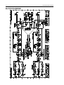
1
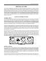
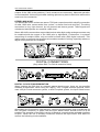
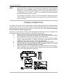
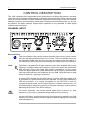
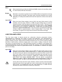
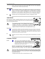
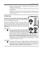
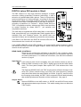
1962 DIGITAL VACUUM TUBE PRE-AMP OPERATORS MANUAL i TWELVE MONTHS LIMITED WARRANTY DRAWMER ELECTRONICS LTD., (HEREIN AFTER KNOWN AS THE MANUFACTURER) WARRANTS THIS AUDIO PRODUCT TO BE FREE FROM DEFECTS AND CONFORM SUBSTANTIALLY TO THE SPECIFICATIONS OF THIS MANUAL FOR A PERIOD OF TWELVE MONTHS FROM THE ORIGINAL DATE OF PURCHASE, WHEN USED IN ACCORDANCE WITH THE SPECIFICATIONS DETAILED IN THIS MANUAL. THIS WARRANTY IS NOT TRANSFERABLE. IT APPLIES ONLY TO THE ORIGINAL PURCHASER OF THE PRODUCT. THIS GUARANTEE DOES NOT COVER ANY PRODUCT, OR PARTS, OR FUSES THAT HAVE BEEN SUBJECTED TO MISUSE, NEGLECT, ACCIDENT OR ABNORMAL CONDITIONS OF OPERATION. ADDITIONALLY, THIS WARRANTY IS VOID IF THE PRODUCT HAS BEEN MODIFIED OR DAMAGED BY UNAUTHORISED REPAIR. IN NO EVENT WILL THE MANUFACTURER BE LIABLE FOR ANY DIRECT, INDIRECT, SPECIAL, INCIDENTAL OR CONSEQUENTIAL DAMAGES RESULTING FROM ANY DEFECT IN THE PRODUCT, INCLUDING LOST PROFITS, DAMAGE TO PROPERTY, AND, TO THE EXTENT PERMITTED BY LAW, DAMAGE FOR PERSONAL INJURY, EVEN IF THE MANUFACTURER HAS BEEN ADVISED OF THE POSSIBILITY OF SUCH DAMAGES. THE MANUFACTURER SHALL NOT BE RESPONSIBLE FOR ANY DAMAGE OR LOSS DURING SHIPMENT TO AND FROM THE FACTORY OR ITS DESIGNATED SERVICE FACILITY. THIS WARRANTY IS IN LIEU OF ALL OTHER WARRANTIES, WHETHER ORAL OR WRITTEN, EXPRESSED, OR IMPLIED. THE MANUFACTURER MAKES NO OTHER WARRANTY EITHER EXPRESS OR IMPLIED, INCLUDING, WITHOUT LIMITATION, ANY IMPLIED WARRANTIES OF MERCHANTABILITY, FITNESS FOR A PARTICULAR PURPOSE, OR NON-INFRINGEMENT. THE PURCHASER’S SOLE AND EXCLUSIVE REMEDY UNDER THIS WARRANTY SHALL BE REPAIR OR REPLACEMENT AS SPECIFIED HEREIN. THE MANUFACTURER RESERVES THE RIGHT TO MAKE CHANGES OR IMPROVEMENTS IN THE DESIGN AND CONSTRUCTION OF THIS UNIT WITHOUT OBLIGATION TO MAKE CHANGES OR IMPROVEMENTS IN THE PURCHASER’S UNIT. IN THE EVENT OF A FAILURE OF A PRODUCT COVERED BY THIS GUARANTEE, THE MANUFACTURER OR THEIR CERTIFIED REPRESENTATIVES WILL REPAIR AND CALIBRATE EQUIPMENT RETURNED, PRE-PAID, TO AN AUTHORISED SERVICE FACILITY WITHIN TWELVE MONTHS OF THE ORIGINAL PURCHASE FREE OF ANY CHARGE. ANY FAULT CAUSED BY MISUSE, NEGLECT, ACCIDENT, ACT OF GOD, WAR OR CIVIL INSURRECTION, ALTERATION OR REPAIR BY UNAUTHORISED PERSONAL, OPERATION FROM AN INCORRECT POWER SOURCE OR ABNORMAL CONDITIONS OF USE WILL NOT BE COVERED BY THIS WARRANTY. IN THE CASE OF A VALID WARRANTY CLAIM, YOUR SOLE AND EXCLUSIVE REMEDY AND DRAWMER’S ENTIRE LIABILITY UNDER ANY THEORY OF LIABILITY WILL BE TO, AT DRAWMER’S DISCRETION, REPAIR OR REPLACE THE PRODUCT WITHOUT CHARGE, OR, IF NOT POSSIBLE, TO REFUND THE PURCHASE PRICE TO YOU. ANY DISPUTE ARISING FROM THIS WARRANTY SHALL BE SUBJECT TO ENGLISH LAW. THIS DOES NOT AFFECT YOUR STATUTORY RIGHTS. ii CONTENTS SAFETY CONSIDERATIONS page 1 INTRODUCTION page 2 APPLICATIONS page 3 INSTALLATION " Audio connections " Digital connections " Power connections page page page page 4 4 5 7 CONTROL DESCRIPTIONS: " Channel Input " Limit " Microphone Pre-amplifier " Auxiliary Input " Line Input " High and Low Pass Filters " Fine Tune EQ " Enhance " Tube Drive " Stereo Mix " Digital Section D62-T/-A (where fitted) " Stereo Link operation page page page page page page page page page page page page page 8 8 8 9 9 10 11 11 12 13 14 15 19 CONFIGURATION: " Internal jumpers page 19 IF A FAULT DEVELOPS page 20 CONTACTING DRAWMER page 20 TECHNICAL SPECIFICATION page 21 BLOCK DIAGRAM page 22 iii For the USA FEDERAL COMMUNICATIONS COMMISSION RADIO FREQUENCY INTERFERENCE STATEMENT This equipment has been tested and found to comply with the limits for a Class B digital device, pursuant to Part 15 of the FCC Rules. These limits are designed to provide reasonable protection against harmful interference in a residential installation. This equipment generates, uses and can radiate radio frequency energy and, if not installed and used in accordance with the instructions, may cause harmful interference to radio communications. However, there is no guarantee that interference will not occur in a particular installation. If this equipment does cause interference to radio or television reception, which can be determined by turning the equipment off an on, then the user is encouraged to try to correct the interference by one or more of the following measures: < Reorient or relocate the receiving antenna. < Increase the separation between the equipment and the receiver. < Connect the equipment into an outlet on a circuit different from that to which the receiver is connected. < Consult the dealer or an experienced radio/TV technician for help. Unauthorised changes or modification to this system can void the users’ authority to operate this equipment. This equipment requires shielded interface cables in order to meet FCC class B limit. For Canada CLASS B NOTICE This digital apparatus does not exceed the Class B limits for radio noise emissions set out in the Radio Interference Regulations of the Canadian Department of Communications. CLASSE B AVIS Cet appareil numérique ne dépasse pas les limites de la classe B au niveau des émissions de bruits radioélectriques fixés dans le Règlement des signaux parasites par le ministère Canadien des Communications. COPYRIGHT This manual is copyrighted © 1997 by Drawmer Electronics, Ltd. With all rights reserved. Under copyright laws, no part of this publication may be reproduced, transmitted, stored in a retrieval system or translated into any language in any form by any means, mechanical, optical, electronic, recording, or otherwise, without the written permission of Drawmer. All brand or product names mentioned in this manual are trademarks or registered trademarks of their respective owners. iv 1 1962 OPERATORS’ MANUAL DRAWMER 1962 Digital Vacuum Tube Pre-Amp SAFETY CONSIDERATIONS CAUTION - MAINS FUSE TO REDUCE THE RISK OF FIRE REPLACE THE MAINS FUSE ONLY WITH A FUSE THAT CONFORMS TO IEC 127-2. 250 VOLT WORKING, TIME DELAY TYPE AND BODY SIZE OF 20mm x 5mm. THE MAINS INPUT FUSE MUST BE RATED AT 250mA WHERE THE MAINS INPUT VOLTAGE SWITCH IS SET TO 230 VOLTS AC. AND 500mA WHERE THE MAINS INPUT VOLTAGE IS 115 VOLTS AC. CAUTION - MAINS CABLE DO NOT ATTEMPT TO CHANGE OR TAMPER WITH THE SUPPLIED MAINS CABLE. CAUTION - SERVICING DO NOT PERFORM ANY SERVICING. REFER ALL SERVICING TO QUALIFIED SERVICE PERSONNEL. WARNING TO REDUCE THE RISK OF FIRE OR ELECTRIC SHOCK DO NOT EXPOSE THIS EQUIPMENT TO RAIN OR MOISTURE. 2 1962 OPERATORS’ MANUAL INTRODUCTION The 1962 is a hybrid vacuum tube/semi-conductor, dual-channel pre-amplifier which features extremely low noise operation and the option of a 24-bit digital output. Balanced microphone and line inputs are included making the 1962 a powerful and versatile tool in all areas of audio, including studio recording, live sound, location recording, postproduction, mastering and as part of a musician's rack system. In addition to providing 'clean gain', the 1962 includes variable high and low-pass shelving filters, a 3-band 'sweetening' EQ, high and low frequency enhancement plus a switchable peak limiter. A variable Tube Drive system enables the user to apply a precise amount of tube colouration while a simple mixing system provides level and pan control for each of the two channels. The optional D62-T or D62-A digital convertor module may be ordered with the 1962 or retrofitted when required and provides 16, 18, 20 or 24-bit wordlength outputs in both AES/EBU and S/PDIF formats with user selectable dither. The D62-T also includes a Tascam™ T-DIF interface while the D62-A has an integral ADAT™ optical interface. Word sync in and out is provided as standard and the user may select between 48kHz, 44.1kHz and externally clocked sample rates. This manual will refer to the digital module as the D62 wherever it is applicable to both T-DIF and ADAT. One major advantage of the hybrid approach is that it combines the dynamic range, reliability and stability of modern solid-state designs with the warm, detailed sound of vintage classic tube designs. The microphone input stages feature extremely low noise, balanced input circuitry followed by true, high voltage tube amplification, enabling modern microphones to take on the characteristics of older tube models. Phantom power is individually switchable on the two microphone inputs and each microphone input has a phase reverse switch. The line/instrument pre-amplifiers are compatible with a variety of signal sources, from electric guitars and basses to stereo electronic keyboards and synthesizer modules. By overdriving the tube stage, tonal colouration may be added to an instrument, and with the addition of an external speaker simulator, overdriven guitar, synth or organ sounds may be Direct Injected into the mixing console. There are two, dual-stage tubes in the audio signal path and, in order to maintain optimum signal purity, the EQ, enhancement and tube drive stages may be switched out of circuit to provide a minimum signal path between the input and output. To maintain the highest possible signal-to-noise performance, continuously variable input gain controls are used instead of rotary switches and high resolution, 24-element LED metering is provided along with peak overload LEDs. Output level metering and gain control is provided and each channel has a switchable limiter, which can be used to prevent unwanted overloading particularly important when driving digital equipment or when using the optional digital output stage. A Gain Reduction LED monitors the limiter action. Console-style insert points on the rear panel allow additional processing to be added to the signal path. Up to a maximum of three additional stereo analogue signals can be mixed together with the internally processed signal(s) by utilising the rear panel connector. Providing a facility to fit only one 1962 with the D62 analogue to digital convertor module. 3 1962 OPERATORS’ MANUAL APPLICATIONS Standalone microphone preamplifiers are generally associated with direct-to-stereo recording or with the purist recording approach by which the traditional console is bypassed wherever possible. Though ideally suited to these applications, and to applications where instrument level signals require to be DI'd, the 1962 is much more flexible than traditional preamplifiers, because of its variable Tube Drive control and its versatile equaliser/enhancer section. Because of its ability to modify and enhance the tonal quality of a signal, the 1962 is perfectly suited to stereo mix processing, subgroup processing, or to discerning mastering operations where the digital output may be used directly to feed a digital tape or disk-based editing machine. The subtle tube colourations add warmth, depth and transparency to a mix while emphasising mid-range and high-frequency detail. For high quality location recording, the 1962 makes the perfect partner for a DAT machine, combining the functions of stereo mic preamp with the capability to output high resolution digital data with up to 24-bit word length. The mic inputs provide up to +60dB of gain while closely approaching the theoretical minimum noise level; the performance of the 1962 is invariably determined by the quality of the microphones plugged into it rather than by any inherent limitations. As an instrument amplifier, the 1962 provides a warm-sounding tube input, making it ideal for DI'ing guitars, basses and even keyboards. The tube gain stages are versatile enough to provide a clean, punchy sound or the gain may be increased to provide the type of overdrive sound associated with tube guitar amplifiers. Although the EQ facilities offered on the 1962 are designed mainly for sweetening, they have sufficient range to be used in a creative context when creating instrument sounds. The limiter may be used to prevent the output level from clipping when the maximum level of the input signal cannot be established with certainty. 4 1962 OPERATORS’ MANUAL INSTALLATION The 1962 is designed for standard 19" rack mounting and occupies 2U (88mm) of rack space. Avoid mounting the unit directly above power amplifiers or power supplies that radiate significant amounts of heat, or in poorly ventilated or unusually warm environments. We advise that a blank space above the unit with a ventilated rack blanking panel is fitted. Fibre or plastic washers may be used to prevent the front panel becoming marked by the mounting bolts. In mobile systems, it is recommended that a shock resistant flight case is used. In severe conditions where there might be excessive vibration, additional rear support might be required. AUDIO CONNECTIONS CHANNEL IN/OUT The channel inputs and outputs are electronically balanced on conventionally wired XLRs (pin1 screen, pin 2 hot, pin 3 cold and XLR shell is connected to the chassis), with an operating level nominally of +4dBu. If the unit is to be used where it may be exposed to high levels of disturbance (such as found close to a TV or radio transmitter), we suggest that the screen of the signal cable be connected to the chassis connection on the XLR connector as opposed to connecting to pin1. The 1962 fully conforms to the EMC standards. If ground loop problems are encountered, never disconnect the power inlet earth, but instead, try disconnecting the signal screen on one end of each cable connecting the outputs of the 1962 to the patchbay. If such measures are necessary, balanced operation is recommended. Various signal cable earthing options may have to be tried to achieve the most hum-free connection. The intended use of the audio insert jacks would be to patch in an additional EQ (eg Drawmer 1961), reverb or similar processing to the signal path. Insert connection is via quarter-inch TRS jacks, the wiring convention being: ring - signal send, tip - signal return and sleeve - ground. The insert jack may be permanently wired to a normalised patch bay for easier connection. The signal path to and from this insert jack and enhance any external processing can be overridden by disabling the Fine EQ section. STEREO OUTPUTS The Stereo Mix Output XLRs are electronically balanced and follow the usual wiring convention of: pin 1 screen, pin 2 hot, pin 3 cold and XLR shell connected to the chassis. If the unit is to be used where it may be exposed to high levels of disturbance (such as close to a TV or radio transmitter), we suggest that the screen of the signal cable be connected to the chassis connection on the XLR connector as opposed to connecting to pin1. The 1962 fully conforms to the EMC standards. If ground loop problems are encountered, never disconnect the power inlet earth, but instead, try disconnecting the signal screen on one end of each cable connecting the 5 1962 OPERATORS’ MANUAL outputs of the 1962 to the patchbay. If such measures are necessary, balanced operation is recommended. Various signal cable earthing options may have to be tried to achieve the most hum-free connection. STEREO MIX IN/OUT The Stereo Mix In/Out sockets are stereo TSR jack connections which simplify connection of other 1962 units, stereo sends from a mixer, or similar line level device(s). The wiring convention is: ring, right channel, tip, left channel and sleeve ground. These signals are unbalanced and operate at a nominal +4dBu level. Stereo Mix In/Out connections are provided so that other high quality analogue sources may be combined with the output of the 1962 prior to digitisation. Furthermore, in systems comprising of multiple 1962s, only one need be fitted with a D62 digital converter. This option saves on cost and also provides a convenient method of mixing, especially where no digital mixing facilities are available. DIGITAL CONNECTIONS (Only where D62-T or D62-A module is fitted) DIGITAL CLOCK SYNCHRONISATION When clocking the D62 from an external, master clock source, there are two possible methods of termination. When using the TEAC® TDIF-1 Digital Interface protocol, which uses a 25 pin D-sub connector system, or ADAT® optical system, the Input Select button should be in the Out position. Alternatively, external synchronisation may be achieved via the 75Ω BNC connector, in which case the Input Select button should be set to its IN position. The operation of the D62-A version is identical, except that the multitrack interface is ADAT. When the unit is suitably connected, observe the Input Select LED status to confirm the following clock conditions: 6 1962 OPERATORS’ MANUAL z The LED will illuminate brightly and steadily if a reliable and compatible clock source is recognised. The LED will blink when External Clock is selected on the front panel, but no external clock is detected. ' The LED will flicker dimly if the clock signal is inadequate due to problems such as level matching or signal corruption. Typical causes of such problems are: the connected cable is too long or of an incorrect type; the external clock signal has deteriorated in quality to a point where it cannot be read reliably. When External Clock is selected on the front panel, a reconstituted version of the input word clock is available at the Word Sync Output BNC connector. DIGITAL DATA Three digital data output formats are supported by the D62 digital interface. AES/EBU: via an XLR connector designed to be used with standard balanced microphone cable (20 metres maximum), wired pin 1 screen, pin 2 and 3 balanced data, and the XLR shell connected to the chassis. Having many short cables joined together is not advisable as each connector can cause undesirable signal reflections. The AES/EBU output is enabled when the Output Select button is in its Out position. The status LED illuminates to confirm this mode has been selected. The output socket fully conforms to the EMC standards; if the unit is to be used where it may be exposed to high levels of disturbance, such as found close to a TV or radio transmitter, it is suggested that the screen of the data cable be connected to the chassis connection on the XLR type connector rather than to pin 1. If ground loop problems are encountered, never disconnect the mains ground, but instead, try disconnecting the signal screen on one end of each cable connecting the outputs S/PDIF: via a high quality RCA type phono jack where the data conforms to the Sony™ Phillips™ Digital InterFace format. Because this connector only provides an unbalanced termination, the recommended maximum length for this cable is 3 metres, even with very high quality cable. This socket is enabled when the Output Select button is set to its IN position; the status LED illuminates to confirm selection of this mode. TDIF: (Where the D62-T is fitted). This is permanently enabled and presents the digital data in the standard paired formats. If connection is to a Tascam™ DA88 or DA38, we strongly recommend using the Tascam accessory Dubbing cable PW-88D which is 1metre in length. We have also successfully used the 5 metres cable PW-88DL, but external interference might make digital data or timing signals unreliable. 7 1962 OPERATORS’ MANUAL ADAT: (Where the D62-A is fitted). This is permanently enabled and presents the digital data to the standard Alesis™ format, where the stereo signal is available on all eight tracks for the operator to choose which tracks to record. If connection is to a Alesis™ ADAT it is suggested that professionally terminated optical cables are used. For additional information, refer to the documentation accompanying the TDIF or ADAT compatible recording or storage device to which this socket is to be connected. POWER CONNECTION The 1962 unit will have been supplied with a power cable appropriate for domestic power outlets in your country. For your own safety it is important that this cable is used. The unit should always be connected to the power inlet earth using this cable. Never disconnect this unit from the mains supply earth. If the unit is to be used at a power input voltage which is different to that as supplied, the following procedure must be carried out. (See following diagram) 1: Disconnect the unit from the mains by removing the power cable. 2: Using a number 1 size pozidrive screwdriver, remove the two screws holding the voltage selection switch cover plate on the rear panel. 3: Remove the cover plate and slide the switch fully to its opposite position using a small screwdriver or similar instrument. Note that only nominal voltages of 230V and 115V (50 - 60Hz), are supported. 4: Rotate the cover plate one half turn, (180E) and refit the two screws. 5: Remove the fuse from the drawer beneath the power inlet. Fit a correctly rated fuse for the selected operation voltage. 6: Reconfirm that the correct voltage has been selected before reconnecting the mains. Operation at an incorrect mains voltage may cause serious damage to the unit, and invalidate the warranty. 8 1962 OPERATORS’ MANUAL CONTROL DESCRIPTION The 1962 comprises two independent audio channels plus a Stereo Mix section, and both channels may be operated independently or linked for stereo operation. When used in linked mode, the control-circuitry for both channels responds to the average of the two channel settings. It helps to avoid confusion if both sets of channel controls have similar, or, as near as possible, the same settings. Digital output capability is only available if a D62 digital interface has been fitted. CHANNEL INPUT Source Select: This four-position rotary switch selects the audio input source, which can be Mic, Mic with 48V phantom power, Line or Aux. The Line and Mic inputs are via rear-panel XLRs while the Aux input jack is located on the front panel. A red LED shows when the phantom powered mic option has been selected. Limit: The limiter is available for all input selections and, when enabled, will prevent clipping in situations where the maximum input level cannot be determined with accuracy. Use of the limiter also makes it possible to run the output closer the digital peak level (0dB) without the risk of clipping. Note that with Line input selected the Limit headroom is only 10dB. Large amounts of gain could exceed this, resulting in distortion. A status LED indicates that the limit function is active, and if the signal level is increased to a point where the limiter operates, the GR (Gain Reduction) LED will illuminate. It is usually acceptable for the GR LED to flash on occasional signal peaks, but if it lights regularly or almost continuously, it is invariably best to reduce the input level using the input gain control, and/or adjusting the EQ and Tube Drive settings. For stereo operation, the limiters should either both be active, or, both bypassed, to prevent an unwanted image shift(s) during limiting. As with all limiters, excessive amounts of limiting will be audible, but used carefully, the limiter offers protection against transient clipping while retaining tonal transparency. 1962 OPERATORS’ MANUAL 9 MICROPHONE PRE-AMPLIFIER The microphone input stage is based around an advanced, discrete component design, characterised by extremely low levels of noise and distortion. The audio performance is significantly better than what is normally achieved by the input stage of a typical, high quality recording console. When the tube and EQ sections are out of circuit, the mic preamp provides a high quality, minimum signal path to the output, making it ideal for direct connection to a tape machine or, if the D62 digital interface is installed, to the digital input of a digital multitrack recorder, DAT machine or hard disk recorder. The tube and EQ stages may be switched into circuit for applications where it is desirable to 'enhance' the signal prior to recording. Input Gain: When the Input Select switch is set to either MIC or 48V(MIC), the Input Gain control is fully variable over the range -25dB (attenuation or ‘pad’ for powered microphone systems) through to +60dB; the gain setting may be read off using the white coloured graticule around the Gain control. The input level meter must be monitored while adjusting the input gain so that average programme level is between -18dBfs and -12dBfs while the highest peak signal level never exceeds 0dBfs. This will permit a programme headroom of about 18dB (or approximately 3 bits of digital data). If the Peak LED illuminates, the gain is too high and should be reduced accordingly. Phase Rev: Depressing this button inverts the phase of the microphone input signal (only). Normally, a positive pressure at the microphone diaphragm produces a positive voltage at pin2 of the XLR output socket, but when Phase Rev is active, the inverse is true. Use of the Phase Rev feature is usually required only in multi-mic situations where phase anomalies or arrival time discrepancies need to be compensated for. It is advisable to check for mono compatibility when using phase reversal within a multi-mic arrangement. AUXILIARY INPUT To facilitate the connection of instrument sources, an unbalanced Auxiliary input jack is provided. This drives a sophisticated instrument input stage which offers control over both gain and brightness. The Aux input has a 470KΩ impedance and is suitable for use with both active and passive guitar pickup systems, electronic keyboards and similar sources. Though the 1962 is not designed to replace a dedicated guitar preamplifier, the Gain controls may be used to deliberately overdrive the input stage, which respond in a similar way to a tube instrument amplifier. For direct recording using significant amounts of overdrive, it is recommended that a speaker simulator be connected between the 1962 and the recorder, and that the sound be monitored post speaker simulator. A conventional EQ is not suitable for emulating the transfer characteristics of a guitar stack or combo system. 10 1962 OPERATORS’ MANUAL Gain: When depressed, provides an additional 20dB of gain to the auxiliary input. A Yellow status LED will illuminate. Bright: Switches in a 'presence' peak of around 10dB at 2KHz to simulate the voicing of a typical guitar amplifier. Because nearly all guitar amplifiers are voiced differently, it is likely that additional EQ will be required to achieve the desired sound. Input Gain: When the Input Select switch is set to AUX, the Input Gain control is fully variable over the range -25dB to +15dB; the gain setting may be read off using the yellow coloured graticule around the Gain control. The input level meter must be monitored while adjusting the input gain so that average programme level is between -18dBfs and -12dBfs while the highest peak signal level never exceeds 0dBfs. This will permit a programme headroom of about 18dB (or approximately 3 bits of digital data). If the Peak LED illuminates, the gain is too high and should be reduced accordingly. LINE PRE-AMPLIFIER The line input stage is based around an advanced, discrete component design, characterised by extremely low levels of noise and distortion. The performance is significantly better than what is normally achieved by the input stage of a typical, high quality recording console. When the tube and EQ sections are out of circuit, the line preamp provides a high quality, minimum signal path to the output, making it ideal for direct connection to a tape machine or, if the D62 digital interface is installed, to the digital input of a digital multitrack recorder, DAT machine or hard disk recorder. The tube and EQ stages may be switched into circuit for applications where it is desirable to 'enhance' the signal prior to recording. Input Gain: When the Input Select switch is set to LINE, the Input Gain control is fully variable over the range -25dB (attenuation) to +15dB; the gain setting may be read off using the yellow coloured graticule around the Gain control. The input level meter must be monitored while adjusting the input gain so that average programme level is between -18dBfs and -12dBfs while the highest peak signal level never exceeds 0dBfs. This will permit a programme headroom of about 18dB (or approximately 3 bits of digital data). If the Peak LED illuminates, the gain is too high and should be reduced accordingly. If using the Limiter with Line input selected, caution must be observed when large amounts of line input gain are used in conjunction with very high line input levels. It is feasible that the Line Limit headroom of 10dB could be exceeded in these conditions resulting in distortion. 1962 OPERATORS’ MANUAL 11 HIGH & LOW PASS The high and low pass filters are included to allow the user to attenuate undesirable sounds at the extremes of the audio spectrum, such as rumble, hum or hiss. They may also be used for creative applications, either on their own or in combination with conventional EQ. In order to make these filters effective in a variety of situations, they have been designed with fixed slopes and variable frequencies. Closing the two filters down so that any audio being converted to digital passes through unaffected can improve the signal-to-noise ratio of the digital data. High-Pass: A continually variable, 12dB per octave shelving, high-pass filter which may be adjusted over the range 15Hz to 400Hz. It may be used, for example, to attenuate microphone stand noise, traffic rumble or excessive low frequencies caused by a less than ideal choice of mic position. It may also be used to reduce the amount of low frequency spill from an adjacent instrument when the source being recorded is in a higher register than the source of interference. The High-Pass filter is also helpful in reducing the level of the fundamental frequency in mains hum, though it will not remove the harmonics that cause mains buzz . Low-Pass: A continually variable 12dB per octave shelving, low - pass filter which may be adjusted over the range 2kHz to 42kHz. It is useful in attenuating high frequency hiss or noise, especially where the programme material only contains low to medium harmonic frequencies - for example, electric guitar or bass tracks. In: Switches both the Low- and High-Pass filters into, or out of, circuit. A red LED indicates that the filters are in circuit. If only one filter is required, the other should be set to the extreme of its frequency range so as not to affect the signal being processed. FINE TUNE EQ The three controls in this section provide a subtle degree of control over the audio and are designed for audio sweetening rather than for radical signal reshaping. This section should not be confused with the type of equalisation that might be offered on a mixing desk or parametric type unit. A rear panel insert jack is connected in series with the Fine EQ section, so the In/Out button simultaneously bypasses any external processor connected via the channel insert point. 12 1962 OPERATORS’ MANUAL Low Fine Tune: Continually variable 6dB per octave shelving filter, providing up to 12dB of cut or boost. This control may be used to add 'warmth' to the signal being processed or to moderate excessive low frequency content. Mid Fine Tune: Continually variable 6dB per octave bandpass control providing up to 12dB of cut or boost. The centre frequency of 1KHz has been chosen to emphasise 'bite' or presence. High Fine Tune: Continually variable 6dB per octave shelving filter providing up to 12dB of cut or boost. This control may be used to moderate excessive brightness or to add a high frequency 'gloss'. In: When depressed, the push button will place the Fine Tune EQ and the Channel Insert rear panel Jack in circuit. A red status LED indicates such a situation. When this section is bypassed, any processor connected via the insert point will also be bypassed. The Fine Tune EQ controls (and any external inserted process(es)) come before the Peak Limiter in the signal side chain. Adding gain either via EQ boost or by external processing will result in a greater degree of limiting unless the input gain is reduced. ENHANCE The 1962 includes advanced circuitry designed to enhance transient detail by dynamically controlling the phase and spectral content of the programme material. The LEDs above the Enhance controls show the degree of enhancement taking place, and turning the Enhance control clockwise increases the amount of processed signal added back into to the programme material. If the Enhance controls are rotated fully clockwise and dynamic material is processed, the yellow LEDs will seem to be illuminated constantly. In reality, dynamic enhancement will still be occurring, but the peaks may be so close together that the LED will appear to be lit continuously. The Enhance circuitry comes before the Peak Limiter in the signal side chain. Although only small amounts of additional level will be generated in normal use, high settings of the Enhance controls may result in more frequent Limiting unless the input gain is reduced. Low Enhance: The low frequency enhance circuit is a level dependant filter designed to emphasise low frequency harmonics according to the dynamic nature of the programme material. At low signal levels, the degree of enhancement is greater than at higher signal levels, which has the result of increasing the subjective loudness of the material. The control is continually variable and is designed to be adjusted so that the LED above illuminates periodically. If the input signal is near the maximum operating level (0dB on the input meter) then no low frequency enhance will 13 1962 OPERATORS’ MANUAL occur, but as the signal level falls below 0dB, low level, low frequency transients will be enhanced proportionally. High Enhance: This continually variable control applies enhancement by increasing the amount of harmonic energy already present in high-frequency, transient signals. The control should be adjusted until the LED above illuminates periodically. Used carefully, High Enhance will increase the subjective definition of a sound without increasing its level by any significant degree. In: Activates the Low and High Enhance circuitry and lights the LED. TUBE DRIVE Each channel contains a specially designed tube circuit with variable drive, designed to emulate the classic tube sound of vintage equipment in a fully controllable manner. The tube drive control comes before the Peak Limiter in the signal side chain, so it is feasible that using high settings of tube drive on certain types of programme material may cause the signal level fed into the Limiter stage to increase. This will result in increased limiter activity. Tube Drive: A continually variable control that regulates the amount of tube colouration. Note that even at the control’s most counter-clockwise position some tube warmth will be added. To disable any tube effect fully, the section must be disabled using the push button switch. In: Switches the tube circuitry into the signal path and illuminates the status LED. CHANNEL OUTPUT Level: The Level control regulates the signal level available at the rear panel Channel Output XLR. The gain range is from -15dB to +20dB, and the output level is shown on the 8-segment meter placed directly above the Level control. Normally, the signals fed to the Mix output stage (and hence to the digital output), are independent of the channel level control settings. This is the optimal and factory configuration. There is an option (although less desirable) for the Mix section and the Digital Source Chs (channels) feed to be made post-level control by changing two PCB jumpers inside the unit (one per channel). This is not the best option for several reasons: 1) Digital output noise will be increased by up to 4dB. 14 1962 OPERATORS’ MANUAL 2) There is a greater chance of a digital overload, undoing the control and safety feature of the limiter. 3) Any digital output level will be un-calibrated, unless the control is set to the +20dB position. Clarification of this routing can be made using the block diagram at the rear of this manual. For details of how to modify these jumpers, see Configuration Jumpers on page 19. STEREO MIX The stereo mix section provides overall level and independent pan control over the two channel signals, which are available at the stereo mix section of the rear panel via two balanced XLRs, and on one unbalanced stereo jack. To expand the flexibility of the 1962 further, up to three mix signals from other Drawmer 1962s or comparable line level stereo sources may be mixed in with the channel signals via the rear panel Stereo Mix jack inputs. This allows other analogue equipment to use the high quality digital output stage of the 1962 (if fitted). Channel Pan: This control pans (‘positions’) the channel signal between the left and right stereo outputs. When a conventional stereo mix is required, or when a stereo mic array is being used, then the channel pan controls will normally be panned hard left and right. Stereo meters are provided within the Stereo Mix section. For optimum use, ensure that both Stereo Mix output meters track evenly. Note for maximum analogue signal headroom the 1962 does not suffer any signal level loss when panned centrally between the channels, This is unlike the traditional operation of a pan control on a mixing console. See also Configuration Jumpers on page 19 Output Level: A continually variable stereo control that sets the level of the Mix outputs. The gain range is from -15dB up to +20dB. Adjustment of this control does not affect the level seen by the digital section, whatever the position of the configuration jumpers. The signal levels of the two channels are visible on the two vertical 8 segment meters in the Stereo Mix section. 1962 OPERATORS’ MANUAL 15 DIGITAL (when D62 module is fitted) The D62 module is a very high resolution analogue to digital converter utilising proprietary Drawmer technology. It has a selection of sophisticated dither options. There is a proprietary system enabling up to 23-bit wordlength recordings to be made across three tracks of a digital multitrack where the multitrack machine is less than 24-bit resolution. In the case of the D62-T, recording is possible on a Tascam™ DA88, DA98, DA38 or TDIF-1 compatible machine, whereas the D62-A card provides an optical interface for Alesis ADAT™ (all variants) and compatible machines. The 1962 may be supplied with a D62 ready fitted, or one may be fitted retrospectively as a straightforward field upgrade that is available from your Drawmer dealer. No special tools are required for fitting, and no calibration procedures are necessary. If the D62 is not fitted then the DIGITAL section LEDs will not illuminate and the controls will not operate. If any WORD LENGTH yellow LED is flashing, an unrecoverable power ‘brownout’ (glitch) has caused the DSP to mute its digital outputs. Switch the power Off and On again to restore normal operation. REAR PANEL CONTROLS: There are two push-button switches on the D62-T rear connector panel. These should only need setting during installation as they define input and out cable preferences. For additional information, see the D62 Installation section on page 5. Input Select: If an external word clock is available, this push button selects its source. Either the BNC connector or the TDIF-1 digital input can be the 1962 master clock. The front panel Sample Rate option EXT CLK activates this clock source. The External WORD SYNC and TDIF clock inputs are filtered through a lownoise PLL (Phase Locked Loop) in the D62, the clock frequency (sample rate) should be within the range 29KHz to 51KHz. If the PLL cannot lock to the incoming clock reliably, the EXT CLK front panel LED will flash indicating that audible glitches and distortion will be introduced. See page 5. Output Select: Selects AES/EBU via the XLR socket, or, S/PDIF via the RCA Phono socket with appropriate data output formats. This switch setting does not affect the T-DIF output. 16 1962 OPERATORS’ MANUAL 1962 FRONT PANEL DIGITAL CONTROLS: Sample Rate: This switch selects 48.0KHz, 44.1KHz and EXTernal clock for synchronising to other digital devices. Any external clock input is ‘cleaned’ by the D62 PLL and output at the rear panel BNC connector marked WORD SYNC Out. Reduce monitor volume levels before casually selecting ‘EXT CLK’, selecting it without any external clock connected results in a nasty 0dBfs digital noise being output! Word Length: Selects the word length (bit resolution) of the audio samples to be 24, 20, 18 or 16 bits. Match this to your digital recording, storage or processing device. Selecting ‘16’ sends 4 x stereo pairs of tracks to the TDIF output, while 24,20 and 18 sends high resolution tracks to the TDIF for recording on tracks 1,2,3 or 5,6,7. Source: Select ‘Chs’ for the most direct audio path (thus: highest performance) to the D62 analogue-to-digital convertor, or ‘MIX’ which inserts the CHAN PAN controls to the path. MIX also enables up to 3 additional analogue inputs (eg. stereo outputs from other 1962 units) to be mixed via the rear panel Stereo Mix inputs to the master D62 digital output. Pre- or post- output level control is selectable on two internal jumper links. See configuration jumpers section on page 19. In all configurations the audio signal to the D62 passes through a ‘Soft clip’ circuit, therefore short transient audio peaks will not cause noticeable distortion on the digital outputs. See the Block Diagram Dither: 1 - 12: This affects the type of dither added to the audio signal when recording with WORD LENGTH less than 24 bits. Position 1 is generally the best compromise and places all of the dither noise at the high end of the audio spectrum, where the ear is least sensitive. In the majority of situations, this will produce excellent results. The other 10 positions progressively reduce the level of the dither, spreading it further down the audio spectrum. Position 11 is standard ‘White noise’ dither and position 12 is dither OFF. See DITHER SELECTOR OPTIONS table, on the following pages for more details. Care must be taken when applying heavy (more than +30dB) post EQ HF boost to noise shaped dithered recordings as excessive HF levels can be generated, possibly causing damage to speaker tweeters. Noise shaped dither is effective when a WORD LENGTH is selected of less than 24 bits. It effectively decreases distortion and noise on low level signals when compared with unshaped dithering; an apparent digital noise floor reduction of 12 to 18dB should be perceived. 1962 OPERATORS’ MANUAL 17 Dither (cont.): REPLAY A, B, C, D: The four positions A, B, C and D (in yellow) are used for playback from a digital multitrack recorder to the AES/EBU and SPDIF outputs, 16bit or High resolution mode will be automatically selected. Which specific tracks are replayed are detailed at the bottom of the table on the following page. If high resolution tracks are replayed with any of the tracks missing audible distortion will be heard. RECORDING: The multitrack tape must be pre-formatted at the required sample rate with Emphasis Off before recording from the D62. When recording to a multitrack machine, the SAMPLE RATE should be set to EXT CLK and the rear panel INPUT SELECT set to TDIF/ADAT as the multitrack tape machine must supply the master clock. Note: On the DA88/DA38 the ‘Fs’ LED will flash, it does not affect the recording. High resolution recording: When the required resolution is greater than that of the multitrack machine, the 1962 splits the 2 digital signals into 3 channels, where the 3rd channel is used to store the remainder bits. For example, when using a 16bit multitrack machine to record a stereo 24bit signal, tracks 1,2, and 3 (or 5,6 and 7) must be selected. The third channel sounds like white noise and is used to reconstruct the 24bit signal on playback. With the availability of 20bit and 24bit machines, there is no need to split signals below the word length of the machine, so 3 software versions are available to ensure full compatibility. 16bit version. When 'WORD LENGTH' is set to 16 bit, signals are recorded to multitrack without splitting, so all 8 tracks are available. If 'WORD LENGTH' is set to 18, 20 or 24bit signals are split into 3 tracks (1+2+3 or 5+6+7). 20bit version. When 'WORD LENGTH' is set to 16, 18 or 20 bit, signals are recorded to multitrack without splitting, so all 8 tracks are available. If 'WORD LENGTH' is set to 24bit, signals are split into 3 tracks (1+2+3 or 5+6+7). 24bit version. With this version, there is no need to split the signals, so whichever resolution is selected, signals are recorded directly, leaving all 8 tracks available for use. It is important to remember that for any high resolution recording to be successful, the (tape) operator must enable recording on ALL of the tracks of the chosen output group (1+2+3 or 5+6+7). 18 1962 OPERATORS’ MANUAL DITHER SELECTOR OPTIONS Position Dither and Noise Shaping 1 Positions the noise shaped dither to the very top of the audio spectrum at a level of +30dB above the quantise noise floor. Because the ears are very insensitive at this frequency, the noise is inaudible, resulting in a subjectively clean signal with a wide dynamic range. Adding extreme HF EQ boost at a later stage is not recommended. 2 The same frequency as 1 (above) with only +20dB of boost. The reduction in level slightly increases distortion, but the tolerance to HF EQ on replay is increased. 3 Shaped dither above 17KHz @ +30dB. 4 Shaped dither above 17KHz @ +20dB. 5 Dual slope filtered dither above 16KHz @ +10dB. A particularly effective setting combining subjective neutrality with a worthwhile increase in dynamic range and high tolerance to post HF EQ. 6 Shaped dither above 14KHz @ +20dB. 7 Shaped dither above 14KHz @ +15dB. 8 Shaped dither above 12KHz @ +15dB. 9 Smooth, dual-slope filtered dither above 10KHz @ +10dB. A relatively gentle noise shaping with a worthwhile increase in dynamic range and a neutral sound. 10 Shaped dither above 10KHz @ +10dB. 11 White noise dither. No noise shaping. 12 Dither / Noise shaping OFF. Caution as a truncated word length will give distortion. A Tape Playback Tracks 1,2 & 3 in high resolution modes; tracks 1,2 in 16-bit mode. B Tape Playback Tracks 1,2 & 3 in high resolution modes; tracks 3,4 in 16-bit mode. C Tape Playback Tracks 5,6 & 7 in high resolution modes; tracks 5,6 in 16-bit mode. D Tape Playback Tracks 5,6 & 7 in high resolution modes; tracks 7,8 in 16-bit mode. 19 1962 OPERATORS’ MANUAL STEREO LINK Stereo Link: Averages the left and right channel signals to provide the same degree of gain reduction to both limiters and balance any low / high dynamic enhance. This prevents any image shifting which could occur whenever the left and right signal dynamics varied from each other by any significant degree. Stereo link is enabled when the LED is lit. If in stereo linked mode, then each processing module such as EQ, Tube Drive, etc. should ideally be set to the same settings, and simultaneously enabled, as the control-circuitry for both channels responds to the higher of the two channel settings, which could cause an image shift. CONFIGURATION Configuration Jumpers: A simple adjustment of two internal PCB jumpers (one for each channel) enables the front panel Channel Output Level setting to be passed onto the Channel Pan control in the Stereo Mix section and therefore onwards to the Digital Section. The normal and recommended factory setting for both jumpers is for Stereo Mix Channel Pan to be pre Channel Output Level control. It is less desirable option for the Mix section and the Digital Source Chs (channels) feed to be made post-level control for several reasons: 1) Digital output noise will be increased by 4dB. 2) There is a greater chance of a digital overload, undoing the control and safety feature of the limiter. 3) Any digital output level will be un-calibrated, unless the channel output level control is set to the +20dB position. To perform this change: 1: Disconnect the mains power cable from the unit. 2: With a number 1 pozidrive screwdriver, remove the 8 screws that retain the top cover. (ie: two on each side; two at the rear and two counter-sunk screws along the top at the front edge). 3: Locate the jumper blocks referenced as J12. < For channel 1 (or left) this is the upper PCB. The jumper is centrally positioned along the rear edge of the PCB. < For channel 2 (or right) this is the lower PCB. Its jumper is central to the unit, near the small IDC connector for the digital unit. 4: Lift off the shorting jumper block and replace on the centre pin and previously free pin. In most cases, the jumper has been replaced by soldering the pins together. 5: Replace the top cover ensuring the correct screws are used for their intended positions. 20 1962 OPERATORS’ MANUAL IF A FAULT DEVELOPS For warranty service please call Drawmer Electronics Ltd. Or their nearest authorised service facility, giving full details of the difficulty. On receipt of this information, service or shipping instructions will be forwarded to you. No equipment should be returned under the warranty without prior consent from Drawmer or their authorised representative. For service claims under the warranty agreement a service Returns Authorisation (RA) number will be given. Write this RA number in large letters in a prominent position on the shipping box. Enclose your name, address, telephone number, copy of the original sales invoice and a detailed description of the problem. Authorised returns should be prepaid and must be insured. All Drawmer products are packaged in specially designed containers for the best adequate protection. If the unit has to be returned the original container must be used. If this container is not available, then the equipment must be packaged in substantial shock-proof material, capable of withstanding the handling for the transit. CONTACTING DRAWMER Drawmer Electronics Ltd., will be pleased to answer all application questions to enhance your usage of this equipment. Please address all correspondence to: Drawmer (Technical Helpline) : Coleman St.: Parkgate : Rotherham : S62 6EL : UK or, Email us on : [email protected] Drawmer dealers, Authorised service departments and other contact information can be obtained from our web pages on http://www.drawmer.com 21 1962 OPERATORS’ MANUAL TECHNICAL SPECIFICATIONS (All measurements taken at 0dBu operating level) MIC INPUT NOISE 20KΩ 150Ω to 600Ω 470KΩ -128.5dB (@ +60dB gain) MAXIMUM INPUT LEVEL OUTPUT IMPEDANCE MAXIMUM OUTPUT LEVEL ANALOG BANDWIDTH +28dBu 50Ω +22dBu (balanced) 15Hz to 22KHz -1dB INPUT IMPEDANCES LINE MIC AUX ANALOGUE DISTORTION (THD +n) ref. 1KHz Percentage Mic and Line input at unity gain 0.01% Line Input at 0dBu 0.025% Mic Input at 0dBu < 0.01% D62 specification with LINE input @ 0dBu, (all effects disabled): - 105dB (@ +0dB gain) CROSSTALK - 70dB (@ +0dB gain) THD+n @ 1Khz -2dB (soft clip) - 93dB (@ +0dB gain) THD+n @ 1Khz -20dB -120dB (@ +0dB gain) THD+n @ 1Khz -60dB -123dB (@ +0dB gain) NOISE FLOOR POWER REQUIREMENTS 100-120Volt or 195-250Volt at 50-60Hz, 38 Watts FUSE RATING 250mA for 230Volt, 500mA for 115Volt CONFORMING TO IEC 127-2 FUSE TYPE 20mm x 5mm, Class 3 Slo-Blo, 250Volt working CASE SIZE 482mm (w) x 88mm (h) x 250mm (d) WEIGHT (incl packaging) 6.5 Kgs (excluding D62-T/-A) 8 Kgs (including D62-T/-A) 22 BLOCK DIAGRAM 1962 OPERATORS’ MANUAL