Download Cables to Go 29350 Specifications

Transcript
Electric Chain
83874
Operating, Maintenance
& Parts Manual
®
Rated Loads
1/8 through 3-Tons
125 kg through 3000 kg.
Follow all instructions and warnings for
inspecting, maintaining and operating
this hoist.
The use of any hoist presents some risk of personal
injury or property damage. That risk is greatly
increased if proper instructions and warnings are
not followed. Before using this hoist, each operator
should become thoroughly familiar with all warnings,
instructions, and recommendations in this manual.
Retain this manual for future reference and use.
Forward this manual to the hoist operator.
Failure to operate the equipment as directed in the
manual may cause injury.
Before using the hoist, fill in the information below.
Refer to the hoist identification plate.
Model Number ____________________________
Serial Number ____________________________
Purchase Date ____________________________
Voltage __________________________________
Rated Load ______________________________
627-T
i
CM HOIST PARTS AND SERVICES ARE AVAILABLE IN THE UNITED STATES AND IN CANADA
As a CM Hoist user, you are assured of reliable repair and parts services through a network of Master Parts Depots and
Service Centers that are strategically located in the United States and Canada. These facilities have been selected on the
basis of their demonstrated ability to handle all parts and repair requirements promptly and efficiently.
Below is a list of the Master Parts Depots in the United States and Canada. To quickly obtain the name of the U.S. Service
Center located nearest you, call (800) 888-0985. Fax: (716) 689-5644. In the following list, the Canadian Service Centers are
indicated.
UNITED STATES MASTER PARTS DEPOT
CALIFORNIA
OTTO SYSTEMS, INC.
12010 Bloomfield Ave.
Sante Fe Springs, CA 90670
562/462-1612 or 800/596-7392
Fax 562/462-1617
or
7656 Las Positas Road
Livemore, CA 94551
925/245-8800 or 800/508-6886
Fax 925/245-8804
GEORGIA
ACE INDUSTRIES, INC.
6295 McDonough Drive
Norcross, GA 30093
770/441-0898 or 800/733-2231
Fax 800/628-3648
ILLINOIS
JOHN SAKASH COMPANY, INC.
700 Walnut Street
Elmhurst, IL 60126
630/833-3940
Fax 630/833-9830
INDIANA
HORNER ELECTRIC COMPANY, INC.
1521 East Washington Street
Indianapolis, IN 46201
317/639-4261
Fax 317/639-4342
IOWA
VM HOIST & CRANE SERVICES
PO Box 440
450 Highway 151
Walford, IA 52351
319/846-6040
Fax 319/846-6045
KANSAS
INDEPENDENT ELECTRIC MACHINERY
4425 Oliver Street
Kansas City, KS 66106
913/362-1155 or 800/833-2610
Fax 913/904-3330
LOUISIANA
BEERMAN PRECISION, INC.
PO Box 6018
Metairie, LA 70009
504/207-6000
Fax 504/207-6044
MASSACHUSETTS
ABEL DISTRIBUTORS, INC.
50 Parker Street, Unit 2
Newburyport, MA 01950
978/463-0700
Fax 978/463-5200
NEW JERSEY
SHUPPER-BRICKLE EQUIPMENT CO.
PO Box 803
2394 Route 130, Suite C
Dayton, NJ 08810
732/438-3888
Fax 732/438-3889
CANADIAN SERVICE CENTERS
NEW YORK
VOLLAND ELECTRIC EQUIPMENT CO.
75 Innsbruck Drive
Buffalo, NY 14227
716/656-9900
Fax 716/656-8898/8899
ALBERTA
BENNETT & EMMOTT, LTD.
18131 118th Avenue
Edmonton, Alberta T5S 1M8
403/454-9000
Fax 403/454-8990
NORTH CAROLINA
TEAM SESCO
PO Box 667489
2225 Freedom Drive
Charlotte, NC 28208
704/372-4832 or 800/487-3726
Fax 704/358-1098
**COLUMBUS McKINNON, LTD.
10311-174th Street
Edmonton, Alberta T5S 1H1
800/263-1997
Fax 403/486-6160
OHIO
MAZZELLA LIFTING TECHNOLOGIES
21000 Aerospace Parkway
Cleveland, OH 44142
440/239-5700 or 800/362-4601
Fax 440/239-7010
PENNSYLVANIA
AMICK ASSOCIATES, INC.
11 Sycamore Street
Carnegie, PA 15106-0529
412/429-1212 or 800/445-9456
Fax 412/429-0191
RAM MOTORS & CONTROLS, INC.
5460-B Pottsville Pike, Docks 8-11
PO Box 748
Leesport, PA 19533
610/916-8000
Fax 610/916-7957
SOUTH CAROLINA
ENGINEERED SYSTEMS INC.
1121 Duncan-Reidville Road
Duncan, SC 29334
864/879-7438 or 800/879-7438
Fax 864/879-6428
TEXAS
ABEL EQUIPMENT CO., INC.
3710 Cavalier Drive
Garland, TX 75042
972/272-7706
Fax 972/272-6955
HYDRAULIC EQUIPMENT SERVICES, INC.
1021 North San Jacinto Street
Houston, TX 77002
713/228-9601
Fax 713/228-0931
WISCONSIN
TRESTER HOIST & EQUIPMENT, INC.
W136 N4863 Campbell Drive
Suite #4
Menomonee Falls, WI 53051
262/790-0700 or 800/234-6098
Fax 262/790-1009
BRITISH COLUMBIA
FLECK BROTHERS, LTD.
4084 McConnel Court
Burnaby, British Columbia V5A 3N7
MANITOBA
KING’S ELECTRIC MOTORS, INC.
633 Tyne Avenue
Winnipeg, Manitoba R2L 1J5
204/663-5332
Fax 204/663-4059
NOVA SCOTIA
*W & A MOIR
95 Ilsley Ave.
Burnside Park, Nova Scotia B3B 1L5
902/468-7720
Fax 902/468-3777
ONTARIO
*R & W HOIST REPAIR, LTD.
790 Redwood Square
Units 5, 6, & 7
Oakville, Ontario L6L 6N3
905/825-5500
Fax 905/825-5315
*TORONTO ELECTRIC HOIST
SALES & SERVICE
9 CoDeco Court
North York, Ontario M3A 1A1
416/386-0820
Fax 416/386-0821
*MASLACK SUPPLY, LTD.
488 Falconbridge Road
Sudbury, Ontario P3A 4S4
705/566-1270
Fax 705/566-4208
*COLUMBUS McKINNON, LTD.
P.O. Box 1106
10 Brook Road, North
Cobourg, Ontario K9A 4W5
905/372-0153
Fax 905/372-3078
QUEBEC
*HERCULES SLING & CABLE
3800 TransCanada Highway
Pointe-Claire, Quebec H9R 1B1
514/428-5511514/48631-5511
Fax 514/428-5555
*LEGER PALANS ET OUTILLAGES, INC.
7995-17th Ave.
Montreal, Quebec H1Z 3R2
514/376-3050
Fax 514/376-0657
**ARE ALSO MASTER PARTS DEPOTS
**MASTER PARTS DEPOT ONLY
ii
SAFETY PRECAUTIONS
Each Lodestar Electric Hoist is built in accordance with the specifications contained herein and at the time of manufacture complied with our interpretation of applicable sections of the *American Society of Mechanical Engineers Code B30.16 “Overhead
Hoists,” the National Electrical Code (ANSI/NFPA 70) and the Occupational Safety and Health Act. Since OSHA states the
National Electrical Code applies to all electric hoists, installers are required to provide current overload protection and grounding
[on the branch circuit section] in keeping with the code. Check each installation for compliance with the application, operation
and maintenance sections of these articles.
The safety laws for elevators, lifting of people and for dumbwaiters specify construction details that are not incorporated into the
hoists. For such applications, refer to the requirements of applicable state and local codes, and the American National Safety
Code for elevators, dumbwaiters, escalators and moving walks (ASME A17.1). Columbus McKinnon Corporation cannot be
responsible for applications other than those for which CM equipment is intended.
L
!
*Copies of this standard can be obtained from ASME Order Department, 22 Law Drive, Box 2300, Fairfield, NJ 07007-2300, U.S.A.
THIS SYMBOL POINTS OUT IMPORTANT SAFETY INSTRUCTIONS WHICH IF NOT FOLLOWED
COULD ENDANGER THE PERSONAL SAFETY AND/OR PROPERTY OF YOURSELF AND
OTHERS. READ AND FOLLOW ALL INSTRUCTIONS IN THIS MANUAL AND ANY PROVIDED
WITH THE EQUIPMENT BEFORE ATTEMPTING TO OPERATE YOUR LODESTAR HOIST.
L
!
WARNING
Usage of hoists that do not involve lifting of the load on the
lower hook or using hoists in the inverted position without
special precaution may cause an accident resulting in injury
and/or property damage.
TO AVOID INJURY:
Consult Columbus McKinnon for information concerning
using hoists in these applications.
L
! WARNING
Improper operation of a hoist can create a potentially hazardous situation which, if not avoided, could result in death or
serious injury. To avoid such a potentially hazardous situation,
the operator shall:
1. NOT operate a damaged, malfunctioning or unusually
performing hoist.
2. NOT operate the hoist until you have thoroughly read
and understood this Operating, Maintenance and Parts
Manual.
3. NOT operate a hoist which has been modified.
4. NOT lift more than rated load for the hoist.
5. NOT use hoist with twisted, kinked, damaged, or worn
load chain.
6. NOT use the hoist to lift, support, or transport people.
7. NOT lift loads over people.
8. NOT operate a hoist unless all persons are and remain
clear of the supported load.
9. NOT operate unless load is centered under hoist.
10. NOT attempt to lengthen the load chain or repair damaged load chain.
11. Protect the hoist’s load chain from weld splatter or other
damaging contaminants.
12. NOT operate hoist when it is restricted from forming a
straight line from hook to hook in the direction of loading.
13. NOT use load chain as a sling, or wrap load chain
around load.
14. NOT apply the load to the tip of the hook or to the hook
latch.
15. NOT apply the load unless load chain is properly seated
in the chain wheel(s) or sprocket(s).
16. NOT apply load if bearing prevents equal loading on all
load supporting chains.
17. NOT operate beyond the limits of the load chain travel.
18. NOT leave load supported by the hoist unattended
unless specific precautions have been taken.
19. NOT allow the load chain or hook to be used as an electrical or welding ground.
L
!
20. NOT allow the load chain or hook to be touched by a
live welding electrode.
21. NOT remove or obscure the warnings on the hoist.
22. NOT operate a hoist on which the safety placards or
decals are missing or illegible.
23. NOT operate a hoist unless it has been securely
attached to a suitable support.
24. NOT operate a hoist unless load slings or other
approved single attachments are properly sized and
seated in the hook saddle.
25. Take up slack carefully - make sure load is balanced and
load holding action is secure before continuing.
26. Shut down a hoist that malfunctions or performs unusually
and report such malfunction.
27. Make sure hoist limit switches function properly.
28. Warn personnel of an approaching load.
! CAUTION
L
Improper operation of a hoist can create a potentially hazardous situation which, if not avoided, could result in minor or
moderate injury. To avoid such a potentially hazardous situation, the operator shall:
1. Maintain a firm footing or be otherwise secured when
operating the hoist.
2. Check brake function by tensioning the hoist prior to
each lift operation.
3. Use hook latches. Latches are to retain slings, chains,
etc. under slack conditions only.
4. Make sure the hook latches are closed and not supporting any parts of the load.
5. Make sure the load is free to move and will clear all
obstructions.
6. Avoid swinging the load or hook.
7. Make sure hook travel is in the same direction as shown
on the controls.
8. Inspect the hoist regularly, replace damaged or worn
parts, and keep appropriate records of maintenance.
9. Use the hoist manufacturer’s recommended parts when
repairing the unit.
10. Lubricate load chain per hoist manufacturer’s
recommendations.
11. NOT use the hoist load limiting or warning device to
measure load.
12. NOT use limit switches as routine operating stops unless
allowed by manufacturer. They are emergency devices
only.
13. NOT allow your attention to be diverted from operating
the hoist.
14. NOT allow the hoist to be subjected to sharp contact
with other hoists, structures, or objects through misuse.
15. NOT adjust or repair the hoist unless qualified to perform such adjustments or repairs.
iii
HOIST SAFETY IS UP TO YOU...
1
! WARNING
L
CHOOSE THE RIGHT HOIST FOR THE JOB...
Choose a hoist with a capacity for the job.
Know the capacities of your hoists and the
weight of your loads. Then match them.
The application, the size and type of load,
the attachments to be used and the period of
use must also be taken into consideration in
selecting the right hoist for the job.
Remember the hoist was designed to ease
! WARNING
L
2
– DO NOT OPERATE DAMAGED OR MALFUNCTIONING HOIST.
– DO NOT OPERATE WITH TWISTED, KINKED OR DAMAGED
CHAIN.
service until repairs are made.
Under no circumstances should you operate a malfunctioning hoist.
Check chain for gouged, twisted, distorted
links and foreign material. Do not operate
hoists with twisted, kinked or damaged chain.
Load chain should be properly lubricated.
Hooks that are bent, worn or whose open-
! WARNING
L
ings are enlarged beyond normal throat
opening should not be used. If latch does not
engage throat opening of hook, hoist should
be taken out service.
Check for misphasing – hook travel should
correspond to control direction.
– DO NOT PULL AT AN ANGLE. BE SURE HOIST AND LOAD
ARE IN A STRAIGHT LINE.
USE HOIST PROPERLY
Be sure hoist is solidly held in
the uppermost part of the support
hook arc.
Be sure hoist and load are in a
straight line. Do not pull at an
angle.
Be sure load is hooked securely.
Do not tip load the hook. Do not
load hook latch. Hook latch is to
prevent detachment of load under
slack chain conditions only.
! WARNING
L
4
our burden and carelessness not only
endangers the operator, but in many cases,
a valuable load.
INSPECT
All hoists should be visually inspected
before use, in addition to regular, periodic
maintenance inspections.
Inspect hoists for operational warning
notices and legibility.
Deficiencies should be noted and brought
to the attention of supervisors. Be sure
defective hoists are tagged and taken out of
3
– DO NOT LIFT MORE THAN RATED LOAD.
LIFT PROPERLY
Do not lift co-workers with a hoist.
Make sure everyone is clear of the load
when you lift.
Do not remove or obscure operational
warning notices.
Do not use load chain as a sling.
Such usage damages the chain
and lower hook.
Do not operate with hoist head
resting against any object. Lift the
load gently. Do not jerk it.
– DO NOT LIFT PEOPLE OR LOADS
OVER PEOPLE.
5
MAINTAIN PROPERLY
CLEANING: Hoists should be kept clean
and free of dust, dirt, moisture, etc., which
will in any way affect the operation or safety of the equipment.
LUBRICATION: Chain should be properly
lubricated.
AFTER REPAIRS: Carefully operate the
hoist before returning it to full service.
VIOLATION OF ANY OF THESE WARNINGS LISTED MAY RESULT IN SERIOUS PERSONAL INJURY TO THE
OPERATOR OR NEARBY PERSONNEL BY RELEASED LOAD OR BROKEN HOIST COMPONENTS.
1
FOREWORD
This manual contains important information to help you properly install, operate and maintain your hoist for maximum performance,
economy and safety.
Please study its contents thoroughly before putting your hoist into operation. By practicing correct operating procedures and by
carrying out the recommended preventive maintenance suggestions, you will experience long, dependable and safe service.
After you have completely familiarized yourself with the contents of this manual, we recommend that you carefully file it for future
reference.
The information herein is directed to the proper use, care and maintenance of the hoist and does not comprise a handbook on
the broad subject of rigging. Rigging can be defined as the process of lifting and moving heavy loads using hoists and other
information, we recommended consulting a standard textbook on the subject.
TABLE OF CONTENTS
SAFETY PRECAUTIONS
PAGE
Master Parts Depots And Service Centers . . . . . . . . . . . .i
Safety Precautions . . . . . . . . . . . . . . . . . . . . . . . . . . . . . . .ii
Hoist Safety is Up To You . . . . . . . . . . . . . . . . . . . . . . . . .iii
Foreword . . . . . . . . . . . . . . . . . . . . . . . . . . . . . . . . . . . . . .1
GENERAL INFORMATION
Specifications . . . . . . . . . . . . . . . . . . . . . . . . . . . . . . . . . .2
CM Repair/Replacement Policy . . . . . . . . . . . . . . . . . . . .2
ACCESSORIES
Hook Suspensions . . . . . . . . . . . . . . . . . . . . . . . . . . . . . .3
Lug Suspensions . . . . . . . . . . . . . . . . . . . . . . . . . . . . . . . .3
Series 635 Low Headroom Trolleys . . . . . . . . . . . . . . . . .3
Series 635 Motor Driven Trolleys . . . . . . . . . . . . . . . . . . .3
Latchlok Hooks . . . . . . . . . . . . . . . . . . . . . . . . . . . . . . . . .4
Chain Container . . . . . . . . . . . . . . . . . . . . . . . . . . . . . . . .4
INSTALLATION
Unpacking Information . . . . . . . . . . . . . . . . . . . . . . . . . . .4
Installing Suspension . . . . . . . . . . . . . . . . . . . . . . . . . . .4-5
Attaching Load Chain . . . . . . . . . . . . . . . . . . . . . . . . . .5-6
Installing Series 635 Low Headroom Trolley . . . . . . . . .6-7
Power Supply and Electrical Connections . . . . . . . . .8-16
OPERATING INSTRUCTIONS
General . . . . . . . . . . . . . . . . . . . . . . . . . . . . . . . . . . . . . .11
Operating Instruction-Hoist . . . . . . . . . . . . . . . . . . . . . . .11
Hoist with Low Headroom Trolley . . . . . . . . . . . . . . . . . .11
Hoist with Motor Driven Trolley . . . . . . . . . . . . . . . . . . . .11
Safety Procedures . . . . . . . . . . . . . . . . . . . . . . . . . . . . . .11
INSPECTION
Procedures . . . . . . . . . . . . . . . . . . . . . . . . . . . . . . . . . . .12
Frequent Inspections . . . . . . . . . . . . . . . . . . . . . . . . .12-13
Periodic Inspections . . . . . . . . . . . . . . . . . . . . . . . . .12-13
Preventive Maintenance . . . . . . . . . . . . . . . . . . . . . . . . .12
Hook Inspection . . . . . . . . . . . . . . . . . . . . . . . . . . . . . . .14
Load . . . . . . . . . . . . . . . . . . . . . . . . . . . . . . . . . . . . . . . . .14
Protector . . . . . . . . . . . . . . . . . . . . . . . . . . . . . . . . . . . . .14
MAINTENANCE
Hoist Lubrication . . . . . . . . . . . . . . . . . . . . . . . . . . . . . . .15
Trolley Lubrication . . . . . . . . . . . . . . . . . . . . . . . . . . . . . .15
Exterior Finish . . . . . . . . . . . . . . . . . . . . . . . . . . . . . . . . .15
Solid State Reverse Switch . . . . . . . . . . . . . . . . . . . . . . .15
Adjustments
Electric Brake . . . . . . . . . . . . . . . . . . . . . . . . . . . . . . . . .16
Limit Switches . . . . . . . . . . . . . . . . . . . . . . . . . . . . . .16-17
Recommended Spare Parts . . . . . . . . . . . . . . . . . . . . . .18
Troubleshooting . . . . . . . . . . . . . . . . . . . . . . . . . . . . .19-21
Electrical Data . . . . . . . . . . . . . . . . . . . . . . . . . . . . . .22-23
Typical Wiring Diagrams . . . . . . . . . . . . . . . . . . . . . .24-47
ASSEMBLY INSTRUCTIONS
Hook or Lug Suspension . . . . . . . . . . . . . . . . . . . . . . . .48
Weatherproof Hoists . . . . . . . . . . . . . . . . . . . . . . . . . . . .48
Gearing . . . . . . . . . . . . . . . . . . . . . . . . . . . . . . . . . . . . . .48
PAGE
Fasteners . . . . . . . . . . . . . . . . . . . . . . . . . . . . . . . . . . . . .48
Lower Hook Block Pin . . . . . . . . . . . . . . . . . . . . . . . . . . .48
Removal and Installation of Load Chain . . . . . . . . . . . .49
Cutting Chains . . . . . . . . . . . . . . . . . . . . . . . . . . . . . . . . .50
Testing . . . . . . . . . . . . . . . . . . . . . . . . . . . . . . . . . . . . . . .50
REPLACEMENT PARTS
Ordering Instructions . . . . . . . . . . . . . . . . . . . . . . . . . . .50
Parts List and Exploded Views . . . . . . . . . . . . . . . . .51-91
LIST OF TABLES
1 Lodestar Electric Chain Hoist and
Series 635 Trolley Specifications . . . . . . . . . . . . . . . .2
2 Recommended Seating Torques for
Suspension Adapter Screws . . . . . . . . . . . . . . . . . . .5
3 Series 635 Low Headroom
Side Frame Spacing . . . . . . . . . . . . . . . . . . . . . . . . . .7
4 Minimum Frequent Inspections . . . . . . . . . . . . . . . . . . .13
5 Minimum Periodic Inspections . . . . . . . . . . . . . . . . . . . .13
6 Limit Switches . . . . . . . . . . . . . . . . . . . . . . . . . . . . . . . . .18
7 Troubleshooting . . . . . . . . . . . . . . . . . . . . . . . . . . . . .19-21
8 Electrical Data . . . . . . . . . . . . . . . . . . . . . . . . . . . . . .22-23
LIST OF ILLUSTRATIONS
1
2
3
4
5
6
7
8
9
10
11
12
13
14
15
16
17
18
19
20
22
23
24
24
25
26
27
28
29
30
28
Hook Suspensions . . . . . . . . . . . . . . . . . . . . . . . . . . . . . .3
Lug Suspensions . . . . . . . . . . . . . . . . . . . . . . . . . . . . . . . .3
Series 635 Low Headroom Trolley . . . . . . . . . . . . . . . . . .3
Series 635 Motor Driven Trolley . . . . . . . . . . . . . . . . . . . .3
Upper or Lower Latchlok Hook . . . . . . . . . . . . . . . . . . . .4
Chain Container . . . . . . . . . . . . . . . . . . . . . . . . . . . . . . . .4
Attaching Load Chain . . . . . . . . . . . . . . . . . . . . . . . . . . . .5
Contact Block . . . . . . . . . . . . . . . . . . . . . . . . . . . . . . . . . .6
Series 635 Low Headroom Trolley . . . . . . . . . . . . . . . . . .6
1/8 To 2 Ton (125kg To 2000 kg) Hoist To Trolley Assembly . .7
3 Ton (3000kg) Hoist To Trolley Assembly . . . . . . . . . . . .7
Voltage Conversion Terminal Board . . . . . . . . . . . . . . . . .8
Location of Components . . . . . . . . . . . . . . . . . . . . . . . . . .9
Hook Inspection . . . . . . . . . . . . . . . . . . . . . . . . . . . . . . .14
Gaging Load Chain . . . . . . . . . . . . . . . . . . . . . . . . . . . .14
Limit Switches Models A Thru H-2 . . . . . . . . . . . . . . . . .17
Limit Switches Models J Thru RRT-2 . . . . . . . . . . . . . . .17
Typical Wiring Diagrams . . . . . . . . . . . . . . . . . . . . . . .24-47
Hook Suspensions . . . . . . . . . . . . . . . . . . . . . . . . . . . . . .28
Non-Circular Gearing . . . . . . . . . . . . . . . . . . . . . . . . . . . .28
Cutting Chain With A Bolt Cutter . . . . . . . . . . . . . . . . . . .30
Hoist Frame Componets . . . . . . . . . . . . . . . . . . . . . . .54-55
Hoist Upper Suspension Components . . . . . . . . . . . .56-57
Hoist Lower Hook Components . . . . . . . . . . . . . . . . .58-59
Control End Components . . . . . . . . . . . . . . . . . . . . . .60-65
Gearing Components . . . . . . . . . . . . . . . . . . . . . . . . .66-67
Liftwheel Components . . . . . . . . . . . . . . . . . . . . . . .68-69
Motor End Components . . . . . . . . . . . . . . . . . . . . . .70-71
Contactor Plate Assemblies . . . . . . . . . . . . . . . . . . .72-84
Control Station Components . . . . . . . . . . . . . . . . . .86-88
Trolley Components . . . . . . . . . . . . . . . . . . . . . . . . . .90-91
2
GENERAL INFORMATION
SPECIFICATIONS
CM REPAIR/REPLACEMENT POLICY
The Lodestar Electric Chain Hoist is a highly versatile materials
handling device that can be used to lift loads that are within
rated capacity. The mechanical features of these hoists
include an alloy steel lift wheel, Load Protector, hardened
steel chain guides, hardened steel gear train, life-time lubrication, forged steel hooks and lightweight aluminum frame.
The electrical features include hoist-duty motor, rugged hoist
brake, magnetic reversing contactor and voltage conversion
board (dual voltage units). The hoist is available with hook or
lug suspensions that are supplied separately. Table 1 summarizes the Lodestar Electric Chain Hoist models and the Series
635 Trolleys available. It should be noted that standard single
speed hoists are available with 10 (3M), 15 (4.6M) and 20
(6.1M) foot lifts and the standard lift for two speeds hoists is
10 feet. However, hoists with longer lifts are available on a
special, per order basis.
All Columbus McKinnon (CM®) Lodestar Electric Chain
Hoists are inspected and performance tested prior to shipment. If any properly maintained hoist develops a performance problem due to a material or workmanship defect,
as verified by CM®, repair or replacement of the unit will be
made to the original purchaser without charge. This
repair/replacement policy applies only to Lodestar Hoists
installed, maintained and operated as outlined in this manual, and specifically excludes parts subject to normal wear,
abuse, improper installation, improper or inadequate maintenance, hostile environmental effects and unauthorized
repairs/modifications.
We reserve the right to change materials or design if, in our
opinion, such changes will improve our product. Abuse,
repair by an unauthorized person, or use of non-CM
replacement parts voids the guarantee and could lead to
dangerous operation. For full Terms of Sale, see Sales
Order Acknowledgement. Also, refer to the back cover for
Limitations of Warranties, Remedies and Damages, and
Indemnification and Safe Operation.
Table 1. Specifications
A. Lodestar Electric Chain Hoists
Shortest
Lifting
Maximum
Distance
Motor
Speed
Capacity Model
Between
H.P
Per Min.
Hooks
Tons (kg)
(kW).
Feet (m)
Inches (mm)
Single Speed 115-1-60
1/8 (125)
1/8 (125)
1/4 (250)
1/4 ((250g)
1/2 (500)
1/2 (500)
1/2 (500)
1 (1000)
1 (1000)
2 (2000)
A
AA
B
C
E
F
J
H
L
R
3 (3000)
RT
32 (9.8)
60 (18.4)
16 (4.9)
32 (9.8)
8 (2.4)
16 (4.9)
32 (9.8)
8 (2.4)
16 (4.9)
8 (2.4)
1/4 (.19) 14¼ (362)
1/2 (.37) 14¼ (362)
1/4 (.19) 14¼ (362)
1/2 (.37) 14¼ (362)
1/4 (.19) 17 1/8 (454)
1/2 (.37) 14 ¼ (362)
1 (.75) 15 9/16 (395)
1/2 (.37) 17 7/8 (454)
1 (.75) 15 9/16 (395)
1 (.75)
22½ (572)
5.5 (1.9) 1 (.75)
25 (635)
Net
Weight
Lbs. (kg)
53 (24)
64 (29)
57 (26)
65 (29.5)
68 (31)
64 (29)
115 (52.3)
75 (34)
117 (53.2)
136 (61.8)
161(73.2)
Single Speed 230/460-3-60 or 220/380-3-50
or 220/415-3-50
1/8 (125)
1/8 (125)
1/4 (250)
A
AA
B
32 (9.8) 1/4 (.19)
60 (18.4) 1/2 (.37)
16 (4.9) 1/4 (.19)
1/4 (250)
1/2 (500)
1/2 (500)
1/2 (500)
1/2 (500)
1(1000)
1 (1000)
1 (1000)
2 (2000)
2 (2000)
3 (3000)
3 (3000)
C
E
F
J
JJ
H
L
LL
R
RR
RT
RRT
32 (9.8)
8 (2.4)
16 (4.9)
32 (9.8)
64 (19.6)
8 (2.4)
16 (4.9)
32 (9.8)
8 (2.4)
16 (4.9)
5.5 (1.9)
11 (3.8)
1/2 (.37)
1/4 (.19)
1/2 (.37)
1 (.75)
2 (1.50)
1/2 (.37)
1 (.75)
2 (1.50)
1 (.75)
2 (1.50)
1 (.75)
2 (1.50)
14¼
14¼
14¼
67 (30.5)
74 (33.6)
68 (31)
14¼
17 7/8
14¼
15 9/16
15 9/16
17 7/8
15 9/16
15 9/16
22½
2213/16
25
25
74 (33.6)
79 (36)
74 (33.6)
113 (51.4)
120 (54.5)
85 (38.6)
114 (51.8)
121 (55)
134 (61)
136 (61.8)
161 (73.2)
161 (73.2)
*Lifting and travel speed listed are for 60 Hertz units. For 50 Hertz units,
Shortest
Net
Distance
Weight
Between
Lbs. (kg)
Hooks
Inches (mm)
Two Speed 230-3-60 or 460-3-60 or 220-3-50
or 380-3-50 or 415-3-50
*Lifting
Speed
Per Min.
Feet (m)
Motor
H.P.
(kW)
1/8 (125)
A-2
1/8 (125) AA-2
**1/4 (250) B-2
10/32 (3.1/9.8)
20/60 (6.1/18.3)
5/16 (1.5/4.9)
¼ (.19)
½ (.37)
¼ (.19)
14¼ (362)
14¼ (362)
14¼ (362)
69 (31.3)
76 (34.5)
70 (31.8)
1/4 (250)
**1/2 (500)
1/2 (500)
C-2
E-2
F-2
10/32 (3.1/9.8)
2.5/8 (.76/2.4)
5/16 (1.5/4.9)
½ (.37)
¼ (.19)
½ (.37)
14¼ (362)
17 7/8 (454)
14¼ (362)
76 (34.5)
81 (36.8)
76 (34.5)
1/2 (500)
1/2 (500)
1 (1000)
J-2
JJ-2
H-2
10/32 (3.1/9.8)
21/64 (6.4/19.5)
2.5/8 (.76/2.4)
1 (.75)
2 (1.50)
½ (.37)
15 9/16 (395)
15 9/16 (395)
17 7/8 (454)
115 (52.3)
125 (56.3)
87 (39.5)
1 (1000)
1 (1000)
2 (2000)
L-2
LL-2
R-2
5/16 (1.5/4.9)
10/32 (3.1/9.8)
2.5/8 (.76/2.4)
1 (.75)
2 (1.50)
1 (.75)
15 9/16 (395)
15 9/16 (395)
22½ (572)
116 (52.7)
126 (57.3)
136 (61.8)
RR-2 5/16 (1.5/4.9)
2 (1.50)
RT-2 1.75/5.5 (.53/1.68) 1 (.75)
RRT-2 3.5/11 (1.1/3.4) 2 (1.50)
22 13/16 (579)
25 (635)
25 (635)
143 (65)
175 (79.5)
177 (80.5)
Maximum
Capacity Model
Tons (kg)
2 (2000)
3 (3000)
3 (3000)
B. Series 635 Low Headroom Trolleys
Capacity
Tons (kg)
1/8
to 1 (125 to 1000) A thru LL-2
R thru RR-2
2 (2000)
RT thru RRT-2
3 (3000)
Adj. For
STD
S-Beams
Depth In.(mm)
4 thru 15 (102 thru 381)
6 thru 18 (152 thru 457)
8 thru 15 (203 thru 381)
Tread
Min.
Dia. of
Rad.
Wheels Curve
In.(mm) In. (mm)
3 1/8 (79.4) 24 (609)
4 3/4 (120.6) 24 (609)
4 (101.6) 30 (762)
C. Series 635 Motor Driven Trolleys
Capacity
Tons (kg)
theses speeds will be 5/6 of those listed.
** A 1//2 H.P. (.37 kW) motor furnished on 380-3-50, 415-3-50 and 460-3-60
volt units.
For Use
With
Models
1/8 to 2 (125 to 2000)
3 (3000)
For Use
With
Models
*Travel
Min.
Adj. For
Motor
Speed
Rad.
STD
H.P.
FPM
Curve
S-Beams
(kW)
(MPM)
Depth In. (mm) (In.)
A thru RR-2 75 (23) ¼ (.19) 6 thru 15 (152 thru 381) 30 (762)
RT thru RRT-2 75 (23) ¼ (.19) 6 thru 15 (152 thru 381) 30 (762)
3
ACCESSORIES
HOOK SUSPENSIONS
Swivel and rigid type hook suspensions (see Figure 1) are
available for all Lodestar Electric Hoists. However, rigid type
hook suspensions are normally recommended for most application. The hook suspensions are intended for suspending
the hoist from a trolley which has a single load bar (such as
CM’s® Series 632 and 633 Trolleys) or for suspending the
hoist from a fixed structure.
Figure 3. Series 635 Low Headroom Trolley
Series 635 Low
Headroom Trolley
Figure 1. Hook Suspensions
LUG SUSPENSION
Lug suspensions (see Figure 2) are available for all Lodestar
Electric Hoists. These are rigid type suspensions wherein the
lug shown replaces the hook (Figure 1) in the suspension
adapter. The Lug suspensions are required for suspending
the hoist from the Series 635 Low Headroom and Motor
Driven Trolleys described next.
These are manual push type trolleys (see Figure 3) designed
for use with the Lodestar Electric Chain Hoists. A rigid lug
suspension (see Figure 2) is required to suspend the hoist
from the trolley. The trolley is adjustable for operation on a
range of American Standard “S” beams as indicated in
Table 1, and it will also operate on flat flanged beams.
Figure 4. Series 635 Motor Driven Trolley
Series 635 Motor Driven Trolley
Figure 2. Lug Suspensions
The motor driven trolleys (see Figure 4) are self-contained
and supplied complete with independent controls and wiring,
including a four directional control station. A rigid lug suspension (see Figure 2) is required to suspend the hoist from
the Motor Driven Trolley. The hoist and trolley are joined electrically by connecting the hoist control and power cords (supplied) into the hoist or trolley. The trolley is adjustable for
operation on a range of American Standard “S” beams as
indicated in Table 1, and it will also operate on flat flanged
beams.
4
LATCHLOK® HOOKS
CHAIN CONTAINER
CM’s Latchlok hooks (see Figure 5) are available to replace
the standard upper and lower hooks used on the Lodestar
Electric Hoists.
This accessory (see Figure 6) is used to hold slack chain
and it is supplied complete with mounting hardware and
instructions. The chain container is recommended for those
applications where the slack chain would interfere with the
load or drag on the floor as may be the case with double or
triple reeved units. Chain containers can be furnished for
units already in use.
Figure 5. Upper or Lower Latchlok® Hook
Figure 6. Chain Container
INSTALLATION
UNPACKING INFORMATION
B. Double Reeved Units:
When received, the hoist should be carefully inspected for
damage which may have occurred during shipment or handling. Check the hoist frame for dents or cracks, the external
cords for damaged or cut insulation, the control station for
cut or damaged enclosure, and inspect the load chain for
nicks and gouges. If shipping damaged has occurred, refer
to the packing list envelope on the carton for claim procedure.
Remove the hook or lug suspension from its carton and the
two suspension screws, dead end pin, washer and cotter
pin. It should be noted that a Double Reeved suspension
includes a dead end bolt and block for supporting the dead
end of the chain as shown if Figure 7.
Before installing the hoist, make sure that the power supply
to which it will be connected is the same as that shown on
the nameplate located on the side of the hoist.
NOTE: To assure long life and top performance, be sure to
follow the load chain lubricating instructions on page 15.
INSTALLING THE SUSPENSION
A. Single Reeved Units.
Remove the hook or lug suspension from its carton and the
two suspension screws. Place the suspension assembly into
the recess on top of the hoist so that the adapter body follows the contour of the hoist. Insert the suspension screws
through the holes in the adapter and hand thread these into
the self locking nuts enclosed in the hoist. The screws will
turn freely into the nuts until the last 1/4” (6.35mm) of travel,
during which the resistance of the nut locking collar will be
encountered. Securley tighten the screws to the recommeded seating torque (see Table 2) using a 12 point socket
which fits the head of the screw.
Place the suspension assembly into the recess on top of the
hoist. The dead end block should project through the bottom
of the hoist with the pin hole and slot aligned to the underside of the hoist as shown in Figure 7. If these are not
aligned as shown, lift the head of the bolt and block assembly and reseat the bolt head to obtain the proper alignment.
Do not change the position of the dead end block on the bolt
to attain this alignment.
Check the position of the pin hole in the dead end block to
make sure it has not been disturbed from its factory setting.
The distance from the top of the pin hole to the bottom of the
hoist should not exceed 1/4” (6.35 mm) for Models E, E-2, H
and H-2 and 7/16” for the Models R, R-2, RR and RR-2. If the
distance is not correct, adjust the position of the dead end
block to obtain the proper distance (see Page 48).
5
2
4.
Re-assemble the square collar to the hook shank
using the drive pin previously removed.
5.
Follow the instructions above, except tighten the
captive screw to the recommended seating torque
(see Table 2) using a 12 point box type wrench.
8
C. Triple Reeved Units:
9
These hoists have a sheave hanger which is loosely connected to the top of the frame by a thin metal plate for shipping purposes. To attach the suspension, support the
sheave hanger from the underside of the hoist and remove
the nut and seat from the sheave stud. Remove and disgard
the shipping plate and retain the sheave stud nut and seat
since they will be reused later.
10
7
Remove the suspension assembly from the carton and the
two suspension screws. Place the suspension assembly
over the sheave stud and into the recess on top of the hoist.
3
4
1
Insert the suspension screws through the holes in the suspension adapter and hand thread these into the self-locking
nut enclosed in the hoist. The screws will turn freely into the
nuts until the last 1/4” (6.35 mm) of travel, during which the
resistance of the nut locking collar will be encountered.
Securely tighten the screws to the recommended seating
torque (see Table 2) using a 12 point socket which fits the
head of the screw.
5
6
Figure 7. Attaching Load Chain
(Models E, H, E-2 and H-2 illustrated)
(Models R, RR, R-2 and RR-2 similar)
1. Dead End Block
7. Loose End Link
2. Suspension Assembly
8. Liftwheel
3. Suspension Self-Locking Nut
9. Gear Housing
4. Dead End Bolt
10. Loose End Screw
5. Load Chain
and Lockwasher
6. Chain Guide
(Do not order parts by these numbers. See parts list.)
Now, insert the suspension screws through the holes in the
adapter and hand thread these into the self-locking nuts
enclosed in the hoist frame. These screws will turn freely into
the nut until the last 1/4” (6.35 mm) of travel during which the
resistance of the nut locking collar will be encountered.
Securley tighten the screws to the recommended seating
torque (see Table 2) using a 12 point socket which fits the
head of the screw.
To rotate the hook 90°, proceed as follows:
NOTE: On the rigid hook suspensions for Models
A through RR-2, if it is necessary to rotate the
hook 90°, from its factory set position, one of
the suspension screws becomes captive and a
socket cannot be used to tighten this screw.
1.
Using a hammer and drift, drive the pin out of the
square hook collar.
2.
Remove the square collar from the hook shank.
3.
Place a hi-collar type lockwasher (this lockwasher
is not supplied with the suspension assembly)
under the head of one of the suspension screws.
Insert this assembly into the hole in the suspenison
adapter and rotate the hook 90° to make this screw
captive.
After the suspension assembly is installed, secure the
sheave stud to the suspension adapter using the round slotted nut and seat that were formerly used to attach the shipping plate to top of the hoist frame. Place the seat over the
stud with the flat side down and then rotate the seat so that
there is clearance between the seat and the suspension lug
or hook. Assemble the nut to the stud and turn the nut by
hand until the nut seats in the seat and the sheave hanger is
snug in the frame. Then back off the nut until the hole in the
stud is in line with one of the slots in the nut. Using a hammer, drive the retaining pin (packed with the suspension
assembly) into the hole in the sheave stud until the end of
the pin is flush with the edge of the nut.
Table 2. Recommended Seating Torques For Suspension
Adapter Screws
MODEL NO’S
A thru H-2
J thru RRT-2
SCREW SIZE
3/8”-16 UNC-2A
1/2”-20 UNF-2A
RECOMMENDED
SEATING TORQUE
30 to 45 lb. ft.
40 to 80 lb. ft.
! WARNING
L
Using other than CM supplied high strength suspension
screws to attach the suspension adapter to the hoist may
cause the screws to break and allow the hoist and load to fall.
TO AVOID INJURY:
Use only the CM supplied suspension screws to attach the
suspension to the hoist and torque these screws to the recommended seating torque as specified above.
6
CAUTION:
Also, do not apply any type of lubricant to the threads of
these screws. Lubricating the threads will reduce the effort to
seat the screws and as a result, tightening the screws to the
(Table 2) recommended torque may break the screw, damage the suspension adapter, strip the nuts and/or damage
the hoist frame.
INSTALLING THE SERIES 635 LOW
HEADROOM TROLLEY (See Figure 9)
! WARNING
L
ATTACHING LOAD CHAIN
To attach the chain to the dead end block on Models E, E-2,
H, H-2, R, R-2 and RR-2, proceed as follows:
Operating the trolley on a beam that has no rail stops may
allow the trolley to fall off the end of beam.
1. Suspend the hoist from an adequate support.
TO AVOID INJURY:
2. On Models E, E-2, H and H-2, insert the last link of the
load chain into the dead end block (2) and secure it with
the dead end pin, washer and cotter pin furnished with
the suspension.
Install rail stops at each end of the beam on which the trolley
is to operate.
3. On Models R, R-2, RR and RR-2, slide the contact block
up the chain until it is against the bottom of the hoist and
the dead end block is projecting through the square
opening in the bottom of the block. Insert the last link of
the load chain, making sure there are no twists between
the hook block and the dead end block, into the dead
end block. Push the contact block up slightly and secure
the load chain to the dead end block using the dead end
pin, washer and cotter pin furnished with the suspension.
The dead end pin also supports the contact block (See
Figure 8)
.
Figure 9. Series 635 Low Headroom Trolley: 1 and 2 Ton (1000 and 2000
kg) Trolley Shown- 3 Ton (3000 kg) Similar.
For hoists with a lug suspension that are to be suspended
from a Series 635 Motor Driven Trolley, attach the hoist to the
trolley, wire the hoist and trolley together and connect the
trolley to the power supply system per the instructions
supplied with the trolley.
The stops must be positioned so as to not exert impact force
on the hoist frame or trolley wheels. They must contact the
ends of the trolley side frames.
Figure 8. Contact Block Used on Models R, R-2, RR and RR-2
4. Do not remove the plastic ties from the load chain at this
time.
After the suspension is installed, hoists with a hook suspension can be suspended from its permanent support and then
connected to the power supply system (refer to page 8). For
hoists with a lug suspension that are to be suspended from a
Series 635 Low Headroom Trolley, attach the hoist to the trolley per the following instructions.
It is recommended that the trolley be mounted on the beam
prior to attaching the hoist to the trolley. Before attempting to
mount the trolley on the beam, measure the actual width of
the beam flange on which the trolley is to operate. Using the
measurement and Table 3, determine the arrangement of the
spacer washers. Loosely assemble the side frames, load
bracket, spacer washers and nuts on the suspension bolts
as shown in Table 3.
7
Table 3. Series 635 Low Headroom Trolley Side Frame Spacing
“X”
Flange
Width
Side
Frame
2 5/8
3
3 3/8
3 5/8
4
4 5/8
5
5 1/4
5 5/8
Suspension
Bolt
A
B
C
No. of Spacers
A
10
9
8
7
6
4
3
2
1
B
0
1
2
3
4
6
7
8
9
C
0
1
2
3
4
6
7
8
9
D
10
9
8
7
6
4
3
2
1
Standard Load Bracket
5 7/16” Wide
1 Ton Capacity
D
Flange
Width
Load
Bracket
Standard Load Bracket
4 3/16” Wide
2 Ton Capacity
No. of Spacers
Flange
Standard Load Bracket
3 7/16” Wide
1 Ton Capacity
Suspenison
Bolt Nuts
6
6 1/4
7
A
6
5
2
No. of Spacers
B
C
5
5
6
6
9
9
Width
A
B
C
D
3 3/8
3 5/8
4
4 5/8
5
5 1/4
5 5/8
6
8
7
6
4
3
3
2
0
0
1
2
4
5
5
6
8
0
1
2
4
5
6
7
8
8
7
6
4
3
2
1
0
Standard Load Bracket
6 11/16” Wide
2 Ton Capacity
Flange
Width
D
5
4
1
Standard Load Bracket
4 13/16” Wide
3 Ton Capacity
6 1/4
7
7 1/8
7 1/4
7 7/8
8
A
8
5
5
4
2
1
No. of Spacers
B
C
2
1
5
4
5
5
6
5
8
8
9
8
D
8
5
4
5
1
1
Flange
Width
4
4 5/8
5
5 1/4
5 5/8
No. of Spacers
A
6
5
4
3
3
B
1
3
4
5
5
C
1
3
4
5
6
D
7
4
3
2
1
Standard Load Bracket
3 7/16” Wide
1 Ton Capacity
Flange
Width
6
6 1/4
7
7 1/8
A
7
6
4
3
No. of Spacers
B
C
2
2
3
2
5
5
6
5
D
6
6
3
3
*Dimension applies to minimum S-Beam and will vary with larger S-Beams..
! WARNING
L
If CM’s washer spacing recommendations are not followed,
trolley may fall from beam.
TO AVOID INJURY:
Measure the actual beam flange on which the trolley is to
operate and use Table 3 to determine the arrangement of the
spacer washers for that flange width.
Note: Due to the variations in beam flange widths,
it is suggested that the beam flange width be measured to determine the exact distribution of spacer
washers. The distance between trackwheel flanges
(dimension “X”) should be 1/8 to 3/16 inch (3.18 to
4.77 mm) greater than the beam flange width for
straight runway beams, and 3/16 to 1/4 inch (4.77 to
6.35 mm) greater than the beam flange width if runway system includes sharp curves. Also, the use of
other than CM supplied washers may result in trackwheel to beam flange variations and thus Table 3
will not apply.
On the 3 ton (3000 kg) trolley (refer to Figure 11), drive one
retaining pin into the hole on one end of the lug pin. Raise
the hoist into position so that the lug is between the legs of
the shackle. Align the holes in the shackle and lug. Insert
the lug pin in the aligned holes and secure the lug pin by
driving the remaining retaining pin into the hole in the lug
pin. Make certain that the shackle pin is properly seating in
the load bracket by manipluating the hoist and checking for
freedom of movement (swinging) in both planes and all four
directions.
Note that the shackle pin should be retained and centered
in the shackle by the retainers.
On the 1/8 to 2-ton (125 to 2000 kg) trolleys, assemble the
suspension lug on hoist to the trolley on beam as shown in
Figure 10. The lug is inserted in the trolley load bracket and
retained by the vertical load bar pin. A socket head cap
screw and lockwasher are used to keep the in in place.
For the 3-ton (3000 kg) trolley, a shackle and pin assembly
consisting of a pin retained in a central position by retainers
is packed loose with the suspension. Insert this assembly
into the opening in the top of the load bracket with the legs of
the shackle down. Position the shackle pin in the groove provided for the same in the load bracket making sure it is centered between the suspension bolts.
Figure 10. 1/8 to 2 Ton (125 to 2000 kg) Hoist to Trolley Assembly
Now install the trolley on the beam by sliding one side frame
out far enough to allow all the trackwheels to clear the beam
flange. Lift the trolley up so that the trackwheels are riding on
the beam, draw the side frames together and tighten the nuts
snugly. Insert the cotter pins through the slotted nuts and
holes in the supension bolts and spread the legs of the cotter
pins to secure.
Figure 11. 3 Ton (3000 kg) Hoist to Trolley Assembly
8
NOTE: After the unit is connected to the power supply system (see below), suspend a capacity load
from the hoist and operate the trolley over the entire
length of the runway or monorail system to be sure
that the adjustments and operation is satisfactory.
On systems with curves, the edges of the rail at thecurved sections should be kept lightly lubricates
with grease.
High Voltage (Red)
L
! WARNING
An excessively worn beam flange may fail and allow the trolley
to fall from the beam.
TO AVOID INJURY:
Periodically inspect the beam flange for wear. Replace beam if
flange is worn.
POWER SUPPLY AND ELECTRICAL
CONNECTIONS
Low Voltage (White)
The hoist should be connected to a branch circuit which
complies with the requirements of the National Electrical
Code and applicable local codes.
Figure 12. Voltage Conversion Board
It is recommended, especially for a single phase hoist with a
one horsepower (.75 kW) motor, that a line of adequate
capacity be run directly from the power supply to the hoist to
prevent having problems with low voltage and circuit overloads.
For grounding of the hoist, the power cord includes a
grounding conductor (green wire). Furthermore, the suspension system on which the hoist is mounted must also be permanently grounded.
Before connecting the hoist to the power supply, check that
the power to be used agrees with that shown on the hoist
identification plate. In addition, for a three phase, dual voltage unit, check the voltage shown on the tag attached to the
power cord.
NOTE: Before connecting the hoist to the power
supply, check that the power to be used agrees
with the position of voltage change plug on the
voltage change board.
The nonimal hoist voltage rating corresponding to the voltage
range given on the hoist identification plate is:
SINGLE SPEED UNITS
TWO SPEED UNITS
Range
Nominal Volts
Range
Nominal Volts
110-120
115
208-230
230
208-240
230
440-460
460
440-480
460
THREE PHASE HOIST
Unless ordered on a special basis, all single speed dual voltage (230/460-3-60, 220/230-3-50 and 220/415-3-50) hoists
are factory set to operate on 460-3-60 (380-3-50 or 415-350). However, a voltage conversion board is provided to easily and quickly change from 460 to 230 (or 380 to 220 or 415
to 220) volt operation. The voltage conversion board shown
in Figure 12 is located in the hoist as shown in Figure 13.
9
1. Make temporary connections at the power supply.
2. Operate (UP) control in control station momentarily. If
hook raises, connections are correct and can be
made permanent.
3. If hook lowers, it is necessary to change direction by
interchanging the Red lead and the Black lead of hoist
power cord at power supply. Under no circumstances
should the internal wiring of control station or hoist be
changed to reverse hook direction. The wiring is
inspected and tested before leaving the factory.
L
! WARNING
Allowing the hook block to run into the bottom of the hoist
when raising a load or allowing the chain to become taut
between the loose end screw and the frame when lowering a
load may break the chain and allow the load to drop.
TO AVOID INJURY:
Do not allow the hook block to contact the bottom of the hoist
or the loose end chain to become taut.
Also, do not force the Lodestar Protector to compensate for
improperly adjusted limit switches or reverse voltage
phasing.
CHECKING FOR TWIST IN LOAD CHAIN
Models E, H, E-2, H-2, R, RR, R-2 and RR-2
Figure 13. Location of Components
Voltage conversion board is located under frame
cover (1) for Models A thru H and under motor housing cover (2) for Models J thru RRT.
Limit switches and electric brake are located under
frame cover (1) for all hoists.
PROPER PHASING
Since the motor in a three phase hoist can rotate in either
direction, depending on the manner in which it is connected
to the power supply, the direction of hook movement must
be checked during the original installation and each time
hoist is moved to a new location.
Note: Serious damage can result if the hook is run
to the upper or lower limit of travel with the hook
operating in a direction opposite to that indicated by
the control station. Therefore, proceed as follows:
The best way to check for this condition is to run the lower
hook, without a load, up to within 24 inches (609 mm) of
hoist. If the dead end of the chain has been properly
installed, a twist can occur only if the lower hook block has
been capsized between the strands of chain. Reverse capsize to remove twist.
Models RT, RT-2, RRT and RRT-2
On these models, the load chain is dead ended on top of the
lower hook block. If the chain has been properly installed,
the only way a twist can occur is if the lower hook block has
been capsized between the strands of chain. If this has
occurred, two strands of chain will be wrapped around each
other and to remove this, reverse the capsize.
CHECKING FOR ADEQUATE VOLTAGE AT
HOIST
The hoist must be supplied with adequate electrical power in
order to operate properly. For proper operation, the voltage,
(measured at the end of the standard 15 foot (4.6 m) power
cord with the hoist operating in the , up direction with full
load) must be as indicated in the table below.
NOMINAL
CURRENT
MINIMUM
RUNNING
VOLTAGE
MINIMUM
STARTING
VOLTAGE
115-1-60
230-1-60
230-3-60
460-3-60
220-3-50
380-3-50
415-3-50
104
207
187
396
198
365
399
98
196
-
10
SIGNS OF INADEQUATE ELECTRICAL POWER
(LOW VOLTAGE) ARE:
Noisy hoist operations due to brake and/or
contactor chattering.
Dimming of lights or slowing of motors connected
to the same circuit.
Heating of the hoist motor and other internal
components as well as heating of the wires and
connectors in the circuit feeding the hoists.
Failure of the hoist to lift the load due to motor
stalling.
Blowing of fuses or tripping of circuit breakers.
To avoid these low voltage problems, the hoist must be
connected to an electrical power supply system that complies with the National Electrical Code and applicable local
codes. This system must also be rated for a minimum of 20
amps and it must have #14 AWG (2.0 mm) or larger wiring,
a disconnecting means, overcurrent protection (slow blow
fuses or inverse-time circuit breakers) and provisions for
grounding the hoist.
L
! WARNING
WARNING
Working in or near exposed energized electrical equipment
presents the danger of electric shock.
TO AVOID INJURY:
DISCONNECT POWER AND LOCKOUT/TAGOUT
DISCONNECTING MEANS BEFORE REMOVING COVER OR
SERVICING THIS EQUIPMENT.
CHECKING LIMIT SWITCH OPERATION
Operate hoist over the entire length of its rated lift, checking
upper and lower limit switches for correct operation as
follows:
1.
2.
Cautiously continue raising the hook until the upper
limit switch stops the upward motion. The upper
limit switch is set at the factory to stop the hook
block 3 inches (76.2 mm) from bottom of the hoist
on all units with standard 10 foot ( 3 M) lift except
Models AA and AA-2. Factory setting is 6 inches
(152.4 mm) for these models and for all other mod
els equipped with chain for lifts longer than 10
feet(3 M).
3.
If adjustment is necessary, see page 17.
Failure to properly ground the hoist presents the danger of
electric shock.
TO AVOID INJURY:
Permanently ground the hoist as instructed in this Manual.
Low voltage can also be caused by using an undersize
extension cord to supply power to the hoist. The following
chart should be used to determine the size wires in the
extension cord in order to minimize the voltage drop
between the power source and the hoist.
LENGTH
OF
EXTENSION
CORD
SINGLE
PHASE
HOISTS
THREE
PHASE
HOISTS
MINIMUM
WIRE SIZE
MINIMUM
WIRE SIZE
UP TO 50 FEET
(15.2 M)
#14 AWG
(1.6 mm)
#16 AWG
(1.3 mm)
80 FEET
(24.1 M)
#12 AWG
(2.0 mm)
#16 AWG
(1.3 mm)
120 FEET
(36.7 M)
#10 AWG
(2.6 mm)
#14 AWG
(1.6 mm)
L
! WARNING
Failure to provide a proper supply system for the hoist may
cause hoist damage and offers the potential for a fire.
TO AVOID INJURY:
Provide the hoist with a 20 amp, minimum, overcurrent
protected power supply system per the national Electrical
Code and applicable local codes as instructed in this Manual.
Remember, operation with low voltage can void the CM
repair/replacement policy. When in doubt about any of the
electrical requirements, consult a qualified electrician.
Always disconnect the power from the power supply system
and lockout/tagout disconnecting means befores before
servicing the hoist.
Press (UP) control and raise the lower hook until
top of hook block is about one foot below the hoist.
L
! WARNING
Allowing the hook block to run into the bottom of the hoist
when raising a load or allowing the chain to become taut
between the loose end screw and the frame when lowering the
load may break the chain and allow the load to drop.
TO AVOID INJURY:
Do not allow the hook block to contact the bottom of the hoist
or the loose end chain to become taut.
4.
5.
Press (DOWN) control and cautiously lower hook
until lower limit switch stops the downward motion.
From 7 to 11 chain links (depending on hoist
model) should be between the loose end link and
the hoist entry. See Figures 7 and 8.
If adjustment is necessary, see pages 16-17.
NOTE: If the hoist is equipped with a chain
container reset the upper and lower limit switches
as indicated on page 17. Set the upper limit switch
so that the uppermost point of hook travel is just
below the bottom of the chain container. Set the
lower limit switch so that there is a minimum of ten
links showing below the bottom if the hoist when
the hook is at its lowest position.
Under no condition should the hook block or load
be permitted to come in contact with the chain
container. If contact is made, the function of the
chain container can be interfered with and its
fasteners imperiled.
CONTROL CORD
Unless ordered on a special basis, the hoist is supplied with
a control cord that will position the control station approximately 4 feet above the lower hook when it is at the lower
limit of the lift. If this places the control station too close to
the floor, a “control cord alteration kit” (Key No. 627-474, Part
Number 28642) can be obtained from CM for shortening the
length of the control cord.
L
! WARNING
Tying knots or loops to shorten the drop of the control station
will make the strain relief ineffective and the internal
conductors of the cord may break.
TO AVOID INJURY:
Shorten the control cord using the control cord alteration kit
and the instructions provided with the kit.
11
OPERATING INSTRUCTIONS
±
1. The Protector™ is designed to allow the intermediate
gear to slip on an excessive overload. An overload is
indicated when the hoist will not raise the load. Also,
some clutching noise may be heard if the hoist is loaded
beyond rated capacity. Should this occur, immediately
release the up
control to stop the operation of the
hoist. At this point, the load should be reduced to the
rated hoist capacity or the hoist should be replaced with
one of the proper capacity. When the excessive load is
removed, normal hoist operation is automatically restored.
CAUTION: The Protector™ is susceptible to overheating and wear when slipped for extended periods. Under no circumstance should the clutch be
allowed to slip for more than a few seconds.
Due to the above, a hoist equipped with a Protector™ is not
recommended for use in any application where there is a
possibility of adding to an already suspended load to the
point of overload. This includes dumbwaiter (*see below)
installations, containers that are loaded im mid-air, etc.
(*)Refer to limitations on Page i concerning dumbwaiter
applications.
Also, if a Lodestar Hoist with a Protector™ is used at unusual
extremes of ambient temperatures, above 150°F. (106° C.)or
below 15°F. (-0° C.), changes in lubricant properties may
permit the hoist to raise larger loads than under normal operating conditions and present possibility of damage or injury.
2. All hoists are equipped with an adjustable screw limit
switch, which automatically stops the hook at any predetermined point when either hoisting or lowering.
3. The control station used on two speed hoists is similar to
single speed unit, except that either of two definite
speeds may be selected by the operator in both hoisting
and lowering. Each control when partially depressed
provide SLOW speed and when fully depressed gives
FAST speed. Partial release of control returns hoist to
slow speed, while complete release allows hoist to stop.
Rated lifting speeds are shown on hoist identification
plate. SLOW speed is intended as a means of carefully
controlling or “spotting” the load, although the hoist may
be operated solely at this speed if desired. It is not
necessary to operate in the SLOW speed position as the
hoist will pick up a capacity load at FAST speed from a
standing start. In other words, it is not necessary to
hesitate at the slow position when moving control from
STOP to FAST position or vice versa.
4. If material being handled must be immersed in water,
pickling baths, any liquid, dusty or loose solids, use a
sling chain of ample length so that the hook is always
above the surface. Bearings in the hook block are
shielded only against ordinary atmospheric conditions.
HOIST
1. Before picking up a load, check to see that the hoist is
directly overhead.
2. WHEN APPLYING A LOAD, IT SHOULD BE DIRECTLY
UNDER HOIST OR TROLLEY. AVOID OFF CENTER
LOADING OF ANY KIND.
3. Take up a slack load chain carefully and start load easily
to avoid shock and jerking of hoist load chain. If there is
any evidence of overloading, immediately lower the load
and remove the excess load.
4. DO NOT allow the load to swing or twist while hoisting.
5. DO NOT allow the load to bear against the hook latch.
HOIST WITH LOW HEADROOM TROLLEY
This unit should be moved by pushing on the suspended
load or by pulling the empty hook. However, the unit can also
be moved by pulling on the control station since an internal
steel cable extends the length of the control cord and is
anchored to the hoist and to the control station.
HOIST WITH MOTOR DRIVEN TROLLEY
This unit should be moved by operating the controls marked
± (Forward) and (Reverse) in control station. Unless
altered by the erector, depressing ± (Forward) control will
move the hoist toward motor housing end. Anticipate the
stopping point and allow trolley to coast to a smooth stop.
Reversing or “plugging” to stop trolley causes overheating of
motor and swaying of load.
±
GENERAL
SAFETY PROCEDURES
For safety precautions and a list of DO’S and DO NOT’S for
safe operation of hoists, refer to page ii.
1. When preparing to lift a load, be sure that the attachments to
the hook are firmly seated in hook saddle. Avoid off center
loading of any kind, especially loading on the point of
hook.
2. When lifting, raise the load only enough to clear the floor
or support and check to be sure that the attachments to
the hook and load are firmly seated. Continue to lift only
after you are assured the load is free of all obstructions.
3. DO NOT load hoist beyond the rated capacity shown on
hoist identification plate or on the hoist motor housing
cover or hoist back frame cover. Overload can cause
immediate failure of some load-carrying part or create a
defect causing subsequent failure at less than rated
capacity. When in doubt, use the next larger capacity of
CM Lodestar Hoist.
4. DO NOT use this or any other overhead materials handling equipment for lifting persons.
5. Stand clear of all loads and avoid moving a load over the
heads of other personnel. Warn personnel of your intention to move a load in their area.
6. DO NOT leave the load suspended in the air unattended.
7. Permit only qualified personnel to operate unit.
8. DO NOT wrap the load chain around the load and hook
onto itself as a choker chain.
Doing this will result in:
a. The loss of the swivel effect of the hook which could
mean a twisted chain and a jammed lift wheel.
b. The upper limit switch is by-passed and the load
could hit the hoist
c. The chain could be damaged at the hook.
9. On two and three part reeved hoists, check for twists in
the load chain. A twist can occur if the lower hook block
has been capsized between the strands of chain.
Reverse the capsize to remove twist.
12
10. DO NOT allow the load to bear against the hook latch. The
latch is to help maintain the hook in position while the
chain is slack before taking up slack chain.
L
! WARNING
Allowing the load to bear against the hook latch and/or hook
tip can result in loss of load.
TO AVOID INJURY:
Do not allow the load to bear against the hook latch and/or
hook tip. Apply load to hook bowl or saddle only.
11. Take up a slack load chain carefully and start load easily
to avoid shock and jerking of hoist load chain. If there is
any evidence of overloading, immediately lower the load
and remove the excess load.
12. Do not allow the load to swing or twist while hoisting.
13. Never operate the hoist when flammable materials or
vapors are present. Electrical devices produce arcs or
sparks that can cause a fire or explosion.
14. STAY ALERT! Watch what you are doing and use common
sense. Do not use the hoist when you are tired, distracted
or under the influence of drugs, alcohol or medication
causing dimished control.
INSPECTION
PROCEDURES
To maintain continuous and satisfactory operation, a regular
inspection procedure must be initiated to replace worn or
damaged parts before they become unsafe. Inspection intervals must be determined by the individual application and are
based on the type of service to which the hoist will be subjected and the degree of exposure to wear, deterioration or
malfunction of the critical components.
CAUTION: Any deficiencies are to be corrected
before the hoist is returned to service. Also, the
external conditions may show the need for disassembly to permit a more detailed inspection, which,
in turn, may require the use of non-destructive type
testing.
Preventive Maintenance
The type of service which the hoist is subjected can be classified as “NORMAL,” “HEAVY,” “SEVERE.”
NORMAL SERVICE: Involves operation with randomly distributed loads within the rated load limit, or uniform loads
less than 65 percent of rated load for not more than 25
percent of the time.
HEAVY SERVICE: Involves operating the hoist within the
rated load limit which exceeds normal service.
SEVERE SERVICE: Is normal or heavy service with
abnormal operating conditions.
Two classes of inspection, FREQUENT and PERIODIC, must
be performed.
FREQUENT INSPECTIONS: These inspections are visual
examinations by the operator or other designated personnel. Records of such inspections are not required. The frequent inspections are to be performed monthly for normal
service, weekly to monthly for heavy service, and daily to
weekly for severe service, and they should include those
items listed in Table 4.
PERIODIC INSPECTIONS: These inspections are visual
inspections of external conditions by an appointed person.
Records of periodic inspections are to be kept for continuing evaluation of the condition of the hoist. Periodic
inspections are to be performed yearly for normal service,
semi-annually for heavy service and quarterly for severe
service, and they are to include those items listed in Table
5.
In addition to the above inspection procedure, a preventive
maintenance program should be established to prolong the
useful life of the hoist and maintain its reliability and continued safe use. The program should include periodic and frequent inspections with particular attention being paid to the
lubrication of the various components using the recommended lubricants (see page 15).
Hook Inspection
Hooks damaged from chemicals, deformations or cracks, or
that have more than a 10° twist from the hook’s unbent
plane or excessive opening or seat wear must be replaced.
Also, hooks that are opened and allow the latch to not
engage the tip, must be replaced. Any hook that is twisted
or has excessive throat opening indicates abuse or overloading of the unit. Inspect other load sustaining parts for
damage.
On latch type hooks, check to make sure that the latch is
not damaged or bent and that it operates properly with sufficient spring pressure to keep the latch tightly against the
tip of the hook and allow the latch to spring back to the tip
when released. If the latch does not operate properly, it
should be replaced. See Figure 14 to determine when the
hook must be replaced.
13
Table 4
Minimum Frequent Inspections
Normal
Type of Service
Heavy
Item
Severe
a) Brake for evidence of slippage.
b) Control functions for proper operation.
Monthly
Weekly
to
Monthly
Daily
to
Weekly
c) Hooks for damage, cracks, twists, excessive throat opening, latch
engagement and latch operation – see page 12.
d) Load chain for adequate lubrication, as well as for signs of wear,
damaged links or foreign matter – see page 14.
e) Load chain for proper reeving and twists.
Table 5
Minimum Periodic Inspections
Normal
Type of Service
Heavy
Item
Severe
a) All items listed in Table 4 for frequent inspections.
b) External evidence of loose screws, bolts or nuts.
Yearly
Every
Six
Months
Every
Three
Months
c) External evidence of worn, corroded, cracked or distorted hook block, suspension screws, gears, bearings and dead end block and chain pin.
d) External evidence of damage to hook retaining nut and pin. Also check the
upper suspension adapter making sure it is fully seated in the hoist frame
and that both screws are tight.
e) External evidence of damage or excessive wear of the liftwheel and hook
block sheave chain pockets. Widening and deepening of the pockets may
cause the chain to lift-up in the pocket and result in binding between liftwheel
and chain guides or between the sheave and hook block.
Also, check the chain guides for wear or burring where the chain enters the
hoist.
Severely worn or damaged parts should be replaced.
f)
External evidence of excessive wear or brake parts and brake adjustment –
see page 16.
g) External evidence of pitting or any deterioration of contactor contacts. Check
the operation of the control station making sure the buttons operate freely and
do not stick in either position.
h) Inspect the electrical cords and cables and control station enclosure for damaged insulation.
i)
Inspect trolley trackwheels for external wear on tread and flange, and for
wear on internal bearings surfaces as evidenced by a looseness on the stud.
Suspension components for damage, cracks, wear and operation. Also
check suspension adapter screws for proper tightness-(see page 5).
j)
Inspect the loose end link, loose end screw and dead end block on double
reeved units. Replace worn or distorted parts.
k) Inspect the suspension lug or hook for excess free play or rotation. Replace
worn parts as evidenced by excess free play or rotation.
l)
Inspect for signs of lubricant leaks at the gasket between the gear housing
and back frame. Tighten screws holding back frame to gear housing. If leak
persists, repack housing and gears with grease and install a new gasket.
m) On the Models RT, RT-2, RRT and RRT-2:
1. Inspect shackle and lug pins for wear. Replace if worn.
2. Check dead end screw in lower hook block for wear and tighteness*.
Replace if worn.
3. Check shackle pin for proper seating in groove of load bracket.
4. Inspect cloverleaf plate on bottom of sheave hanger for wear or burring.
Replace if worn.
5. Inspect sheave stud nut and seat for wear. Replace if worn or damaged.
*When tightening the special, dead end socket head screw, it should be held firmly in place and torqued from the nut end only to avoid damage
to the screw and/or dead end chain link (Refer to step J on page 49).
14
LATCHLOCK® TYPE HOOK
(UPPER AND LOWER)
LATCH TYPE HOOK
(Upper and Lower)
TO MEASURE OPENING,
DEPRESS LATCH AGAINST
HOOK BODY AS SHOWN.
Models
Replace Hooks When
Opening is Greater
Than
Models
A, A-2, AA, AA-2, B, B-2,
C, C-2, F AND F-2
1 3/16 (30.2 mm)
E, E-2, H, H-2, J, J-2, JJ,
JJ-2, L, L-2, LL AND LL-2
1 5/16 (33.3mm)
R, R-2, RR AND RR-2, RT,
RT-2, RRT AND RRT-2
1 1/2 (38.1 mm)
LOAD CHAIN
Clean and Inspection
Replace Hook
When Opening or Seat are:
“A” Max.
“B” Min.
A, A-2, AA, AA-2, B, B-2,
C, C-2, E, E-2, F, F-2, H, H2, J, J-2, JJ, JJ-2, L, L-2,
LL, LL-2
1 31/64 in.
21/32 in.
R, R-2, RR, RR-2
1 59/64 in.
27/32 in.
2 1/2 in
1 1/8 in
RT, RT-2, RRT AND RRT-2
L
! WARNING
First clean the load chain with a non-acid or non-caustic
type solvent. Then slack the chain and make a link-by-link
inspection for nicks, gouges, twisted links and excessive
wear or stretching. Chain should be gaged throughout its
entire length and replaced if worn beyond serviceable limits.
Using other than CM supplied load chain may cause the chain
to jam in the hoist and/or allow the chain to break and the load
to drop.
Gaging Load Chain Wear
Due to size requirements and physical properties, use only CM
HoistAloy load chain in the Lodestar Hoists.
To determine if load chain should be continued in service,
check gage lengths as indicated in Figure 15. Chain worn
beyond length indicated, nicked, gouged or twisted should
be replaced before returning hoist to service. Chain should
be clean, free of twists and pulled taut before measuring.
To aid in gaging load chain wear. A chain gage can be
obtained from CM. This can be obtained by ordering chain
gage Part No. 3191.
Note that worn chain can be an indication of worn hoist
components. For this reason, the hoist’s chain guides, hook
blocks and liftwheel should be examined for wear and
replaced as necessary when replacing worn chain.
Also, these chains are specially heat treated and hardened
and should never be repaired.
TO AVOID INJURY:
IMPORTANT: Do not use replaced chain
for other purposes such as lifting or
pulling. Load chain may break suddenly
without visual deformation. For this reason, cut worn chain into short lengths to
prevent use after disposal.
PROTECTOR
The Protector should operate for the normal life of the hoist
without service. The device has been lubricated and calibrated at the factory for a specific model of Lodestar Hoist
and is not to adjustable or interchangeable with other models. For proper overload protection, be sure before installing
a Protector that it is correct for the unit. The edge of the
spring washer of the Protector has been color coded at the
factory as follows:
Models
Figure 15. Gaging Load Chain Wear
Models
Dia. of
Chain
Stock
No. of
Max. Gage Length
Links to
Allowable Used Chain
Gage
A thru H
A-2 thru H-2
0.250”
(6.35mm)
19
14 13/16
(376 mm)
J thru RRT
J-2 thru RRT-2
0.312
(7.9mm)
21
18 7/8
(479 mm)
Protector Color Code
A, A-2
White
AA, AA-2
B, B-2, E, E-2
C, C-2
F, F-2, H, H-2
J, J-2
JJ, JJ-2
L, L-2, RT, RT-2
LL, LL-2
R, R-2
RR, RR-2, RRT, RRT-2
Light Blue
White
Orange
Orange
Red
White-Green
Green
Yellow
Green
Yellow
L
! WARNING
Removing the snap ring on the Protector assembly will allow
the parts to spring apart.
TO AVOID INJURY:
Do not attempt to disassemble the Protector.
15
L
! WARNING
MAINTENANCE
The lubricants used in and recommended for the Lodestar
Hoist may contain hazardous materials that mandate specific
handling and disposal procedures.
TO AVOID CONTACT AND CONTAMINATION:
Handle and dispose of lubricants only as directed in applicable material safety data sheets and in accordance with applicable local, state and federal regulations.
Chain Guides, Liftwheel & Lower Sheave
Wheel
When the hoist is disassembled for inspection and/or
repair, the chain guides, lower sheave wheel (on double
chain units) and liftwheel must be lubricated with
Lubriplate, Bar and Chain Oil 10-R (Fiske Bros. Refining
Co.) prior to reassembly. Apply sufficient lubricant to
obtain run-off and full coverage.
Load Chain
HOIST LUBRICATION
NOTE: To assure extra long life and top performance, be sure to lubricate the various parts of the
Lodestar Hoist using the lubricants specified below.
If desired, these lubricants may be purchased from
CM. Refer to page 52 for information on ordering the
lubricants.
The Protector™ should operate for the normal life of the
hoist without service. The device has been lubricated and
calibrated at the factory for a specific model of Lodestar
Hoist and is not adjustable or interchangedable with other
models.
CAUTION: The Protector™ is to be used with
Century Lubricants HB-11, #3 grease. Use of any
other grease will damage Protector™ parts or cause
improper operation.
A small amount of lubricant will greatly increase the life of load
chain. Do not allow the chain to run dry.
Keep it clean and lubricate at regular intervals with Lubriplate,
Bar and Chain Oil 10-R (Fiske Bros. Refining Co.) or equal
lubricant. Normally, weekly lubrication and cleaning is satisfactory, but under hot and dirty conditions, it may be necessary to
clean the chain at least once a day and lubricate it several
times between cleanings.
When lubricating the chain, apply sufficient lubricant to
obtain natural run-off and full coverage.
L
! WARNING
Used motor oils contain known carcinogenic materials.
TO AVOID INJURY:
The gears and Protector™ (627-327 and 627-328) are
packed at assembly with grease and should not need to be
renewed unless the gears have been removed from the housing and degreased.
CAUTION: Never degrease or attempt to disassemble the Protector™. Degreasing may damage parts
or cause erratic, inconsistent operation. If the
Protector™ has been degreased, it must be replaced
by a factory calibrated device.
If the gears are removed from the housing, wipe the excess
grease off the outside Protector™ surfaces with a soft cloth
and degrease the remaining gears and housings. Upon
reassembly, add 7 oz. of above grease to gears and housing.
Also, coat the spline on the end of the drive shaft
(627-311) with a molydisulphide lubricant such as “Super
Herculon.”
For Models JJ, LL, RR, RRT, JJ-2, LL-2, RR-2 and RRT-2, see
page 48 for special gearing alignment instructions.
The limit switch gears are of molded nylon and require no
lubrication.
Apply a light film of machine oil to the limit switch shaft
threads (627-220 pages 64 and 65) at least once a year.
On Models RT, RT-2, RRT and RRT-2 suspended from
trolleys, the upper sheave, shackle pin and lug pin must
be periodically lubricated with Lubriplate Bar and Chain
Oil 10-R (Fiske Bros. Refining Co.). Also, apply a light
film of EP Grease (Acheson Colloids Co. Molydag #204,
or equal) to the spherical surfaces of the sheave stud nut
and the sheave stud nut seat.
Bearings
All bearings and bushings except the lower hook thrust
bearing are prelubricated and require no lubrication.
Lubricate the lower hook thrust bearing at least once a
month, using a heavy cup grease.
Never use motor oils as a chain lubricant. Only use Lubriplate
Bar and Chain Oil 10-R as a lubricant for the load chain.
TROLLEY LUBRICATION
Low Headroom Trolley
CM trackwheel bearings are pre-lubricated and require
no lubrication.
EXTERIOR FINISH
The exterior surfaces of the hoist and trolleys have a
durable, scratch resistant baked powder coating. Normally,
the exterior surfaces can be cleaned by wiping with a cloth.
However, if the finish is damaged, compatible touch-up paint
can be purchased from CM. Refer to page 52 for information
on ordering the paint.
SOLID STATE REVERSE SWITCH
(115-1-60/230-1-60 Units Only)
Above an ambient temperature of 104°F. (40° C.), the frequency of hoist operation should be limited to avoid overheating the solid state reverse switch. Even at temperatures
less than 104° F. (40° C.), high duty cycle, frequent starting
or reversing, excessive inching, jogging or plugging may
overheat the solid state reverse switch. Overheating the
switch will cause it to malfunction, and this in turn will overheat the motor and/or damage the solid state reverse switch.
If allowed to cool, the solid state will return to normal
operation. However, before returning the hoist to service, the
following procedure should be used to determine if the
switch has been damaged.
1.
De-energize the power system supplying the hoist
and remove the solid state reverse switch.
2.
Connect the solid state reverse switch to a
115-1-60/230-1-60 light circuit as shown below.
16
3.
Close the switch to energize the 115-1-60/230-1-60
power supply. The light bulb will illuminate if the
solid state reverse switch is not damaged. If the
bulb fails to illuminate, the switch is damaged and
must be replaced.
4.
Turn the 115-1-60/230-1-60 power off and remove
the solid state reverse switch from the test circuit.
Reinstall the solid state reverse switch in the hoist and reconnect it using the wiring diagram supplied with the hoist.
Re-energize the power system supplying the hoist and test
for proper operation. Also, ventilate the space around the
hoist and/or reduced duty cycle, excessive starting, excessive plugging to reduce future malifunctions of the solid
state reverse due to overheating.
JUMPER
Switch
Solid
State
Reverse
Switch
1
2
3
5
4
115V, 25W
Light Bulb
Figure 16. Limit Switches,
Models A thru H-2
ADJUSTMENTS
ELECTRIC BRAKE ASSEMBLY
1. Limit Switch Sub-Assembly
The correct air gap between armature and field, when brake
is not energized, is 0.025 inch (.635 mm) and need not be
adjusted until the gap reaches 0.045 inches (1.14 mm).
When checking brake gap, always reset to 0.025 inch (.0635
mm).
To adjust the brake, proceed as follows:
1. Disconnect hoist from power supply.
2. Remove back frame cover, see Figure 13.
3. Before adjusting the gap:
a) back off the stud nuts and examine friction linings
and friction surfaces for excessive wear, (min.
thickness .188 inches (4.78 mm)), scoring or
warpage.
b) Check shading coils to be sure they are in place and
not broken. A missing or broken shading coil will
cause the brake to be noisy when hoist is operated.
Any of these symptons indicate the need for
replacement of parts.
4. Turn adjusting nuts clockwise gaging the air gap at
both ends.
5. Replace cover, reconnect the power and check operation.
2. Limit Switch Shaft
3. Traveling Nuts
4. Guide Plate
5. Screws
LIMIT SWITCHES
If limit switch operation has been checked as described on
page 10 and is not operating correctly or is not automatically
stopping the hook at a desired position, proceed as follows:
1. Disconnect hoist from power supply.
2. Remove back cover, see Figure 13.
3. The position of upper and lower limit switches are
indicated on the fiber insulator.
4. Loosen the screws to permit guide plate to be
moved out of engagement with the traveling nuts,
refer to Figures 16 and 17. For Rotatable Limit
Switch, slightly pull out on the guide spring, disengaging the the travel nut, refer to figure 16A and 17A.
Figure 16a. Rotatable Limit Switch,
Models A thru H-2
17
3
2
4
5
1
Figure 17a. Rotatable Limit Switch,
Models J thru RRT-2
Figure 17. Limit Switches,
Models J thru RRT-2
1. Limit Switch Sub-Assembly
2. Limit Switch Shaft
3. Traveling Nuts
4. Guide Plate
5. Screws
SETTING UPPER LIMIT SWITCH
5. Refer to Table 6-The “A” dimensions given are the minimum distances that should be set between top of
hook block and bottom of hoist. In other words, the
highest allowable hook position.
CAUTION: THE “A” DIMENSIONS SHOWN
IN THE TABLE ARE THE MINIMUM
ALLOWED FOR SAFE OPERATION AND
SHOULD NOT BE REDUCED.
6. Reconnect hoist to power supply.
7. Run hook to the desired upper position, cautiously
operating the hoist without a load.
8. Disconnect hoist from power supply.
9. Moving one traveling nut toward the other increasing
hook travel and away from the other decreases the
travel. Now, turn the nut nearest the switch indicated
as the “UPPER LIMIT SWITCH” until it just breaks the
limit switch contacts. An audible click will be heard as
the switch opens. Continue to rotate the nut toward
the switch an additional one full tooth.
10. Reposition the guide plate in the next slot and
securely tighten screws.
11.Reconnect hoist to power supply and check the
stopping point of hook by first lowering the hook about
10 inches, then raise the hook by jogging cautiously
until the upper limit switch stops upward motion. The
stopping point of hook should be the desired upper
position. If not, repeat the above instructions.
12.Double check the setting by lowering the hook about
24 inches (609 mm) and then run the hook into the
upper limit with (UP) control held depressed.
13. Fine adjustment of the upper limit setting may be
obtained by inverting the guide plate in Step 10. The
offset on the plate gives adjustments equivalent to 1/2
notch, see Table 6 for the Hook Travel Per Notch of
Limit Switch Nut.” When inverting the plate, it may be
necessary to use the notch adjacent to the one used
in the preliminary setting.
18
SETTING LOWER LIMIT SWITCH
5. Refer to Table 6-The “B” dimensions given are the
minimum number of load chain links that should be
set between the loose end link and the hoist frame on
the loose end side of the chain. In other words, the
lowest allowable hook position.
CAUTION: THE “B” DIMENSIONS SHOWN
IN THE TABLE ARE THE MINIMUM
ALLOWED FOR SAFE OPERATION AND
SHOULD NOT BE REDUCED.
6. Reconnect hoist to power supply.
7. Run the hook to the desired lower position, cautiously
operating the hoist without a load.
8. Disconnect hoist from power supply.
9. Moving one traveling nut toward the other increases
hook travel and away from the other decreases the
travel. Now, turn the nut nearest the switch indicated
as the “LOWER LIMIT SWITCH” until it just breaks the
limit switch contacts. An audible click will be heard as
the switch opens. Continue to rotate the nut toward
the switch an additional one full tooth.
10. Reposition the guide plate in the next slot and
securely tighten screws.
11. Reconnect hoist to power supply, and check the stopping point of the hook by first raising the hook about
10 inches, then lower the hook by jogging cautiously
until the lower limit switch stops the doward motion.
The stopping point of hook should be the desired
lower position. If not, repeat the above instructions.
12. Double check setting by raising the hook about 24
inches (609.6 mm) and the run the hook into the lower
limit with the (DOWN) control held depressed.
13. Fine adjustment of the lower limit setting may be
obtained by inverting the guide plate in Step 10. The
offset on the plate gives adjustments equivalent to 1/2
notch, see Table 6 for the “Hook Travel Per Notch of
Limit Switch Nut”. When inverting the plate, it may be
necessary to use the notch adjacent to the one used
in the preliminary setting.
TABLE 6. LIMIT SWITCHES
Hook Travel Per Notch of Limit Switch Nut (44TPI)
MODEL
MAX.
LENGTH
OF LIFT
ft. (M)
A, A-2, C, C-2 204 (62.2)
HOOK
TRAVEL
Per Notch
in. (mm)
A
in. (mm)
B
(links)
Min.
Min.
1-5/16 (33.3) 1-1/2 (38.1)
6
AA, AA-2
385 (117.3)
2-1/2 (63.5)
2 (30.8)
6
B, B-2, F, F-2
102 (31.1)
11/16 (17.5)
1-1/2 (38.1)
6
E, E-2, H, H-2
47 (14.3)
11/32 (93.1)
1-3/4 (44.5)
6
J, J-2, L, L-2
125 (38.1)
3/4 (19.0)
1-1/2 (38.1)
8
JJ, JJ-2
254 (77.4) 1-15/32 (37.3) 2-1/2 (63.5)
8
LL, LL-2
254 (77.4) 1-15/32 (37.3) 1-1/2 (38.1)
8
R, R-2
66 (20.1)
3/8 (9.5)
2-1/2 (63.5)
8
RR, RR-2
125 (38.1)
3/4 (19.0)
2-1/2 (63.5)
8
RT, RT-2
44 (13.4)
1/4 (6.35)
2-1/2 (63.5)
8
RRT, RRT-2
83 (25.3)
15/32 (11.9)
2-1/2 (63.5)
8
RECOMMENDED SPARE PARTS
To insure continued service of the Lodestar Hoist, the following is a list of parts that are recommended to be kept on
hand at all times to replace parts that have worn or failed:
Key No.
Part Name
627-222 Limit Switch Kit
Qty. for each
Hoist in Service
1
627-259 Brake Coil
Brake Friction Disc
627-261
Models A,B, & E
All other models
Solid State Reverse Switch
627-439
(115/230-1-60 units only)
Capacitor (115-1-60, 230-1-60
627-418
units only)
Transformer and Bracket
627-530
Assembly
627-563 Control Station Parts Kit
1
627-565 Control Station Switch Kit
1
627-650 Contactor
Selector Relay
627-800
(Two Speed units only)
CM Terminal Pin-Extraction Tool
627-1063
(Dual Voltage Only)
1
1
2
1
1
1
1
1
1
Refer to Pages 51 through 85 for ordering information and
parts list for the part numbers.
19
TROUBLE SHOOTING
All Hoists
Table 7
TROUBLE
1. Hook does not respond
to the control station
PROBABLE CAUSE
CHECK AND REMEDY
A.) No voltage at hoist-main line or
branch circuit switch open; branch
line fuse blown or circuit breaker
tripped.
A.) Close switch, replace fuse or reset
breaker.
B.) Phase failure (single phasing, three
phase unit only)-open circuit, grounded
or faulty connection in one line of supply
system, hoist wiring, reversing contactor,
motor leads or windings.
B.) Check for electical continuity and repair or
replace defective part.
C.) Upper or lower limit switch has opened
the motor circuit.
C.) Press the “other” control and the hook
should respond. Adjust limit switches as
described on pages 17-18.
D.) Open control circuit-open or shorted
D.) Check electrical continuity and repair or
winding in transformer, reversing contactor
replace defective part.
coil or speed selecting relay coil; loose
connection or broken wire in circuit;
mechanical binding in contactor or relay;
control station contacts not closing or
opening.
E.) Wrong voltage or frequency..
E.) Use the voltage and frequency indicated on
hoist identification plate.
For three phase dual voltage unit, make
sure the connections at the voltage conversion board are the proper voltage as
described on page 8.
F.) Low Voltage.
F.) Correct low voltage condition as described
on page 9.
G.) Brake not releasing-open or shorted coil
winding; armature binding.
H.) Excessive load.
2.) Hook moves in the wrong A.) Wiring connections reversed at either the
direction.
control station or terminal board (single
phase unit only).
B.) Failure of the motor reversing switch to
effect dynamic braking at time of reversal
(single phase unit only).
3.) Hook lowers but will not
raise.
G.) Check electrical continutiy and connections.
Check that correct coil has been installed.
The coil for three phase dual voltage unit
operates at 230 volts when the hoist is
connected for either 230 volt or 460 volt
operation. Check brake adjustment as
described on page 16.
H.) Reduce loading to the capacity limit of hoist
as indicated on the identifcation plate.
A.) Check connections with the wiring diagram.
B.) Check connections to switch. Replace a
damaged switch or a faulty capacitor.
C.) Phase reversal (three phase unit only).
A.) Excessive load.
C.) Refer to installation instruction on page 8.
A.) See item 1H.
B.) Open hoisting circuit-open or shorted
winding in reversing contactor coil or
speed selecting relay coil; loose connection
or broken wire in circuit; control station
contacts not making; upper limit switch
contacts open.
C.) Phase failure (three phase unit only).
B.) Check electrical continuity and repair or
replace defective part. Check operation of
limit switch as described on page 10.
C.) See item 1B.
20
Table 7. (con’t)
TROUBLE
PROBABLE CAUSE
CHECK AND REMEDY
4.) Hook raises but will not
lower.
A.) Open lowering circuit-open or shorted
A.) Check electrical continuity and repair or
winding in reversing contactor coil or
replace defective part. Check operation of
speed selecting relay coil; loose conneclimit switch as described on page 10.
tion or broken wire in circuit; control station
contacts not making; lower limit switch
contacts open.
B.) Motor reversing switch not operating
B.) See items 2B and 3C.
(single phase unit only).
5.) Hook lowers when
hoisting control is
operated.
A.) Phase failure (three phase unit only).
A.) See item 1B.
6.) Hook does not stop
promptly.
A.) Brake slipping.
A.) Check brake adjustment as described on
page 16.
B.) Excessive load.
B.) See item 1H.
7.) Hoist operates sluggishly. A.) Excessive load.
B.) Low voltage.
8.) Motor overheats.
C.) Phase failure or unbalanced current in the
phases (three phase unit only).
C.) See item 1B.
D.) Brake dragging.
D.) Check brake adjustment as described on
page 16.
A.) Excessive load.
B.) Low voltage.
A.) See item 1H.
B.) Correct low voltage condition as described
on page 9.
C.) Above an ambient temperature of 40°C.
(104°F.), the frequency of hoist operation
must be limited to avoid overheating of
motor. Special provisions should be made
to ventilate the space or shield the hoist
from radiation.
D.) Avoid excessive inching, jogging or
plugging. This type of operation drastically
shortens the motor and contactor life and
causes excessive brake wear.
C.) Extreme external heating.
D.) Frequent starting or reversing.
9.) Hook fails to stop at
either or both ends of
travel.
10.) Hook stopping point
varies.
A.) See item 1H.
B.) Correct low voltage condition as described
on page 9.
E.) Phase failure or unbalanced current in the
phase (three phase unit only).
E.) See item 1B.
F.) Brake dragging.
F.) Check brake adjustment as described on
page 16.
G.) 115-1-60 Units: Solid state reverse switch
exposed to excessive temperature or the
switch is damaged.
G.) See page 15.
A.) Limit switches not opening circuits.
A.) Check switch connections, electrical
continuity and mechanical operation. Check
the switch adjustment as described on
pages 16 & 17. Check for a pinched wire.
B.) Shaft not rotating.
B.) Check for damaged gears.
C.) Traveling nuts not moving along shaftguide plate loose; shaft or nut threads
damaged.
A.) Limit switch not holding adjustment.
C.) Tighten guide plate screws. Replace
damaged part.
B.) Brake not holding.
B.) Check the brake adjustment as described
on page 16.
A.) See item 9.
21
Table 7 (con’t)
Two Speed Hoist
TROUBLE
11.) Hoist will not operate at
slow speed in either
direction.
12.) Hoist will not operate at
fast speed in either
direction.
13.) Hook will not raise at
slow speed.
14.) Hook will not lower at
slow speed.
15.) Hook will not raise at
fast speed.
16.) Hook will not lower at
fast speed.
PROBABLE CAUSE
CHECK AND REMEDY
A.) Open Circuit.
A.) Open or shorted motor winding, loose or
broken wire in circuit, speed selecting
contactor stuck in opposite speed mode.
Replace motor, repair wire and/or replace
speed selecting contactor.
B.) Phase Failure.
B.) See item 1B.
A.) Open Circuit.
B.) Open speed selecting circuit.
A.) See Item 11A.
B.) Open or shorted winding in speed selecting
contactor coil. Loose connection or broken
wire in circuit. Mechanical binding in contactor. Control station contacts not making or
opening. Replace speed selector; repair
connection, replace contactor or control
station.
C.) Phase Failure.
C.) See Item 1B.
A.) Excessive load.
A.) See item 1H.
B.) Phase Failure.
B.) See Item 1B.
C.) Open Circuit.
C.) See item 11A.
D.) Brake not releasing.
D.) See Item 1G.
A.) Phase Failure.
A.) See item 1B.
B.) Open Circuit.
B.) See item 11A.
C.) Brake not releasing.
C.) See Item 1G.
A.) Excessive load.
A.) See item 1H.
B.) Phase Failure.
B.) See Item 1B.
C.) Brake not releasing.
C.) See Item 1G.
A.) Phase Failure.
A.) See Item 1B.
B.) Brake not releasing.
17.) Hook moves in proper A.) Phase reversal.
direction at one speedwrong direction at other
speed.
B.) See Item 1G.
A.) Wiring reconnected improperly. Interchange
two leads of motor winding that is out of
phase at the speed selecting relay.
22
ELECTRICAL DATA
TO DETECT OPEN AND SHORT CIRCUITS IN ELECTRICAL COMPONENTS.
Open circuits in the coils of electrical components may be detected by isolating the coil and checking for continuity with an ohmmeter or with the unit in series with a light or bell circuit.
Shorted turns are indicated by a current draw substantially above normal (connect ammeter in series with suspected element
and impose normal voltage) or D.C. resistance substantially below normal. The current method is recommended for coils with
very low D.C. resistance.
Motor current draw in the stator should be measured with the rotor in place and running. Brake, relay and contactor coil current
should be measured with the core iron in operating position.
Table 8. Electrical Data for Hoist Components
TRANSFORMER
VOLTAGE
230/460 to 115
230/380 to 48
220/415 to 24
575 to 115
MODELS
A thru H-2
JJ thru RRT-2
X2 to X1
H2 to H1
H3 to H4
X2 to X1
H2 to H1
H3 to H4
X2 to X1
H2 to H1
H3 to H4
*D.C.
RESISTANCE
(OHMS)
27.9
99.0
111.8
5.2
99.0
112.6
1.3
100.4
114.9
X2 to X1
H4 to H1
28.4
329.1
LEADS
CONTACTOR OR NOMINAL
*D.C.
SPEED SELECTOR CURRENT RESISTANCE
(OHMS)
COIL VOLTAGE
(AMPS)
MODELS
A, AA, B, C, E
F and H
*D.C.
BRAKE NOMINAL
CURRENT RESISTANCE
COIL
VOLTAGE (AMPS)
(OHMS)
115
.51
5.8
A thru H-2
**230
.17
23.1
A-2 thru H-2
460
.20
92.3
A, A-2, AA, AA-2, B,
B-2, C, C-2, E, E-2, F,
F-2, H, H-2
J, L, R, RT
575
.14
140.0
115
1.25
1.1
**230
.46
4.6
**230
1.7
2.2
460
.25
18.7
460
1.5
8.9
575
.50
38.5
575
1.70
14.2
J, J-2, L, L-2, LL-2, R,
R-2, RT, RT-2
JJ, JJ-2, LL, LL-2,
RR, RR-2, RRT,
RRT-2
J-2, L-2, R-2, RT-2
115
48
24
0.04
0.09
0.19
297.5
56.3
14.9
JJ-2, LL-2, RR-2,
RRT-2
J, J-2, L, L-2, LL-2, R,
R-2, RT, RT-2
115
48
24
0.07
0.17
0.33
126.6
25.1
6.4
JJ, JJ-2, LL, LL-2,
RR, RR-2, RRT,
RRT-2
*Resistance values listed are nominal and they may vary slightly from component to component.
**On dual voltage units (230/460-3-60, 220/380-3-50 and 220/415-3-50), brake coils operate on 230 (220) volts.
23
Table 8. (con’t)
Models
A,B,E
A,B,E
A,B,E
VoltsPhaseHertz
H.P.
(kW)
Full Load
Current
(Amps)
115-1-60
1/4
(.19)
4.6
230-1-60
1/4
(.19)
230/4603-60
1.4/.7
220/3803-50
1.4/.7
220/4153-50
575-3-60
550-3-50
1/4
(.19)
1.4/.7
.5
.6
230-3-60
1.7/1.8
.08/.25
(.06/.19)
A-2, B-2, E-2
220-3-50
1.9/2.0
1.8/2.0
230-3-60
220-3-50
A-2, AA-2. B,
C, C-2, E-2,
F-2, H-2
460-3-60
380-3-50
2.1/2.4
.15/.5
(.12/.37)
AA, C, F, H
1.0/1.0
1.2/1.2
415-3-50
1.2/1.2
575-3-60
.8/.85
550-3-50
AA, C, F, H
2.3
115-1-60
230-1-60
.8/.90
1/2
(.37)
1/2
(.37)
230/460-3-60
220/415-3-50
3.6
1.8/.09
230/380-3-50
AA, C, F, H
7.2
2.1/1.0
1/2
(.37)
2.1/1.0
Leads
T1 to T2 (run)
T3 to T4 (run)
T5 to T8 (start)
T1 to T2 (run)
T3 to T4 (run)
T5 to T8 (start)
W-B to O-BL
W-B to O-B
W to O-G
Y-B to Y-BL
Y-B to Y-G
Y-BL to Y-G
W-BL to W-B
W-B to P
W-B to W
W-B to W-BL
W to W-BL
Y-BL to Y-B
Y-G to Y-BL
Y-G to Y-B
W-B to W
W-B to W-BL
W to W-BL
Y-BL to Y-B
Y-G to Y-BL
Y-G to Y-B
W-B to W
W-B to W-BL
W to W-BL
Y-BL to Y-B
Y-G to Y-BL
Y-G to Y-B
W-B to W
W-B to W-BL
Y-BL to Y-B
Y-G to Y-B
T1 to T2 (run)
T3 to T4 (run)
T5 to T8 (start)
T1 to T2 (run)
T3 to T4 (run)
T5 to T8 (start)
W-B to O-BL
W-B to O-B
W to O-G
Y-B to Y-BL
Y-B to Y-G
Y-BL to Y-G
575-3-60
.8
W-BL to W-B
575-3-50
.91
W-B to P
*D.C.
Resistance
(Ohms)
Models
VoltsPhaseHertz
H.P.
(kW)
Full Load
Current
(Amps)
1.9
J,L,R,RT
115-1-60
1
(.75)
9.8
230-1-60
1
(.75)
3.6
4.3
J,L,R,RT
4.9
4.9
230/460-3-60
14.8
3.0/1.5
220/380-3-50
J,L,R,RT
220/415-3-50
29.5
3.6/1.8
1
(.75)
575-3-60
3.6/1.8
1.5
98.2
230-3-60
17.5
3.4/5.0
.33/1
(.25/.75)
J-2, L-2,
R-2, RT-2
220-3-50
3.2/4.7
460-3-60
1.5/2.4
42.5
13.5
J-2, L-2,
R-2, RT-2
380-3-50
.33/1
(.25/.75
415-3-50
25.0
63.0
1.6/2.4
575-3-60
J-2, L-2,
R-2, RT-2
104
1.1/1.9
.33/1
(.25/.75)
550-3-50
1.3/2.1
230/460-3-60
5.8/2.9
220/380-3-50
99.1
JJ, LL,
RR, RRT
156.0
1.6/2.4
220/415-3-50
2
(1.50)
575-3-60
3.4/3.3
3.4/3.3
3.2
1.9
3.6
1.9
230-3-60
JJ-2, LL-2,
RR-2, RRT-2
3.6
7.8
15.6
220-3-50
6.6/9.5
460-3-60
3.3/5.1
380-3-50
3.0/5.0
415-3-50
3.0/5.0
JJ-2, LL-2,
RR-2, RRT-2
48.3
5.8/8.8
.67/2
(.50/1.50)
575-3-60
.67/2
(.50/1.50)
Leads
T1 to T2 (run)
T3 to T4 (run)
T5 to T8 (start)
T1 to T2 (run)
T3 to T4 (run)
T5 to T8 (start)
W-B to W-BL
W-BL to W-B
W to W-B
Y-BL to Y-B
Y-G to Y-BL
Y-G to Y-B
W to W-B
W to W-BL
W-B to W-BL
Y-B to Y-BL
Y-B to Y-G
Y-BL to Y-G
W-B to W-BL
W-B to W
W-BL to W
Y-B to Y-BL
Y-B to Y-G
Y-BL to Y-G
W-B to W-BL
W-B to W
W-BL to W
Y-B to Y-BL
Y-B to Y-G
Y-BL to Y-G
W-B to W-BL
W-B to W
W-BL to W
W-B to W-BL
W-BL to W-B
W to W-B
Y-BL to Y-B
Y-G to Y-BL
Y-G to Y-B
W to W-B
W to W-BL
W-B to W-BL
Y-B to Y-BL
Y-B to Y-G
Y-BL to Y-G
W-B to W-BL
W-B to W
W-BL to W
Y-B to Y-BL
Y-B to Y-G
Y-BL to Y-G
W-B to W-BL
W-B to W
W-BL to W
*D.C.
Resistance
(Ohms)
1.1
1.3
1.1
1.3
4.7
9.4
29.6
19.4
7.7
80.8
29.4
125.6
45.4
2.2
9.4
14.8
14.1
3.2
55.2
11.3
Y-B to Y-BL
3.3/5.1
Y-B to Y-G
83.9
Y-BL to Y-G
W-B to W-BL
550-3-50
2.5/3.7
W-B to W
W-BL to W
17.1
WIRING DIAGRAMS
MODELS A, AA, B, C, E, F, & H
110/115-1-50/60 VOLT
24
WIRING DIAGRAMS
MODELS A, AA, B, C, E, F, H
220/230-1-50/60 VOLT
25
WIRING DIAGRAMS
MODELS A, AA, B, C, E, F, & H
220/230-3-50/60 OR 380/415/460-3-50/60 VOLT
26
WIRING DIAGRAMS
MODELS A, AA, B, C, E, F, & H
220/230-3-50/60 OR 380/415/460-3-50/60 VOLT
CSA UNITS
27
WIRING DIAGRAMS
MODELS A-2, AA-2, B-2, C-2, E-2, F-2, & H-2
220/230-3-50/60 VOLT
28
WIRING DIAGRAMS
MODELS A-2, AA-2, B-2, C-2, E-2, F-2, & H-2
220/230-3-50/60 VOLT
CSA UNITS
29
WIRING DIAGRAMS
MODELS A-2, AA-2, B-2, C-2, E-2, F-2, & H-2
380/415/460-3-50/60 VOLT
30
WIRING DIAGRAMS
MODELS A-2, AA-2, B-2, C-2, E-2, F-2, & H-2
380/415/460-3-50/60 VOLT
CSA UNITS
31
WIRING DIAGRAMS
MODELS A-, AA, B, C, E, F & H
550/575-3-50/60 VOLT
32
WIRING DIAGRAMS
MODELS A, AA, B, C, E, F, & H
550/575-3-50/60 VOLT
CSA UNITS
33
WIRING DIAGRAMS
MODELS A-2, AA-2, B-2, C-2, E-2, F-2, & H-2
550/575-3-50/60 VOLT
34
WIRING DIAGRAMS
MODELS A-2, AA-2, B-2, C-2, E-2, F-2, & H-2
550/575-3-50/60 VOLT
CSA UNITS
35
WIRING DIAGRAMS
MODELS J, L, R, & RT
110/115-1-50/60 VOLT
36
WIRING DIAGRAMS
MODELS J, L, R & RT
220/230-1-50/60 VOLT
37
WIRING DIAGRAMS
MODELS J, JJ, L, LL, R, RR, RT & RRT
220/230-3-50 OR 380/415/460-3-50/60 VOLT
38
WIRING DIAGRAMS
MODELS J, JJ, L, LL, R, RR, RT & RRT
220/230-3-50/60 OR 380/415/460-3-50/60 VOLT
CSA UNITS
39
WIRING DIAGRAMS
MODELS J-2, JJ-2, L-2, LL-2, R-2, RR-2, RT-2 & RRT-2
220/230-3-50/60 VOLT
40
WIRING DIAGRAMS
MODELS J-2, JJ-2, L-2, LL-2, R-2, RR-2, RT-2 & RRT-2
220/230-3-50/50 VOLT
CSA UNITS
41
WIRING DIAGRAMS
MODELS J-2, JJ-2, L-2, LL-2, R-2, RR-2, RT-2 & RRT-2
380/415/460-3-50/60 VOLT
42
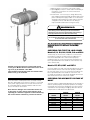
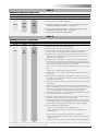
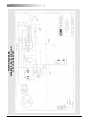
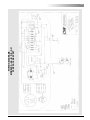
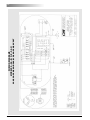
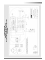
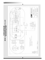
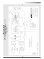
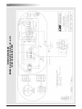
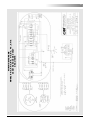
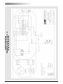
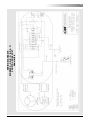
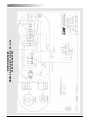
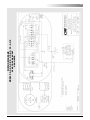
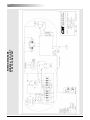
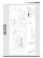
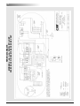
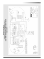
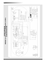
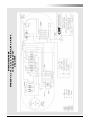
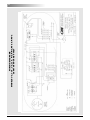
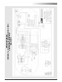
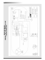
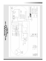
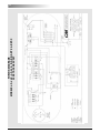
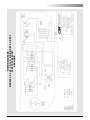
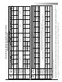
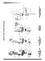
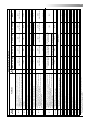
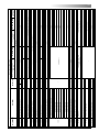
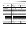
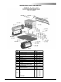
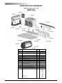
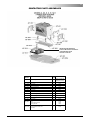
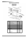
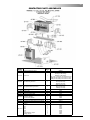
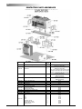
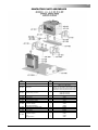
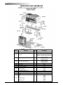
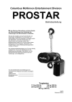
WIRING DIAGRAMS
MODELS J-2, JJ-2, L-2, LL-2, R-2, RR-2, RT-2 & RRT-2
380/415/460-3-50/60 VOLT
CSA UNITS
43
WIRING DIAGRAMS
MODELS J, JJ, L, LL, R, RR, RT & RRT
550/575-3-50/60 VOLT
44
WIRING DIAGRAMS
MODELS J, JJ, L, LL, R, RR, RT& RRT
550/575-3-50/60 VOLT
CSA UNITS
45
WIRING DIAGRAMS
MODELS J-2, JJ-2, L-2, LL-2, R-2, RR-2, RT-2 & RRT-2
550/575-3-50/60 VOLT
46
WIRING DIAGRAMS
MODELS J-2, JJ-2, L-2, LL-2, R-2, RR-2, RT-2 & RRT-2
550/575-3-50/60 VOLT
CSA UNITS
47
48
ASSEMBLY INSTRUCTIONS
HOOK OR LUG SUSPENSION
Models E, H, R, RR, E-2, H-2, R-2 and RR-2.
Arrows Must Be
Aligned As
Shown
Assemble the dead end bolt and block through the suspension adapter as shown in Figure 19.
Liftwheel
627-302
Underside of
Bolt Head
Intermediate
Pinion 627-325
5 3/16
(132 mm)
Models R & RR
Missing Tooth in
Liftwheel Spline
Missing Tooth Space
in Liftwheel Gear
Spline
Liftwheel Gear
627-303
Dead End Bolt
Figure 20. Non-Circular Gearing
FASTENERS
Dead End Block
Figure 19. Hook Suspension
WEATHERPROOF HOIST
Check to see that the control station, gasket, neoprene
grommet, cover gaskets, motor housing and gear housing
gaskets are in good condition and in correct position when
reassembling.
GEARING
Models JJ, LL, RR, JJ-2, LL-2, RR-2, RRT and RRT-2 have a
special Liftwheel Gear (627-303) and Intermediate Pinion
(627-325).
If the gear train in these hoists is disassembled, the following
steps must be observed in order to properly orient the three
parts when reassembling:
1. Assemble liftwheel gear to liftwheel
NOTE: These parts have their splines keyed in such a
way that they will go together only one way. See Figure
20.
2. To install the intermediate pinion, align the arrows that are
stamped on the pinion and liftwheel gear so they point
toward each other.
3. Check operation of gear train by rotating the pinion four
(4) complete revolutions; liftwheel gear will turn one (1)
complete revolution and the arrows will again be aligned
as shown. If the arrows do not align or there is binding
between the gear teeth, repeat the above steps.
4. For gearing lubrication instructions, see page 15
Models A thru H-2 tighten motor housing screws (627-108)
to where they have a minimum breakaway torque of 48
pound inch and the brake attaching screws (627-253) have
50 pound inch (5.649 Nm) minimum breakaway torque.
Models J thru RRT-2 tighten limit switch attaching screws
(627-220), brake attaching screws (627-253) and hexagonal brake stud (627-265) to where they have a minimum
breakaway torque of 50 pound inch (5.649 Nm). The liftwheel gear nut (627-305) should be tighten to a seating
torque of 85 pound feet (115 Nm).
LOWER HOOK BLOCK PIN
When removing or installing the lower hook block pin (627764), care must be taken so as to prevent damaging the
pin and/or hook block. These pins are tapered groove pins
and as a result, they can only be removed in one direction.
To remove the pin, a V-Block, drift and hammer (or slow
acting press) are required. The drift should be the same
diameter as the pin (5/16” (7.94 mm) diameter for Models
A, A-2, AA, AA-2, B, B-2, C, C-2, F and F-2; and 3/8” diameter (9.52 mm) for Models J, J-2, JJ, JJ-2, L, L-2, LL and
LL-2), and it should be placed at the small end of the pin.
The small end of the pin is the end opposite the end on
which the 3 grooves are visible. Place the hook block in the
V-Block and drive the pin out using the drift and a hammer
or slow acting press.
To re-install the pin, the parts must be arranged the same
as they were when the pin was removed. To do this, use
the small end of the pin as a gage. First check the holes in
the hook block body and determine which holes is the
largest. Place the hook block body in the V-Block with the
larger hole on top. Next, check each end of the hole in the
lower chain block (627-775) and determine which end is
the largest. Place the chain in the slot of the chain and
insert the chain block, with the large hole on top, into the
hook body. Align the holes in the hook block body with the
49
hole in the chain block and insert the small end if the pin in
the hole. Push the pin in by hand until it stops and then use a
hammer or slow acting press to drive the pin into position so
that the end of the pin is flush with the outside surface of the
hook body.
L
! WARNING
Use of improper lower hook chain block pin as well as improper installation of this pin can cause the pin to break and allow
the load to fall.
TO AVOID INJURY AND PROPERTY DAMAGE:
Use only CM supplied, special high strength lower hook chain
block pin to attach the chain to the lower hook block and
install the pin as directed above.
REMOVAL AND INSTALLATION OF
LOAD CHAIN
L
! WARNING
Improper installation (reeving) of the load chain can result in a
dropped load.
TO AVOID INJURY:
Vertify use of proper size and type of hoist load chain for
specific hoist.
Install load chain properly as indicated below.
USE ONLY CM STAR (#) GRADE LOAD
CHAIN AND CM REPLACEMENT PARTS.
USE OF OTHER CHAIN AND PARTS MAY
BE DANGEROUS AND VOIDS FACTORY
WARRANTY.
L
! WARNING
USE OF COMMERCIAL OR OTHER MANUFACTURERS’ CHAIN
AND PARTS TO REPAIR CM HOISTS MAY CAUSE LOAD
LOSS.
TO AVOID INJURY:
Use only CM supplied replacement load chain and parts. Chain
and parts may look alike, but CM chain and parts are made of
specific material or processed to achieve specific properties.
NOTE: When installing load chain in Models E, H, R,
RR, E-2, H-2, R-2 and RR-2 by either of the
“starter chain” methods, two loose end connecting links (627-743) must be used.
Hoist load chain can be installed by any one of several methods. The first method is recommended when replacing
severely worn load chain and requires disassembling the
hoist. Method 2 does not require hoist disassembly, whereas
Method 3 requires only partial disassembly.
Method #1
a) Disconnect hoist from power supply.
b) Remove back frame cover and disengage the limit
switch guide plate from the traveling nuts, see page
16 or 17.
c) Detach loose end of load chain from hoist frame, see
Figure 7. Also on single reeved models, detach the
lower hook block from the load chain. On double
reeved models E, H, R, RR, E-2, H-2, R-2, and RR-2,
unfasten the dead end side of the load chain. On
triple reeved Models RT, RRT, RT-2 and RRT-2, detach
the load chain from the lower hook block.
d) Continue to disassemble the hoist and inspect the liftwheel, chain guides, motor housing and gear housing
which if worn or damaged could cause early failure of
the new chain. Parts can be easily identified by referring to pages 51 thru 85.
e) If the liftwheel pockets, in particular the ends, are
worn or scored excessively, replace the liftwheel. If
chain guides and housing are worn or cracked, these
parts should be replaced.
f) Reassemble hoist with the new load chain inserted
over the liftwheel. Position chain with the weld on
upstanding links away from liftwheel and leave only
one foot of chain hanging free on loose end side.
Make sure the last chain link is an upstanding link. On
double reeved models, make sure that the new load
chain has an even number of links. On triple reeved
models, make sure that the new chain has an odd
number of links. This will prevent twist in chain.
To simplify handling when reassembling the hoist, a
short undamaged piece of the old chain may be used
as a “starter chain”. Position this piece of chain in
exactly the same manner as explained above for the
“new chain”, and complete the reassembly of the
hoist.
g) Attach the loose end link to chain and connect it to
the hoist frame with the loose end screw, washer and
lockwasher, see Figure 7. BE SURE THERE IS NO
TWIST.
If a starter chain is used, the loose end link (two links
required for double reeved models) can serve as a
temporary coupling link to connect together the starter
chain in the hoist and the new load chain to be
installed. Then, under power, reeve the new load
chain through the liftwheel area, replacing the starter
chain in unit. Run enough chain through to attach
loose end link to hoist frame.
Caution: For double reeved models, be sure to
disconnect one of the loose end links from load
chain before attaching to hoist frame.
h) For single reeved models, attach the hook block to
load chain.
i) For double reeved models, run the hoist (UP) until
only 3 feet (.9 M) in chain remains on dead end side.
This will minmize the chance of introducing a twist
between hook block and hoist.
Allow the chain to hang free to remove twists.
Using a wire as a starter, insert the chain, flat link first,
into lower hook block (upstanding links will have weld
toward sheave) and pull through. Insert last link into
slot in dead end block making sure that no twist
exists in the reeving at any point.
Assemble dead end pin, washer and cotter pin as
shown in Figure 7.
j) For triple reeved models, run the hoist (UP) until only
4 feet (1.2 M) of chain remains on the dead end side.
This will minimize the chance of introducing a twist
between the hook block and hoist.
Allow the chain to hang free to remove twists.
Using a wire as a starter, insert the chain, upstanding
link first, into lower hook block (upstanding links will
50
have welds toward sheave) and pull through. Using a
wire as a starter, insert the chain, upstanding link first,
into the outboard cloverleaf of the hanger. Make sure
there are no twists between the hook block and then
pull the chain through. In the sheave hanger, the
upstanding links will have the welds toward the
sheaves. Run the chain down to the hook block and
making sure there are no twists between the sheave
hanger and the hook block, insert the end of the chain
into the recess in the top of the hook block. Slide the
dead end screw, with flat sides vertical, through the
hole in the top of the hook block. Place the lockwasher
and nut on the threaded end of the dead end screw.
Use an Allen wrench to hold the head of the dead end
screw stationary and rotate the nut to tighten. To properly tighten the nut, apply a torque of 45 (61Nm) to 55
pound feet (74.6 Nm) while holding the head of the
dead end screw stationary.
Also, when tightening this dead end screw, it should
be held firmly in position and torqued from the nut end
to avoid damaging the screw and/or chain.
k) Adjust limit switches as described on pages 16 and
17. If the new chain is longer than the old, check to be
sure limit switch will allow for new length of lift. In the
event maximum adjustment does not allow entire
length of lift, check with CM for modification necessary.
Do not allow hook block to hit hoist or allow load chain
to become taut between loose end screw and frame
or else serious damage will result. If hook should
inadvertently hit the hoist-the hoist frames, load chain
and hook block should be inspected for damage
before further use.
L
! WARNING
Cutting Chain Can Produce Flying Particles.
TO AVOID INJURY:
Wear Eye Protection.
Provide A Shield Over Chain To Prevent Flying Particles.
Fig 22. Cutting Chain with a Bolt Cutter
TESTING
Before using, all altered, repaired or used hoists that have
not been operated for the previous 12 months shall be tested
by the user for proper operation. First, test the unit without a
load and then with a light load of 50 pounds (22.7 kg) times
the number of load supporting parts of load chain to be sure
that the hoist operates properly and that the brake holds the
load when the control is released. Next test with a load of
*125% of rated capacity. In addition, hoists in which load
sustaining parts have been replaced should be tested with
*125% of rated capacity by or under the direction of an
appointed person and written report prepared for record purposes. After this test, check that the Protector functions. If the
Protector permits lifting a load in excess of 200% of rated
metric load, it should be replaced.
NOTE: For additional information on inspection and
testing, refer to Code B30.16 “Overhead Hoist”
obtainable from ASME Order Department, 22 Law
Drive, Box 2300, Fairfield, NJ 07007-2300, U.S.A.
*If the Protector prevents lifting of a load of 125% of rated
capacity, reduce load to rated capacity.
Method #2
Treat the old load chain in hoist as a “starter chain” and
proceed with Steps 1a, b, c and f thru k above.
Method #3
a)
b)
c)
d)
e)
First proceed with Steps 1a, b, c above.
Then, carefully run the load chain out of the hoist.
Disconnect hoist from power supply.
Remove the electric brake assembly.
Rotate the brake hub by hand, at the same time feeding the load chain through the liftwheel area with hoist
upside down or by using a wire to pull the load chain
up onto the liftwheel. Position the chain on the liftwheel
as explained in Step 1f.
f) Refer to Steps 1g thru k above to complete the
installation.
ORDERING INSTRUCTIONS
The following information must accompany all correspondence orders for replacement parts:
1. Hoist Model Number from identification plate
2. Serial number of the hoist stamped below identification plate.
3. Voltage, phase, hertz from identification plate.
4. Length of lift.,
5. Key number of part from parts list.
6. Number of parts required.
7. Part name from parts list.
8. Part number from the parts list.
If trolley replacement parts are ordered, also include the type
and capacity of trolley.
CUTTING CHAINS
CM HoistAloy® load chain is hardened and it is difficult to cut.
The following methods are recommemded when cutting a
length of new chain from stock or cutting off worn chain.
1. Use a 7” (177.8 mm) minimum diameter by 1/8” (3.175
mm) thick abrasive wheel (or type recommended by
wheel supplier) that will clear adjacent links.
2. Use a bolt cutter (Figure 22) similar to the H.K. Porter
No. 0590MTC with special cutter jaws for cutting hard-
Note: When ordering replacement parts, it is recommended that consideration be given to the need
for also ordering such items as gaskets, fasteners, insulators, etc. These items may be damaged
or lost during the disassembly or just unfit for
future use because of deterioration from age or
L
! WARNING
Using “Commerical” or other manufacturer’s parts to repair
the CM Lodestar Hoists may cause load loss.
TO AVOID INJURY:
Use only CM supplied replacement parts. Parts may look alike
but CM parts are made of specific materials or processed to
achieve specific properties.
service.
ened chain (1” (25.4 mm)long cutting edge).
Part
Name
Stator
Part
Name
Electric Brake
Assembly Complete
Brake Coil
627-415
Key
No.
627-250
627-259
Attaching
Screws
*3/4 Motor
Assembly
Motor End
Plate
Models and Voltages
AA, C, F and H
A-2, B-2 and E-2
AA-2, C-2, F-2 and H-2
51517
51517
286007
(60 HZ)
286009
(50 HZ)
287007
(60 HZ)
286008
(50 HZ)
287006
286004
51518
27659
287009
286004
51520
27658
286006
(60 HZ)
286011
(50 HZ)
286010
(50 HZ)
286001
287002
(60 HZ)
286001
51517
51517
51518
27684
287001
286000
27654
27681
27681
287005
286000
51520
27683
286011
286002
51518
27659
287004
286003
27654
51519
27655
287010
286003
51520
27683
287003
286003
51518
27684
287004
286003
27654
51519
27656
287010
286003
51520
27683
51511
35647
51515
35649
51512
35648
51516
36688
51511
35647
51513
35622
51515
35649
51512
35648
51514
35623
87377
367028
367001
**367040K
87377
367003
87377
367014
87336
367023
367009
87377
367015
87336
367018
87336
367020
87336
367021
87336
367022
87336
51516
36688
Note: CM Extraction Tool Code 27163 Can Be Ordered Separately for Removal of Individual Wires from Motor or Wiring Harness Plugs.
Note: Except as indicated above, Electric Brake Assemblies, Brake Coils, Rotor Assemblies and Stators listed under “230/460” are also suitable for operation on 220/380-3-50 or
220/415-3-50. Those listed under “230” are also suitable for operation on 220-3-50 and those listed under “460” are also suitable for operation on 380-3-50 or 415-3-50.
**367050K
87336
35688 (18 Teeth and 13 Teeth Hub) for Models J, J-2, JJ, & JJ-2
35687 (12 Teeth and 13 Teeth Hub) for Models L, L-2, LL, LL-2, R, R-2, RR, RR-2, RT, Rt-2, RRT, and RRT-2
51510
35646
87377
51510
35646
Models and Voltages
J, L, R, AND RT
JJ, LL, RR, ANDRRT
J-2, L-2, 4-2, AND RT-2
JJ-2, LL-2, RR-2, AND RRT-2
115-1-60 230-1-50/60 230/460 575-3-60 230/460 575-3-60 230-3-60 460-3-60 575-3-60 230-3-60 460-3-60 575-3-60
286005
286005
27653
27656
27656
110-1-50 220-1-50
110-1-50 220-1-50
230/460 575-3-60
230/460 575-3-60 230-3-60 460-3-60 575-3-60 230-3-60 460-3-60 575-3-60
115-1-60 230-1-60
115-1-60 230-1-60
A, B, and E
*3/4 Motor includes Stator, Rotor and Shaft Assembly and End Bell.
**Motor Kit Includes ‘B1’ & ‘B2’ Brake Jumpers.
627-415A
627-415
627-411
thru 627-315,
as applicable)
627-310 (items 627-311
Drive Shaft &
Pinion S/A
Rotor & Shaft
Assembly
thru 627-315,
as applicable)
627-413
627-250
Electric Brake
Assembly Complete
627-259 Brake Coil
Drive Shaft &
Pinion S/A
627-310 (items 627-311
Key
No.
Part Numbers for Brake Coils, Brake Assemblies, Rotors,
Stators and Attaching Screws
51
52
Part Number for Packaged Lubricants
Used in the Lodestar Electric Chain Hoists
(Refer to page 15 for Lubrication Instructions)
Lubricant
Usage
Type of
Lubricant
Hoist Gears
Spline on end
of Drive Shafts
Grease
(Special)
Oil-Graphite
Mixture
Load Chain
Oil
Limit Switch
Shaft Threads
Lower Hook
Thrust Bearing
*Oil
*Oil
Part Numbers and
Packaged Quantity
of Lubricants
28605 for ½ lb. Can
28616 for 1 lb. Can
28617 for 4 lb. Can
40628 for 1 Pint Can
28608 for 1 Pint Can
28619 for 1 Gal. Can
“3 in 1” or Light Machine
Oil-obtain locally
Heavy Machine Oilobtain locally
*These oils are not furnished by CM in Packaged Quantities.
When ordering lubricants, specify the type of lubricant, part number and packaged quantity required.
Touch-up Paints for Lodestar Electric Chain Hoists and Series 635 Low Headroom Trolleys:
1. Hoist. Order *(1) case (12-12 oz. Aerosol Cans) of Orange Touch-Up paint Part Number 84190.
2. Trolley. Order *(1) case (12-12 oz. Aerosol Cans) of Black Touch-Up paint Part Number 84189.
*Touch-up paints are only available in case quantities.
Note: When painting Hoists or Trolleys, also order warning labels, identification labels, etc. that may be coated during painting.
Notes
53
Notes
Models A, A-2, AA, AA-2,
B, B-2, C, C-2, E, E-2,
F, F-2, H, & H-2
HOIST FRAME COMPONENTS GENERAL LAYOUT
Models J, J-2, JJ, JJ-2,
L, L-2, LL, LL-2, R, R-2,
RR, RR-2, RT, RT-2, RRT, & RRT-2
54
Back Frame Cover Screw
Back Frame Seal Screw
Capacity Label
Series Label
Electrical Warning Label
627-245
627-445
627-685
627-820
Weatherproof Units
Standard Units
Back Frame Cover Screw Lockwasher
CSA Cover w/drain slot (Orange)
Black
Orange
Back Frame Cover
Black
Orange
Back Frame
Gear Housing Gasket
Black
Orange
627+132
627-131
627-130
627-125
627-124
627-120
Motor Housing Spacer Gasket
627-115B
Gear Housing
Motor Housing Wire Way Gasket
Black
Orange
Motor Housing
CSA Covers w/drain slot (Orange)
Black
Orange
627-115A
627-115
627-110
Motor Housing Cover
Weatherproof Units
Standard Units
Motor Housing Cover Screw Lockwashers
Motor Housing Cover Screws
627-109
Motor Cover and Back Frame Cover Alignment Pins
627-107
Motor Housing Cover Gasket
(Weatherproof Units Only)
Back Frame Cover Gasket
(Weatherproof Units Only)
Part Name
627-108
627-102
627-101
Key
Number
1
1
As Req’d
As Req’d
1
1
1
1
1
1
1
1
2
2
8
1
1
E, E-2, H, H-2
27238
36840
982623
968752 (4 Required)
982251 (4 Required)
982226 (4 Required)
36022 (Also order 627-445)
35200 (1/2 Ton), 35201 (1 Ton),
35202 (2 Ton), 35203 (3 Ton)
24842
35090
35707
36008C (Also order 627-445)
35095
35627
35620
---
---
36604
--29001
36078
24008B
29002
36023
36076
36071
982251
982226
987553
983784
35840
35845
RT, RT-2, RRT,
RRT-2
24008C
36008B (Also order 627-445)
Part Number
R, R-2, RR, RR-2
----
87325 (3 Required)
982251 (3 Required)
982226 (3 Required)
27097
28009C
Models
J, J-2, JJ, JJ-2, L,
L-2, LL, LL-12
27276 (1/8 Ton), 27277 (1/4 Ton),
27278 (1/2 Ton), 27279 (1 Ton)
28009B
27625 (Includes 627-123 & 627-211)
27618 (Includes 627-123 & 627-211)
27747
28672
28669
28996
28993
27028B
27028C
27095
27059 (Includes 627-402,446, 447)
27597 (Includes 627-402, 446 & 447)
982251
982226
987397
---
27848
27847
No. A, A-2, AA, AA-2, B,
Req’d B-2, C, C-2, F, F-2
Hoist Frame Components
55
627-700
COMPLETE SWIVEL HOOK
SUSPENSION
627-710
COMPLETE RIGID HOOK
SUSPENSION
627-720
COMPLETE LUG
SUSPENSION
LODESTAR HOIST UPPER SUSPENSION
TRIPLE REEVED SUSPENSION
& SHEAVE HANGER
56
Cloverleaf Plate & Attaching Screws
Sheave Stud 2/wsher, Slotted Nut, Seat and Retainer Pin
Sheave Hanger
Sheave Hanger Bearing
Upper Sheave
Suspension Lug
Shackle w/Pin and Retainer Rings
Suspension Lug Pin w/Retainer Pins
Bearing Retainer Ring
Dead End Bolt (Special Alloy)
Dead End Block
Dead End Pin
Dead End Pin Cotter Pin
Dead End Pin Washer
Special High Strength Bolts, Grade 6 or better required for attachment
Suspension Lug
For Series 635 Low Headroom Trolley
For Series 635 Motor Driven Trolley
Suspension Lug
(Includes 627-702, 627-703, 627-706 & 627-711 & 627-721A for Models A, A-2, AA,
AA-2, B, B-2, C, C-2, F, F02, J, J-2, JJ, JJ-2, L, L-2, LL, & LL-2
(Includes 627-702, 627-703, 627-706, 627-711, 627-721A, 627-830 & 627-823 thru 627836 for Models E, E-2, H, H-2, R, R-2, RR & RR-2)
(Includes 627-702, 627-703, 627-7-6, 627-711, 627-728, 627-729 and 627-730 for
Models RT, RT-2, RRT & RRT-2
Upper Hook or Suspension Lug Collar (For Rigid Hook and Lug Suspension)
Latch Kit
Lug Suspension
(Includes 627-701 thru 627-703, 627-706 & 627-711 for Models A, A-2, AA, AA-2,
B, B-2, C, C-2, F, F-2, J, J02, JJ, JJ-2, L, L-2, LL, & LL-2)
(Includes 627-702, 627-703, 627-706, 627-711, 627-733, 627-830 & 627-833, thru
627-836 for Models E, E02, H, H-2, R, R-2, RR & R-2.
(Includes 627-702, 627-703, 627-706, 627-711, 627-728, 627-729 thru 627-730
for Models RT, RT-2, RRT & RRT-2
Rigid Hook Suspension
Upper Hook
Latch Type
Latchlok Type
Suspension Adapter Screw
Suspension Adapter
Upper Hook Washer (Swivel Hook Suspension Only)
Upper Hook Collar Nut (Swivel Hook Suspension Only)
Upper Hook or Suspension Lug Pin (Special Alloy Steel)
Specify for Rigid or Swivel Type Suspension
(Includes 627-701 thru 627-706 for Models A, A-2, AA, AA-2, B, B-2, C, C-2, F, F-2, J,
J-2, JJ, JJ-2, L, L-2, LL, & LL-2.)
(iIncludes 627-701 thru 627-706, 627-830 & 627-833 thru 627-836 for Models E, E-2, H,
H-2, R, R-2, RR & R-2)
(Includes 627-701 thru 627-703, 627-705 & 627-7-6 for Models RT, RT-2, RRT & RRT-2)
Swivel Hook Suspension
Part Name
*Contact Factory for Part Numbers of Suspensions with Latchlok Type Hooks
**For Swivel Hook Nut, Part Number is 36352
627-723
627-724
627-725
627-726
627-727
627-728
627-729
627-730
627-731
627-830
627-833
627-834
627-835
627--836
627-721B
627-721A
627-720
627-711
627-716
627-710
627-706
627-702
627-703
627-704
627-705
627-701
627-700
Key
Number
27003B
27786
27350
27805
1
1
1
1
1
1
1
1
1
1
1
28643
1
1
1
1
1
27370
45662
27455
27454
89508
27397
82320
988330
987878
27452
2993 for Series 635
Motor Driven Trolley
27450
2992 for Series 635 Motor
Driven Trolley
2778 for Series 635 Low
Headroom Trolley
27361
45661
*2789
(Latch Type Hook)
45941
27013
45930
45385
28602
28697
2793
(Latch Type Hook)
E, E-2, H, H-2
35458
45662
*3651
(Latch Type Hook)
35740B
45930
35042
983763 (Rigid)
983764 (Swivel)
36678
35617
3661
(Latch Type Hook)
Models
J, J-2, JJ, JJ-2,
L, L-2, LL, LL-2
Part Number
35957
35418
82314
988330
987877
35457
35459
Contact Factory
35457
3668
35479
45663
*3658
(Latch Type Hook)
36680
35588
35741B
45918
35041
983761 (Rigid)
983762 (Swivel)
35616
3660
(Latch Type Hook)
R, R-2 RR, RR-2
35456
3679 for Series 635
Motor Driven Trolley
2779 for Series 635 3677 for Series 635 Low
Low Headroom Trolley
Headroom Trolley
27529
*2788
(Latch Type Hook)
28689
2792
(Latch Type Hook)
1
1
No.
A, A-2, AA, AA-2,
Req’d B,B-2, C, C-2, F, F-2
Upper Suspension Components
C246
C247
36011
88429
36350
Order Complete Suspension
C248
40740
9561
**36360
45663
*9559
(Latch Type Hook)
983762
Order Complete Suspension
--36352
36694
35613
9557
(Latch Type Hook)
RT, RT-2, RRT,
RRT-2
57
58
LODESTAR LOWER HOOK BLOCK ASSEMBLY
59
Lower Hook Block Assembly
Key
Number
Part Name
A, A-2, AA,
No. AA-2, B, B-2, E, E-2,
H, H-2
Req’d
C-2, F, F-2
RT, RT-2,
J, J-2, JJ,
R , R-2,
RRT,
JJ-2, L, LRR, RR-2 RRT-2,
2, LL, LL-2
Part Number
627-716 Latch Kit (specify no. req’d)
Hook Block Screws with Nuts and
627-722
Lockwasher (2 Each)
627-732 Dead End Screw with Nut and Lockwasher
1
627-760 Lower Hook Block Assembly
1
**28683
---
35651
627-763 Lower Hook Body
1
45401B
---
35370
627-764 Lower Hook Chain Block Pin
1
45943
---
35790
627-770 Lower Hook Block Assembly
1
-
*28665
---
Lower Hook with Latch:
Latch Type Hook
1
28686
28687
35611
Latchlok Type Hook
1
28604
28603
28604
All Other Hook Types
1
627-771
-
45661
45662
45662
45663
45663
---
1
C245
---
C249
---
36607
-----
*35645
*36606
35612
36606
36681
***
Contact Factory
627-772 Lower Hook Thrust Bearing
1
88485
88478
88485
88505
88505
627-773 Lower Hook Collar
1
---
27359
---
35478
---
627-774 Lower Hook Pin
1
983772
45941
983772
45946
983762
627-775 Lower Hook Chain Block
1
28007
---
35026
627-776 Lower Hook Nut
1
982526
---
982526
627-777 Lower Hook Block Washer
1
945921
627-833 Dead End Block
1
---
27397
---
35418
---
627-834 Dead End Pin
1
---
82320
---
82314
---
627-835 Dead End Pin Cotter Pin
1
---
988330
---
988330
---
627-836 Dead End Pin Washer
1
---
987878
---
987877
---
627-837 Contact Block
1
---
---
---
36764
---
627-860 Lower Hook Block Assembly-Complete
1
-
**28685-
---
**0000277B
*36607
627-861 Hook Block Sheave
1
-
27017
00000274
36351
627-862 Hook Block Sheave Bearing
2
-
88429
83674
83670
627-863 Hook Block (Order in Pairs)
2
-
27048
36032
36010
627-864 Hook Block Screw-Long
2
-
982066
982374
627-865 Hook Block Screw-Short
1
-
986191
982370
627-866 Hook Block Screw L.W.
3
-
940802
940830
627-867 Hook Block Screw Nut
3
-
982514
982445
-----
945921
*Contact CM for Part Number of Suspension with Latchlok Type Hook.
**Latch Type Hook. Contact CM for Part Number of Lower Hook and Body with Latchlok Type Hook.
***For Swivel Hook Nut, Part Number is 36352.
36352
---
Control and
Power Cords
LODESTAR HOIST CONTROL END COMPONENTS
Models J, J-2, JJ,
JJ-2, L, L-2, LL,
LL-2, R, R-2, RR,
RR-2, RT, Rt-2,
RRT, RRT-2
Models A, A-2, AA,
B, B-2, C, C-2, E, E-2,
F, F-2, H, H-2
60
Back Frame Attaching Screw Lockwasher
Back Frame Attaching Screw
Back Frame Attaching Screw Lockwasher
Back Frame Attaching Screw
Back Frame Attaching Screw Lockwasher
627-127A
627-128
627-128A
627-129
627-129A
Hex Brake Stud Lockwasher
627-272
940830
---
---
---
---
---
See page 72-77
57753
982708 (2 Req’d)
---
---
---
---
---
982226
927835
987827
945840
See Separate Parts List on Page 62-63
982688
982232
36674
954807
35831
982709 (1 Req’d)
945851 (1 Req’d)
31636 (See Separate Parts List on Page 64)
36656 (See Separate Parts List on Page 64)
940830
36641 (See Separate Parts List on Page 64)
---
987322 (2” lg)
982226
1
Power Cord Attaching Screw Lockwasher
Instruction Tag
Power Cord
Control Cord Assembly
Terminal Strip
Terminal Strip End Clamp
Terminal Strip Mounting Bracket
Terminal Strip Mounting Screw
Terminal Strip Mtg. Screw Lockwasher
Terminal Strip Mtg. Bracket Screws
Terminal Strip Mtg. Bracket Screw Lockwasher
Terminal Strip Mtg. Bracket Screw Nut
627-687
627-1017
627-1018
627-1019
627-1050
627-1051
627-1065
627-1066
627-1067
627-1068
627-1069
627-1070
2
2
2
2
2
1
2
4
1
1
1
---
29924 (Single Phase Units)
29925 (220/230-1-50/60 Units)
27589 (Three Phase)
39452*
39460*
29042 (Single Phase Units)
29430 (Three Phase Units)
988141*
987873*
958805*
957855*
951726*
29012 All Other Units
---
RT, RT-2,
RRT, RRT-2
31639* (220/230-1-50/60 & 110 volt Single Phase w/Transformers)
See Separate parts list on Pages 86-88
29271 (Dual Voltage), 927992 (Single Voltage)
--987827
3
982514
1
Contactor Mounting Plate Stud Nut
Power Cord Attaching Screw
627-686
-----
982226
627-605
3
Contactor Mounting Plate Stud Lockwasher
29079
110/115 Volt Primary w/24 Volt Secondary with
Thermal Cutout for CSA
627-604
29078
110/115 Volt Primary w/48 Volt Secondary with
Thermal Cutout for CSA
27836
29074
110/115 Volt Primary w/24 Volt Secondary
Contactor Mounting Plate Stud
29073
110/115 Volt Primary w/48 Volt Secondary
3
29076
29077
29075
220/230 Volt Primary w/48 Volt Secondary w/th
Thermal Cutout for CSA
220/230 Volt Primary w/24 Volt Secondary w/th
Thermal Cutout for CSA
29072
220/230 Volt Primary w/24 Volt Secondary
220/230 Volt Primary w/115 Volt Secondary w/th
Thermal Cutout for CSA
29070
1
940802
982698 (1 3/4” lg.)
---
---
---
---
---
---
982226 (2 Req’d)
940802
982682
---
---
---
---
---
R, R-2, RR, RR-2
29071
4
982699
Part Name
J, J-2, JJ, JJ-2,2 L, L-2,
LL, LL-2
627-602
627-530
2
1
1
1
1
1
1
1
2
-
-
1
1
1
2
2
2
2
4
940837
E, E-2,H, H-2
220/230 Volt Primary w/48 Volt Secondary
3
3
1
No. Req’d
Models
220/230 Volt Primary w/115 Volt Secondary
Transformer:
Transformer Attaching Screw
Hex Brake Stud
627-265
627-528
Hex Brake Stud Spring Washer
627-264
Control Cord Attaching Screw Lockwasher
Hex Brake Stud Spring
627-263
627-473
Brake Stud Nut
627-257
Control Cord Attaching Screw
Brake Attaching Screw
Control Cord Attaching Screw Washer
Brake Attaching Screw Lockwasher
627-252
627-253
627-471
Electric Brake Assembly - Complete
627-250
627-472
Limit Switch Kit
Rotatable Limits
627-222
627-220
Back Frame Attaching Screw
627-127
Limit Switch Shaft & Gear Kit
Back Frame Expansion Plug
Part Name
627-123
Key Number
A, A-2, AA, AA-2, B, B-2, C, C2, F, F-2
Control End Components
61
62
Lodestar Hoist Brake Components
Models A, A-2, AA,
B, B-2, C, C-2, E, E2, F, F-2, H, H-2
Models J, J-2, JJ,
JJ-2, L, L-2, LL, LL-2,
R, R-2, RR, RR-2, RT,
RT-2, RRT, RRT-2
63
Brake Components
Models
Key
Number
Part Name
No.
Req’d
A, A-2, AA, AA-2, B, J, J-2, JJ, JJ-2, L, L-2, LL,
B-2, C, C-2, F, F-2, LL-2, R, R-2, RR, RR-2, RT,
H, H-2
RT-2, RRT, RRT-2
Part number
627-251
Brake Base Plate and Studs
1
28668
35643
627-254
Brake Intermediate Plate
1
27091
(For Models AA, AA-2, C,
C-2, F, F-2, H & H-2 only)
35069
627-255
Brake Spring
2
27751
(Color Coded Blue)
35716
(Color Coded Yellow for Models J,
J-2, L-2, R, R-2, RT and RT-2)
35717
(Color Coded Green for Models JJ,
JJ-2, LL, LL-2, RR, RR-2, RRT and
RRT-2)
627-256
Brake Field Sub-Assembly
1
28677
(Includes 627-262)
35629
627-257
Brake Stud Nut
2
627-258
Brake Coil Retainer Strap
1
627-259
Brake Coil
1
627-260
Brake Armature Assembly
1
28678
35600
(Includes 627-262)
-
27677
(1 Req’d for Models A, A-2,
B, B-2, E, E-2)
(2 req’d for Models AA, AA2, C, C-2, F, F-2, H, H-2)
35632
(2 Req’d)
627-261
Brake Friction Disc
345840
57753
35704
See Separate Listing on Page 51
64
LODESTAR HOIST LIMIT SWITCH COMPONENTS
Models A, A-2, AA, AA-2,
B, B-2, C, C-2, E, E-2, F,
F-2, H, H-2
Models J, J-2, JJ, JJ-2, L,
L-2, LL, LL-2, R, R-2, RR,
RR-2, RT, RT-2, RRT, RRT-2
65
Limit Switch Components
Models
Key
Number
Part Name
A, A-2, AA, AA-2, B, J, J-2, JJ, JJ-2, L, L-2, LL,
No. B-2, C,C-2, E, E-2, F, LL-2, R, R-2, RR, RR-2, RT,
Req’d
F-2, H, H-2
RT-2, RRT, RRT-2
Part Number
Limit Switch Shaft and Gear Kit
627-220
27561
36641
27749
36656
27714
35753
70399
36373
27307
36317
Limit Switch Shaft (64 thread)
27251
36321
Travel Nut (44 thread)
70053
70053
36318
36318
36319
36319
Rotatable Limit Switch
627-220A Limit Switch Gear
1
1
Limit Switch Shaft (44 thread)
627-220B Limit Switch Shaft (56 thread)
627-220C Travel Nut (56 thread)
1
2
Travel Nut (64 thread)
627-220D Spring
1
28712
35703
627-220E Limit Switch Bearing
2
---
35751
627-220F Mounting Screws
2
---
983656
Limit Switch Kit: Three Phase
627-222
31631
1
All Others
627-231 Limit Switch Bracket Sub-Assembly
31636
31631
1
27502
36644
66
LODESTAR HOIST GEARING COMPONENTS
Models A, A-2, AA, AA-2,
B, B-2, C, C-2, E, E-2, F,
F-2, H & H-2.
Models J, JJ, JJ-2, L, LL,
LL-2, R, RR, RR-2, RT,
RT-2, RRT & RRT-2.
67
Gearing Components
Models
Key
Number
Part Name
A, A-2, AA, AA-2, B, B- J, J-2, JJ, JJ-2, L, L-2, LL,
No.
Req’d 2, C, C-2, E, E-2, F, F- LL-2, R, R-2, RR, RR-2, RT,
2, H, H-2
RT-2, RRT, RRT-2
Part Number
627-119
Gear Housing Plug
1
627-122
Gear Housing Attaching Screw
4
Gear Housing Attaching Screw Lockwasher
4
627-122A
935495
28830
982682
940802
940830
27010 (47 teeth) Models A, A-2, C
35009 (79 teeth) Models J, J-2, L, L-2, R,
& C-2
R-2, RT & RT-2
28380 (39 teeth) Models AA &
35639 (60 teeth) Models JJ, JJ-2, LL, LL-2,
AA-2
RR, RR-2, RRt & RRT-2
27009 (56 teeth) Models B, B-2, E,
E-2, F, F-2, H & H-2
627-303
Liftwheel Gear
1
627-304
Liftwheel Gear Snap Ring
1
27767
---
627-305
Liftwheel Gear Nut
1
---
35773
627-306
Liftwheel Gear Nut Washer
1
---
986576
627-307
Liftwheel Bearing-Gear End
1
88429
82002
627-310
Drive Shaft and Pinion Sub Assembly
(Includes items 627-311 thru 627-315 as
applicable)
1
27654 (5-43/64” lg. shaft length)
35688 (18 teeth pinion & 13 teeth hub)
Models AA, AA-2, C, C-2, F, F-2, H
Models J, J--2, JJ & JJ-2
& H-2
35687 (12 teeth pinion & 15 teeth hub)
27653 (5 15/64” lg shat length)
Models L, L-2, LL, LL-2, R, R-2, RR, RR-2,
Models A, A-2, B, B-2, E & E-2
R, RT, RT-2, RRT & RRT-2
C204 (Models AA, AA-2, C, C-2, F,
35357 (18 teeth) Models J, J-2, JJ & JJ2
F-2, H & H-2)
35356 (12 teeth) Models L, L-2, LL, LL-2,
C203 (Models A, A-2, B, B-2, E &
R, R-2, RR, RR-2, RT, RT-2, RRT & RRT-2
E-2)
627-311
Drive Shaft and Pinion
1
627-312
Drive Shaft and Pinion Bearing
1
627-313
Drive Shaft and Pinion Bearing Spacer
82009
83691
1
27710
---
35744
627-314
Brake Hub
1
27852 (1 1/2 lg.) for Models AA,
AA-2, C, C-2, F, F-2, H & H-2
27851 (2 1/32 lg) for Models A,
A-2, B, B-2, E & E-2
627-315
Brake Hub Snap Ring
1
27765
35766
627-321
Intermediate Gear and Pinion Bearing
Outboard End
1
82009
88437
627-322
Limit Switch Drive Pinion
1
27712
---
627-323
Intermediate Gear Snap Ring
1
627-325
Intermediate Pinion
1
627-326
Intermediate Gear and Pinion Bearing
Inboard End
1
88440
Order (1) bearing 83670 and (1) Shaft
Adapter 24350)
1
28694 (for Models A, A-2, B, B-2,
E & E-2)
28693 (for Models AA & AA-2)
28695 (for Models C, C-2, F, F-2,
H & H-2)
36668 (for Models J & J-2)
36669 (for Models JJ & JJ-2)
36670 (for Models L, L-2, R, R-2, RT &
RT-2)
36671 (for Models LL, LL-2, RR, RR-2,
RRT & RRT-2)
1
2876 (for Models A & A-2)
3601 (for Models J & J--2)
2877 (for Models AA & AA-2)
3602 (for Models JJ & JJ-2)
2878 (for Models B, B-2, E & E-2) 3603 (for Models L, L-2, R, R-2 RT & RT-2)
2879 (for Models C & C-2)
3604 (for Models LL, LL-2, RR, RR-2 RRT
2880 (for Models F, F-2, H & H-2)
& RRT-2)
627-327
Lodestar Protector
627-328
Lodestar Protect Kit
(Includes item 627-124, 627-321, 627322, 627-323, 627-325 & 627-327 for
Models A, A-2, AA, AA-2, B, B-2, C, C-2,
C-2, E, E-2, F, F-2, H & H-2
(Includes items 627-124, 627-321, 627323, 627-325 & 627-327 for Models J, J-2,
L, L-2, R, R-2, RT & RT-2.
(Includes items 627-124, 627-323 & 627327 for Models JJ, JJ-2, LL, LL-2, RR, RR2, RRT & RRT-2
27765
35763
28624 (14 teeth) Models A, A-2, C
35351 (10 teeth) Models J, J-2, L, L-2, R,
& C-2
R-2, RT & RT-2
28625 (22 teeth) Models AA &
35420 (15 teeth) Models JJ, JJ-2, LL, LL-2,
AA-2
RR, RR-2, RRT & RRT-2
28623 (8teeth) Models B, B-2, E,
E-2, F, F-2, H, & H-2
68
LODESTAR HOIST LIFTWHEEL COMPONENTS
Models A, A-2, AA, AA-2,
B, B-2, C, C-2, F, F-2,
E, E-2, H, H-2
Models J, J-2, JJ, JJ-2, L, L-2,
LL, LL-2, R, R-2, RR, RR-2, RT,
RT-2, RRT, RRT-2
69
Liftwheel Components
Key
Number
Part Name
Models
A, A-2, AA,
J, J-2, JJ,
AA-2, B,
E, E-2,
R, R-2,
RT, RT-2,
No.
JJ-2, L, L-2,
RR, RR-2 RRT, RRT-2
Req’d B-2, C, C-2, H, H-2
LL, LL-2
F, F-2
Part Number
627-112 Suspension Adapter Anchor
2
---
35066
35015
627-116 Loose End Nut
1
82638
82639
627-117 Suspension Adapter Nut
2
927755
935791
627-118 Chain Guide
1
27008
35018
627-302 Liftwheel
1
27360
35421
627-307 Liftwheel Bearing-Gear End
1
88429
82002
627-308 Liftwheel Bearing-Motor End
1
88429
83669
627-740 Loose End Screw
1
927764
987210
627-741 Loose End Screw Lockwasher
1
982226
945851
627-742 Loose End Screw Washer
1
954802
954807
627-743 Loose End Link
1
27351
35367
85889
85979
85944
85949
85915
85916
Stainless Steel
85952
n/a
Zinc Phosphate
85965
85966
Load Chain (Specify Qty Required)
Burnished in Oil
Zinc
627-750
Niclad
627-837 Contact Block
627-1030
Dead End Block Hole Plug
(For use on Entertainment/Black
Units Only
As
Req’d.
1
---
---
---
36764
---
1
27223
---
---
35291
---
70
LODESTAR HOIST MOTOR END COMPONENTS
Models A, A-2, AA,
AA-2, B, B-2, C, C-2,
E, E-2, F, F-2, H, H-2
Models J, J-2, JJ,
JJ-2, L, L-2, LL, LL-2,
R, R-2, RR, RR-2, RT,
RT-2, RRT, RRT-2
71
Motor End Components
Key
Number
Part Name
A, A-2, AA, AA-2, B,
J, J-2, JJ, JJ-2, L, L-2, LL,
No.
B-2, C, C-2, E, E-2, F, LL-2, R, R-2, RR, RR-2, RT,
Req’d
F-2, H, H-2
RT-2, RRT, RRT-2
Part Number
627-113 Identification Plate
1
627-411 Motor Attaching Screw
4
627-412 Motor Attaching Screw Lockwasher
4
627-413 Rotor and Shaft Sub Assembly
1
See Pg. 51
1
1
1
983541
---
36023
627-416 Motor Shaft Bearing - Inboard End
1
82003
82004
627-417 Motor Shaft Bearing Snap Ring-Inboard End
627-439 Solid State Reversing Switch
627-440 Switch Clamp
2
1
1
27790
27257 (115/230-1-50/60 Units)
27295
35764
35499 (115/230-1-50/60 Units)
27275
627-441 Switch Clamp Screw
1
627-446 Rotor Wave Washer
627-447 Rotor Bearing Spacer
627-528 Transformer Attaching Screws
Transformer & Bracket Mounting Assembly
1
1
2
627-414 Stator Pin
627-415 Stator
627-415A Motor End Plate
Contact Factory
---
See Pg. 51
982226
----See Pg. 51
982873
27292
27291
--Contact Factory
982688
115 Volt Primary with 48 Volt Secondary code 29847
115 Volt Primary with 24 Volt Secondary code 29849
V1 Single Phase Units
110/115-1-50/60
*Units w/Transformer
115 Volt Primary with 48 Volt Secondary w/Thermal Cutout for CSA use
code 29848
115 Volt Primary with 24 Volt Secondary w/Thermal Cutout for CSA use
code 28999
220/230 Volt Primary with 115 Volt Secondary code 27771
220/230 Volt Primary with 48 Volt Secondary code 28850
220/230 Volt Primary with 24 Volt Secondary code 27780
V1 Single Phase Units
220/230-1-50/60
627-530
1
220/230 Volt Primary with 115 Volt Secondary w/Thermal Cutout for CSA
use code 27778
220/230 Volt Primary with 48 Volt Secondary w/Thermal Cutout for CSA
use code 27777
220/230 Volt Primary with 24 Volt Secondary w/Thermal Cutout for CSA
use code 28980
230/460 Volt Primary with 115 Volt Secondary code 27771
230/460 Volt Primary with 48 Volt Secondary code 28850
230/460 Volt Primary with 24 Volt Secondary code 27780
230/460 Volt Primary with 115 Volt Secondary w/Thermal Cutout for CSA
use code 27778
230/460 Volt Primary with 48 Volt Secondary w/Thermal Cutout for CSA
use code 27777
230/460 Volt Primary with 24 Volt Secondary w/Thermal Cutout for CSA
use code 28980
550/575 Volt Primary with 115 Volt Secondary w/Thermal Cutout for CSA
use code 27792
V1 Three Phase Units
*All Three Phase Voltages
550/575 Volt Primary with 48 Volt Secondary w/Thermal Cutout for CSA
use code 28798
550/575 Volt Primary with 24 Volt Secondary w/Thermal Cutout for CSA
use code 28796
627-599 Contactor Mounting Plate Screw
3
---
983656
627-820 Electrical Warning Label
1
24842
627-873 Chain Label
1
928894
72
CONTACTOR PLATE ASSEMBLIES
Key
Number
Part Name
No.
Req’d
Part Number
27716
627-418
Capacitor
1
627-439
Solid State Reversing Switch
1
27257
627-650
Hoist Reversing Contactor
1
28553 (115 Volt Coil)
627-1001 Contactor Mounting Plate
1
31633
627-1050 Terminal Strip
3
29014
627-1051 Terminal Strip End Clamp
1
29015
627-1052 Din Rail Mounting Bracket
1
29312
627-1053 Din Rail Mounting Bracket Screw
2
982686
627-1054 Din Rail Mounting Bracket Screw Lockwasher
2
987873
2
27910
627-1058 Insulating Capacitor Cap
1
29910
627-1059 Insulating Solid State Reversing Switch Cap
1
27925
4
982696
1
1
1
1
1
1
1
1
1
29911
29912
29913
29914
27156
29915
29916
29047
29926
627-1057
627-1060
Capacitor Mounting Bracket or
Solid State Reversing Switch Mounting Bracket
Capacitor Mounting Bracket or
Solid State Reversing Switch Mounting Bracket Screw
Jumpers:
R5
R6
R7
R8
627-1061
R14
B1
B2
Bridge
Wiring Harness
73
CONTACTOR PLATE ASSEMBLIES
Key
Number
Part Name
No.
Req’d
Part Number
27716
627-418
Capacitor
1
627-439
Solid State Reversing Switch
1
27257
627-650
Hoist Reversing Contactor
1
28545 (48 Volt Coil)
28552 (24 Volt Coil)
627-1001
Contactor Mounting Plate
1
31633
1
20940
627-1003A Ground Label
627-1050
Terminal Strip
3
29014
627-1051
Terminal Strip End Clamp
1
29015
627-1052
Din Rail Mounting Bracket
1
29312
627-1053
Din Rail Mounting Bracket Screw
2
982686
627-1054
Din Rail Mounting Bracket Screw Lockwasher
2
987873
627-1055
Ground Screw
1
987827
627-1057
Capacitor Mounting Bracket or
Solid State Reversing Switch Mounting Bracket
2
27910
627-1058
Insulating Capacitor Cap
1
29910
627-1059
Insulating Solid State Reversing Switch Cap
1
27925
627-1060
Capacitor Mounting Bracket or
Solid State Reversing Switch Mounting Bracket Screw
4
982696
627-1061
Jumpers:
R5
R6
R7
R8
R14
B1
B2
G-Y
Jumper Assembly
Wiring Harness
1
1
1
1
1
1
1
1
1
1
29911
29912
29913
29914
27156
29915
29916
27189
29929
29927
74
CONTACTOR PLATE ASSEMBLIES
Key
Number
627-418
627-439
Part Name
Capacitor
Solid State Reversing Switch
No.
Req’d
1
Part Number
27716
1
27257
627-650
Hoist Reversing Contactor
1
28553 (110 Volt Coil)
28545 (48 Volt Coil)
28552 (24 Volt Coil)
627-1001
Contactor Mounting Plate
1
31633
1
4
20940
29014
29015
627-1003A Ground Label
627-1050 Terminal Strip
627-1051
Terminal Strip End Clamp
1
627-1052
Din Rail Mounting Bracket
1
29312
627-1053
Din Rail Mounting Bracket Screw
2
982686
627-1054
Din Rail Mounting Bracket Screw Lockwasher
2
987873
627-1055
Ground Screw
1
987827
627-1057
Capacitor Mounting Bracket or
Solid State Reversing Switch Mounting Bracket
2
27910
627-1058
Insulating Capacitor Cap
1
29910
627-1059
Insulating Solid State Reversing Switch Cap
1
27925
627-1060
Capacitor Mounting Bracket or
Solid State Reversing Switch Mounting Bracket Screw
4
982696
627-1061
Jumpers:
R5
R6
R7
R8
R14
B1
B2
Bridge
Contactor Jumper
G-Y
Wiring Harness
1
1
1
1
1
1
1
1
1
1
1
29911
29912
29913
29914
27156
29915
29916
27047
51547
27189
29928
75
CONTACTOR PLATE ASSEMBLIES
*CM Terminal Pin Extraction
Tool Can Be Ordered To Remove
Individual Wires From
Harness Connector.
Key
Number
Part Name
No.
Req’d
Part Number
627-650
Hoist Reversing Contactor
1
24799 (110 Volt Coil
24797 (48 Volt Coil)
28860 (24 Volt Coil)
627-1001
Contactor Mounting Plate
1
31633
627-1003A Ground Label
1
20940
627-1012
Voltage Change Board Mounting Screw
1
987862
627-1013
Voltage Change Board
1
27672
627-1014
Voltage Change Board Insulator
1
27685
627-1050
Terminal Strip
1
29014
627-1051
Terminal Strip End Clamp
2
29015
627-1052
Din Rail Mounting Bracket
1
29312
627-1053
Din Rail Mounting Bracket Screw
2
982686
627-1054
Din Rail Mounting Bracket Screw Lockwasher
2
987873
627-1055
Ground Screw
1
987827
627-1061
Jumper:
G-Y
Motor Wiring Harness
Wiring Harness
1
1
1
27189
27603
29801
*627-1063
CM Terminal Pin Extraction Tool
(Not Shown)
1
27163
76
CONTACTOR PLATE ASSEMBLIES
Key
Number
Part Name
No.
Req’d
Part Number
627-650
Hoist Reversing Contactor
1
28553 (115 Volt Coil)
24797 (48 Volt Coil)
28860 (24 Volt Coil)
627-800
Hoist Speed Selecting Contactor
1
28870 (115 Volt Coil)
28871 (48 Volt Coil)
28878 (24 Volt Coil)
627-1001
Contactor Mounting Plate
1
31633
627-1003A
Ground Label
1
20940
627-1050
Terminal Strip
1
29014
627-1051
Terminal Strip End Clamp
2
29015
627-1052
Din Rail Mounting Bracket
1
29312
627-1053
Din Rail Mounting Bracket Screw
2
982686
627-1054
Din Rail Mounting Bracket Screw Lockwasher
2
987873
627-1055
Ground Screw
1
987827
627-1061
Jumpers:
R10
R13
B1
B2
Contactor Jumper
Contactor Jumper
G-Y
Wiring Harness
1
1
1
1
2
2
1
1
27609
27610
29915
29916
51845
51847
27189
29802
77
CONTACTOR PLATE ASSEMBLIES
Key
Number
Part Name
No.
Req’d
Part Number
627-650
Hoist Reversing Contactor
1
24799(115 Volt Coil)
24797 (48 Volt Coil)
28860 (24 Volt Coil)
627-1001
Contactor Mounting Plate
1
31633
627-1003A
Ground Label
1
20940
627-1050
Terminal Strip
1
29014
627-1051
Terminal Strip End Clamp
2
29015
627-1052
Din Rail Mounting Bracket
1
29312
627-1053
Din Rail Mounting Bracket Screw
2
982686
627-1054
Din Rail Mounting Bracket Screw Lockwasher
2
987873
627-1055
Ground Screw
1
987827
627-1061
Jumpers:
B1
B2
Contactor Jumper
G-Y
Wiring Harness
1
1
1
1
1
29915
29916
51847
27189
27160
78
CONTACTOR PLATE ASSEMBLIES
Key
Number
627-418
Start Capacitor
No.
Req’d
1
627-418A
Run Capacitor
1
627-423
Start/Run Capacitor Mounting Clamp
2
35268
627-424
Mounting Clamp Screw
6
982873
627-650
Hoist Reversing Contactor
1
27142 (115 Volt Coil)
27138 (48 Volt Coil)
27139 (24 Volt Coil)
627-1001
Contactor Mounting Plate
1
29013
Ground Label
1
20940
627-1051
Terminal Strip End Clamp
2
29015
627-1052
Din Rail Mounting Bracket
1
29009
627-1053
Din Rail Mounting Bracket Screw
2
982686
627-1054
Din Rail Mounting Bracket Screw Lockwasher
Jumpers:
R2
R3
R4
R5
R10
Contactor Jumper
Wiring Harness
Rubber Insulating Boot
2
987873
1
1
1
1
1
1
1
1
29036
29037
29035
29038
29034
51845
29039
35285
627-1003A
627-1061
627-1062
Part Name
Part Number
35279
35278
79
CONTACTOR PLATE ASSEMBLIES
Key
Number
627-418
627-418A
627-423
627-424
Part Name
Start Capacitor
Run Capacitor
Start/Run Capacitor Mounting Clamp
Mounting Clamp Screw
No.
Req’d
1
1
2
6
Part Number
35279
35278
35268
982873
Hoist Reversing Contactor
1
27013 (115 Volt Coil)
27104 (48 Volt Coil)
27105 (24 Volt Coil)
Contactor Mounting Plate
Ground Label
Terminal Strip End Clamp
Din Rail Mounting Bracket
Din Rail Mounting Bracket Screw
Din Rail Mounting Bracket Screw Lockwasher
1
1
2
1
2
2
29013
20940
29015
29009
982686
987873
627-1061
Jumpers:
R2
R3
R4
R5
R9
R10
G-Y
Wiring Harness
1
1
1
1
1
1
1
1
29036
29037
29035
29038
29113
29034
27189
29044
627-1062
Rubber Insulating Boot
1
35285
627-650
627-1001
627-1003A
627-1051
627-1052
627-1053
627-1054
80
CONTACTOR PLATE ASSEMBLIES
*CM Terminal Pin Extraction
Tool Can Be Ordered To
Remove Individual Wires From
Motor/Harness Connector.
Key
Number
627-528
Part Name
Transformer Mounting Screw
No.
Req’d
2
Part Number
982688
627-530
Transformer
1
627-650
Hoist Reversing Contactor
1
Contactor Mounting Plate
Ground Label
Conversion Board Mounting Screw
Conversion Board
Conversion Board Insulator
Terminal Strip
Terminal Strip End Clamp
1
1
1
1
1
3
4
29734 (115 V Secondary)
29756 (48 V Secondary)
29809 (24 V Secondary)
29811 (115 V Secondary with Thermal Cutout)
29983 (48 V Secondary with Thermal Cutout)
29982 (24 V Secondary with Thermal Cutout)
24799 (115 Volt Coil)
24797 (48 Volt Coil)
28860 (24 Volt Coil)
29013
20940
987862
27672
27685
29014
29015
Din Rail Mounting Bracket
Contactor Bracket
Terminal Strip Bracket
1
1
29009
29008
Din Rail Mounting Bracket Screw
Din Rail Mounting Bracket Screw Lockwasher
Ground Screw
Jumpers:
Contactor Jumper
G-Y
Wiring Harness
Wiring Harness
4
4
1
982686
987873
987827
1
1
1
1
51847
27189
27102
29670
CM Terminal Pin Extraction Tool (Not Shown)
1
21763
627-1001
627-1003A
627-1012
627-1013
627-1014
627-1050
627-1051
627-1052
627-1053
627-1054
627-1055
627-1061
*627-1063
81
CONTACTOR PLATE ASSEMBLIES
Key
Part Name
Number
627-528 Transformer Mounting Screw
No.
Req’d
2
Part Number
982688
29734 (115 V Secondary)
29756 (48 V Secondary)
29809 (24 V Secondary)
29811 (115 V Secondary with Thermal Cutout)
29983 (48 V Secondary with Thermal Cutout)
29982 (24 V Secondary with Thermal Cutout)
627-530
Transformer
1
627-650
Hoist Reversing Contactor
1
24799 (115 Volt Coil)
24797 (48 Volt Coil)
28860 (24 Volt Coil)
627-800
Hoist Speed Selecting Contactor
1
28870 (115 Volt Coil)
28871 (48 Volt Coil)
28878 (24 volt Coil)
Contactor Mounting Plate
Ground Label
Terminal Strip
Terminal Strip End Clamp
Din Rail Mounting Bracket
Contactor Bracket
Terminal Strip Bracket
Din Rail Mounting Bracket Screw
Din Rail Mounting Bracket Screw Lockwasher
Ground Screw
Jumpers:
R4
R5
R7
R8
W5
G-Y
Speed Selector Jumper
Wiring Harness
1
1
3
4
29013
20940
29014
29015
1
1
4
4
1
29010
29008
982686
987873
987827
1
1
1
1
1
1
2
1
27652
27657
27760
27762
27736
27189
51845
27897
627-1001
627-1003A
627-1050
627-1051
627-1052
627-1053
627-1054
627-1055
627-1061
82
CONTACTOR PLATE ASSEMBLIES
Key Number
627-528
Part Name
Transformer Mounting Screw
No.
Req’d
2
Part Number
982688
627-530
Transformer
1
627-650
Hoist Reversing Contactor
1
627-800
Host Speed Selecting Contactor
1
Contactor Mounting Plate
Ground Label
Terminal Strip
Terminal Strip End Clamp
Din Rail Mounting Bracket
Contactor Bracket
Terminal Strip Bracket
Din Rail Mounting Bracket Screw
Din Rail Mounting Bracket Screw Lockwasher
Ground Screw
1
1
3
4
29734 (115 V Secondary)
29756 (48 V Secondary)
29809 (24 V Secondary)
29811 (115 V Secondary with Thermal Cutout)
29983 (48 V Secondary with Thermal Cutout)
29982 (24 V Secondary with Thermal Cutout)
24799 (115 Volt Coil)
24797 (48 Volt Coil)
28860 (24 Volt Coil)
28870 (115 Volt Coil)
28871 (48 Volt Coil)
28878 (24 Volt Coil)
29013
20940
29014
29015
1
1
4
4
1
29010
29008
982686
987873
987827
1
1
1
1
1
1
2
1
27652
27657
27736
27189
51847
51845
51845
29600
627-1001
627-1003A
627-1050
627-1051
627-1052
627-1053
627-1054
627-1055
627-1061
Jumpers:
R4
R5
W5
G-Y
Contactor Jumper
Terminal Strip Jumper
Speed Selector Jumper
Wiring Harness
83
CONTACTOR PLATE ASSEMBLIES
Key
Number
627-528
Part Name
Part Number
627-530
Transformer
1
627-650
Hoist Reversing Contactor
1
Contactor Mounting Plate
Ground Label
Terminal Strip
Terminal Strip End Clamp
Din Rail Mounting Bracket
Contactor Bracket
Terminal Strip Bracket
Din Rail Mounting Bracket Screw
Din Rail Mounting Bracket Screw Lockwasher
Ground Screw
1
1
1
4
982688
29807 (115 V Secondary)
29805 (115 V Secondary with Thermal Cutout)
29789 (48 V Secondary with Thermal Cutout)
29984 (24 V Secondary with Thermal Cutout)
24799 (115 Volt Coil)
24797 (48 Volt Coil)
28860 (24 Volt Coil)
29013
20940
29014
29015
1
1
4
4
1
29009
29008
982686
987873
987827
1
1
1
51847
27189
29601
627-1001
627-1003A
627-1050
627-1051
627-1052
627-1053
627-1054
627-1055
627-1061
Transformer Mounting Screw
No.
Req’d
2
Jumpers:
Contactor Jumper
G-Y
Wiring Harness
84
CONTACTOR PLATE ASSEMBLIES
Key
Number
627-528
Part Name
Transformer Mounting Screw
No.
Req’d
Part Number
2
982688
627-530
Transformer
1
29807 (115 V Secondary)
29805 (115 V Secondary with Thermal Cutout)
29789 (48 V Secondary with Thermal Cutout)
29984 (24 V Secondary with Thermal Cutout)
627-650
Hoist Reversing Contactor
1
24799 (115 Volt Coil)
24797 (48 Volt Coil)
28860 (24 Volt Coil)
627-800
Host Speed Selecting Contactor
1
28870 (115 Volt Coil)
28871 (48 Volt Coil)
28878 (24 Volt Coil)
627-1001
Contactor Mounting Plate
1
29013
1
20940
627-1003A Ground Label
627-1050
Terminal Strip
1
29014
627-1051
Terminal Strip End Clamp
4
29015
627-1052
Din Rail Mounting Bracket
Contactor Bracket
Terminal Strip Bracket
1
1
29009
29008
627-1053
Din Rail Mounting Bracket Screw
4
982686
627-1054
Din Rail Mounting Bracket Screw Lockwasher
4
987873
627-1055
Ground Screw
1
987827
627-1061
Jumpers:
R4
R5
W5
Contactor Jumper
Contactor Jumper
G-Y
Wiring Harness
1
1
1
2
1
1
1
27652
27657
27736
51845
51847
27189
29600
85
NOTES
86
LODESTAR HOIST CONTROL STATION
627-450 Complete Control Cord and Station Assembly
Single Spoeed Hoist Control Station
Single Speed Hoist Control Station
Key
Number
Part Name
No.
Req’d
Part Number
627-450 Control Cord and Station Assembly
1
627-451 Standard Control Cord Assembly
1
627-551 Control Station Grommet
1
29333 for 10’ Lift
29334 for 15’ Lift
29335 for 20’ Lift
29336 for 10’ Lift for CSA Units
29350 for 10’ Lift
29351 for 15’ Lift
29352 for 20’ Lift
29353 for 10’ Lift for CSA Units
58278
627-552 Control Station (Includes 627-551 thru 627-567)
1
58272
627-563 Control Station Hardware Kit w/gasket
1
58275
627-565 Control Station 1-speed Insert
1
58255
627-566 Control Station Warning Label Kit (Includes Exterior Labels)
1
58276
627-567 Contol Station Button Label Kit
1
58277
87
627-450 Complete Control Cord and Station Assembly
Two Speed Hoist Control Station
Key
Number
Part Name
No.
Req’d
Part Number
627-450 Control Cord and Station Assembly
1
627-451 Standard Control Cord Assembly
1
627-551 Control Station Grommet
1
29337 for 10’ Lift
29348 for 10’ Lift for CSA Units
29354 for 10’ Lift
29349 for 10’ Lift for CSA Units
58278
627-552 Control Station (Includes 627-551 thru 627-567)
1
58273
627-563 Control Station Hardware Kit w/gasket
1
58275
627-565 Control Station 2-speed Insert
1
58256
627-566 Control Station Warning Label Kit (Includes Exterior Labels)
1
58276
627-567 Contol Station Button Label Kit
1
58277
88
627-450 Complete Control Cord and Station Assembly
Four Directional Hoist Control Station
Four Directional Control Station
Key
Number
No.
Req’d
Code
627-451 Standard Control Cord Assembly
1
51708
627-551 Control Station Grommet
1
58278
627-552 Control Station (Includes 627-551 Thru 627-567)
Control Station Housing Kit
627-553
(Includes Housing, Boots, Collar, Gasket & Hardware)
627-563 Control Station Hardware Kit w/gasket
Control Station 1-Speed Insert
627-565
Control Station 2-Speed Insert
1
58220 CM
1
58288
1
1
1
58279
58255
58256
627-566 Control Station Warning Label Kit
1
58276
627-567 Contol Station Button Label Kit
1
58277
Part Name
89
NOTES
90
90
SERIES 635 LOW HEADROOM TROLLEY PARTS LIST
Figure 27. 1 and 2 Ton Series 635 Low Headroom Trolley Exploded View
Key No. Part Name
627-330 TrackWheel
627-336 TrackWheel Stud Nut
627-337 Suspension Bolt (Special
Alloy Special Alloy Steel Bolt)
*9 5/32” Long
**10¼” Long
†
10” Long
††
12 1/16” Long
627-338 Trolley Spacer Washers
* 0.165” Thick
**0.125” Thick
†
0.165” Thick
††
0.125” Thick
627-339 Suspension Bolt Nut
627-340 Suspension Bolt Nut
Cotter Pin
627-342 ***Side Frame, Plain Side,
w/o Trolley Guards
***Side Frame, Plain Side,
Trolley Guards
627-379 ***Side Frame, I.D., Plate
Side, w/o Trolley Guards
***Side Frame, I.D., Plate
Side, Trolley Guards
627-380 Load Bracket
* 3 7/16” Wide
**5 13/32” Wide
†
4 3/16” Wide
††
6 11/16” Wide
No. Req’d.
1 Ton 2 Ton
4
4
4
4
Part Number
1 Ton
2 Ton
35774
50762
982520 948804
2
2
-
2
2
35450
35407
-
35445
35414
40
38
4
4
32
38
4
4
35782
958822
35783
988039
948803 958818
988343 988368
2
2
35640
35654
2
2
35635
35636
2
2
35640
35654
2
2
35635
35636
1
1
35019
35024
-
35033
-
35043
Key No. Part Name
627-381 Vertical Load Bar Pin
(Special Alloy Steel Pin)
*2 11/16” Long
**2 7/8” Long
†
3 3/4” Long
627-382 Vertical Load Bar Pin Screw
627-383
627-384
627-386
627-389
627-395
* ½” Long
**1¼” Long
†
3/4” Long
††
1½” Long
Vertical Load Bar Pin
Screw L.W.
TrackWheel Stud Nut L.W.
Identification Label
TrackWheel Washer
Warning Label
No. Req’d.
1 Ton 2 Ton
1
1
Part Number
1 Ton
2 Ton
35371
1
35413
35400
1
1
1
982383
982386
982433
987209
983548 983547
4
1
1
4
1
1
1
987923 987924
36916
36917
987903
936984 936984
* These items are for the 1-Ton Trolley for operation on 2.66" thru 5.64" flange
widths.
** These items are for the 1-Ton Trolley for operation on over 5.64" thru 7.00" flange
widths.
*** If side frame is equipped with spacer block, contact factory.
†
These items are for the 2-Ton Trolley for operation on 3.33" thru 6.00" flange
widths.
††
These items are for the 2-Ton Trolley for operation on over 6.00" thru 8.25" flange
widths.
91
Figure 28. 3 Ton Series 635 Low Headroom Trolley Exploded View
Key No.
No.
Part Name
Required
Part Number
635-1
2
Side Frame-Plain Side
36696 For 4.0” Thru 5.63” Flange Widths, 36629 For Over 5.63” Thru 7-¼”
(Does Not Include Wheels)
Flange Widths. If Frame is Equipped With Trolley Guards, Contact Factory.
TrackWheel Plain
39002
TrackWheel Bearing
82113
TrackWheel Stud
36361
TrackWheel Washer-Steel
81014
TrackWheel Washer-Oilite
82046
TrackWheel Stud Lockwasher
987926
TrackWheel Stud Nut
988155
Load Bracket (Specify Width)
36012 (4-13/16” Wide), 36021 (6-7/16” Wide)
635-4
635-6
635-7
635-9
635-10
635-11
635-12
635-13
4
4
4
4
4
4
4
1
635-17
2
Suspension Bolt
(Specify Length)
635-18
30
Spacer Washer
635-19
4
Suspension Bolt Nut
945835
635-20
4
Suspension Bolt Cotter Pin
988382
635-22
1
Warning Label
936984
635-30
1
Identification Label
936829
36367 (10-31/32” Long) For 4.00” Thru 5.63” Flange Widths
36380 (13-3/32” Long) For Over 5.63” Thru 7.25” Flange Widths
If Bolt Length is Over 13-3/32”, Contact Factory
936827
®
Note: When ordering parts, always furnish hoist model and serial number, motor horsepower,
voltage, phase, frequency and rated capacity of hoist on which the parts are to be used.
For the location of the nearest CM Master Parts Depot, see the list located on the inside front cover.
LIMITATION OF WARRANTIES, REMEDIES AND DAMAGES
THE WARRANTY STATED BELOW IS GIVEN IN PLACE OF ALL
OTHER WARRANTIES, EXPRESS OR IMPLIED, OF MERCHANTABILITY, FITNESS FOR A PARTICULAR PURPOSE, OR
OTHERWISE, NO PROMISE OR AFFIRMATION OF FACT MADE
BY ANY AGENT OR REPRESENTATIVE OF SELLER SHALL
CONSTITUTE A WARRANTY BY SELLER OR GIVE RISE TO
ANY LIABILITY OR OBLIGATION.
Seller warrants that on the date of delivery to carrier the goods are
free from defects in workmanship and materials.
SELLER’S SOLE OBLIGATION IN THE EVENT OF BREACH OF
WARRANTY OR CONTRACT OR FOR NEGLIGENCE OR
OTHERWISE WITH RESPECT TO GOODS SOLD SHALL BE
EXCLUSIVELY LIMITED TO REPAIR OR REPLACEMENT, F.O.B.
SELLER’S POINT OF SHIPMENT, OF ANY PARTS WHICH SELLER DETERMINES TO HAVE BEEN DEFECTIVE or if Seller determines that such repair or replacement is not feasible, to a refund of
the purchase price upon return of the goods to Seller.
the use of the goods if, prior to such damage, injury or loss, such
goods are (1) damaged or misused following Seller’s delivery to carrier; (2) not maintained, inspected, or used in compliance with
applicable law and Seller’s written instructions and recommendations; or (3) installed, repaired, altered or modified without compliance with such law, instructions or recommendations.
UNDER NO CIRCUMSTANCES SHALL SELLER BE LIABLE FOR
INCIDENTAL OR CONSEQUENTIAL DAMAGES AS THOSE
TERMS ARE DEFINED IN SECTION 2-715 OF THE UNIFORM
COMMERCIAL CODE.
Any action against Seller for breach of warranty, negligence or otherwise, must be commenced within one year after such cause of
action occurs.
INDEMNIFICATION AND SAFE OPERATION
Buyer shall comply with and require its employees to comply with
directions set forth in instructions and manuals furnished by Seller
and shall use and require its employees to follow such instructions
and manuals and to use reasonable care in the use and maintenance of the goods. Buyer shall not remove or permit anyone to
remove any warning or instruction signs on the goods. In the event
of personal injury or damage to property or business arising from
the use of the goods, Buyer shall within 48 hours thereafter give
Seller written notice of such injury or damage. Buyer shall cooperate
with Seller in investigating any such injury or damage and in the
defense of any claims arising therefrom.
NO CLAIM AGAINST SELLER FOR ANY DEFECT IN THE GOODS
SHALL BE VALID OR ENFORCEABLE UNLESS BUYER’S WRITTEN NOTICE THEREOF IS RECEIVED BY SELLER WITHIN ONE
YEAR FROM THE DATE OF SHIPMENT.
Seller shall not be liable for any damage, injury or loss arising out of
If Buyer fails to comply with this section or if any injury or damage is
caused, in whole or in part, by Buyer’s failure to comply with applicable federal or state safety requirements, Buyer shall indemnify and
hold Seller harmless against any claims, loss or expense for injury
or damage arising from the use of the goods.
L
! WARNING
Alterations or modifications of equipment and use of nonfactory repair parts can lead to dangerous operation and
injury.
TO AVOID INJURY:
• Do not alter or modify equipment.
• Do use only CM replacement parts.
®
Columbus McKinnon Corporation
Industrial Products Division
140 John James Audubon Parkway
Amherst, New York 14228-1197
1-800-888-0985
Fax 716-689-5644
© 2008 Columbus McKinnon Corp.
Printed in USA