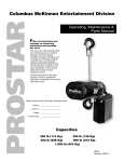
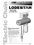
1
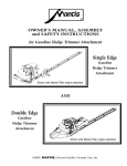
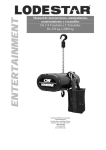
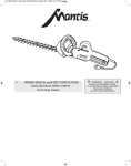
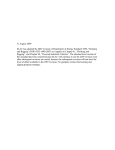
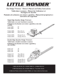
KEY
NO.
673-51
673-52
673-53
673-54
673-55
673-56
673-57
673-58
673-59
673-60
673-61
*673-62
673-63
673-64
673-65
673-66
673-67
673-68
673-69
673-70
673-71
*673-72
673-73
673-74
673-75
673-76
**673-77
NO.
REQ’D.
1
1
1
1
1
1
1
1
1
1
1
1
1
1
3
3
3
1
1
2
1
1
1
1
1
1
673-78
2
PART NAME
Hook Block Screw
Load Chain (Specify Length Req’d.)
End Ring
Capacity Label
I.D. Label
Warning Tag
Patent Label (no longer available order 673-55)
Load Limiter Label (Only for units
with Load Limiter)
Load Limiter (Optional)
Cam Washer
Anchor Sling
Lower Hook with latch (Latch type)
Lower Hook Washer
Lower Hook Nut
Lower Hook Nut Pin
Lower Hook Block Screw
Lower Hook Block Screw L.W.
Lower Hook Block Screw Nut
Reeving Caution Plate
Lower Sheave
Lower Hook Block
Upper Hook with latch (latch type)
Upper Hook Nut
Upper Hook Nut Pin
Hoist Hanger
Dead End Pin
Upper hook block assembly (includes
673-16,673-30 and 673-35)
Lock Pin
* If latchlok hook is required, part numbers are:
** If latchlok hook is required, contact Yale.
3/4 TON
40854
85839
73759
73901
7310 P
7309 P
73606
73340
PART NUMBER
1 1/2 TON
3 TON
40855
–
85847
40471
73751
73752
73903
73905
–
73763
7311 P
73316
7312 P
73607
Note: When ordering parts, always furnish rated load and serial number of hoist on which the parts are
to be used.
For the location of the nearest Yale Authorized Hoist Parts Depot, see inside front cover.
LIMITATION OF WARRANTIES, REMEDIES AND DAMAGES
THE WARRANTY STATED BELOW IS GIVEN IN PLACE OF ALL
OTHER WARRANTIES, EXPRESS OR IMPLIED, OF
MERCHANTABILITY, FITNESS FOR A PARTICULAR
PURPOSE, OR OTHERWISE, NO PROMISE OR AFFIRMATION
OF FACT MADE BY ANY AGENT OR REPRESENTATIVE OF
SELLER SHALL CONSTITUTE A WARRANTY BY SELLER OR
GIVE RISE TO ANY LIABILITY OR OBLIGATION.
–
40606
50454
40382
982335
940812
940830
945820
45757
40166
40689
40606
40382
982335
73324
40851
-
Seller warrants that on the date of delivery to carrier the goods
are free from defects in workmanship and materials.
SELLER’S SOLE OBLIGATION IN THE EVENT OF BREACH OF
WARRANTY OR CONTRACT OR FOR NEGLIGENCE OR
OTHERWISE WITH RESPECT TO GOODS SOLD SHALL BE
EXCLUSIVELY LIMITED TO REPAIR OR REPLACEMENT,
INDEMNIFICATION AND SAFE OPERATION
Buyer shall comply with and require its employees to comply with
directions set forth in instructions and manuals furnished by Seller
and shall use and require its employees to follow such
instructions and manuals and to use reasonable care in the use
and maintenance of the goods. Buyer shall not remove or permit
anyone to remove any warning or instruction signs on the goods.
In the event of personal injury or damage to property or business
arising from the use of the goods, Buyer shall within 48 hours
thereafter give Seller written notice of such injury or damage.
Buyer shall cooperate with Seller in investigating any such injury
or damage and in the defense of any claims arising therefrom.
Any action against Seller for breach of warranty, negligence or
If Buyer fails to comply with this section or if any injury or damage
NO CLAIM AGAINST SELLER FOR ANY DEFECT IN THE
GOODS SHALL BE VALID OR ENFORCEABLE UNLESS
BUYER’S WRITTEN NOTICE THEREOF IS RECEIVED BY
SELLER WITHIN ONE YEAR FROM THE DATE OF SHIPMENT.
Seller shall not be liable for any damage, injury or loss arising out
of the use of the goods if, prior to such damage, injury or loss,
such goods are (1) damaged or misused following Seller’s
delivery to carrier; (2) not maintained, inspected, or used in
compliance with applicable law and Seller’s written instructions
3/4 ton upper and lower hooks - 1001, 1 1/2 ton upper and lower hooks - 1002
and recommendations; or (3) installed, repaired, altered or
modified without compliance with such law, instructions or
recommendations.
UNDER NO CIRCUMSTANCES SHALL SELLER BE LIABLE
FOR INCIDENTAL OR CONSEQUENTIAL DAMAGES AS
THOSE TERMS ARE DEFINED IN SECTION 2-715 OF THE
UNIFORM COMMERCIAL CODE.
F.O.B. SELLER’S POINT OF SHIPMENT, OF ANY PARTS
WHICH SELLER DETERMINES TO HAVE BEEN DEFECTIVE or
if Seller determines that such repair or replacement is not
feasible, to a refund of the purchase price upon return of the
goods to Seller.
otherwise, must be commenced within one year after such cause
of action occurs.
3 ton lower hook - 1004, 3 ton upper hook - 1010
is caused, in whole or in part, by Buyer’s failure to comply with
applicable federal or state safety requirements, Buyer shall
indemnify and hold Seller harmless against any claims, loss or
expense for injury or damage arising from the use of the goods.
3 TON LOWER SHEAVE BEARING
JOURNALS AND SEAT FOR HOOK KNOB
(3/4 AND 1-1/2 TON)
TIP OF LEVER PLUNGER AND
THREADED END OF PINION SHAFT
INSIDE OF LEVER HEAD
GEARS, LIFTWHEEL SPLINE, NEEDLE
BEARINGS, PINION BUSHING, CAM AND
LOCK PINS, CAM SLOTS, AND I.D. OF CAM
THREADS OF PINION
LOAD CHAIN
TYPE OF
LUBRICANT
PART NUMBERS AND
PACKAGED QUANTITIES
OF LUBRICANTS
GREASE-GRAPHITE
MIXTURE
40626 (1 LB., .46 Kg. CAN)
DRY-LUBE OIL-
40628 (1 PT., .5L CAN)
GRAPHITE MIXTURE
GREASE
40630 (1 LB., .46 Kg. CAN)
GREASE
28610 (1 LB., .46 Kg. CAN)
28632 (4 LB., 1.8 Kg. CAN)
SPRAY DRY
LUBRICANT
OIL
O P E R AT E D
RS2
Lever Hoist
CHAIN HOIST
Follow all instructions and warnings for
inspecting, maintaining and operating this
hoist.
The use of any hoist presents some risk of personal
injury or property damage. That risk is greatly increased
if proper instructions and warnings are not followed.
Before using this hoist, each operator should become
thoroughly familiar with all warnings, instructions and
recommendations in this manual. Retain this
manual for future reference and use.
WARNING
ALTERATIONS OR MODIFICATIONS OF EQUIPMENT AND USE OF
NON-FACTORY REPAIR PARTS CAN LEAD TO DANGEROUS
OPERATION AND INJURY.
Forward this manual to operator.
Failure to operate equipment as directed in
manual may cause injury.
TO AVOID INJURY:
• DO NOT ALTER OR MODIFY EQUIPMENT
• DO USE ONLY FACTORY PROVIDED REPLACEMENT PARTS
Before installing hoist, fill in the
information below.
Model No. __________________
46698 (16 OZ. CAN)
28608 (1 PT., .5L CAN)
When ordering lubricants, specify the type of lubricant, part number and packaged quantity required.
Touch-up paint for the RS2:
*(1) case (12-12 oz. Aerosol Cans) of Yellow Touch-up Paint Part Number 40215.
*Touch-up paints are only available in case quantities.
NOTE: When painting the hoists, also order warning labels and
capacity labels that may be coating during painting.
M A N U A L LY L E V E R
Capacities: 3/4, 1-1/2, 3 ton
(750, 1500, 3000 kg.)
PART NUMBERS FOR PACKAGED LUBRICANTS USED IN THE RS2 LEVER HOISTS
(REFER TO PAGE 6 FOR LUBRICATION INSTRUCTIONS)
LUBRICANT
USAGE
MAINTENANCE &
PA R T S M A N U A L
7311 P
73342
O P E R AT I N G ,
Serial No. __________________
414 WEST BROADWAY AVENUE
MUSKEGON, MICHIGAN 49443
1-866-805-2962 • Fax: 1-800-742-
13
© 2001 Yale Hoist
SS-5/2001
Purchase Date ______________
414 WEST BROADWAY AVENUE
MUSKEGON, MICHIGAN 49443
Rated Load _________________
Printed in USA
73907 A
Manual No. Y673-A
YALE HOIST PARTS AND SERVICES AVAILABLE IN THE UNITED STATES.
As a Yale Hoist and Trolley user, you are assured of reliable repair and parts services
through a network of Authorized Parts Depots that are strategically located in the United
States. These facilities have been selected on the basis of their demonstrated ability to
handle all parts and repair requirements promptly and efficiently. To quickly obtain the
name of the Authorized Parts Depot located nearest you, call (866) 805-2962,
Fax (800) 742-9270.
NOTES
Load Limiter
(Optional)
Exploded View
RS2 Lever Hoist
WARNING
USING “COMMERCIAL” OR OTHER
MANUFACTURER’S PARTS TO REPAIR THE RS2
LEVER HOIST MAY CAUSE LOAD LOSS.
TO AVOID INJURY:
USE ONLY YALE SUPPLIED REPLACEMENT PARTS.
PARTS MAY LOOK ALIKE BUT YALE PARTS ARE
MADE OF SPECIFIC MATERIALS OR PROCESSED
TO ACHIEVE SPECIFIC PROPERTIES.
ORDERING INFORMATION
The following information must accompany all correspondence or repair parts orders:
1) Capacity
2) Serial Number - this is stamped on the frame
For parts orders also specify:
1) Quantity desired
2) Key number of part
3) Part Name
4) Part number of the part
When ordering replacement parts, consideration should be given to the need to replace other items,
(bushings, fasteners, etc.) and items that may be damaged or lost during disassembly or just unfit for future
use because of deterioration from age or service.
Parts should be ordered from Yale Master Parts Depots conveniently located throughout the United States.
Refer to the back of front cover of this manual to locate the Parts Depot nearest you.
i
11
12
SAFETY PRECAUTIONS
Each Yale RS2 Manually Lever Operated Hoist is built in accordance with the specifications contained herein and at
the time of manufacture complies with our interpretation of applicable sections of *ASME B30.21, *ANSI/ASME HST3M and the Occupational Safety and Health Act-1970.
The safety laws for elevators and for dumbwaiters specify construction details that are not incorporated in Yale
industrial hoists. We recommend the use of equipment that meets state and national safety codes for such use. Yale
Hoists cannot be responsible for applications other than those for which Yale equipment is recommended.
!
THIS SYMBOL POINTS OUT IMPORTANT SAFETY INSTRUCTIONS WHICH IF NOT FOLLOWED
COULD ENDANGER THE PERSONAL SAFETY AND/OR PROPERTY OF YOURSELF AND OTHERS.
READ AND FOLLOW ALL INSTRUCTIONS IN THIS MANUAL AND ANY PROVIDED WITH THE
EQUIPMENT BEFORE ATTEMPTING TO OPERATE YOUR YALE LEVER HOIST.
!
*Copies of these standards may be obtained from ASME Order Department, 22 Law Drive, Box 2300, Fairfield, NJ 07007-2300.
WARNING!
1.
2.
Improper operation of a hoist can create a potentially hazardous
situation which, if not avoided, could result in death or serious
injury. To avoid such a potentially hazardous situation, the
operator shall:
3.
4.
5.
6.
7.
8.
9.
10.
11.
12.
13.
14.
15.
16.
17.
18.
19.
20.
21.
22.
23.
24.
NOT operate a malfunctioning or unusually performing hoist.
NOT operate the hoist until you have thoroughly read and
understood this Operating, Maintenance and Parts Manual.
NOT operate a hoist which has been modified without the
manufacturer’s approval or certification to be in conformity with
applicable OSHA regulations.
NOT lift or pull more than rated load for the hoist.
NOT use damaged hoist or hoist that is Not working properly.
NOT use hoist with twisted, kinked, damaged, or worn load chain.
NOT operate with any lever extension (cheater bar).
NOT attempt to “free-chain” the hoist while a load is applied.
NOT use the hoist to lift, support, or transport people.
NOT lift loads over people and make sure all personnel remain
clear of the supported load.
NOT attempt to lengthen the load chain or repair damaged load
chain.
Protect the hoist’s load chain from weld splatter or other
damaging contaminants.
NOT operate hoist when it is restricted from forming a straight
line from hook to hook in the direction of loading.
NOT use load chain as a sling or wrap load chain around load.
NOT apply the load to the tip of the hook or to the hook latch.
NOT apply load unless load chain is properly seated in the chain
wheel(s) or sprocket(s).
NOT apply load if bearing prevents equal loading on all load
supporting chains.
NOT operate beyond the limits of the load chain travel.
NOT leave load supported by the hoist unattended unless
specific precautions have been taken.
NOT allow the chain or hook to be used as an electrical or
welding ground.
NOT allow the chain or hook to be touched by a live welding
electrode.
NOT remove or obscure the warnings on the hoist.
NOT operate a hoist which has Not been securely attached to a
suitable support.
NOT operate a hoist unless load slings or other approved single
attachments are properly sized and seated in the hook saddle.
25.
26.
27.
28.
29.
1.
NOT lift loads that are Not balanced and that the holding action is
Not secure, taking up slack carefully.
NOT operate a hoist unless all persons are and remain clear of
the supported load.
Report malfunctions or unusual performances of a hoist, after it
has been shut down until repaired.
NOT operate a hoist on which the safety placards or decals are
missing or illegible.
Be familiar with operating controls, procedures, and warnings.
CAUTION!
Improper operation of a hoist can create a potentially hazardous
situation which, if not avoided, could result in minor or moderate
injury. To avoid such a potentially hazardous situation, the
operator shall:
2.
3.
4.
5.
6.
7.
8.
9.
10.
11.
12.
13.
14.
15.
16.
Maintain a firm footing or be otherwise secured when operating
the hoist.
Check brake function by tensioning the hoist prior to each lift or
pulling function.
Use hook latches. Latches are to retain slings, chains, etc. under
slack conditions only.
Make sure the hook latches are closed and not supporting any
parts of the load.
Make sure the load is free to move and will clear all
obstructions.
Avoid swinging the load or hook.
Avoid lever “fly-back” by keeping a firm grip on the lever until
operating stroke is completed and the lever is at rest.
Inspect the hoist regularly, replace damaged or worn parts, and
keep appropriate records of maintenance.
Use the hoist manufacturer’s recommended parts when repairing
the unit.
Lubricate load chain per hoist manufacturer’s recommendations.
NOT use the hoist load limiting or warning device to measure
load.
NOT operate except with manual power.
NOT permit more than one operator to pull on lever at the same
time. More than one operator is likely to cause hoist overload.
NOT allow your attention to be diverted from operating the hoist.
NOT allow the hoist to be subjected to sharp contact with other
hoists, structures, or objects through misuse.
NOT adjust or repair the hoist unless qualified to perform such
adjustments or repairs.
ii
HOIST SAFETY IS UP TO YOU...
–DO NOT APPLY MORE THAN RATED LOAD.
1
CHOOSE THE RIGHT HOIST FOR THE JOB...
Choose a Yale Lever Hoist with a capacity
for the job. Know the capacities of your
hoists and the weight of your loads. Then
match them.
The application, the size and type of load,
the attachments to be used and the period
of use must also be taken into consideration
in selecting the right hoist for the job.
Remember the hoist was designed to ease
our burden and carelessness not only
endangers the operator, but in many cases,
a valuable load.
– DO NOT OPERATE DAMAGED OR MALFUNCTIONING UNIT.
– DO NOT OPERATE WITH TWISTED, KINKED OR DAMAGED
CHAIN.
2
INSPECT
Load chain should be properly lubricated.
All hoists should be visually inspected
before use, in addition to regular, periodic
maintenance inspections.
Inspect hoists for operational warning
notices and legibility.
Deficiencies should be noted and brought to
the attention of supervisors. Be sure
defective hoists are tagged and taken out of
service until repairs are made.
Under no circumstances should you operate
a malfunctioning hoist.
Check chain for gouged, twisted, distorted
links and foreign material. Do not operate
hoists with twisted, kinked or damaged
chain links.
Hooks that are bent, worn or whose
openings are enlarged beyond normal
throat opening should not be used. If latch
does not engage throat opening of hook,
hoist should be taken out service.
Chains should be checked for deposits of
foreign material which may be carried into
the hoist mechanism.
Check brake for evidence of slippage under
load.
– DO NOT PULL AT AN ANGLE. BE SURE LEVER HOIST AND
LOAD ARE IN A STRAIGHT LINE.
– DO NOT USE UNLESS FRAME AND CHAIN FORM A
STRAIGHT LINE BETWEEN HOOKS.
– DO NOT USE IF FRAME IS IN CONTACT WITH ANY OBJECT.
– DO NOT USE LOAD CHAIN AS A SLING.
– DO NOT USE AN EXTENSION ON THE LEVER.
3
USE HOIST PROPERLY
Be sure the hoist is solidly held in
the uppermost part of the support
hook arc.
Be sure the hoist and load are in a
straight line. Do not use unless
frame and chain form a straight
line between hooks.
Be sure load is hooked securely.
Do not tip load the hook. Do not
load hook latch. Hook latch is to
prevent detachment of load under
slack chain conditions only.
Do not operate with hoist frame
resting against any object. Apply
the load gently. Do not jerk it.
Never use an extension on the
lever! You’re dangerously
overloading the hoist if you exceed
the rated lever pull or if you have
to use a lever extension to lift or
pull a load.
– DO NOT LIFT PEOPLE OR LOADS OVER PEOPLE.
4
PRACTICE CAUTION ALWAYS
Do not lift co-workers with a Yale Lever
Hoist.
Make sure everyone is clear of the load
when you apply tension.
Do not remove or obscure operational
warning notices.
iii
5
OPERATOR SERVICE
CLEANING: Lever Hoists should be kept
clean and free of dust, dirt, moisture, etc.,
which will in any way affect the operation or
safety of the equipment.
LUBRICATION: Chain should be properly
lubricated.
AFTER REPAIRS: Carefully operate the
hoist before returning it to full service.
VIOLATION OF ANY OF THESE WARNINGS LISTED MAY RESULT SERIOUS PERSONAL INJURY TO THE
OPERATOR OR NEARBY PERSONNEL BY RELEASED LOAD OR BROKEN HOIST COMPONENTS.
SPECIFICATIONS
The Yale RS2 Lever Hoist is a highly versatile manually
lever operated chain hoist that can be used to efficiently pull,
lift, drag or stretch. Standard features of the hoist include:
• Alloy steel liftwheel to reduce chain wear.
• Hoistaloy load chain for long and dependable service.
• Grease lubricated, hardened, alloy steel gears for smooth
operation.
• Forged steel upper and lower latch type hooks.
• Patented, free-chaining mechanism for quick and easy
attachment to the load.
• Lightweight, aluminum frame, covers and lever.
• Ball or needle bearings at rotating points.
• Compact, yet rugged, design provides minimum
headroom and long trouble free service.
• Sealed automatic brake with two holding pawls for
positive load control.
• Short lever (12 inches-305 mm long on 3/4 ton unit, 163/4 inches-425 mm long on 1-1/2 and 3 ton units) for
operation in close quarters.
• Rocking and swivel upper hook (3/4 and 1-1/2 ton units)
• Backed by Yale’s life-time warranty.
®
Latchlok® Hooks
Latchlok hooks are available to replace the standard latch
type hooks. The unique design of the Latchlok hook assures
that it will stay locked until the operator releases it by
depressing the release button. It will not open accidentallyeven if the load chain goes slack. Once opened, it can be
shut with one hand or by the weight of the load when it is
lifted. Latchlok hooks can be supplied with the hoist or it can
be provided in kit form for lever hoists already in service.
YALE REPAIR/REPLACEMENT POLICY
All Yale RS2 Lever Hoists are inspected and performance
tested prior to shipment. If any properly maintained hoist
develops a performance problem, due to a material or
workmanship defect, as verified by Yale, repair or
replacement of the unit will be made to the original
purchaser without charge. This repair/replacement policy
applies only to hoists installed, maintained and operated as
outlined in this manual, and specifically excludes hoists
subject to normal wear, abuse, improper installation,
improper or inadequate maintenance, hostile environmental
effects and unauthorized repairs/modifications.
We reserve the right to change materials or design if, in our
opinion, such changes will improve our product. Abuse,
repair by an unauthorized person, or use of non-Yale
replacement parts voids the guarantee and could lead to
dangerous operation. For full Terms of Sale, see Sales
Order Acknowledgment. Also, refer to the back cover for
Limitations of Warranties, Remedies and Damages, and
Indemnification and Safe Operation.
Anchor Sling
(for 3/4 and 1-1/2 ton units only)
Anchor Sling is an upper hook extender that simplifies
attachment when application or space limitation makes it
impossible to pull in a straight line from hook to hook. A
swiveling hook block is securely anchored to the housing
and the upper hook swivels through a full 360°. Anchor
Sling may be ordered as a feature of your new hoist or in kit
form for simple installation on units now in use.
WARNING
ALTERATIONS OR MODIFICATIONS OF EQUIPMENT AND USE OF
NON-YALE REPAIR PARTS CAN LEAD TO DANGEROUS
OPERATION AND INJURY.
TO AVOID INJURY:
• DO NOT ALTER OR MODIFY EQUIPMENT.
• DO USE ONLY YALE PROVIDED REPLACEMENT PARTS.
OPTIONS
Load Limiter®
The Load Limited is a friction device that is designed and
factory calibrated to prevent lifting excessive overloads. An
excessive overload is indicated by lever movement without
corresponding movement of the lower hook or load when the
hoist is operated in the up direction. Should this occur,
operate the lever in the down direction to remove the
overload. Reducing the load to rated capacity or less will
automatically restore normal operation. The Load Limiter
can be ordered as part of a new lever hoist or in kit form that
can be added to units now in service.
INSTALLATION
After removing the hoist from the carton, check it for damage
that may have occurred during shipment. If there is
damage, refer to the packing slip envelope for claims
procedure.
UNPACKING
INSTALLATION
The RS2 Lever Hoist is designed for operation at ambient
temperatures of 0° to 100° F (-17° to 38° C). It can be used
in any position for pulling a load at an angle, horizontal
pulling or vertical lifting, provided it is rigged to pull in a
straight line from hook to hook and the frame is free to
swivel on the upper hook.
1
WARNING
IF THE UNIT IS NOT RIGGED IN A STRAIGHT LINE,
HOOK TO HOOK MANNER, AND IF THE FRAME IS
NOT FREE TO SWIVEL, LEVER PULL MAY BREAK
FRAME AND CAUSE PHYSICAL INJURY AND LOSS
OF LOAD.
TO AVOID INJURY:
RIG THE UNIT IN A STRAIGHT LINE HOOK TO
HOOK MANNER AND KEEP FRAME FREE TO
SWIVEL - SEE FIGURE ON PAGE 3.
Regardless of how the hoist is used, make sure that the
upper hook is firmly attached to a support or anchor that has
sufficient strength to hold several times the rated load of the
hoist.
Using the upper hook, attach the hoist
to support.
Be sure hoist is solidly held in the
uppermost part of the hook arc and
the latch is tightly against the hook tip.
WARNING
ATTACHING THE HOIST FROM AN INADEQUATE
SUPPORT MAY ALLOW THE HOIST AND LOAD TO
FALL AND CAUSE INJURY AND/OR PROPERTY
DAMAGE.
TO AVOID INJURY:
MAKE SURE THE STRUCTURE HAS SUFFICIENT
STRENGTH TO HOLD SEVERAL TIMES THE HOIST
AND ITS RATED LOAD.
H. Never operate the hoist when flammable materials or
vapors are present. Contact between metal parts may
produce sparks that can cause a fire or explosion.
I. STAY ALERT! Watch what you are doing and use
common sense. Do not use the hoist when you are tired,
distracted or under the influence of drugs, alcohol or
medication causing diminished control.
WARNING
MALFUNCTION OF UNIT, RIGGING SLIP OR LOSS
OF FOOTING MAY CAUSE USER TO SLIP
RESULTING IN INJURY.
TO AVOID INJURY:
ALWAYS HAVE A FIRM AND SECURE FOOTING
WHEN USING THE RS2 LEVER HOIST.
UPPER
HOOK
FRAME
CAM
TRIGGER
LEVER
LOWER
HOOK
END RING
FREE-CHAINING
OPERATION
WARNING
IF NOT USED AS DIRECTED, HOIST MAY CAUSE
INJURY.
TO AVOID INJURY:
USE ONLY AS DIRECTED BELOW. READ ALL
INSTRUCTIONS BEFORE OPERATING THE RS2
LEVER HOIST.
GENERAL
2
A. The hoist must be kept clean to assure proper operation.
Before use, check to be sure the load chain is clean, that
there is no foreign material in the liftwheel area and that
the lever operates freely.
B. Do not load beyond the rated capacity. Overload can
cause immediate failure or cause damage resulting in
future failure, even at less than rated capacity.
C. Do not use this hoist or any other material handling
equipment for lifting or moving people, or lifting loads over
people.
D. Stand clear of all loads and warn other people of your
intention to move a load in their area.
E. Do not leave a load on the unit unattended.
F. Read warnings and instructions on the lever before each
use.
G. Do not hold the load chain while operating the hoist.
Should the hoist not operate properly, serious injury
may occur.
WARNING
FAILURE TO PROPERLY USE THE FREE-CHAIN MECHANISM
MAY CAUSE INJURY AND/OR PROPERTY DAMAGE.
TO AVOID INJURY:
USE THE FREE-CHAIN MECHANISM AS DIRECTED BELOW.
In this mode of operation, the gearing is disengaged to allow
the chain to be easily pulled through the hoist by hand, for
quick attachment to the load.
To free-chain the RS2 Lever Hoist:
1. Make sure there is no load on the lower hook.
2. Turn the lever trigger 1/4 turn from “UP” or “DN”.
3. Rotate the cam knob 1/4 turn clockwise (to right) from
“OPERATE” to “FREE-CHAIN”. A “click” will be heard or
felt and the cam cannot be rotated further in the clockwise
position.
ATTACHING TO LOAD
Attach the lower hook to the load so that it is seated in the
bowl of the hook and is not bearing against the tip of the
hook, and the latch is tight against the hook tip.
4. Pull on hook side and loose end side of load chain to
make sure chain feeds freely into and out of the hoist.
WARNING
ALLOWING THE LOAD TO BEAR AGAINST THE
HOOK LATCH AND/OR HOOK TIP CAN RESULT IN
LOSS OF LOAD.
TO AVOID INJURY:
DO NOT ALLOW THE LOAD TO BEAR AGAINST THE
HOOK LATCH AND/OR HOOK TIP. APPLY LOAD TO
HOOK BOWL OR SADDLE ONLY.
5. Grasp unit by frame or upper hook and pull on end ring or
lower hook to pull the chain through hoist to the length
required to attach lower hook to load. Pull on end ring to
take-up slack in chain and THEN LET GO OF END RING.
6. Rotate the cam counterclockwise (to left) until the arrow
points to “operate”.
Do not wrap the load chain around the load and hook onto
itself as a choker chain sling or bring the load in contact with
the hoist. Doing this will result in the loss of the swivel effect
of the hook which could cause twisted chain and a jammed
liftwheel. Also, the chain may be damaged at the hook.
Make sure the upper and lower hooks are in a straight line
and the frame is free to swivel on the upper hook. If the
proposed use prevents straight line attachment, use an
Anchor Sling (see page 1) or a chain sling to obtain a
straight line pull.
WARNING
IF THE UNIT IS NOT RIGGED IN A STRAIGHT LINE
HOOK TO HOOK MANNER, AND IF THE FRAME IS
NOT FREE TO SWIVEL, LEVER PULL MAY BREAK
FRAME AND CAUSE PHYSICAL INJURY AND LOSS
OF LOAD.
TO AVOID INJURY:
7. Pull sharply on the loose end of chain and THEN LET GO
OF CHAIN. Pull sharply on the lower hook side of chain,
to make sure gearing is fully engaged.
RIG THE UNIT IN A STRAIGHT LINE HOOK TO
HOOK MANNER AND KEEP FRAME FREE TO
SWIVEL - SEE BELOW.
SLING
WARNING
FAILURE TO FULLY ENGAGE THE GEARING WILL
ALLOW LOAD TO RELEASE AND THUS CAUSE INJURY
TO AVOID INJURY:
AFTER ROTATING CAM KNOB TO “OPERATE”, PULL
EACH CHAIN SHARPLY TO RE-ENGAGE GEARING AS
DIRECTED ABOVE.
8. The hoist is now ready for operation. Move trigger to “UP”
position and operate lever in and up and down motion to
shorten the distance between hooks and thus pull or lift
load. Only move the load enough to slightly load the hoist.
Check free-play of cam knob. The arrow tip should
not
move more than 3/16 inch (4.7mm). If
movement is
greater than this, move trigger to
“DN” position and
operate the
lever to remove the load. Repeat step 7 and if
the free-play is still more than 3/16 inch (4.7mm), the hoist
should be disassembled to check for damaged or worn
parts. Do not take up the load chain to the point where
the
end ring or lower hook block becomes jammed
against
the frame.
NOT A STRAIGHT
LINE BETWEEN
UPPER AND LOWER
HOOKS, FRAME NOT
FREE TO SWIVEL
LOAD
IMPROPER ATTACHMENT:
DANGEROUS PULLING
UPPER AND
LOWER HOOKS
IN STRAIGHT
LINE. FRAME
FREE TO SWIVEL.
LOAD
PROPER ATTACHMENT:
SAFE PULLING
TO PULL OR LIFT LOAD
Move lever trigger to “UP” position. Operate lever in up and
down motion to shorten the distance between hooks and
thus pull or lift the load.
When pulling or lifting move the load only enough to slightly
3
load the unit, then check to be sure that the attachments to
the hooks and load are firmly seated. Continue movement
only after you are assured the load is free of all obstructions.
The hoist has been designed for hand powered operation
only. Do not use an extension on the lever. Lever pulls of
45 pounds (21kg.) on the 3/4 ton unit, 55 pounds (25kg.) on
the 1-1/2 ton unit and 62 pounds (28kg.) on the 3 ton unit
will result in rated capacity on the unit. Any greater pull is
an indication of either an overload or an incorrectly
maintained unit.
TO LOOSEN OR LOWER LOAD
WARNING
POWER OPERATION MAY CAUSE STRUCTURAL
DAMAGE OR PREMATURE WEAR THAT IN TURN
MAY CAUSE A PART TO BREAK AND ALLOW THE
LOAD TO FALL.
TO AVOID INJURY:
OPERATE THE RS2 LEVER HOIST USING
HAND POWER ONLY!
Move lever trigger to “DN” position. Again, operate lever in
an up and down motion to increase the distance between
hooks and thus loosen or lower the load.
Note that the cam is NOT changed when changing from “up”
to “down” or from “down” to “up” operation.
As a result, the lever will move but, there will be no
corresponding movement of the lower hook or load, when
the unit is operated in the “up” direction. Should this occur,
immediately move the trigger to the “DN” position and
operate the lever until the overload is set down and removed
from the unit. Reducing the load to rated capacity or less
will automatically return the hoist to normal operation.
CAUTION: THE LOAD LIMITER IS SUBJECT TO
OVERHEATING AND WEAR WHEN EXCESSIVELY
OPERATED. FOR THIS REASON, WHEN AN OVERLOAD
IS DETECTED, THE EXCESS LOAD MUST BE REMOVED
AS QUICKLY AS POSSIBLE WITHOUT CONTINUED
OPERATION OF THE LEVER.
Under certain conditions, such as applying an overload and
removing it by external means, the brake may become
“locked”. This results in not being able to operate the unit in
the “down” direction. Should this occur, move the trigger to
the “DN” position and give the lever a sharp pull and then
additional strokes to lower the load and remove tension from
the unit.
WARNING -
TO AVOID INJURY:
Use as directed above. Failure to do so may cause
injury to you or others.
1. Do not exceed capacity shown on frame or lower
hook block.
2. Do not use to lift people or loads over people.
3. Do not use unless the hoist’s frame and chain form
a straight line between hooks.
4. Do not use if the frame is in contact with any object.
5. Do not use if the unit is damaged or malfunctions.
6. Do not use extension on lever. Use hand power
only.
7. Do not use if chain is twisted, kinked or damaged.
MAINTENANCE
INSPECTION
WARNING
TURNING THE CAM WITH A LOAD ATTACHED WILL
ALLOW THE LOAD TO RELEASE AND MAY CAUSE
INJURY.
TO AVOID INJURY:
NEVER TURN THE CAM WHEN THE HOIST IS
UNDER LOAD.
INSPECT THE RS2 LEVER HOIST
Inspect the RS2 before each use and at specified intervals
as directed in the inspection section (see next column).
LOAD LIMITER®
4
The operation of a RS2 Lever Hoist equipped with a Load
Limiter is the same as described above. In fact, as long as
you are pulling or lifting loads that are within the rated
capacity of the hoist, the Load Limiter will not function and
you will not notice any difference in operation. However, if
attempting to pull or lift load that is approximately 20%
greater than rated capacity, the Load Limiter will function.
To maintain continuous and satisfactory operation, a regular
periodic inspection procedure must be initiated so that worn,
damaged and missing parts can be replaced before the unit
becomes unsafe. The frequency of inspection must be
determined by the individual application.
The following list gives an inspection procedure for
normal usage under normal conditions.
When the unit is subjected to heavy usage or dusty, gritty,
moist or corrosive atmospheric conditions, shorter time
periods must be assigned. Inspection must be made of all
parts for unusual wear, corrosion or damage, in addition to
those specifically mentioned in the schedule on page 5.
Make certain that the unit is complete and contains all parts
including hook latches and end ring.
Any parts that are deemed unserviceable must be replaced
with new parts before the unit is returned to service. It is
very important that the unserviceable parts be destroyed and
properly disposed of to prevent their possible future use as a
repair item. Use only Yale Hoist supplied repair parts as
other parts may look the same but may not be to proper
specifications.
Inspection of hoists is divided into two general classifications
designated as “frequent” and “periodic”.
Frequent Inspections
These inspections are by the operator or other designated
personnel. Frequent inspections are to be performed daily
or prior to each use and they are to include the following:
A. Check for free movement of the lever, trigger and cam.
B. Operate hoist with no load and check for visual signs or
abnormal noises that could indicate a potential problem.
C. Check brake for evidence of slippage.
D. Check chain for lubrication, wear damaged links or
foreign material (see page 6).
E. Check hooks for damage, cracks, twist, latch
engagement and latch operation (see below).
F. Check lever for bends, cracks and damage.
G. Check support or anchor for damage.
Any deficiencies noted during the frequent inspections must
be corrected before using the hoist.
Any hook that is twisted or has excessive throat opening
indicates abuse or overloading of the unit. Other loadsustaining components of the hoist should be inspected for
damage.
On latch type hooks, check to make sure that the latch is not
damaged or bent and that it operates properly with sufficient
spring pressure to keep the latch tightly against the tip of the
hook and allow the latch to spring back to the tip when
released. If the latch does not operate properly, it must be
replaced. See previous illustration to determine when the
hook must be replaced.
Replace Hook If
Opening Is
Greater Than
1-1/8” (28.5 mm)
on 3/4 and 1-1/2
ton units or 115/16”(49.2mm)
on 3 ton unit.
Periodic Inspections
These are visual inspections by an appointed person who
records conditions to provide a basis for a continuing
evaluation of the hoist. Periodic inspections are to be
performed semi-annually and they should include the
following:
A. All items listed under frequent inspections.
B. Evidence of loose screws.
C. Evidence of worn, corroded, cracked or distorted upper
and lower hook blocks, frame, end ring, hook block
screws, covers, lever, suspension bolt, gears, bearings,
pawls, pawl springs, cam, cam pins, lever cover, freechaining spring, ratchet hub, stripper, Load Limiter (if
equipped with same), ratchet and hoist hanger.
D. Evidence of worn, glazed or oil contaminated friction
discs. Friction discs should be replaced if their thickness
is less than .075 inch (2 mm).
E. Warning label for legibility.
NOTE: To perform some of the periodic inspections, it is
necessary to partially disassemble the hoist. Refer
to Disassembly-Assembly starting on page 7. Also,
the external conditions may show the need for more
detailed inspection which, in turn, may require the
use of non-destructive type testing.
Any deficiencies noted during the periodic inspection must
be corrected before using the hoist.
Hook Inspection
Hooks damaged from chemicals, deformations, or cracks, or
that have more than a 10° twist from the plane of the unbent
hook or excessive opening or seat wear must be replaced.
10°
MAX.
Replace Hook
When
Opening Is
Greater Than
the following:
3/4 ton: 1-1/8”(28.5mm)
1-1/2 ton: 1-5/16”(33.3mm)
3 ton: 1-7/16”(36.5mm)
Twisted
Normal Ok
Do Not Use
To use
Replace Hook If Seat Is Less
Than 21/32” (16.7 mm) on 3/4
and 1-1/2 ton units or 1-1/8”
(28.5mm) on 3 ton unit.
On Latchlok type hooks, measure seat wear and throat
opening as shown above and replace hook if measurements
indicate the need to do same.
LOAD CHAIN
Chain should feed smoothly into and away from the hoist. If
chain binds, jumps or is noisy, first clean and lubricate it (see
below). If trouble persists, inspect chain and mating parts
for wear, distortion or other damage.
Chain Inspection
First clean chain with a non-caustic/non-acid type solvent
and make a link by link inspection for nicks, gouges, twisted
links, weld spatter, corrosion pits, striations (minute parallel
lines), cracks in weld areas, wear and stretching. Chain with
any one of these defects must be replaced.
Slack the portion of the chain that normally passes over the
.250 (6.3 mm) for 3/4 ton unit
.312 (7.9 mm) for 1-1/2 and 3 ton units
Weld
Wear In These
Areas
liftwheel. Examine the interlink area for the point of
maximum wear (polishing). Measure and record the stock
diameter at this point of the link. Then measure stock
diameter in the same area on a link that does not pass over
the liftwheel (use the link adjacent to the end ring for this
purpose). Compare these two measurements. If the stock
diameter of the worn link is 0.010 inches (0.254mm), or
more, less than the stock diameter of the unworn link, the
chain must be replaced.
5
When lubricating the chain, apply sufficient lubricant to
obtain natural run-off and full coverage, especially in the
interlink area.
Vernier Caliper
LUBRICATION
Refer to Exploded View and Parts List pages 10 thru 13.
Measure
11 Pitches
One
Pitch
Also check chain for stretch using a vernier caliper as shown
above. Select an unused, unstretched section of chain
(usually at the loose end) and measure and record the
length over 11 chain links (pitches). Measure and record the
same length on a worn section of chain. Obtain the amount
of stretch and wear by subtracting the measurement of the
unworn section from the measurement of the worn section.
If the result (amount of stretch and wear) is greater than
0.145 inch (3.7 mm), the chain must be replaced.
WARNING
USING OTHER THAN YALE SUPPLIED LOAD CHAIN MAY
CAUSE THE CHAIN TO JAM IN THE HOIST AND/OR ALLOW THE
CHAIN TO BREAK AND THE LOAD TO DROP.
TO AVOID INJURY:
DUE TO SIZE REQUIREMENTS AND PHYSICAL PROPERTIES,
USE ONLY HOISTALOY® LOAD CHAIN IN THE RS2 LEVER
HOIST.
Use only a “Knife-Edge” caliper to eliminate possibility of
false reading by not measuring full pitch length. Note that
worn chain can be an indication of worn hoist components.
For this reason, the hoist’s frame, stripper, and liftwheel
should be examined for wear and replaced as necessary
when replacing worn chain.
Also, the load chain is specially heat treated and hardened
and should never be repaired.
IMPORTANT:
Do not use replaced chain for other purposes such as
lifting or pulling. Load chain may break suddenly
without visual deformation. For this reason, cut
replaced chain into short lengths to prevent use after
disposal.
Chain Lubrication
A small amount of lubricant will greatly increase the life of
load chain. Do not allow the chain to run dry. Keep it clean
and lubricate at regular intervals with Lubriplate® Bar and
Chain Oil 10-R (Fiske Bros. Refining Co.) or equal lubricant.
Normally, weekly cleaning and lubrication is satisfactory, but
under hot and dirty conditions, it may be necessary to clean
the chain at least once a day and lubricate it several times
between cleanings.
WARNING
USED MOTOR OILS MAY CONTAIN KNOWN
CARCINOGENIC MATERIALS.
TO AVOID INJURY:
6
NEVER USE USED MOTOR OILS AS A CHAIN
LUBRICANT. ONLY USE LUBRIPLATE® BAR AND CHAIN
OIL 10-R AS A LUBRICANT FOR THE LOAD CHAIN.
WARNING
THE LUBRICANTS USED IN AND RECOMMENDED
FOR THE RS2 LEVER HOIST MAY CONTAIN
HAZARDOUS MATERIALS THAT MANDATE SPECIFIC
HANDLING AND DISPOSAL PROCEDURES.
TO AVOID CONTACT AND
CONTAMINATION:
HANDLE AND DISPOSE OF LUBRICANTS ONLY AS
DIRECTED IN APPLICABLE MATERIAL SAFETY
DATA SHEETS AND IN ACCORDANCE WITH
APPLICABLE LOCAL, STATE, AND FEDERAL
REGULATIONS.
NOTE: To assure extra long life and top performance, be
sure to lubricate the various parts of the hoist using the
recommended lubricants. These lubricants may be
purchased from Yale. Refer to page 13 for information on
ordering the lubricants.
Except for lubricating the load chain frequently, the hoist
requires no additional lubrication, unless it has been
disassembled for cleaning, inspection and/or repairs. If the
unit has been disassembled, remove the “old” lubricant from
the parts and apply new lubricants as follows:
A. A light coat of Texaco Novatex #2, or equal, grease to:
• Needle bearings in gear cover (673-5) and frame
(673-2).
• Inside of pinion bushing (673-25).
• Outside surface of cam pins (673-47).
• Inside diameter and the cam pin slots in cam (673-18).
• Outside surface of suspension bolt (673-48).
• Spline of liftwheel (673-10).
• Outside surface of locking pins (673-78).
B. A light coat of Lubrico M-32 (Master Lubricant Co.) or
equal grease to inside diameter of lever head (673-39).
C. A light coat of Moly-Duolube #67 (Hercules Packing Co.)
or equal dry film lubricant to threads and spline of pinion
(673-9).
D. A light coat of a *graphite/grease mixture to knob of
upper and lower hooks (673-35) and bearing journals of
3 ton lower sheave (673-70).
E. 1/2 oz. on 3/4 ton unit and 2/3 oz. on 1-1/2 and 3 ton
units of Texaco Novatex #2, or equal grease to pinion
(673-9) teeth, liftwheel gear (673-11) teeth and in gear
cavity of frame (673-2).
F. A light coat of a **graphite/oil mixture to tip of lever
plunger (673-46) for approximately 1 inch (25.4mm) and
threaded end (up to including the spline) of the pinion
shaft (673-9).
G. See above for lubricating load chain.
* graphite/grease mixture consists of 1 lb. (.46 Kg.) Superior
Graphite Co. #590 flake graphite and 2 lb (.92 Kg.) of Master
Lubricant Co. Lubricko M-32 grease.
**graphite/oil mixture consists of 1 oz. of Superior Graphite
Co. #590 flake graphite and 1 qt. (946 ml) of Acheson
Industries #DAG-154RFU oil.
WARNING
USING ANY GREASE OR LUBRICANT ON THE
BRAKING SURFACES WILL CAUSE BRAKE
SLIPPAGE AND LOSS OF LOAD CONTROL WHICH
MAY RESULT IN INJURY AND/OR PROPERTY
DAMAGE.
TO AVOID INJURY:
DO NOT USE ANY GREASE OR LUBRICANT ON
BRAKING SURFACES. THE BRAKE IS DESIGNED
When lubricating parts adjacent to the brake, DO NOT use
an excessive amount of lubricant which could seep onto the
brake surfaces.
EXTERIOR FINISH
The exterior surface of the RS2 Lever Hoist has a durable,
scratch resistant baked powder coating. Normally, the
exterior surfaces can be cleaned by wiping with a cloth.
However, if the finish is damaged, compatible touch-up paint
can be purchased from Yale. Refer to page 13 for
information on ordering paint.
Lever
Plunger
673-46
Trigger
673-43
(673-25) to pinion (673-9) and slide this assembly into
the frame (673-2).
C. Place liftwheel bearing (673-1) on liftwheel (673-10) and
slide this assembly into frame (673-2).
D. Place the large end of the free-chain spring (673-20) in
the recess of the liftwheel gear (673-11) and slide the
gear onto the liftwheel (673-10) spline-spring end first.
E. Assemble snap ring (673-33) to suspension bolt (67348). Assemble upper hook (673-35) and hook blocks
Liftwheel
Gear
673-11
PREVENTATIVE MAINTENANCE
A preventative maintenance program should be established
to prolong the useful life of the hoist and maintain its
reliability and continued safe use. The program should
include frequent and periodic inspections (see page 5) with
particular attention paid to lubrication of various components
using the recommended lubricants (see Lubrication section
for lubricating load chain and other parts).
RECOMMENDED SPARE PARTS
To insure continued operation, it is recommended that two
friction discs (Key No. 673-13) be kept on hand at all times
to replace friction discs that are worn, glazed or
contaminated. Refer to page 12 for ordering information).
DISASSEMBLY
When disassembling and assembling the RS2 Lever Hoist,
refer to the exploded view and parts list on pages 10 thru 13.
These show the proper relationship of the parts, part names
and the required quantities of the parts. In addition, please
observe the following:
A. The liftwheel gear (673-11) is under spring pressure and
may spring out when the gear cover (673-5) is removed.
B. Needle bearings are pressed into the gear cover (673-5)
and frame (673-2). Unless they are to be replaced, do
not attempt to remove these bearings.
C. If so equipped, do not attempt to disassemble the Load
Limiter (673-59). The Load Limiter is calibrated by Yale,
and no attempt should be made to recalibrate the device.
If it is not functioning properly, the entire Load
Limiter
must be replaced.
D. Refer to page 8 for removal and installation of load chain.
E. The brake cover (673-8) includes a rubber seal and care
should be taken to make sure it is not cut or damaged.
U
P
Free Chain
Spring
673-20
(673-16). Place this assembly in recess on top of frame
(673-2) and secure by sliding the suspension bolt thru
holes in frame and hook block. Snap ring on suspension
bolt must be on gear side of frame.
F. Push on liftwheel gear to compress the spring and attach
the gear cover (673-5) to the frame (673-2)
G. Insert the cam pins (673-47) - ROUND END OUT - in the
holes above and below boss on gear cover (637-5).
H. Assemble the cam (673-18) to the gear cover (673-5) so
that the arrow is pointing towards “operate”.
Gear Cover
673-5
Cam Pins
673-47
Round End Out
I. Secure the cam using the cam washer (673-60) and
ASSEMBLY
When reassembling the unit, lubricate the various parts as
specified on page 6 and observe the following:
A. Maintain the proper relationship of the lever plunger
(673-46) tip and the trigger (673-43) as shown above.
B. Assemble pinion washer (673-26) and then bushing
screw (673-29).
7
J. Assemble pawls (673-19) to pawl shafts (673-22) and
secure with snap rings (673-32). Place pawl springs
(673-21) on pawl shafts and insert these assemblies into
frame (673-2).
K. Slide friction hub (673-12) onto pinion (673-9) and place
one friction disc (673-13) on top of friction hub.
Frame
673-2
Pawl Shaft
673-22
Pawl
Spring
673-21
Pawl Snap
Ring
673-32
Pawl
673-19
Assemble ratchet bushing (673-24) to ratchet (673-23).
Spring apart pawls and slide ratchet/bushing assembly
on friction hub as shown below.
L. To assemble and adjust the brake, place the second
friction disc (673-13) on top of the ratchet. Thread the
Frame
673-2
B. Put unit in free-chaining - see page 2
C. Pull on the end ring (673-53) and pull the chain out of the
hoist (and out of the lower hook block on the 3 ton unit).
D. Remove the end ring from the load chain.
INSTALLING LOAD CHAIN
3/4 ton unit uses 1/4 in.(6.3mm) stock disc grade load
WARNING
IMPROPER INSTALLATION (REEVING) OF THE LOAD CHAIN
CAN RESULT IN A DROPPED LOAD.
TO AVOID INJURY:
• VERIFY USE OF PROPER SIZE AND TYPE OF LOAD
CHAIN FOR SPECIFIC RS2 LEVER HOIST.
• INSTALL LOAD CHAIN PROPERLY AS INDICATED BELOW
chain.
1-1/2 and 3 ton units use 5/16 in.(7.9mm) stock disc
grade load chain.
A. Feed a piece of soft wire thru one chain opening in the
Liftwheel
673-10
Ratchet Bushing
673-24
Ratchet
673-23
Welds Out And
Away From
Liftwheel.
Load Chain
673-52
Pawl Assembly
ratchet hub (673-14) or Load Limiter (673-59) onto the
pinion (673-9). Insert the two locking pins (673-78) into
the holes of the ratchet hub or Load Limiter. Holding the
pinion steady, rotate the ratchet hub or Load Limiter from
the stop in the full clockwise position to the stop in the full
counterclockwise position. From stop to stop there
should be 10 to 45° of rotation. If the rotation does not fall
within this range, remove the locking pins, ratchet hub or
Load Limiter, pawl assemblies (see step J), friction discs,
ratchet and ratchet bushing. Slide the friction hub
partially off of the pinion until the splines disengage.
Rotate the friction hub slightly clockwise if the rotation is
more than 45° or counterclockwise if the rotation is less
than 10°. Repeat steps 1-4 until the rotation from stop to
stop is 10 to 45°. Note: The ratchet hub or Load Limiter
can be started onto the thread of the pinion in one of four
poisons. Each time the ratchet hub or Load Limiter is
threaded onto the pinion, maintain the same orientation.
Install the pawl assemblies per step K.
M. Assemble the snap ring (673-31) to the stripper pin (67334). Slide the stripper (673-15) into the recess in the
bottom of the frame and secure by sliding the stripper pin
thru the holes in the frame and stripper.
N. Assemble brake cover (673-8) to frame.
O. Assemble the lever assembly (step A) to ratchet hub
(673-14) or Load Limiter (673-59) and secure by
attaching the lever cover (673-17) to the ratchet hub or
Load Limiter.
P. Install load chain (673-52) - see removal and installation
of load chain.
Q. After assembly, test the unit as indicated on page 9.
REMOVAL OF LOAD CHAIN
A. Remove the lower hook block assembly from the load
chain on the 3/4 and 1-1/2 ton units. On the 3 ton unit,
8
disengage the load chain from the hoist hanger (673-75)
by removing the dead end pin (673-76).
B.
C.
D.
E.
F.
bottom of the frame, up and over the liftwheel, until it
comes out the other opening.
Attach the wire to the load chain to be installed.
Make sure the unit is in free-chaining (see page 2).
Position the chain so that the welds on the upstanding
links will be up and away from the liftwheel and the first
link entering the hoist is an upstanding link.
Pull on the wire to pull the chain up and over the
liftwheel.
On 3/4 and 1-1/2 ton units, attach the lower hook block to
the strand of chain that enters the “hook side” of the
frame (printed on the nameplate). Tighten the hook
block screw (673-51) firmly and then lock it in place by
prick punching two spots 180° apart on edge of
counterbore to drive metal into serrations on head of
Dead
End Pin
673-76
screw. If screw has been removed and replaced, always
use new spots for locking.
On the 3 ton unit, hang it in the vertical position. Making
sure there are no twists in the chain, feed the end of
chain thru the hook block (673-71) and around lower
sheave (637-70). Secure end of chain to hoist hanger
using the dead end pin (673-76).
G. Assemble the end ring (673-53) to the free (loose) end of
chain by rotating the last link 1/4 turn and passing the
ends of the ring thru the link as shown below. Hammer
or squeeze the ends of the ring together to secure it to
the chain.
WARNING
CUTTING CHAIN CAN PRODUCE FLYING
PARTICLES.
TO AVOID INJURY:
• WEAR EYE PROTECTION.
• PROVIDE A SHIELD, SUCH AS A HEAVY RAG,
OVER THE CHAIN TO PREVENT FLYING PARTICLES.
TESTING
Load
Chain
673-52
Rotate Last
Link Of
Chain 90°
As Shown.
Prior to initial use, all altered or repaired hoists or hoists that
have not been operated for the previous 12 months must be
tested by the user for proper operation.
Bend
Ends To
Secure To
Chain
End Ring
673-53
CUTTING CHAINS
Hoistaloy load chain is hardened for wear resistance and is
difficult to cut. However, the following methods are
recommended when cutting a length of new chain from
stock or cutting off a length of worn chain.
(1) Use a grinder and nick the link on both sides, then
secure the link in a vise and break off with a hammer.
(2) Use a 7 inch(177.8mm) minimum diameter by 1/8 inch
(3.175mm) thick abrasive wheel (of type recommended
by wheel supplier) that will clear adjacent links.
®
Test the unit first in the unloaded state and then with a light
load of 50 pounds (23kg.) times the number of load
supporting strands of load chain to be sure it operates
properly and the brake holds the load when the lever is
released; then test with a load of *125% of rated capacity.
In addition, hoists in which load sustaining parts have been
replaced shall be tested with *125% of rated capacity by or
under the direction of an appointed person and a written
report prepared for record purposes.
*If unit is equipped with a Load Limiter, it may refuse to lift
the 125% overload. Should this occur, reduce the test load
to rated capacity. Also, on such units, the function of the
Load Limiter should be checked. To do this attach the lower
hook to a load of 180% of rated capacity and operate the
unit in the “up” direction. When attempting to lift this load,
the lever should slip. If it does not, the Load Limiter must be
replaced. After this test, operate the unit in the “down”
direction to remove tension in the chain.
NOTE: For additional information on inspection and
testing, refer to the current issue of ASME B30.21
“Manually Lever Operated Hoists” obtainable from
ASME Order Department, 22 Law Drive, Box 2300,
Fairfield, NJ 07007-2300, U.S.A.
Cutting Chain by Nicking
(3) Chain may also be cut using a bolt cutter with special
jaws for cutting hardened chain (1 inch (25.4mm) long
cutting edge).
Cutting Chain with a Bolt Cutter
9
RS2 LEVER HOIST PARTS LIST
KEY
NO.
673-1
673-2
673-3
673-4
673-5
673-6
673-7
673-8
673-9
673-10
673-11
673-12
673-13
673-14
673-15
673-16
673-17
673-18
673-19
673-20
673-21
673-22
673-23
673-24
673-25
673-26
673-27
673-28
673-29
673-30
673-31
673-32
673-33
673-34
*673-35
673-36
673-39
673-40
673-41
673-42
673-43
673-44
673-45
673-46
673-47
673-48
673-49
673-50
10
NO.
REQ’D.
1
1
1
4
1
1
1
1
1
1
1
1
2
1
1
2
1
1
2
1
2
2
1
1
1
1
2
6
1
2
1
2
1
1
2
2
1
1
1
1
1
1
1
1
2
1
1
1
PART NAME
Liftwheel Bearing
Frame (includes 673-3 and (4) 673-4)
Pinion Bearing, frame end
Frame Pin
Gear Cover (includes 673-6 and
673-7)
Pinion Bearing, gear end
Liftwheel bearing
Brake Cover with seal
Pinion
Liftwheel
Liftwheel Gear
Friction Hub
Friction Disc
Ratchet Hub
Chain Guide (Stripper)
Upper hook block half
Lever Cover
Cam
Pawl
Free-Chain Spring
Pawl Spring
Pawl Shaft
Ratchet
Ratchet Bushing
Pinion Bushing
Pinion Washer
Lever Cover Screw
Cover Screw
Cam Screw
Upper Hook Block Screw
Stripper Pin Snap Ring
Pawl Snap Ring
Suspension Bolt Snap Ring
Stripper Pin
Hook with Latch (Latch type)
Latch Kit
Lever Assembly (Includes 673-40,
673-41, 673-42, 673-43, 673-44,
673-45 and 673-46)
Expansion Plug
Lever Plunger Spring
Lever Plunger Spring Pin
Trigger
Warning Label
Trigger Pin
Lever Plunger
Cam Pin
Suspension Bolt
Hook Block, Drilled
Hook Block, Tapped
3/4 TON
88645
73304Y
88642
920720
73305Y
88644
88643
73306
73345
73308
73309
73343
73709
73338
73772
73701
73153
73708
73700
73712
73713
73315
73313
73710
73711
73720
73718
73715
73716
73721
73723
73318
23030
595522
73600Y
73310
73314
73317
40120
40121
PART NUMBER
1 1/2 TON
88442
73331Y
88439
73737
73328Y
88441
88439
73329
73348
73332
73325
73350
73742
73323
73745
73346
73154
73746
73728
73743
73731
73733
73326
73741
73730
73729
73715
73736
73717
73735
73722
73738
73734
73739
40604
45662
73604Y
940801
40735
983766
40113Y
40955
983768
40142
40143
40462
73744
73770
3 TON
–
–
–
45663
-
YALE HOIST PARTS AND SERVICES AVAILABLE IN THE UNITED STATES.
As a Yale Hoist and Trolley user, you are assured of reliable repair and parts services
through a network of Authorized Parts Depots that are strategically located in the United
States. These facilities have been selected on the basis of their demonstrated ability to
handle all parts and repair requirements promptly and efficiently. To quickly obtain the
name of the Authorized Parts Depot located nearest you, call (866) 805-2962,
Fax (800) 742-9270.
NOTES
Load Limiter
(Optional)
Exploded View
RS2 Lever Hoist
WARNING
USING “COMMERCIAL” OR OTHER
MANUFACTURER’S PARTS TO REPAIR THE RS2
LEVER HOIST MAY CAUSE LOAD LOSS.
TO AVOID INJURY:
USE ONLY YALE SUPPLIED REPLACEMENT PARTS.
PARTS MAY LOOK ALIKE BUT YALE PARTS ARE
MADE OF SPECIFIC MATERIALS OR PROCESSED
TO ACHIEVE SPECIFIC PROPERTIES.
ORDERING INFORMATION
The following information must accompany all correspondence or repair parts orders:
1) Capacity
2) Serial Number - this is stamped on the frame
For parts orders also specify:
1) Quantity desired
2) Key number of part
3) Part Name
4) Part number of the part
When ordering replacement parts, consideration should be given to the need to replace other items,
(bushings, fasteners, etc.) and items that may be damaged or lost during disassembly or just unfit for future
use because of deterioration from age or service.
Parts should be ordered from Yale Master Parts Depots conveniently located throughout the United States.
Refer to the back of front cover of this manual to locate the Parts Depot nearest you.
i
11
12
KEY
NO.
673-51
673-52
673-53
673-54
673-55
673-56
673-57
673-58
673-59
673-60
673-61
*673-62
673-63
673-64
673-65
673-66
673-67
673-68
673-69
673-70
673-71
*673-72
673-73
673-74
673-75
673-76
**673-77
NO.
REQ’D.
1
1
1
1
1
1
1
1
1
1
1
1
1
1
3
3
3
1
1
2
1
1
1
1
1
1
673-78
2
PART NAME
Hook Block Screw
Load Chain (Specify Length Req’d.)
End Ring
Capacity Label
I.D. Label
Warning Tag
Patent Label (no longer available order 673-55)
Load Limiter Label (Only for units
with Load Limiter)
Load Limiter (Optional)
Cam Washer
Anchor Sling
Lower Hook with latch (Latch type)
Lower Hook Washer
Lower Hook Nut
Lower Hook Nut Pin
Lower Hook Block Screw
Lower Hook Block Screw L.W.
Lower Hook Block Screw Nut
Reeving Caution Plate
Lower Sheave
Lower Hook Block
Upper Hook with latch (latch type)
Upper Hook Nut
Upper Hook Nut Pin
Hoist Hanger
Dead End Pin
Upper hook block assembly (includes
673-16,673-30 and 673-35)
Lock Pin
* If latchlok hook is required, part numbers are:
** If latchlok hook is required, contact Yale.
3/4 TON
40854
85839
73759
73901
7310 P
7309 P
73606
73340
PART NUMBER
1 1/2 TON
3 TON
40855
–
85847
40471
73751
73752
73903
73905
–
73763
7311 P
73316
7312 P
73607
Note: When ordering parts, always furnish rated load and serial number of hoist on which the parts are
to be used.
For the location of the nearest Yale Authorized Hoist Parts Depot, see inside front cover.
LIMITATION OF WARRANTIES, REMEDIES AND DAMAGES
THE WARRANTY STATED BELOW IS GIVEN IN PLACE OF ALL
OTHER WARRANTIES, EXPRESS OR IMPLIED, OF
MERCHANTABILITY, FITNESS FOR A PARTICULAR
PURPOSE, OR OTHERWISE, NO PROMISE OR AFFIRMATION
OF FACT MADE BY ANY AGENT OR REPRESENTATIVE OF
SELLER SHALL CONSTITUTE A WARRANTY BY SELLER OR
GIVE RISE TO ANY LIABILITY OR OBLIGATION.
–
40606
50454
40382
982335
940812
940830
945820
45757
40166
40689
40606
40382
982335
73324
40851
-
Seller warrants that on the date of delivery to carrier the goods
are free from defects in workmanship and materials.
SELLER’S SOLE OBLIGATION IN THE EVENT OF BREACH OF
WARRANTY OR CONTRACT OR FOR NEGLIGENCE OR
OTHERWISE WITH RESPECT TO GOODS SOLD SHALL BE
EXCLUSIVELY LIMITED TO REPAIR OR REPLACEMENT,
INDEMNIFICATION AND SAFE OPERATION
Buyer shall comply with and require its employees to comply with
directions set forth in instructions and manuals furnished by Seller
and shall use and require its employees to follow such
instructions and manuals and to use reasonable care in the use
and maintenance of the goods. Buyer shall not remove or permit
anyone to remove any warning or instruction signs on the goods.
In the event of personal injury or damage to property or business
arising from the use of the goods, Buyer shall within 48 hours
thereafter give Seller written notice of such injury or damage.
Buyer shall cooperate with Seller in investigating any such injury
or damage and in the defense of any claims arising therefrom.
Any action against Seller for breach of warranty, negligence or
If Buyer fails to comply with this section or if any injury or damage
NO CLAIM AGAINST SELLER FOR ANY DEFECT IN THE
GOODS SHALL BE VALID OR ENFORCEABLE UNLESS
BUYER’S WRITTEN NOTICE THEREOF IS RECEIVED BY
SELLER WITHIN ONE YEAR FROM THE DATE OF SHIPMENT.
Seller shall not be liable for any damage, injury or loss arising out
of the use of the goods if, prior to such damage, injury or loss,
such goods are (1) damaged or misused following Seller’s
delivery to carrier; (2) not maintained, inspected, or used in
compliance with applicable law and Seller’s written instructions
3/4 ton upper and lower hooks - 1001, 1 1/2 ton upper and lower hooks - 1002
and recommendations; or (3) installed, repaired, altered or
modified without compliance with such law, instructions or
recommendations.
UNDER NO CIRCUMSTANCES SHALL SELLER BE LIABLE
FOR INCIDENTAL OR CONSEQUENTIAL DAMAGES AS
THOSE TERMS ARE DEFINED IN SECTION 2-715 OF THE
UNIFORM COMMERCIAL CODE.
F.O.B. SELLER’S POINT OF SHIPMENT, OF ANY PARTS
WHICH SELLER DETERMINES TO HAVE BEEN DEFECTIVE or
if Seller determines that such repair or replacement is not
feasible, to a refund of the purchase price upon return of the
goods to Seller.
otherwise, must be commenced within one year after such cause
of action occurs.
3 ton lower hook - 1004, 3 ton upper hook - 1010
is caused, in whole or in part, by Buyer’s failure to comply with
applicable federal or state safety requirements, Buyer shall
indemnify and hold Seller harmless against any claims, loss or
expense for injury or damage arising from the use of the goods.
3 TON LOWER SHEAVE BEARING
JOURNALS AND SEAT FOR HOOK KNOB
(3/4 AND 1-1/2 TON)
TIP OF LEVER PLUNGER AND
THREADED END OF PINION SHAFT
INSIDE OF LEVER HEAD
GEARS, LIFTWHEEL SPLINE, NEEDLE
BEARINGS, PINION BUSHING, CAM AND
LOCK PINS, CAM SLOTS, AND I.D. OF CAM
THREADS OF PINION
LOAD CHAIN
TYPE OF
LUBRICANT
PART NUMBERS AND
PACKAGED QUANTITIES
OF LUBRICANTS
GREASE-GRAPHITE
MIXTURE
40626 (1 LB., .46 Kg. CAN)
DRY-LUBE OIL-
40628 (1 PT., .5L CAN)
GRAPHITE MIXTURE
GREASE
40630 (1 LB., .46 Kg. CAN)
GREASE
28610 (1 LB., .46 Kg. CAN)
28632 (4 LB., 1.8 Kg. CAN)
SPRAY DRY
LUBRICANT
OIL
O P E R AT E D
RS2
Lever Hoist
CHAIN HOIST
Follow all instructions and warnings for
inspecting, maintaining and operating this
hoist.
The use of any hoist presents some risk of personal
injury or property damage. That risk is greatly increased
if proper instructions and warnings are not followed.
Before using this hoist, each operator should become
thoroughly familiar with all warnings, instructions and
recommendations in this manual. Retain this
manual for future reference and use.
WARNING
ALTERATIONS OR MODIFICATIONS OF EQUIPMENT AND USE OF
NON-FACTORY REPAIR PARTS CAN LEAD TO DANGEROUS
OPERATION AND INJURY.
Forward this manual to operator.
Failure to operate equipment as directed in
manual may cause injury.
TO AVOID INJURY:
• DO NOT ALTER OR MODIFY EQUIPMENT
• DO USE ONLY FACTORY PROVIDED REPLACEMENT PARTS
Before installing hoist, fill in the
information below.
Model No. __________________
46698 (16 OZ. CAN)
28608 (1 PT., .5L CAN)
When ordering lubricants, specify the type of lubricant, part number and packaged quantity required.
Touch-up paint for the RS2:
*(1) case (12-12 oz. Aerosol Cans) of Yellow Touch-up Paint Part Number 40215.
*Touch-up paints are only available in case quantities.
NOTE: When painting the hoists, also order warning labels and
capacity labels that may be coating during painting.
M A N U A L LY L E V E R
Capacities: 3/4, 1-1/2, 3 ton
(750, 1500, 3000 kg.)
PART NUMBERS FOR PACKAGED LUBRICANTS USED IN THE RS2 LEVER HOISTS
(REFER TO PAGE 6 FOR LUBRICATION INSTRUCTIONS)
LUBRICANT
USAGE
MAINTENANCE &
PA R T S M A N U A L
7311 P
73342
O P E R AT I N G ,
Serial No. __________________
414 WEST BROADWAY AVENUE
MUSKEGON, MICHIGAN 49443
1-866-805-2962 • Fax: 1-800-742-
13
© 2001 Yale Hoist
SS-5/2001
Purchase Date ______________
414 WEST BROADWAY AVENUE
MUSKEGON, MICHIGAN 49443
Rated Load _________________
Printed in USA
73907 A
Manual No. Y673-A