1
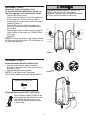
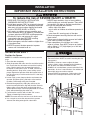
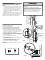
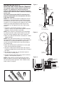
INSTRUCTION MANUAL
Model CG3800
Light Duty Commercial Door Operator
nal
o
i
t
Op ssory
e
Acc ilable ew
Avae 11 for the N
See
The Chamberlain Group
PO Box 6106
West Gosford NSW
www.chamberlainanz.com
Pag
N2966
TABLE OF CONTENTS
INTRODUCTION
2-5
Safety symbol review and signal word review . . . . . . . .2
Planning . . . . . . . . . . . . . . . . . . . . . . . . . . . . . . . . . . . . .3
Preparing your door . . . . . . . . . . . . . . . . . . . . . . . . . . . .4
Tools . . . . . . . . . . . . . . . . . . . . . . . . . . . . . . . . . . . . . . . .4
Specifications . . . . . . . . . . . . . . . . . . . . . . . . . . . . . . . . .4
Carton inventory . . . . . . . . . . . . . . . . . . . . . . . . . . . . . . .5
Hardware inventory . . . . . . . . . . . . . . . . . . . . . . . . . . . . .5
Test the safety reversal system . . . . . . . . . . . . . . . . . . .16
Test The Protector System® . . . . . . . . . . . . . . . . . . . . . .16
To open door manually . . . . . . . . . . . . . . . . . . . . . . . . .17
OPERATION
17-19
Operation safety instructions . . . . . . . . . . . . . . . . . . . . .17
Using your door operator . . . . . . . . . . . . . . . . . . . . . . .18
Care of your operator . . . . . . . . . . . . . . . . . . . . . . . . . .18
Using the remote control . . . . . . . . . . . . . . . . . . . . . . . .18
Diagnostics chart . . . . . . . . . . . . . . . . . . . . . . . . . . . . . .19
Replacing the battery . . . . . . . . . . . . . . . . . . . . . . . . . .20
ASSEMBLY
6
Attach the collar to the motor unit . . . . . . . . . . . . . . . . . .6
Attach mounting bracket to the motor unit . . . . . . . . . . .6
INSTALLATION
PROGRAMMING
20-21
To add or reprogram a hand-held remote control . . . . .20
To erase all codes from motor unit memory . . . . . . . . .20
To program wireless keypads . . . . . . . . . . . . . . . . . . . .21
7-14
Installation safety instructions . . . . . . . . . . . . . . . . . . . . .7
Position the operator . . . . . . . . . . . . . . . . . . . . . . . . . . . .7
Attach the emergency release rope and handle . . . . . . .8
Install the power door lock . . . . . . . . . . . . . . . . . . . . . . .8
Attach the cable tension monitor (Required) . . . . . . . . . .9
Electrical requirements . . . . . . . . . . . . . . . . . . . . . . . . .10
TROUBLESHOOTING . . . . . . . . . . . . . . . . . . . . . . . . .22
REPAIR PARTS
23
Installation parts . . . . . . . . . . . . . . . . . . . . . . . . . . . . . .23
Motor unit assembly parts . . . . . . . . . . . . . . . . . . . . . . .23
Install the wireless wall control . . . . . . . . . . . . . . . . . . .10
WARRANTY
Auxiliary inputs . . . . . . . . . . . . . . . . . . . . . . . . . . . . . . .11
Mount the EverCharge unit (SPU) (not provided) . . . . .11
Install The Protector System® . . . . . . . . . . . . . . . . . .12-13
ADJUSTMENT
24
14-17
Program the travel limits . . . . . . . . . . . . . . . . . . . . . . . .14
Setting the force . . . . . . . . . . . . . . . . . . . . . . . . . . . . . .15
Test cable tension monitor . . . . . . . . . . . . . . . . . . . . . .15
Test power door lock . . . . . . . . . . . . . . . . . . . . . . . . . . .15
INTRODUCTION
Safety Symbol Review
and Signal Word Review
This door operator has been designed and tested to offer safe service provided it is installed,
operated, maintained and tested in strict accordance with the instructions and warnings contained in
this manual.
When you see these Safety Symbols and Signal
Words on the following pages, they will alert you
to the possibility of serious injury or death if
you do not comply with the warnings that
accompany them. The hazard may come from
something mechanical or from electric shock.
Read the warnings carefully.
Mechanical
Electrical
When you see this Signal Word on the following
pages, it will alert you to the possibility of
damage to your door and/or the door operator if
you do not comply with the cautionary
statements that accompany it. Read them
carefully.
2
Planning
• The torsion bar must extend at least 25mm to 100mm
(1” to 4”) past the bearing plate.
• An electric outlet is required within 1.8m (6ʼ) of the
installation area. If outlet does not exist, contact a
qualified electrician.
• Depending upon buildingʼs construction, extension
brackets or wood blocks may be needed to install safety
reversing sensors.
• A model CM475 EverChargeTM Standby Power Unit
(SPU) is strongly recommended if there is no access
door to the building, as this operator cannot be used in
conjunction with an external emergency release
mechanism.
• Any gap between the floor and the bottom of the door
must not exceed 6mm (1/4”). Otherwise the safety
reversal system may not work properly.
NOTE: Inspect the torsion bar while the door is raised and
lowered. It is important that there is no noticeable
movement up and down or left and right. If this type of
movement is not corrected, life of this operator will be
greatly reduced.
Survey the area to see if any of the conditions below apply
to your installation. Additional materials may be required.
You may find it helpful to refer back to this page as you
proceed with the installation of your operator.
Depending on your requirements, there are several
installation steps which may call for materials or hardware
not included in the carton.
This operator is compatible with:
• Doors that use a torsion bar, springs and a door no
more than 3.8m (12.5ʼ) high.
• 100mm - 150mm drums (4” to 6”) , NOT TO BE USED
on tapered drums over 150mm (6”).
• High lift and standard lift sectional doors up to 3.8m
(12.5ʼ) high.
• Doors up to 5.5m (18ʼ) wide.
• Doors up to 16m2 (170 sq ft)
• 25mm (1”) torsion bar only.
• Review or inspect proposed installation area. Opener
can be installed on left or right side of door. Select the
side that meets the requirements listed below.
• Must have minimum of 64mm (2 1/2”) between the wall
and the center of the torsion bar.
• Must have minimum of 76mm (3”)between the ceiling
and the center of torsion bar.
• Must have minimum of 203mm (8”) between the side
wall (or obstruction) and the end of torsion bar.
Motor unit
Cable Tension
Monitor
Torsion Spring
Drum
Access Door
Powered
Door Lock
Safety
Reversing Sensor
Safety
Reversing
Sensor
Gap between floor
and bottom of door must not exceed 6 mm (1/4”)
3
Wireless wall control
Preparing your Door
Before you begin:
To prevent possible SERIOUS INJURY or DEATH:
• ALWAYS call a trained door systems technician if
door binds, sticks or is out of balance. An unbalanced
door may not reverse when required.
• NEVER try to loosen, move or adjust door, door
springs, cables, pulleys, brackets or their hardware,
ALL of which are under EXTREME tension.
• Disable ALL locks and remove ALL ropes connected
to the door BEFORE installing and operating the door
operator to avoid entanglement.
• This device is not intended for use by small children or
infirmed persons without supervision.
• young children should NOT be permitted to play with
the operator or remote controls.
• Disable locks.
• Remove any ropes connected to door.
• Complete the following test to make sure your door is
balanced and is not sticking or binding:
1. Lift the door about halfway as shown. Release the
door. If balanced, it should stay in place, supported
entirely by its springs.
2. Raise and lower the door to see if there is any
binding or sticking.
IF YOUR DOOR BINDS, STICKS OR IS OUT OF BALANCE, CALL A
TRAINED DOOR SYSTEMS TECHNICIAN.
3. Verify equal cable tension on each side of door.
Cable tension should remain equal during the entire
travel of the door.
4. The installer is to ensure that the temperature range
is suitable for the installation.
To prevent damage to door and operator:
• ALWAYS disable locks BEFORE installing and
operating the operator.
Specifications
Volts: 230-240 ~ V 50 Hz
Current: 145 Watts
Rated Load: 10Nm
Fmax: 40Nm
Max door height: 3.8m (12.5ʼ),
Max door width: 5.5m
Max: area 16m2
Temperature range: 500 C To 400 C
Sectional Door
Tools needed
During assembly, installation and adjustment of
the operator, instructions will call for hand tools
as illustrated below.
1
Drill
Pliers
2
Tape Measure
Wire Cutters
3/16" and 1/8"
Hex Key Wrench
5/32", 3/16", 5/16"
and 3/4" Drill Bits
Stepladder
Pencil
Screwdriver
1/4", 5/16" & 3/8" Sockets
and Wrench with 200mm Extension
Torque Meter (not shown)
Claw Hammer
Adjustable End Wrench
Needle Nose Pliers
Please note hardware accessories are supplied directly from Chamberlain USA,
therefore Tools and Drills are often stated in imperial measures.
4
Carton Inventory
Your door operator is packaged in one carton which contains the motor unit and the parts illustrated below. Note that
accessories will depend on the model purchased. If anything is missing, carefully check the packing material.
Hardware Inventory
PROTECTOR SYSTEM (IR) INSTALLATION
HARDWARE
Screw 10-32x3/8" (4)
Carriage Bolt 1/4"-20x1/2" (4)
Wing Nut 1/4"-20 (2)
Hex Nut 10-32x3/8" (4)
Hex Nut 1/4-20 (4)
Hex Head Screw 1/4-20x1-1/2" (2)
Hex Head Screw 14-10 x 1-1/2" (4)
Insulated Staple (20)
INSTALLATION HARDWARE
Hex Screw #14-10x1-7/8" (4)
Screw #6x-1" (2)
Hex Screw #6x1-1/4” (2)
Carriage Bolt 1/4"-20x1/2" (2)
Pan Head Screw 1/4"-20x1/2" (2)
Hex Head Screw #8x1" (2)
Self Tapping Screw #10-32 (2)
Wall Anchor (2)
Wall Anchor (Screw-In) (2)
Handle
Rope
Lock Template
5
ASSEMBLY STEP 1
Attach the Collar to the Motor Unit
To avoid installation difficulties, do not run
the door operator until instructed to do so.
• Loosen the collar screws.
• Attach collar to either the left or the right side
of the motor unit. Ensure that the collar is
seated all the way on motor shaft until stop is
reached (Figure 1).
• Position the collar so that the screws are
facing up (accessible when attached to the
torsion bar).
• Tighten both sides of collar screws equally to
secure collar to the motor unit (16Nm-19Nm .
of torque)
(Figure 2).
NOTE: For most installations the screws should
be facing up for easy access. Do not tighten set
screws until indicated.
To prevent possible SERIOUS INJURY or
DEATH, the collar MUST be properly
tightened. The door may not reverse correctly
or limits may be lost due to collar slip.
Collar Screw
Collar Screw
Set Screw
Set Screw
Collar Screw
Collar Screw
Left hand
Right hand
installation
installation
Figure 1
ASSEMBLY STEP 2
Attach Mounting Bracket to Motor Unit
• Loosely attach slotted side of mounting
bracket to the same side of the motor unit as
the collar, using
self-threading screws provided.
NOTE: Do not tighten until instructed.
Illustrations shown are for left side installation.
Figure 2
RIGHT
WRONG
HARDWARE SHOWN ACTUAL SIZE
Screw
#10-32
Alternate Mounting Kit (NOT SUPPLIED):
This kit allows model CG3800 to be
mounted below the torsion bar in the
case where the torsion bar is not
round or the normal mounting area
is obstructed.
Socket Wrench
CG480
6
INSTALLATION
IMPORTANT INSTALLATION INSTRUCTIONS
WARNING
To reduce the risk of SEVERE INJURY or DEATH:
1.READ AND FOLLOW ALL INSTALLATION
WARNINGS AND INSTRUCTIONS.
2.Install door operator ONLY on properly balanced
and lubricated the door. An improperly balanced
door may not reverse when required and could
result in SEVERE INJURY or DEATH.
3.ALL repairs to cables, spring assemblies and
other hardware MUST be made by a trained door
systems technician BEFORE installing operator.
4.Disable ALL locks and remove ALL ropes
connected to the door BEFORE installing
operator to avoid entanglement.
5 Mount emergency release handle no higher than
1.8m above floor.
6.NEVER connect the door operator to power
source until instructed to do so.
7.NEVER wear watches, rings or loose clothing
while installing or servicing operator. They could
be caught in the door or operator mechanisms.
8.Install wall-mounted door control:
• within sight of the door.
• out of reach of children at minimum operator of
1.5 m.
• away from ALL moving parts of the door.
9.Place entrapment warning label on wall next to
door control.
10.Place manual release/safety reverse test label in
plain view on inside of the door.
11.Upon completion of installation, test safety
reversal system. Door MUST reverse on contact
with a 40mm (1 1/2”) high object (or a 2x4 laid
flat) on the floor.
INSTALLATION STEP 1
Position the Opener
To prevent possible SERIOUS INJURY or DEATH:
• Concrete anchors MUST be used if mounting bracket
into masonry.
• NEVER try to loosen, move or adjust the door,
springs, cables, pulleys, brackets or their hardware,
ALL of which are under EXTREME tension.
• ALWAYS call a trained door systems technician if the
door binds, sticks or is out of balance. An unbalanced
door might not reverse when required.
• Operator MUST be mounted at a right angle to the
torsion bar to avoid premature wear on the collar.
NOTE: For additional mounting options see accessories
page.
1. Close the door completely.
2. Slide the operator with collar over the end of the torsion
bar. Ensure that the collar does not touch the bearing
plate. Check to make sure the mounting bracket is
located on a solid surface such as wood, concrete or
door/flag bracket. Snug collar screws to help assure
proper alignment of operator. Mark the bracket holes. It
may be necessary to cut the torsion bar if it is too long
or damaged.
3. Loosen collar screws from torsion bar and remove the
operator. Drill 5mm (3/16”) pilot holes at the marked
locations. Drill through steel plate if needed.
4. Reinstall the operator by sliding the collar over the
torsion bar until pilot holes align with bracket. Securely
tighten collar screws that attach to the torsion bar to
16Nm-19Nm of torque. Securely tighten both set screws
firmly, without damaging the motor unit.
5. Fasten bracket securely with 14-10x1-7/8" screws.
Tighten all mounting bracket hardware.
NOTE: The motor unit does not have to be flush to wall.
6. Use a staple to secure the antenna wire to prevent
antenna from being entangled in a door roller.
Torsion Bar
Staple
7
INSTALLATION STEP 2
Attach the Emergency Release Rope and
Handle
To prevent possible SERIOUS INJURY or DEATH from
a falling door:
• If possible, use emergency release handle to
disengage door ONLY when door is CLOSED. Weak
or broken springs or unbalanced door could result in
an open door falling rapidly and/or unexpectedly.
• NEVER use emergency release handle unless the
doorway is clear of persons and obstructions.
• Thread one end of the rope through the hole in the top
of the red handle so “NOTICE” reads right side up as
shown. Secure with an overhand knot at least 25mm
(1") from the end of the rope to prevent slipping.
• Thread the other end of the rope through the loop in the
emergency release cable.
• Adjust rope length so the handle is no higher than 1.8m
(6ʼ) above the floor. Secure with an overhand knot.
NOTE: If it is necessary to cut the rope, heat seal the cut
end with a match or lighter to prevent unraveling.
Motor Unit
Emergency
Release Cable
Overhand
Knot
Warning Label
Emergency
Release Handle
INSTALLATION STEP 3
Rope
Overhand
Knot
Install Power Door Lock
The lock is used to prevent the door from being
manually opened once the door is fully closed.
1. Select a door roller to mount the lock above. Check for
clearance. If possible select a roller on the same side of
the door as the motor unit. The second roller up from
the bottom is ideal in most installations.
2. Ensure the door track surface is clean and adhere lock
template with bottom edge just above the highest point
on the roller (Figure 1).
3. Drill holes as marked on the template.
4. Fasten power door lock to the outside of the door track
with hardware provided.
5. Run bell wire up wall to motor unit. Use insulated
staples to secure wire in several places.
6. Plug connector into the motor unit (Figure 2).
NOTE: Lock must be mounted within 3m (10') of the
power head.
TOP
DRILL 8mm
Approx. 7.6cm
132A2505
DRILL 19mm
DRILL 8mm
(3”)
Garage
Door Track
TOP
DRILL 5/16"
Figure 1
Staples
8
Figure 2
132A2505
DRILL 3/4"
HARDWARE SHOWN ACTUAL SIZE
Lock Screw
1/4-20 x 1/2" (2)
WARNING
NOTI
CE
Roller
DRILL 5/16"
Lock Template
INSTALLATION STEP 4
Figure 1
Attach the Cable Tension Monitor (Required)
This operator comes standard with the cable tension
monitor. It is supplied as a device to monitor the
cables for ANY slack that may occur and will reverse
the door when excessive slack is detected, eliminating
service calls.
The cable tension monitor MUST be connected and
properly installed before the door operator will move
in the down direction.
NOTE: The cable tension monitor is shipped for left side
installation. It is preferred that the cable tension monitor
be installed on the same side of the door as the operator.
If required, it can be mounted on the opposite side of door.
Remove the snap-ring holding the roller in place and
reassemble it on the opposite side of the cable tension
monitor.
1. Position the cable tension monitor as shown
(Figures 1 and 2). The cable tension monitor should be
located as close to the drum as possible.
NOTE: There must be no obstructions in the installation
area that prevent the cable tension monitor or the cable
itself from closing completely when slack is detected.
2. Make sure cable tension monitor is located over a wood
support member.
NOTE: If the cable tension monitor can not be mounted
into wood with the lag screws provided, it can be mounted
into 25mm (1”) or greater pasterboard using the wall
anchors (2) and the #8 hex head screws (2) provided in
the hardware bag.
3. Mark and drill 5mm (3/16”) pilot holes for screws (pilot
holes are not required for anchors).
4. Attach the cable tension monitor to the wall using the
hardware provided. Make sure that the roller is on top of
the cable.
5. Run bell wire to motor unit. Use insulated staples to
secure wire in several places.
6. Connect bell wire to the green quick-connect terminals
(polarity is not important) (Figure 3).
W
NOTE: Cable must have tension through entire travel.
Make sure there is no slack in cable on opposite side of
the door during normal operation. If this condition exists,
adjust cables as required.
Opener
Torsion Bar
Drum
D
Cable
2"-6"
(5 cm15 cm)
1/8"-1/4"
(3 mm-6 mm)
Cable
Tension
Monitor
Cable Tension
Monitor Roller
With Door Closed
Preferred Orientation
Figure 2
Wall
Drum
Cable
3/4" Min.
(18 mm Min.)
Figure 3
WHT/GRN
WHT/GRN
Cable Tension
Monitor
Strip wire (11mm)
To insert or release wire,
push in tab with
screwdriver tip
#8
He
ho
2)
r(
)
#6
(2
w
ew
re
Sc
r
Sc
nc
d
lA
ea
al
W
xH
Staples
(2
)
9
INSTALLATION STEP 6
Installing the Wireless Wall control (CG128)
To prevent possible SERIOUS INJURY or DEATH from
electrocution or fire:
• Be sure power is not connected to the operator, and
disconnect power to circuit BEFORE removing cover.
• Door installation and wiring MUST be in compliance
with ALL local electrical and building codes.
• NEVER use an extension cord, 2-wire adapter or
change plug in any way to make it fit outlet. Be sure
the operator is grounded.
• If the supply cord is damaged, it must be replaced by
the manufacturer or itʼs service agent or a similiarly
qualified person in order to avoid harzard.
Control must be mounted out of the reach of children
at a height of 1.5m with an unobstructed view of the
door.
• Ensure you CG3800 operator is switched off whilst
installing your wireless door control to prevent accidental
activation
• Remove the cover from the CG128.
• Mount CG128 as shown using the screws provided if
mounting into a wall box (not provided).
• If mounting directly on the wall use wall anchors
(provided) to fix unit to the plasterboard wall.
• Replace the cover plate and affix the warning label
adjacent the wall controller.
INSTALLATION STEP 5
Electrical Requirements
To avoid installation difficulties, do not run the
operator at this time.
To reduce the risk of electric shock, your door operator
has a grounding type plug with a third grounding pin. This
plug will only fit into a grounding type outlet. If the plug
doesn't fit into the outlet you have, contact a qualified
electrician to install the proper outlet.
+
RIGHT
Fix the emergency door release label adjacent to the
operator.
WRONG
+
GRIFCO
Mount the wireless wall control out of the
reach of children at 1.5m
To reduce risk of fire, explosion or chemical burn:
• Replace ONLY CR2032 batteries.
• Do NOT recharge, disassemble, heat above 75°C or
incinerate.
10
INSTALLATION STEP 7
Mounting the Evercharge Standby Power
Unit (SPU)
(not provided)
CM475 EverCharge
Standby Power Unit
If the optional CM475 Standby power supply unit is part of
this installation it should be installed at this time.
• The SPU can be mounted to either the ceiling or a wall
within 3' (.9 m) of the motor unit.
• Position the SPU as desired to a structural support
(ceiling joist or wall stud).
• Attach the SPU to the support using the mounting holes
on either side of the SPU.
• Secure the SPU using the 1-1/2" lag screws (2) provided
with the SPU unit.
• Connect the SPU cord into the connector on the bottom
of the motor unit.
• Follow all instructions included with the CM475 unit to
test for proper operation and testing of the SPU.
SPU Cord
Connector
AUXILIARY CONTACT INPUT STEP 8
(OPTIONAL)
Note: any connection to your CG3800 should
be voltage free and Normally open.
Strip wire (11 mm)
To connect to an auxillary activation device such as SPST
keyswitch, push button or relay contact to the terminals.
11 mm
To insert or release wire,
push in tab with
screwdriver tip
• Use a (figure 8) or bell cable to connect your com/no
contacts into the terminals as shown.
• Strip wires to about 11mm (7/16”)
• Use a screwdriver to press down the spring terminals
and insert cables.
Ensure cabling complies with building and electrical
standards.
or
Keyswitch
11
Standard SPST
push button com/no
INSTALLATION STEP 9
Install The Protector System®
Be sure power is not connected to the door operator
BEFORE installing the safety reversing sensor.
To prevent SERIOUS INJURY or DEATH from a closing
door:
• Correctly connect and align the safety reversing
sensor. This required safety device MUST NOT be
disabled.
• Install the safety reversing sensor between 50mm (2”)
and 150mm (6”) above the floor.
The safety reversing sensor must be connected and
aligned correctly before the door operator will move in
the down direction. This is a required safety device
and cannot be disabled.
INSTALLING THE BRACKETS
Be sure power to the operator is disconnected.
Figures 1, 2 and 3 show recommended assembly of
bracket(s) and "C" wrap based on the wall installation of
the sensors on each side of the door shown above, or on
the door tracks themselves. Figure 4 shows variations
which may fit your installation requirements better. Make
sure the wraps and brackets are aligned so the
sensors will face each other across the door.
• Connect each assembly to a slotted bracket, using the
hardware shown. Note alignment of brackets for left
and right sides of the door. Finger tighten the lock
nuts.
• Use bracket mounting holes as a template to locate and
drill (2) (4.8mm) diameter pilot holes on both sides of the
door, (100mm-150mm). Max height is (150mm).
• Attach bracket assemblies with 1/4"x1-1/2" lag screws as
shown.
• Adjust right and left side bracket assemblies to the same
distance out from mounting surface. Make sure all door
hardware obstructions are cleared. Tighten the nuts
securely.
Garage WALL Installation
1/4x1-1/2"
Lag Screws
Inside
Garage
Wall
#10-32
Lock Nuts
"C" Wrap
figure 2
Mounting Bracket
with Square Holes
Garage DOOR Track Installation
1/4"-20
Lock Nuts
Inside
Garage
Wall
Garage
Door Track
Mounting Bracket
with Square Holes
Drill 3/8"
(9,5mm) Holes
"C" Shaped
Wrap
1/4-20x1/2"
Carriage Bolts
Inside
Garage
Wall
Mounting
Bracket
with Slot
figure 3
Alternate Wall
Mount
Mounting
Bracket with
Square Holes
"C" Wrap
Sensor
Indicator Light
Garage
Floor
Inside
Garage
Wall
Indicator Light
figure 4
Alternate Floor
Mount
Sensor
Mounting Bracket
with Square Holes
Mounting Bracket
with Slot
Attach with
concrete anchors
(not provided)
"C"
Wrap
Garage
Floor
ALL Installations
Mounting Bracket
With Square Holes
Mounting Bracket
with Slot
1/4"-20
Lock Nuts
• Centre each sensor unit in a "C" wrap with lenses
pointing toward each other across the door.
• Secure sensors with the hardware shown in Figure 6.
Finger tighten the wing nut on the receiving eye to allow
for final adjustment. Securely tighten the sending eye wing
nut.
• Run wires from both sensors to the operator as shown in
Figure 5. Use insulated staples to secure the wire to the
wall and ceiling.
• Connect both sets of wires to the operator terminals as
shown page 13.
• Plug in the operator. If your operator has the MultiFunction Door Control, make sure the Lock Feature is off.
Red indicator lights in both the sending and receiving eyes
will glow if wiring connections and alignment are correct.
If the indicator lights are blinking (and the invisible light
beam path is not obstructed), alignment is required.
• Loosen the receiving eye wing nut to allow slight rotation
of unit. Adjust sensor vertically and/or horizontally until the
red indicator light glows.
• When indicator lights are glowing in both units, tighten the
wing nut in the receiving eye unit.
figure 1
1/4-20x1/2" Carriage Bolts
(with square shoulder)
figure 5
Wing Nut
"C" Wrap
"C" Wrap
#10-32x3/8"
Screws
Wire
Indicator
Light
12
Sensor
1/4-20x1-1/2"
Hex Bolt
figure 6
TROUBLESHOOTING THE SAFETY
REVERSING SENSORS
MOUNTING AND WIRING THE SAFETY
REVERSING SENSORS
1. If the sending eye indicator LEDs are both blinking
• Run the wires from both safety reversing sensors to the
after installation, check for:
operator. Use insulated staples to secure wire to wall
and
ceiling.
• Electric power to the operator.
• Strip 11mm (7/16") of insulation from each set of wires.
• A short in the white or white/black wires. These can
Separate white and white/black wires sufficiently to
occur at staples, or at operator connections.
connect to the operator quick-connect terminals: white to
• Incorrect wiring between safety reversing sensors and
white and white/black to grey (Figure 6).
operator.
• A broken wire.
2. If the sending eye indicator light glows steadily but the
receiving eye indicator light doesn't:
• Check alignment.
• Check for an open wire to the receiving eye.
3. If the receiving eye indicator light is dim, realign
either sensor.
NOTE: When the invisible beam path is obstructed or
misaligned while the door is closing, the door will reverse.
If the door is already open, it will not close.
and 10 clicks will sound.) See page 19.
Bell Wire
Motor unit
Bell Wire
To CableTension Monitor
To Power
Door Lock
Connect Wire to
Quick-Connect
Terminals
Power Door Lock
Sensor
Connections
com
no
WHT/BLK
WHT
To Door Control
dry contact
Quick-Connect Terminals
MAX height
150mm (6”)
MIN height
50mm (2”)
Safety Reversing Sensor
Sensor
Invisible Light Beam
Safety
Reversing
Sensor
Protection Area
Sensor
13
ADJUSTMENT STEP 1
Program the Travel Limits
Travel limits regulate the points at which the door will
stop when moving up or down. Follow the steps below
to set the limits.
Figure 1
Indicator
Light
Without a properly installed safety reversal system,
persons (particularly children) could be SERIOUSLY
INJURED or KILLED by a closing door.
• NEVER learn forces or limits when door is binding or
sticking. Repair door first.
• Incorrect adjustment of the door travel limits will
interfere with proper operation of safety reversal
system.
• After ANY adjustments are made, the safety reversal
system MUST be tested. Door MUST reverse on
contact with 40mm high (1 1/2”) object (or 4x2 laid
flat) on floor.
Black
Button
Purple
Button
To program the travel limits:
Adjust the position of the door by using the black and
purple buttons. Black moves the door UP (open) and
purple moves the door DOWN (close).
1. Setting the UP position: Press and hold the black
button until the yellow indicator light starts flashing
slowly then release.
2. Push and hold the black button until the door reaches
the desired UP (open) position (Figure 2).
NOTE: Check to be sure the door opens high enough for
your vehicle.
3. Push the remote control or door control (Figure 3). This
sets the UP (open) limit and begins closing the door.
NOTE: Excessive movement of the motor unit will cause
premature wear. See Troubleshooting section.
4. Immediately when the door begins to move down, press
and release either the black or purple button. This will
stop the door.
5. Setting the DOWN position: Push and hold the purple
button until the door reaches the desired DOWN
(closed) position (Figure 4).
6. Once the door is closed, check for proper pressure on
the door (you should be able to manually push the door
down a 1/16 of an inch). If there appears to be too
much pressure on the door, you may toggle the door
back and forth using the black and purple buttons to
reach the desired position.
7. Push the remote control or the door control (Figure 3).
This sets the DOWN (close) limit and should bring the
door to the open position.
• If the operator is not stopping exactly where you would
like it, repeat steps 1 through 7 and program the limits
again.
• When the unit stops in both the desired up (open) and
down (close) positions, proceed to Adjustment Step 2,
Setting the Force.
To prevent damage to vehicles, be sure fully open door
provides adequate clearance.
Figure 2
BLACK
Push and hold
until the door
is at desired UP
position
PURPLE
F
Figure
3
o
or
O
GRIFC
Figure 4
BLACK
Push either
button to stop
door at desired
DOWN position
PURPLE
14
ADJUSTMENT STEP 2
Setting the Force
The force setting button is located on the front panel.
The force setting measures the amount of force
required to open and close the door.
1. Locate the purple button on the unit (Figure 1).
2. Push the purple button twice to enter unit into Force
Adjustment Mode (Figure 2). The LED (Indicator Light)
will flash quickly.
3. Push the remote control or door control (Figure 3). The
door will travel to the DOWN (close) position. Push the
remote control or door control again, the door will travel
to the UP (open) position. Push the remote control or
door control a third time to send the door to the DOWN
(close) position.
The LED (Indicator Light) will stop flashing when the force
has been learned.
The unit has learned the forces required to open and close
your door.
The door must travel through a complete cycle, UP and
DOWN, in order for the force to be set properly. If the unit
cannot open and close your door fully, inspect your door to
insure that it is balanced properly and is not sticking or
binding. See page 4, “Preparing your door.”
ADJUSTMENT STEP 3
Test Cable Tension Monitor
If your cable tension monitor has been activated the unit
will click 9 times. See (Figure 1) page 19.
ADJUSTMENT STEP 4
Test Power Door Lock
TEST
• With the door fully closed, the power door lock bolt
should be protruding through the track.
• Operate the door in the open direction. The power door
lock should retract before the door begins to move.
• Operate the door in the down direction. When the door
reaches the fully closed position, the power door lock
should automatically activate to secure the door.
NOTE: If the power door lock does not function, the lock
can be manually released by sliding the manual release
handle to the open position.
Without a properly installed safety reversal system,
persons (particularly children) could be SERIOUSLY
INJURED or KILLED by a closing the door.
• NEVER learn forces or limits when door is binding or
sticking. Repair door first
• Too much force on door will interfere with proper
operation of safety reversal system.
• After ANY adjustments are made, the safety reversal
system MUST be tested. Door MUST reverse on
contact with 40mm (1 1/2”) high object (or 4x2 laid
flat) on floor.
Figure 1
Indicator
Light
Figure 2
Black
Button
Push Purple button
twice to enter
unit into Force
Adjustment Mode
BLACK
PURPLE
Purple
Button
Figure 3
O
GRIFC
or
15
ADJUSTMENT STEP 5
Test the Safety Reversal System
Without a properly installed safety reversal system,
persons (particularly children) could be SERIOUSLY
INJURED or KILLED by a closing the door.
• Safety reversal system MUST be tested every month.
• If one control (force or travel limits) is adjusted, the
other control may also need adjustment.
• After ANY adjustments are made, the safety reversal
system MUST be tested. Door MUST reverse on
contact with 40mm (1 1/2”) high object (or 4x2 laid
flat) on the floor.
TEST
• With the door fully open, place a 40mm (1 1/2”) board
(or a 4x2 laid flat) on the floor, centered under the the
door.
• Operate the door in the down direction. The door must
reverse on striking the obstruction. Upon successful
safety reversal test proceed to Adjustment Step 4.
ADJUST
• If the door stops on the obstruction, it is not traveling far
enough in the down direction. Complete Adjustment
Steps 1 and 2 Programming the Limits and Forces.
• Repeat the test.
• When the door reverses on the 40mm (1 1/2”) board (or
4x2 laid flat), remove the obstruction and run the
operator through 3 or 4 complete travel cycles to test
adjustment.
• If the unit continues to fail the Safety Reverse Test, call
for a trained door systems technician.
IMPORTANT SAFETY CHECK:
Test the Safety Reverse System after:
• Each adjustment of limits, or force controls.
• Any repair to or adjustment of the door (including
springs and hardware).
• Any repair to or buckling of the floor.
• Any repair to or adjustment of the operator.
ADJUSTMENT STEP 6
Test The Protector System®
40mm (1 1/2”) plank
(or a 4x2 laid flat)
• Press the remote control push button to open the door.
• Place the operator carton in the path of the door.
• Press the remote control push button to close the door.
The door will not move and the unit will make a clicking
noise
The door operator will not close from a remote if the
indicator light in either sensor is flashing or off (alerting
you to the fact that the sensor is misaligned or
obstructed).
If the operator closes the door when the safety
reversing sensor is obstructed, do not operate the
door. Call for a trained door systems technician.
Without a properly installed safety reversing sensor,
persons (particularly children) could be SERIOUSLY
INJURED or KILLED by a closing door.
16
Safety Reversing Sensor
Safety Reversing Sensor
OPERATION
IMPORTANT SAFETY INSTRUCTIONS
WARNING
To reduce the risk of SEVERE INJURY or DEATH:
1. READ AND FOLLOW ALL WARNINGS AND
INSTRUCTIONS.
2. ALWAYS keep remote controls out of reach of
children. NEVER permit children to operate or play
with the wireless door control or remote controls.
3. The appliance is not intended for use by young
children or infirm persons without supervision.
4. ONLY activate the door when it can be seen clearly, it
is properly adjusted and there are no obstructions to
door travel.
5 ALWAYS keep the door in sight until completely
closed. NO ONE SHOULD CROSS THE PATH OF
THE MOVING DOOR.
6. NO ONE SHOULD GO UNDER A STOPPED,
PARTIALLY OPENED DOOR.
7. If possible, use emergency release handle to
disengage door ONLY when the door is CLOSED.
Weak or broken springs or unbalanced door could
result in an open door falling rapidly and/or
unexpectedly.
8. NEVER use emergency release handle unless the
doorway is clear of persons and obstructions.
9. After ANY adjustments are made, the safety reversal
system MUST be tested.
10.Safety reversal system MUST be tested every month.
the door MUST reverse on contact with 40mm
(1 1/2”) high object (or a 4x2 laid flat) on the floor.
11. ALWAYS KEEP THE DOOR PROPERLY
BALANCED (see page 3). An improperly balanced
door may not reverse when required and could
result in SEVERE INJURY or DEATH.
12. ALL repairs to cables, spring assemblies and other
hardware, ALL of which are under EXTREME
tension, MUST be made by a trained door systems
technician.
13. ALWAYS disconnect electric power to the door
operator BEFORE making ANY repairs or removing
covers.
14. Permanently fix the Emergency release instruction
Label adjacent to the release handle.
15. SAVE
THESE INSTRUCTIONS.
EMERGENCY DOOR RELEASE
To prevent possible SERIOUS INJURY or DEATH from a falling door:
• If possible, use emergency release handle to disengage door ONLY when door is CLOSED. Weak or broken springs
or unbalanced door could result in an open door falling rapidly and/or unexpectedly.
• NEVER use emergency release handle unless the doorway is clear of persons and obstructions.
ADJUSTMENT STEP 7
To Open the Door Manually
Power Door Lock
Disengage door lock before proceeding. The door should be fully
closed if possible. Pull down on the emergency release handle until
a click noise is heard from the unit and lift the door manually. To
reconnect the door to the operator, pull down the emergency
release handle straight down a second time until a click noise is
heard from the unit. The door will reconnect on the next UP or
DOWN operation.
Test the emergency release:
• Make sure the door is closed.
• Pull the emergency release handle. The door should then be able
to be opened manually.
• Return the door to the closed position.
• Pull the emergency handle a second time.
• Reconnect the door to the operator.
17
Manual Releas
Lock Bolt
“Locked”
WARNING
Emergency
Release Handle
NOT
ICE
Using Your The Door Opener
Your Security:® operator and hand-held remote control
have been factory-set to a matching code which changes
with each use, randomly accessing over 100 billion new
codes. Your operator will operate with up to eight Security:®
remote controls and one Security:® Keyless Entry System.
If you purchase a new remote, or if you wish to deactivate
any remote, follow the instructions in the Programming
section.
Using your CG844 4ch Mini Remote Control
Activate your operator with any of the following:
• The hand-held Remote Control: Hold top middle button
down until the door starts to move.
• The wireless wall control CG128 press and hold the
large round button down until the door starts to move.
• The Keyless Entry (See Accessories): If provided with
your door operator, it must be programmed before use.
See Programming.
GRIFCO
When the operator is activated (with the safety
reversing sensor correctly installed and aligned)
1. If open, the door will close. If closed, it will open.
2. If closing, the door will reverse.
3. If opening, the door will stop.
4. If the door has been stopped in a partially open position,
it will close.
5. If obstructed while closing, the door will reverse. If the
obstruction interrupts the sensor beam, the operator wil
click for five seconds.
6. If obstructed while opening, the door will stop.
7. If fully open, the door will not close when the beam is
broken. The sensor has no effect in the opening cycle.
If the sensor is not installed, or is misaligned, the door
wonʼt close from a hand-held remote. However, you can
close the door with the Door Control, the Outside Keylock,
or Keyless Entry, if you activate them until down travel is
complete. If you release them too soon, the door will
reverse.
Using your CG128 Wireless Wall Control
GRIFCO
CARE OF YOUR OPENER
MAINTENANCE SCHEDULE
Once a Month
• Manually operate door. If it is unbalanced or binding, call
a trained door systems technician.
• Check to be sure door opens & closes fully. Adjust limits
and/or force if necessary (see Adjustment Steps
1 and 2).
• Repeat the safety reverse test. Make any necessary
adjustments (see Adjustment Step 5).
Once a Year
• Oil door rollers, bearings and hinges. The operator does
not require additional lubrication. Do not grease the door
tracks.
18
Unit
“Learn”
Button LED
or Diagnostic
LED
“Learn”
Button
Diagnostic Chart
1 FLASH
Safety reversing sensors
wire open (broken or
disconnected).
OR
2 FLASHES
Safety reversing sensors
wire shorted or black/white
wire reversed.
3 FLASHES
Door control or
wire shorted.
4 FLASHES
Safety reversing sensors
slightly misaligned
(dim or flashing LED).
5 FLASHES
Possible RPM sensor
failure. Unplug to reset.
9 FLASHES
Cable tension monitor
reversal.
Installed
Safety Reversing
Sensor
Your door operator is programmed with self-diagnostic
capabilities. The “Learn” button/diagnostic LED will flash a
number of times then pause signifying it has found a
potential issue. Consult Diagnostic Chart below.
Symptom: One or both of the Indicator lights on the safety reversing sensors
do not glow steady.
• Inspect sensor wires for a short (staple in wire), correct wiring polarity (black/white
wires reversed), broken or disconnected wires, replace/attach as needed.
• Disconnect all wires from back of motor unit.
• Remove sensors from brackets and shorten sensor wires to 30-60mm (1-2”) from
back each of sensor.
• Reattach sending eye to motor unit using shortened wires. If sending eye indicator
light glows steadily, attach the receiving eye.
• Align sensors, if the indicator lights glow replace the wires for the sensors. If the
sensor indicator lights do not light, replace the safety reversing sensors.
Symptom: LED is not lit on door control.
• Inspect door Control/wires for a short (staple in wire), replace as needed.
• Disconnect wires at door control, touch wires together. If motor unit activates,
replace door control.
• If motor unit does not activate, disconnect door control wires from motor unit.
Momentarily short across red and white terminals with jumper wire. If motor unit
activates, replace door control wires.
Symptom: Sending indicator light glows steadily, receiving indicator light is
dim or flashing.
• Realign receiving eye sensor, clean lens and secure brackets.
• Verify door track is firmly secured to wall and does not move.
Symptom: The RPM Sensor = Short travel 150-200mm (6-8").
• Unplug unit to reset. Try to operate motor unit, check diagnostic code.
• If it is still flashing 5 times and motor unit moves 150-200mm (6-8"),The unitʼs APE
(Absolute Positioning Encoder) may need to be replaced, for details contact your
Chamberlain reseller.
Symptom: Door reverses while closing.
• Check for possible door obstructions and remove.
• Check that the cable tension monitor is properly connected to the operator.
• Replace the cable tension monitor.
19
PROGRAMMING
Your door operator has already been programmed at the factory to operate with your hand-held remote control. The door will
open and close when you press the large push button.
Below are instructions for programming your operator to operate with additional Security:® remote controls.
To Add or Reprogram a Hand-held Remote Control
USING THE “LEARN” BUTTON
To Erase All Codes From
Motor Unit Memory
To deactivate any unwanted remote,
first erase all codes:
Press and hold the “learn” button on
motor unit until the learn indicator
LED goes out (approximately 69 seconds). All previous codes are
now erased. Reprogram each remote
or keyless entry you wish to use.
GRIFCO
The Remote Control Battery
1. Press and release the purple “learn”
button on the motor unit. The learn
indicator LED will glow steadily for 30
seconds.
2. Within 30 seconds, press and hold the
button on the hand-held remote* that
you wish to operate your door.
3. Release the button when the motor
unit LED two clicks.
To prevent possible SERIOUS INJURY or DEATH:
• NEVER allow small children near batteries.
• If battery is swallowed, immediately notify doctor.
Replacing the Battery
O
GRIFC
k
clic k
clic
battery
4-Button Remote
If you have multiple door the CG844 you to open up to four
doors seperatly using secure and reliable 433MHz rolling
code.
Simply assign one button per door and program your
remote into all four doors as outline above.
spacer
$
battery case
coin
To replace battery, use a coin to turn the battery
cover plate. Remove the Battery from the spacer
and place a new battery into the spacer (observing
polarity) then reseal the case using the coin to twist
the backing plate back into place.
To reduce risk of fire, explosion or chemical burn:
• Replace ONLY CR2025 batteries.
• Do NOT recharge, disassemble, heat above 75°C or
incinerate.
20
(OPTIONAL)
To Add, Reprogram or Change a Keyless Entry PIN
USING THE “LEARN” BUTTON
To change an existing, known PIN
If the existing PIN is known, it may be changed by one
person without using a ladder.
1. Press the four buttons for the present PIN, then press and
hold the # button.
The operator will click twice. Release the # button.
2. Press the new 4-digit PIN you have chosen, then
press Enter.
The motor unit will click once when the PIN has been
learned.
Test by pressing the new PIN, then press Enter. The door
should move.
To set a temporary PIN
You may authorize access by visitors or service people with a
temporary 4-digit PIN. After a programmed number of hours
or number of accesses, this temporary PIN expires and will
no longer open the door. It can be used to close the door
even after it has expired. To set a temporary PIN:
1. Press the four buttons for your personal entry PIN (not the
last temporary PIN), then press and hold the ] button.
The operator will click. Release the button.
1. Press and release the purple “learn”
button on motor unit. The learn
indicator LED will glow steadily for 30
seconds.
2. Within 30 seconds, enter a four digit
personal identification number (PIN)
of your choice on the keypad. Then
press and hold the ENTER button.
3. Release the button when the motor
unit LED truns off and two clicks are
heard.
2. Press the temporary 4-digit PIN you have chosen, then
press Enter.
The operator will click four times.
3. To set the number of hours this temporary PIN will work,
press the number of hours (up to 255), then press ].
OR
3. To set the number of times this temporary PIN will open
door, press the number of times (up to 255), then press #.
The operator will click once when the temporary PIN has
been learned.
Test by pressing the four buttons for the temporary PIN, then
press Enter. The door should move. If the temporary PIN was
set to a certain number of openings, remember that the test
has used up one opening.To clear the temporary password,
repeat steps 1-3, setting the number of hours or times to 0 in
step 3.
One Button Close: Opener can be closed by pressing only
the ENTER button if the one button close feature has been
activated. This feature has been activated at the factory. To
activate or deactivate this feature press and hold buttons 1
and 9 for 10 seconds. The keypad will blink twice when the
one button close is active. The keypad will blink four times
when one button close is deactivated.
k
clic k
i
cl c
21
8. The door reverses for no apparent reason and operator
LED doesnʼt blink:
TROUBLESHOOTING
1. The operator doesn't operate from either the Door
Control or the remote control:
• Does the operator have electric power? Plug a lamp into the
outlet. If it doesn't light, check the fuse box or the circuit
breaker. (Some outlets are controlled by a wall switch.)
• Have you disabled all door locks? Review installation
instruction warnings on page 7.
• Is there a build-up of ice or snow under the door? The door
may be frozen to the ground. Remove any restriction.
• The door spring may be broken. Have it replaced (see page
3 for reference).
•
•
•
•
•
3. The door operates from the Door Control, but not from
the remote control:
• Is the door push bar flashing? If so, Lock mode is engaged.
Make sure it is off by pressing the
Lock button for two seconds.
•
•
•
•
• Change the location of the remote control in your car.
• Check to be sure the antenna on the side or back panel of
motor unit extends fully downward.
•
• Some installations may have shorter range due to a metal
door, foil backed insulation, or metal
siding.
•
Be sure that all remote control push buttons are off.
Remove the bell wire from the door control terminals and
operate from the remote only. If this solves the problem, the
door control is faulty (replace), or there is an intermittent
short on the wire between the control console and the motor
unit.
Clear memory and re-program all remote controls.
6. The door doesn't open completely:
Check power door lock.
Is something obstructing the door? Is it out of balance, or
are the springs broken? Remove the obstruction or repair
the door.
•
Manually open the power door lock.
Use the emergency release handle to disconnect the door.
The door can be opened and closed manually. When power
is restored, pull manual release a second time.
If an EverCharge Unit is connected, the operator should be
able to operate up to 20 times without power.
Collar not tightened securely. Tighten collar
(see Assembly Steps 1 and 2) and reprogram limits
(see Adjustment Step 1).
14. The operator moves when the door is in operation:
•
Some minor movement is normal for this product. If it is
excessive the collar will wear prematurely.
•
Check to make sure the torsion bar is not moving left/right
excessively.
•
Check that the operator is mounted at a right angle to the
jackshaft. If not, move the position of the mounting bracket.
•
•
Check cable tension monitor (see installation step 4).
If the operator clicks, check the safety reversing sensor. See
Installation Step 9.
If the operator does not click and it is a new installation. See
Adjustment Step 2. For an existing installation, see below.
Repeat the safety reverse test after the adjustment is complete.
If the problem occurs on the first operation of the operator,
door may be locked. Disable the power door lock.
Check to make sure the torsion bar is not visibly moving up
and down as it rotates.
15. Power lock makes noise when operating.
7. The door opens but won't close:
•
The door springs may be broken. See above.
13. Door loses limits.
5. The door opens and closes by itself:
•
The door may be out of balance or the springs may be
broken. Close the door and use the emergency release
handle to disconnect the door. Open and close the door
manually. A properly balanced door will stay in any point of
travel while being supported entirely by its springs. If it does
not, disconnect the operator and call a trained door systems
technician.
12.The operator won't operate due to power failure:
4. The remote control has short range:
•
Check the safety reversing sensor. Remove any obstruction
or align the receiving eye. See Installation Step 9.
11.The operator motor hums briefly, then won't work:
• Program the operator to match the remote control code.
(Refer to instructions on the motor unit panel.) Repeat with all
Remote.
•
Review Adjustment Step 2.
10. The operator strains to operate door:
•
• If the LED turns on and is strong check to ensure the unit is
programmed into the unit (see page 20).
•
Clear any ice or snow from the floor area where the door
closes.
9. The door reverses for no apparent reason and operator
LED blinks for 5 seconds after reversing:
• Check the LED on the Wall Control to ensure the LED turns
on when button is pushed. If the LED is weak or not on
Change the batteries. (Remove cover and replace with
CR2032 batteries X 2)
•
Is something obstructing the door? Pull the emergency
release handle. Operate the door manually. If it is
unbalanced or binding, call a trained door systems
technician.
Repeat safety reverse test after adjustments.
2. Opener operates from the remote, but not from the
Wireless Wall Control:
•
Check cable tension monitor (see installation step 4).
22
Call Chamberlain Grifco® dealer for replacement power lock.
REPAIR PARTS
Installation Parts
1
6
5
2
7
NOT
ICE
8
4
3
KEY
NO.
1
2
3
4
5
PART
NO.
41A6102-1
CG128
C77
41A6388
CG844
6
DESCRIPTION™
7
8
Electric lock
Wireless wall control
Protector system
Collar with set screws
4ch rolling code remote
Motor Unit Assembly Parts
41A4582
41A6104-1
41C0902
Emergency release rope & handle
assembly
Cable tension monitor
Mounting bracket
41A6348-4
41A
632
41A6408
D
41
J0
Z
AN
1
0
41C169-1
23
41A6095
0-1
WARRANTY / GUARANTEE
Chamberlain Australia Pty Ltd herein referred to as “The Company”
(a) The Company shall guarantee the goods for a period of two years from the date of invoice
against any defects in construction or operation arising solely from faulty design, materials or
workmanship subject to the following clauses.
(b)The Company shall at its option, repair, modify or replace defective parts or units at its own
expense and within a reasonable time but the Company shall not unless otherwise agreed in
writing be liable for costs associated with removal, replacement, transport or travelling expenses
incurred by the Purchaser in obtaining the goods and returning them to the Company.
(c) The Company does not guarantee the goods where:-
(I) the defect rises from materials supplied by the Purchaser or a design requested by the
purchaser; or
(ii) the defect arises from ordinary wear and tear, neglect or misuse by the Purchaser, accident,
lack of care, insufficient maintenance, incorrect installation or improper use of the goods; or
(iii) the defect arises from force majeure; or
(iv) the Purchaser has in any way modified or repaired the goods without the Company's prior
written consent; or
(v) the Purchaser has not complied with any written or oral instructions concerning the operation
and maintenance of the goods; or
(vi) the Purchaser is in default in the observance or performance of any other provisions of the
contract; or
(vii) The Grifco electric motors are used in conjunction with controls other than those assembled
and supplied by the Company.
(d) Where warranty is approved for goods in a used condition, such goods will be repaired or
replaced and returned to the purchaser as the Company sees fit. Refunds or credits will only be
considered for goods not used and in new, undamaged condition.
(e) The Company's liability under this guarantee will be strictly limited to repairing or replacing a
defective product at the Companyʼs premises, as it may elect.
(f) The provision of sub-clauses (a) and (b) are stipulated for the benefit of the Purchaser only
and are not intended for the benefit of any third party.
(g) Save for sub-clauses (a) and (b) the Company does not give any warranty or guarantee or
make representations whatever in respect of the goods or the fitness of the goods or any part
thereof or any particular purposes (whether or not that purpose is known to the Company).
Chamberlain Australia Pty Ltd
15 Dell Rd West Gosford
NSW 2250
Australia
Ph. +61 (02) 43233877
Fax. +61 (02) 43233882
Toll free: 1800 GRIFCO
www.grifco.com.au
114A3506B
© 2008, The Chamberlain Group, Inc.
All Rights Reserved