1
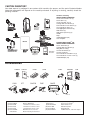
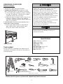
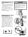
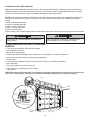
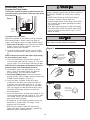
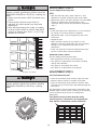
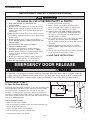
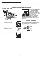
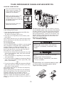
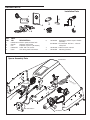
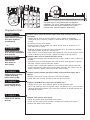
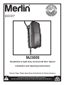
gomerlin.com.au
gomerlin.co.nz
MJ3800
Residential & Light Duty Commercial Door Opener
Installation and Operating Instructions
Owners Copy: Please keep these instructions for future reference
This manual contains IMPORTANT SAFETY information
DO NOT PROCEED WITH THE INSTALLATION BEFORE READING THOROUGHLY
START BY READING THESE IMPORTANT SAFETY INSTRUCTIONS
WARNING
• Failure to comply with the following instructions may result in serious personal injury or property damage.
• Read and follow all instructions carefully.
• The garage door opener is designed and tested to offer safe service provided it is installed and
operated in strict accordance with the instructions in this manual.
These safety alert symbols mean WARNING : A possible risk to personal safety or
property damage exists.
Keep garage door balanced. Do not let the garage door
opener compensate for a binding or sticking garage door.
Sticking, binding or unbalanced doors must be repaired
before installing this opener.
The Protector SystemTM must be used for all installations
where the closing force as measured on the bottom of the
door is over 400 N (40 kgf). Excessive force will interfere with
the proper operation of the Safety Reverse System or damage
the garage door.
SPECIAL NOTE: Merlin strongly recommends that The
Protector SystemTM be installed on all garage door openers.
Do not wear rings, watches or loose clothing while
installing or servicing a garage door opener. Wear gloves,
safety goggles and suitable protective clothing where
appropriate.
After installation, ensure that the parts of the door do not
extend over public footpaths or roads.
Install the wireless wall control (or any additional wall control) in
a location where the garage door is visible, at a height of at
least 1.5 m and out of the reach of children. Do not allow
children to operate push button(s) or transmitter(s). Serious
personal injury from a closing garage door may result from
misuse of the opener.
Frequently examine the door installation, in particular
cable, springs and mountings for signs of wear, damage or
imbalance. Do not use if repair or adjustment is needed
since springs and hardware are under extreme tension
and a fault can cause serious personal injury.
To avoid serious personal injury from entanglement,
remove all ropes, chains and locks connected to the
garage door before installing the door opener.
Permanently fasten the Warning Labels in Prominent Places,
adjacent to Wall Controls and on manual release mechanism as
a reminder of safe operating procedures.
Installation and wiring must be in compliance with your
local building and electrical codes.
The safety reverse system test is very important. Your
garage door MUST reverse on contact with a 40 mm
obstacle placed on the floor. Failure to properly adjust the
opener may result in serious personal injury from a closing
garage door. Repeat the test once a month and make
any necessary adjustments.
Activate opener only when the door is in full view, free of
obstructions and the opener is properly adjusted. No one
should enter or leave the garage while the door is in motion.
Automatic Door- The door may operate unexpectedly, therefore
do not allow anything to stay in the path of the door.
Do not allow children to play near the door, or with door
controls. Keep remotes away from children.
This appliance is not intended for use by persons
(including children) with reduced physical, sensory or
mental capabilities, or lack of experience and knowledge,
unless they have been given supervision or instruction
concerning use of the appliance by a person responsible
for their safety.
Disconnect electric power to the garage door opener before
making repairs or removing covers.
If the supply cord is damaged, it must be replaced by the
manufacturer, its service agent or similarly qualified persons in
order to avoid hazard.
Use the Manual Release only for the seperation of the
carriage from the drive and - if possible - ONLY with the
door closed. Do not use the red handle to push the door
up or pull it down. Operation of the emergency release can
lead to uncontrolled movements of the door, if springs are
weak or broken or if the door is unbalanced. Mount the
release handle of the emergency release at a height less
than 1.8 m from the floor.
This opener should not be installed in a damp or wet space
exposed to weather.
To avoid damage to very light doors (such as fibreglass,
aluminium or steel doors), an appropriate reinforcement should
be added. To do so, contact the door manufacturer.
SAVE THESE INSTRUCTIONS
NOTE: If your garage has no service entrance door, a CM1702 outside quick release must be installed.
This accessory allows manual operation of the garage door from outside in case of power failure.
CONTENTS
PAGE
SAFETY INSTRUCTIONS . . . . .2
CARTON INVENTORY . . . . . . .3
ACCESSORIES . . . . . . . . . . . 3
SPECIFICATION . . . . . . . . . . .4
TOOLS REQUIRED . . . . . . . . .4
PREPARE & TEST THE DOOR . .4
DOOR REQUIREMENTS . . . . . .5
ASSEMBLY . . . . . . . . . . . . . . .6
INSTALLATION . . . . . . . . .7-10
CONNECT ELECTRIC POWER .10
INSTALL MULTI-FUNCTION DOOR
2
CONTROL . . . . . . . . . . . . . .10
INSTALL THE PROTECTOR
SYSTEM . . . . . . . . . . . . . . .11
AUTO CLOSE . . . . . . . . . . . .13
ADJUSTMENT . . . . . . . . .14-17
WIRELESS PROGRAMMING 18-19
REPAIR PARTS . . . . . . . . . . .20
DIAGNOSTIC CHART . . . . . . .21
TROUBLESHOOTING . . . . . . .22
CARE OF YOUR OPENER . . . . 23
OPERATION OF YOUR OPENER23
WARRANTY . . . . . . . . . . . . .24
CARTON INVENTORY
Your door opener is packaged in one carton which contains the opener and the parts illustrated below.
Note that accessories will depend on the model purchased. If anything is missing, carefully check the
packing material.
2 x C945 3ch
rolling code
transmitters
CM128 Wireless
Wall Button
Opener
Manual
TM
LOCK
CM475 Battery
Backup Unit
Multi function
door control
LIGHT
Hardware Inventory
INSTALLATION HARDWARE
Hex Screw #14-10x1-7/8" (4)
Screw #6x-1" (2)
Hex Screw #6x1-1/4” (2)
Carriage Bolt 1/4"-20x1/2" (2)
Pan Head Screw 1/4"-20x1/2" (2)
Hex Head Screw #8x1" (2)
Self Tapping Screw #10-32 (2)
Wall Anchor (2)
Wall Anchor (Screw-In) (2)
Handle
Rope
Insulated Staples (10)
Lock Template
PROTECTOR SYSTEMTM (IR)
INSTALLATION HARDWARE
Screw 10-32x3/8" (4)
Carriage Bolt 1/4"-20x1/2" (4)
Wing Nut 1/4"-20 (2)
Hex Nut 10-32x3/8" (4)
Hex Nut 1/4-20 (4)
Hex Head Screw 1/4-20x1-1/2" (2)
Hex Head Screw 14-10 x 1-1/2" (4)
Insulated Staple (10)
ACCESSORIES
CM844
C940
CM128
1
2
C943
3
C945
4
5
845AML
LOCK
C98
LIGHT
LOCK
LIGHT
6
C840
7
(1) Model CM844
(2) Model CM128
(3) Model C940
(4) Model C943
(5) Model C945
(6) Model 845AML
or Model C98
CM1702
C77
8
9
CM475
760E
10
11
4 Channel remote control
Wireless Wall Button
1 Channel visor remote control
3 Channel visor remote control
3 Channel mini remote control
Multi-Function Door Control
Motion Detecting Control Panel
(7) Model C840
(8) Model C77
(9) Model CM1702
(10) Model 760E
(11) Model CM475
(12) Model ANT4X-1
3
12
Keyless Entry System
TM
The Protector System
Quick Release Lock
Outside Keyswitch
Battery Backup
433MHz Antenna, cable and adaptor
PREPARING YOUR DOOR
Before you begin:
To prevent possible SERIOUS INJURY or DEATH:
• ALWAYS call a trained door systems technician if
door binds, sticks or is out of balance. An
unbalanced door may not reverse when required.
• NEVER try to loosen, move or adjust door, door
springs, cables, pulleys, brackets or their hardware,
ALL of which are under EXTREME tension.
• Disable ALL locks and remove ALL ropes connected
to the door BEFORE installing and operating the
door opener to avoid entanglement.
• This device is not intended for use by small children
or infirmed persons without supervision.
• young children should NOT be permitted to play
with the opener or transmitters.
• Disable locks.
• Remove any ropes connected to door.
• Complete the following test to make sure your
door is balanced and is not sticking or binding:
1. Lift the door about halfway as shown. Release
the door. If balanced, it should stay in place,
supported entirely by its springs.
2. Raise and lower the door to see if there is any
binding or sticking, 20 Kgf is the absolute
maximum allowable force to raise or lower the
door in any position.
IF YOUR DOOR BINDS, STICKS OR IS OUT OF BALANCE, CALL A
TRAINED DOOR SYSTEMS TECHNICIAN.
3. Verify equal cable tension on each side of
door. Cable tension should remain equal
during the entire travel of the door.
To prevent damage to door and opener:
• ALWAYS disable locks BEFORE installing and
operating the opener.
Specifications
Volts: 230-240 ~ V 50 Hz
Power: 145 Watts
Rated Load: 10Nm
Fmax: 40Nm
Max door height: 4.2m (14’)
Max door width: 5.5m
Max: area 16m2
Sectional Door
Tools needed
During assembly, installation and adjustment of
the opener, instructions will call for hand tools as
illustrated below.
1
Drill
Pliers
2
Tape Measure
Wire Cutters
3/16" and 1/8"
Hex Key Wrench
5/32", 3/16", 5/16"
and 3/4" Drill Bits
Stepladder
Pencil
Screwdriver
1/4", 5/16" & 3/8" Sockets
and Wrench with 200mm Extension
Torque Meter (not shown)
Claw Hammer
Adjustable End Wrench
Please note this opener contains both imperial and metric fasteners.
4
Needle Nose Pliers
DOOR REQUIREMENTS
Survey the area to see if any of the conditions
below apply to your installation. Additional
materials may be required. You may find it helpful
to refer back to this page as you proceed with the
installation of your opener.
Depending on your requirements, there are several
installation steps which may call for materials or
hardware not included in the carton.
This opener is compatible with:
• Doors that use a torsion bar, springs and a door
no more than 4.2m (14’) high.
• 100mm - 150mm drums (4” to 6”), NOT TO BE
USED on tapered drums over 150mm (6”).
• High lift and standard lift sectional doors up to
4.2m (14’) high.
• Doors up to 5.5m (18’) wide.
• Doors up to 16m2 (170 sq ft)
• 25mm (1”) torsion bar only.
• Review or inspect proposed installation area.
Opener can be installed on left or right side of
door. Select the side that meets the
requirements listed below.
• Must have minimum of 64mm (2 1/2”) between
the wall and the center of the torsion bar.
• Must have minimum of 76mm (3”) between the
ceiling and the center of torsion bar.
Opener
• Must have minimum of 203mm (8”) between the
side wall (or obstruction) and the end of torsion
bar.
• The torsion bar must extend at least 25mm to
100mm (1” to 4”) past the bearing plate.
• An electric outlet is required within 1.8m (6’) of
the installation area. If outlet does not exist,
contact a qualified electrician.
• Depending upon building’s construction,
extension brackets or wood blocks may be
needed to install safety reversing sensors.
• A model CM475 EverChargeTM Standby Power
Unit (SPU) is strongly recommended if there is
no access door to the building, as this opener
cannot be used in conjunction with an external
emergency release mechanism.
• Any gap between the floor and the bottom of the
door must not exceed 6mm (1/4”). Otherwise
the safety reversal system may not work
properly.
NOTE: Inspect the torsion bar while the door is raised
and lowered. It is important that there is no noticeable
movement up and down or left and right. If this type of
movement is not corrected, life of this opener will be
greatly reduced.
Cable Tension
Monitor
Torsion Spring
Drum
Access Door
Powered
Door Lock
Safety
Reversing Sensor
Safety
Reversing
Sensor
Gap between floor
and bottom of door must not exceed 6 mm (1/4”)
5
Wireless wall button
ASSEMBLY STEP 1
Attach the Collar to the Opener
To avoid installation difficulties, do not run the door
opener until instructed to do so.
• Loosen the collar screws.
• Attach collar to either the left or the right side of the
opener. Depending on Left or Right hand installation
ensure that the collar is seated all the way on motor
shaft until stop is reached (Figure 1).
• Position the collar so that the screws are accessible
when attached to the torsion bar.
• Tighten both sides of collar screws equally (Figure 2) to
secure collar to the opener (16Nm-19Nm of torque).
• Do not tighten set screws as yet.
NOTE: Nylon Patch has been added to the collar
screws, so it is normal for some thread resistance to
be evident.
To prevent possible SERIOUS INJURY or DEATH,
the collar MUST be properly tightened. The door
may not reverse correctly or limits may be lost
due to collar slip.
Collar Screw
Collar Screw
Set Screw
Set Screw
Collar Screw
Collar Screw
Left hand
Right hand
installation
installation
Figure 1
Figure 2
RIGHT
ASSEMBLY STEP 2
WRONG
Attach Mounting Bracket to Opener
• Loosely attach slotted side of mounting bracket
to the same side of the opener as the collar,
using self-threading screws provided.
NOTE: Do not tighten until instructed. Illustrations
shown are for left side installation.
HARDWARE SHOWN ACTUAL SIZE
Socket Wrench
Screw
#10-32
Alternate Mounting Kit (NOT SUPPLIED):
G480LM
This kit allows model MJ3800 to be
mounted below the torsion bar in the
case where the torsion bar is not
round or the normal mounting area
is obstructed.
6
INSTALLATION
IMPORTANT INSTALLATION INSTRUCTIONS
WARNING
To reduce the risk of SEVERE INJURY or DEATH:
1. READ AND FOLLOW ALL INSTALLATION
WARNINGS AND INSTRUCTIONS.
2. Install door opener ONLY on properly balanced and
lubricated the door. An improperly balanced door may
not reverse when required and could result in
SEVERE INJURY or DEATH.
3. ALL repairs to cables, spring assemblies and other
hardware MUST be made by a trained door systems
technician BEFORE installing opener.
4. Disable ALL locks and remove ALL ropes connected
to the door BEFORE installing opener to avoid
entanglement.
5 Mount emergency release handle no higher than 1.8m
above floor.
6. NEVER connect the door opener to power source
until instructed to do so.
7.NEVER wear watches, rings or loose clothing
while installing or servicing opener. They could be
caught in the door or opener mechanisms.
8. Install wall-mounted door control:
• within sight of the door.
• out of reach of children at minimum height of
1.5 m.
• away from ALL moving parts of the door.
9. Place entrapment warning label on wall next to multi
function door control.
10.Place manual release/safety reverse test label in plain
view on inside of the door.
11.Upon completion of installation, test safety reversal
system. Door MUST reverse on contact with a 40mm
(1 1/2”) high obstacle placed on the floor.
INSTALLATION STEP 1
Position the Opener
To prevent possible SERIOUS INJURY or DEATH:
• Concrete anchors MUST be used if mounting bracket
into masonry.
• NEVER try to loosen, move or adjust the door,
springs, cables, pulleys, brackets or their hardware,
ALL of which are under EXTREME tension.
• ALWAYS call a trained door systems technician if the
door binds, sticks or is out of balance. An unbalanced
door might not reverse when required.
• Opener MUST be mounted at a right angle to the
torsion bar to avoid premature wear on the collar.
1. Close the door completely.
2. Slide the opener with collar over the end of the torsion
bar. Ensure that the collar does not touch the bearing
plate. Check to make sure the mounting bracket is
located on a solid surface such as wood, concrete or
door/flag bracket. Snug collar screws to help assure
proper alignment of opener. Mark the bracket holes. It
may be necessary to cut the torsion bar if it is too long
or damaged.
3. Loosen collar screws from torsion bar and remove the
opener. Drill 5mm (3/16”) pilot holes at the marked
locations. Drill through steel plate if needed.
4. Reinstall the opener by sliding the collar over the torsion
bar until pilot holes align with bracket. Securely tighten
collar screws that attach to the torsion bar to 16Nm19Nm of torque. Securely tighten both set screws firmly,
without damaging the opener.
5. Fasten bracket securely with 14-10x1-7/8" screws.
Tighten all mounting bracket hardware.
NOTE: The opener does not have to be flush to wall,
but it is essential it is mounted perfectly square to the
torsion bar. This will ensure smooth operation with
minimum stress at the connecting collar mount.
6. Use a staple to secure the antenna wire to prevent
antenna from being entangled in a door roller.
Torsion Bar
Staple
7
INSTALLATION STEP 2
Attach the Emergency Release Rope and
Handle
To prevent possible SERIOUS INJURY or DEATH
from a falling door:
• If possible, use emergency release handle to
disengage door ONLY when door is CLOSED.
Weak or broken springs or unbalanced door
could result in an open door falling rapidly
and/or unexpectedly.
• NEVER use emergency release handle unless
the doorway is clear of persons and
obstructions.
• Thread one end of the rope through the hole in
the top of the red handle so “NOTICE” reads
right side up as shown. Secure with an overhand
knot at least 25mm (1") from the end of the
rope to prevent slipping.
• Thread the other end of the rope through the
loop in the emergency release cable.
• Adjust rope length so the handle is no higher
than 1.8m (6’) above the floor. Secure with an
overhand knot.
NOTE: If it is necessary to cut the rope, heat seal the
cut end to prevent unraveling.
Opener
Emergency
Release Cable
Overhand
Knot
Warning Label
Emergency
Release Handle
INSTALLATION STEP 3
%'
Rope
Overhand
Knot
Install powered door lock
The lock is used to prevent the door from being
manually opened once the door is fully closed.
1.Select a door roller to mount the lock above.
Check for clearance. If possible select a roller on
the same side of the door as the opener. The
second roller up from the bottom is ideal in most
installations.
2.Ensure the door track surface is clean and
adhere lock template with bottom edge just
above the highest point on the roller (Figure 1).
3.Drill holes as marked on the template.
4.Fasten powered door lock to the outside of the
door track with hardware provided.
5.Run bell wire up wall to opener. Use insulated
staples to secure wire in several places.
6.Plug connector into the opener (Figure 2).
NOTE: Lock must be mounted within 3m (10') of the
power head.
TOP
DRILL 8mm
Approx. 7.6cm
132A2505
DRILL 19mm
DRILL 8mm
(3”)
Garage
Door Track
TOP
DRILL 5/16"
Staples
8
Figure 2
DRILL 3/4"
132A2505
Figure 1
HARDWARE SHOWN ACTUAL SIZE
Lock Screw
1/4-20 x 1/2" (2)
WARNING
016+
Roller
DRILL 5/16"
Lock Template
INSTALLATION STEP 4
Figure 1
Attach the Cable Tension Monitor (Required)
Your MJ3800 is supplied with a cable tension monitor.
This safety device is supplied to monitor the cable for
ANY slack that may occur and will reverse the door
when excessive slack is detected, eliminating service
calls.
The cable tension monitor MUST be connected and
properly installed before the door opener will move in
the down direction.
NOTE: The cable tension monitor is shipped for left
side installation. It is preferred that the cable tension
monitor be installed on the same side of the door as
the opener.
If required, it can be mounted on the opposite side of
door. Remove the snap-ring holding the roller in place
and reassemble it on the opposite side of the cable
tension monitor.
1.Position the cable tension monitor as shown
(Figures 1 and 2). The cable tension monitor
should be located as close to the drum as
possible.
NOTE: There must be no obstructions in the
installation area that prevent the cable tension
monitor or the cable itself from closing completely
when slack is detected.
2.Make sure cable tension monitor is located over
a wood support member.
NOTE: If the cable tension monitor can not be
mounted into wood with the lag screws provided, it
can be mounted into 25mm (1”) or greater pasterboard
using the wall anchors (2) and the #8 hex head screws
(2) provided in the hardware bag.
3.Mark and drill 5mm (3/16”) pilot holes for screws
(pilot holes are not required for anchors).
4.Attach the cable tension monitor to the wall
using the hardware provided. Make sure that the
roller is on top of the cable.
5.Run bell wire to opener. Use insulated staples to
secure wire in several places.
6.Connect bell wire to the green quick-connect
terminals (polarity is not important) (Figure 3).
NOTE: Cable must have tension through entire travel.
Make sure there is no slack in cable on opposite side
of the door during normal operation. If this condition
exists, adjust cables as required.
Opener
Torsion Bar
Drum
Cable
2"-6"
(5 cm15 cm)
1/8"-1/4"
(3 mm-6 mm)
Cable
Tension
Monitor
Cable Tension
Monitor Roller
With Door Closed
Preferred Orientation
Figure 2
Wall
Drum
Cable
3/4" Min.
(18 mm Min.)
Figure 3
WHT/GRN
WHT/GRN
Cable Tension
Monitor
Strip wire (11mm)
To insert or release wire,
push in tab with
screwdriver tip
#8
He
ho
)
#6
(2
2)
r(
ew
w
re
Sc
r
Sc
nc
d
lA
ea
al
W
xH
Staples
)
(2
9
To prevent possible SERIOUS INJURY or DEATH from electrocution or fire:
• Be sure power is not connected to the opener, and disconnect power to circuit BEFORE removing cover.
• Door installation and wiring MUST be in compliance
with ALL local electrical and building codes.
• NEVER use an extension cord, 2-wire adapter or alter the plug in any way to make it fit outlet. Be sure the opener is grounded.
• If the supply cord is damaged, it must be replaced
by the manufacturer or it’s service agent or a
similiarly qualified person in order to avoid harzard.
INSTALLATION STEP 5
INSTALLING THE MULTI-FUNCTION WALL
CONTROL
To prevent possible SERIOUS INJURY or DEATH from
a falling door:
• If possible, use emergency release handle to
disengage door ONLY when door is CLOSED. Weak
or broken springs or unbalanced door could result in
an open door falling rapidly and/or unexpectedly.
• NEVER use emergency release handle unless the
doorway is clear of persons and obstructions.
Note: any connection to your MJ3800 should be
voltage free and Normally open.
There are 2 screw terminals on the back of the multifunction door control. Strip about 6mm of insulation from
bell wire. Separate wires enough to connect the white/red
wire to R terminal screw 1 and the white wire to W terminal
screw 2.
Fasten the multi-function door control to an inside garage
wall with sheet metal screws provided. Drill 4mm holes and
use anchors if installing into plasterboard wall. A convenient
place is beside the service door and out of reach of
children.
Run the bell wire up the wall and across the ceiling to the
garage door opener. Use insulated staples to secure wire.
The receiver quick connect terminals are located on the
control board. Connect the bell wire to the terminals as
follows: white/red to red and white to white.
Opener
Red
White
To Door Control
dry contact
Quick-Connect Terminals
RED
INSTALLATION STEP 6
1
WHT
2
LOCK
LIGHT
Installing the Wireless Wall button (CM128)
Control must be mounted out of the reach of children
at a height of 1.5m with an unobstructed view of the
door.
• Ensure your MJ3800 opener is switched off whilst
installing your wireless door control to prevent
accidental activation.
• Remove the cover from the CM128.
• Mount CM128 as shown using the screws
provided if mounting into a wall box (not
provided).
• If mounting directly on the wall use wall anchors
(provided) to fix unit to the plasterboard wall.
• Replace the cover plate and affix the warning label
adjacent the wall controller.
Disconnect power to the opener whilst installing
this accessory to prevent accidental activation.
Locate minimum 1.5m above the floor.
Fix the emergency door release label adjacent to the
opener.
+
NOTE: The wireless wall button supplied with your opener should be preprogrammed by the
factory. If adding a new wireless wall button, program into the opener before mounting the unit.
10
INSTALLATION STEP 7
Install The Protector SystemTM
Be sure power is not connected to the door opener
BEFORE installing the safety reversing sensor.
To prevent SERIOUS INJURY or DEATH from a closing
door:
• Correctly connect and align the safety reversing
sensor. This required safety device MUST NOT be
disabled.
• Install the safety reversing sensor so beam is NO
HIGHER than 100mm (4”) above the floor.
When installed the safety reversing sensor must be
connected and aligned correctly before the door
opener will move in the down direction. This safety
device is provided for your safety and should not be
disabled.
NOTE: The speed will also be increased by 1/3 in the
down direction.
INSTALLING THE BRACKETS
Be sure power to the opener is disconnected.
Figures 1, 2 and 3 show recommended assembly of
bracket(s) and "C" wrap based on the wall installation of
the sensors on each side of the door shown above, or on
the door tracks themselves. Figures 4, 5 & 6 show
variations which may fit your installation requirements
better. Make sure the wraps and brackets are aligned
so the sensors will face each other across the door.
• Connect each assembly to a slotted bracket, using the
hardware shown. Note alignment of brackets for left
and right sides of the door. Finger tighten the lock
nuts.
• Use bracket mounting holes as a template to locate and
drill (2) (4.8mm) diameter pilot holes on both sides of the
door, (100mm). Max height is (100mm).
• Attach bracket assemblies with 1/4"x1-1/2" lag screws as
shown.
• Adjust right and left side bracket assemblies to the same
distance out from mounting surface. Make sure all door
hardware obstructions are cleared. Tighten the nuts
securely.
Garage WALL Installation
1/4x1-1/2"
Lag Screws
Inside
Garage
Wall
#10-32
Lock Nuts
"C" Wrap
figure 2
Mounting Bracket
with Square Holes
Garage DOOR Track Installation
1/4"-20
Lock Nuts
Inside
Garage
Wall
Garage
Door Track
Mounting Bracket
with Square Holes
Drill 3/8"
(9,5mm) Holes
"C" Shaped
Wrap
figure 3
1/4-20x1/2"
Carriage Bolts
Inside
Garage
Wall
Mounting
Bracket
with Slot
Alternate Wall
Mount
Mounting
Bracket with
Square Holes
"C" Wrap
Sensor
Indicator Light
Garage
Floor
Inside
Garage
Wall
Indicator Light
figure 4
Alternate Floor
Mount
Sensor
Mounting Bracket
with Square Holes
Mounting Bracket
with Slot
Attach with
concrete anchors
(not provided)
"C"
Wrap
Garage
Floor
figure 5
Wing Nut
"C" Wrap
ALL Installations
Mounting Bracket
With Square Holes
Mounting Bracket
with Slot
1/4"-20
Lock Nuts
• Centre each sensor unit in a "C" wrap with lenses
pointing toward each other across the door.
• Secure sensors with the hardware shown in Figure 6.
Finger tighten the wing nut on the receiving eye to allow
for final adjustment. Securely tighten the sending eye wing
nut.
• Run wires from both sensors to the opener as shown on
Page 12. Use insulated staples to secure the wire to the
wall and ceiling.
• Connect both sets of wires to the opener terminals as
shown page 12.
• Plug in the opener. If your opener has the Multi-Function
Door Control, make sure the Lock Feature is off. Red
indicator lights in both the sending and receiving eyes will
glow if wiring connections and alignment are correct.
If the indicator lights are flashing (and the invisible light
beam path is not obstructed), alignment is required.
• Loosen the receiving eye wing nut to allow slight rotation
of unit. Adjust sensor vertically and/or horizontally until the
red indicator light glows.
• When indicator lights are glowing in both units, tighten the
wing nut in the receiving eye unit.
figure 1
1/4-20x1/2" Carriage Bolts
(with square shoulder)
"C" Wrap
Wire
Indicator
Light
#10-32x3/8"
Screws
11
Sensor
1/4-20x1-1/2"
Hex Bolt
figure 6
CONNECT ELECTRIC POWER
TO AVOID INSTALLATION DIFFICULTIES, DO NOT RUN THE GARAGE DOOR OPENER UNTIL INSTRUCTED TO DO SO.
Connect to properly fused and earth power outlet.
INSTALLATION STEP 8
Mounting the Evercharge Standby Power
Unit (SPU)
TM
CM475 EverCharge
Standby Power Unit
If the CM475 Standby power supply unit is part of this
installation it should be installed at this time.
• The SPU can be mounted to either the ceiling or a wall
within 3' (.9 m) of the opener.
• Position the SPU as desired to a structural support
(ceiling joist or wall stud).
• Attach the SPU to the support using the mounting holes
on either side of the SPU.
• Secure the SPU using the 1-1/2" lag screws (2) provided
with the SPU unit.
• Connect the SPU cord into the connector on the bottom
of the opener.
• Follow all instructions included with the CM475 unit to
test for proper operation and testing of the SPU.
SPU Cord
USING THE MULTI-FUNCTION DOOR CONTROL
Connector
THE MULTI-FUNCTION DOOR CONTROL
Press the push bar to open or close the door. Press again to reverse
the door during the closing cycle or to stop the door while it's
opening.
Actuator
Button
Light feature
LED Indicator
light
LIGHT
The Light function is not available with the
MJ3800.
Lock feature
LOCK
LIG HT
LOCK
Designed to prevent operation of the door from hand-held transmitters whilst still allowing the door to open and close
from the Door Control, the Outdoor Key Switch and the Keyless Entry Accessories. To activate, press and hold the Lock
button for 2 seconds.
To turn off, press and hold the Lock button again for 2 seconds. The Lock feature will also turn off whenever the “learn”
button on the opener panel is activated.
Note: This feature does not operate the Powered door lock.
12
AUTOMATIC CLOSE TIMER FUNCTION
Note: Requires the Chamberlain Protector SystemTM (IR-sensors) to be installed. If Protector SystemTM (IR-sensors) is
installed to enable the timer to close function (first time), install sensors, close the garage door and wait for 5 minutes.
A Multi-function Door Control is required to enable and disable the auto-close function.
Enable: Push and hold lock button on the Multi-function Door Control until the electric lock toggled twice. Release the
lock button, at the same time watch the LED light in the center of the actuator button from the Multi-function Door
Control.
1x flash 10 seconds Auto-Close
2x flash 45 seconds Auto-Close
3x flash 2 minutes Auto-Close
4x flash 3 minutes Auto-Close
5x flash OFF Auto-Close
Factory setting is OFF. Repeat the procedure until the Multi-function Door Control shows the required number of flashes.
Auto close is NOT recommended for households with
young children.
TROUBLESHOOTING THE SAFETY REVERSING
SENSORS
Door may operate unexpectedly, therefore do not
allow anything to stay in the path of the door.
1. If the sending eye indicator LEDs are both flashing
after installation, check for:
• Electric power to the opener.
• A short in the white or white/black wires. These can occur at staples, or at opener connections.
• Incorrect wiring between safety reversing sensors and opener.
• A broken wire.
2. If the sending eye indicator light glows steadily but the receiving eye indicator light doesn't:
• Check alignment.
• Check for an open wire to the receiving eye.
3. If the receiving eye indicator light is dim, realign
either sensor.
NOTE: When the invisible beam path is obstructed or misaligned while the door is closing, the door will reverse.
If the door is already open, it will not close and the LED indicator light will flash 10 times. See page 21.
Bell Wire
Opener
Bell Wire
To Power
Door Lock
Connect Wire to
Quick-Connect
Te rminals
Sensor
Connections
red
white
Power Door Lock
WHT/BLK
WHT
To Multi-function
Control Panel
Quick-Connect Terminals
MAX height
100mm (4”)
MIN height
50mm (2”)
Safety Reversing Sensor
Sensor
Safety
Reversing Sensor
S ensor
13
Invisible Light Beam
Protection Area
ADJUSTMENT STEP 1
Program the Travel Limits
Without a properly installed safety reversal
system, persons (particularly children) could be
SERIOUSLY INJURED or KILLED by a closing
door.
• NEVER learn forces or limits when door is
binding or sticking. Repair door first.
• Incorrect adjustment of the door travel limits
will interfere with proper operation of safety
reversal system.
• After ANY adjustments are made, the safety
reversal system MUST be tested. Door MUST
reverse on contact with 40mm high (1 1/2”)
object on floor.
Travel limits regulate the points at which the door will
stop when moving up or down. Follow the steps below
to set the limits.
Figure 1
Indicator
Light
Black
Button
(up)
Orange
Button
(down)
To program the travel limits:
Adjust the position of the door by using the black
and orange buttons. Black moves the door UP
(open) and orange moves the door DOWN (close).
1. Setting the UP position: Press and hold the black
button until the yellow indicator light starts
flashing slowly then release.
2. Push and hold the black button until the door
reaches the desired UP (open) position (Figure
2).
NOTE: Check to be sure the door opens high enough
for your vehicle to pass under.
3. Push the transmitter, wireless wall button or
multi-function door control (Figure 3). This sets
the UP (open) limit and begins closing the door.
NOTE: Excessive movement of the opener will cause
premature wear. See Troubleshooting section.
4. Immediately when the door begins to move
down, press and release either the black or
orange button. This will stop the door.
5. Setting the DOWN position: Push and hold the
orange button until the door reaches the desired
DOWN (closed) position (Figure 4).
6. Once the door is closed, check for proper
pressure on the door (you should be able to
manually push the door down 2mm). If there
appears to be too much pressure on the door,
you may toggle the door back and forth using
the black and orange buttons to reach the
desired position.
7. Push the transmitter, wireless wall button or the
multi-function door control (Figure 3). This sets
the DOWN (close) limit and should bring the
door to the open position.
• If the opener is not stopping exactly where you
would like it, repeat steps 1 through 7 and
program the limits again.
• When the unit stops in both the desired up
(open) and down (close) positions, proceed to
Adjustment Step 2, Setting the Force.
To prevent damage to vehicles, be sure fully
open door provides adequate clearance.
Figure2 2
Figure
BLACK
Push and hold
until the door
is at desired UP
position then
release
Figure 3
ORANGE
or
Figure
Figure4 4
BLACK
ORANGE
14
Press to stop
door at desired
DOWN position
ADJUSTMENT STEP 2
Setting the Force
The force setting button is located on the front panel.
The force setting measures the amount of force
required to open and close the door.
1. Locate the orange button on the unit (Figure 1).
2. Push the orange button twice to enter unit into
Force Adjustment Mode (Figure 2). The LED
(Indicator Light) will flash quickly.
3. Push the transmitter, wireless wall button or
multi-function door control (Figure 3). The door
will travel to the DOWN (close) position. Push
the transmitter, wireless wall button or multifunction door control again, the door will travel
to the UP (open) position. Push the transmitter,
wireless wall button or multi-function door
control a third time to send the door to the
DOWN (close) position.
The LED (Indicator Light) will stop flashing when
the force has been learnt.
The unit has learnt the forces required to open and
close your door.
The door must travel through a complete cycle, UP
and DOWN, in order for the force to be set
properly. If the unit cannot open and close your
door fully, inspect your door to ensure that it is
balanced properly and is not sticking or binding.
See page 4, “Preparing your door.”
Without a properly installed safety reversal
system, persons (particularly children) could be
SERIOUSLY INJURED or KILLED by a closing the
door.
• NEVER learn forces or limits when door is
binding or sticking. Repair door first
• Too much force on door will interfere with
proper operation of safety reversal system.
• After ANY adjustments are made, the safety
reversal system MUST be tested. Door MUST
reverse on contact with 40mm (1 1/2”) high
obstacle on floor.
Figure 1
Indicator
Light
Figure 2
Black
Button
Push Orange button
twice to enter
unit into Force
Adjustment Mode
Orange
Button
BLACK
ORANGE
Figure 3
or
ADJUSTMENT STEP 3
Test Cable Tension Monitor
If your cable tension monitor has been activated
the unit will not close (the LED will flash 9 times).
See (Figure 1) page 9.
ADJUSTMENT STEP 4
Test Powered Door Lock
TEST
• With the door fully closed, the powered door lock
bolt should be protruding through the track.
• Operate the door in the open direction. The
powered door lock should retract before the door
begins to move.
• Operate the door in the down direction. When
the door reaches the fully closed position, the
powered door lock should automatically activate
to secure the door.
NOTE: If the powered door lock does not function, the
lock can be manually released by sliding the manual
release handle to the open position.
15
ADJUSTMENT STEP 5
Test the Safety Reversal System
Without a properly installed safety reversal
system, persons (particularly children) could be
SERIOUSLY INJURED or KILLED by a closing the
door.
• Safety reversal system MUST be tested every
month.
• If one control (force or travel limits) is
adjusted, the other control may also need
adjustment.
• After ANY adjustments are made, the safety
reversal system MUST be tested. Door MUST
reverse on contact with 40mm (1 1/2”) high
obstacle on the floor.
TEST
• With the door fully open, place a 40mm (1 1/2”)
obstacle on the floor, centered under the the door.
• Operate the door in the down direction. The door must
reverse on contact with the obstruction. Upon
successful safety reversal test proceed to “Adjustment
Step 6 ”.
ADJUST
• If the door stops on the obstruction, it is not traveling
far enough in the down direction. Complete
Adjustment Steps 1 and 2 Programming the Limits
and Forces.
• Repeat the test.
• When the door reverses on the 40mm (1 1/2”)
obstacle, remove the obstruction and run the opener
through 3 or 4 complete travel cycles to test
adjustment.
• If the unit continues to fail the Safety Reverse Test,
call for a trained door systems technician.
IMPORTANT SAFETY CHECK:
Test the Safety Reverse System after:
• Each adjustment of limits, or force controls.
• Any repair to or adjustment of the door (including
springs and hardware).
• Any repair to or buckling of the floor.
• Any repair to or adjustment of the opener.
ADJUSTMENT STEP 6
40mm (1 1/2”) obstacle
Test The Protector System®
• Press the transmitter push button to open the door.
• Place the opener carton in the path of the door.
Without a properly installed safety reversing
sensor, persons (particularly children) could be
SERIOUSLY INJURED or KILLED by a closing
door.
• Press the transmitter push button to close the door.
The door will not move and the LED indicator light will
flash twice.
The door opener will not close from a transmitter if the
indicator light in either sensor is flashing or off (alerting
you to the fact that the sensor is misaligned or
obstructed).
If the opener closes the door when the safety
reversing sensor is obstructed, do not operate the
door. Call for a trained door systems technician.
16
Safety Reversing Sensor
Safety Reversing Sensor
OPERATION
IMPORTANT SAFETY INSTRUCTIONS
WARNING
To reduce the risk of SEVERE INJURY or DEATH:
1. READ AND FOLLOW ALL WARNINGS AND
INSTRUCTIONS.
2. ALWAYS keep transmitters out of reach of children.
NEVER permit children to operate or play with the
wireless wall button, multi-fucntion door control or
transmitters.
3. ONLY activate the door when it can be seen clearly,
it is properly adjusted and there are no obstructions
to door travel.
4. ALWAYS keep the door in sight until completely
closed. NO ONE SHOULD CROSS THE PATH OF THE
MOVING DOOR.
5. NO ONE SHOULD GO UNDER A STOPPED,
PARTIALLY OPENED DOOR.
6. If possible, use emergency release handle to
disengage door ONLY when the door is CLOSED.
Weak or broken springs or unbalanced door could
result in an open door falling rapidly and/or
unexpectedly.
7. NEVER use emergency release handle unless the
doorway is clear of persons and obstructions.
8. After ANY adjustments are made, the safety
reversal system MUST be tested.
9. Safety reversal system MUST be tested every
month. The door MUST reverse on contact with
40mm (1 1/2”) high obstacle on the floor.
10. ALWAYS KEEP THE DOOR PROPERLY BALANCED
(see page 3). An improperly balanced door may
not reverse when required and could result in
SEVERE INJURY or DEATH.
11. ALL repairs to cables, spring assemblies and other
hardware, ALL of which are under EXTREME
tension, MUST be made by a trained door systems
technician.
12. ALWAYS disconnect electric power to the door
opener BEFORE making ANY repairs or removing
covers.
13. Permanently fix the Emergency release instruction
Label adjacent to the release handle.
14. SAVE
THESE INSTRUCTIONS.
EMERGENCY DOOR RELEASE
To prevent possible SERIOUS INJURY or DEATH from a falling door:
• If possible, use emergency release handle to disengage door ONLY when door is CLOSED. Weak or
broken springs or unbalanced door could result in an open door falling rapidly and/or unexpectedly.
• NEVER use emergency release handle unless the doorway is clear of persons and obstructions.
ADJUSTMENT STEP 7
To Open the Door Manually
Powered Door Lock
Disengage door lock before proceeding. The door should be fully
closed if possible. Pull down on the emergency release handle
until a click noise is heard from the unit and lift the door
manually. To reconnect the door to the opener, pull down the
emergency release handle straight down a second time until a
click noise is heard from the unit. The door will reconnect on the
next UP or DOWN operation.
Manual Releas
Lock Bolt
“Locked”
Test the emergency release:
• Make sure the door is closed.
WARNING
• Pull the emergency release handle. The door should then be
able to be opened manually.
• Return the door to the closed position.
• Pull the emergency handle a second time.
• Reconnect the door to the opener.
17
Emergency
Release Handle
NOT
ICE
WIRELESS PROGRAMMING
Your door opener has already been programmed at the factory to operate with your hand-held transmitter. The
door will open and close when you press the large centre button.
Below are instructions for programming your opener to operate with additional Security+ transmitters.
To Add or Reprogram a Hand-held Transmitter
USING THE “LEARN” BUTTON
To Erase All Codes From
Opener Memory
To deactivate any unwanted
transmitter, first erase all codes:
Press and hold the orange “learn”
button on opener until the learn
indicator LED goes out
(approximately 6-9 seconds).
Note:All previous codes are now erased.
Reprogram each transmitter or keyless entry you
wish to use.
1. Press and hold button you wish
to program to the opener.
2. The orange LED (indicator light)
will flash to indicate it is
receiving signal from the
transmitter.
3. Press and release the orange
button. The LED turns off
(approx. 2 sec).
3-Button Transmitters
11
If provided with your garage door opener, the large button
is factory programmed to operate it. Additional buttons on
any 3-button transmitter or mini-transmitter can be
programmed to operate other Merlin Professional garage
door openers or gate openers.
2
C943
Figure 1
C945
3
3
18
TO ADD, REPROGRAM OR CHANGE A KEYLESS ENTRY PIN
USING THE “LEARN” BUTTON
1. Press and release the orange
“learn” button on opener. The
learn indicator LED will glow
steadily for 30 seconds.
2. Within 30 seconds, enter a four
digit personal identification
number (PIN) of your choice on
the keypad. Then press and hold
the ENTER button.
3. Release the button when the
opener LED turns off.
3
To change an existing, known PIN
If the existing PIN is known.
1.Press the four buttons for the present PIN, then
press and hold the # button.
The LED on the opener will turn on.
2.Press the new 4-digit PIN you have chosen, then
press Enter.
The indicator LED will turn off. Code has been learnt.
Test by pressing the new PIN, then press Enter. The
door should move.
To set a temporary PIN
You may authorise access to visitors or service people
with a temporary 4-digit PIN. After a programmed
number of hours or number of accesses, this
temporary PIN expires and will no longer open the
door. It can be used to close the door even after it
has expired. To set a temporary PIN:
1.Press the four buttons for your personal entry PIN
(not the last temporary PIN), then press and hold
the * (star button).
2. Press the temporary 4-digit PIN you have chosen,
then press Enter.
3.To set the number of hours this temporary PIN will
work, press the number of hours (up to 255), then
press * (star button).
OR
3.To set the number of times this temporary PIN will
open door, press the number of times (up to 255),
then press # (hash button).
The indicator light will turn off when the temporary
PIN has been learnt.
Test by pressing the four buttons for the temporary
PIN, then press Enter. The door should move. If the
temporary PIN was set to a certain number of
openings, remember that the test has used up one
opening. To clear the temporary password, repeat
steps 1-3, setting the number of hours or times to 0
in step 3.
19
One Button Close: Opener can be closed by pressing
only the ENTER button if the one button close feature
has been activated. This feature has been activated
at the factory. To activate or deactivate this feature
press and hold buttons 1 and 9 for 10 seconds. The
keypad will flash twice when the one button close is
active. The keypad will flash four times when one
button close is deactivated.
The Transmitter Battery
To prevent possible SERIOUS INJURY or DEATH:
• NEVER allow small children near batteries.
• If battery is swallowed, immediately notify
doctor.
To reduce risk of fire, explosion or chemical
burn:
• Replace ONLY CR2032 batteries.
• Do NOT recharge, disassemble, heat above
75°C or incinerate.
To replace battery, use a screwdriver blade to pry open
the case as shown. Insert battery positive side up.
Dispose of old battery properly.
or
Carefully
Remove Battery
REPAIR PARTS
Installation Parts
1
6
5
2
7
NOT
ICE
8
4
3
KEY
NO.
1
2
3
4
5
PART
NO.
041A6102-1
CM128
C77
041A6388
C945
DESCRIPTION™
Electric powered door lock
Wireless wall button
Protector systemTM (IR Beams)
Collar with set screws
3ch rolling code transmitter
6
7
8
Opener Assembly Parts
041A4582
Emergency release rope & handle
assembly
041B4494-1 2-Conductor bell wire - white &
white/red
041A6104-1 Cable tension monitor
041C0902 Mounting bracket
041A6348-9
041
A63
205
041A6408
-6
26
62
04
1A
041C0169-2
041A6095
20
“Learn”
Button LED
or Diagnostic
LED
“Learn”
Button
Diagnostic Chart
1 FLASH
Safety reversing sensors
wire open (broken or
disconnected).
OR
2 FLASHES
Safety reversing sensors
wire shorted or black/white
wire reversed.
3 FLASHES
multi-function
door control or
wire shorted.
4 FLASHES
Safety reversing sensors
slightly misaligned
(dim or flashing LED).
5 FLASHES
Possible RPM sensor
failure. Unplug to reset.
9 FLASHES
Cable tension monitor
reversal.
Installed
Safety Reversing
Sensor
Your door opener is programmed with self-diagnostic
capabilities. The “Learn” button/diagnostic LED will flash a
number of times then pause signifying it has found a
potential issue. Consult Diagnostic Chart below.
Symptom: One or both of the Indicator lights on the safety reversing sensors do not
glow steady.
• Inspect sensor wires for a short (staple in wire), correct wiring polarity
(black/white wires reversed), broken or disconnected wires, replace/attach as
needed.
• Disconnect all wires from opener.
• Remove sensors from brackets and shorten sensor wires to 30-60mm (1-2”)
from back each of sensor.
• Reattach sending eye to opener using shortened wires. If sending eye indicator
light glows steadily, attach the receiving eye.
• Align sensors, if the indicator lights glow replace the wires for the sensors. If the
sensor indicator lights do not light, replace the safety reversing sensors.
Symptom: LED is not lit on multi-function door control.
• Inspect Multi-Function Door Control/wires for a short (staple in wire), replace as
needed.
• Disconnect wires at multi-function door control, touch wires together. If opener
activates, replace multi-function door control.
• If opener does not activate, disconnect multi-function door control wires from
opener. Momentarily short across red and white terminals with jumper wire. If
opener activates, replace multi-function door control wires.
Symptom: Sending indicator light glows steadily, receiving indicator light is dim or
flashing.
• Realign receiving eye sensor, clean lens and secure brackets.
• Verify door track is firmly secured to wall and does not move.
Symptom: The RPM Sensor = Short travel 150-200mm (6-8").
• Unplug unit to reset. Try to operate opener, check diagnostic code.
• If it is still flashing 5 times and opener moves 150-200mm (6-8"), the unit’s APE
(Absolute Positioning Encoder) may need to be replaced, for details contact your
Chamberlain reseller.
Symptom: Door reverses while closing.
• Check for possible door obstructions and remove.
• Check that the cable tension monitor is properly connected to the opener.
• Replace the cable tension monitor.
21
TROUBLESHOOTING
1. The opener doesn't operate from either the multifunction door control, wireless wall button or the
transmitter:
• Does the opener have electric power? Plug a lamp into
the outlet. If it doesn't light, check the fuse box or the
circuit breaker. (Some outlets are controlled by a wall
switch.)
• Have you disabled all door locks? Review installation
instruction warnings on page 7.
• Is there a build-up of ice or snow under the door? The
door may be frozen to the ground. Remove any
restriction.
• The door spring may be broken. Have it replaced (see
page 5 for reference).
2. Opener operates from the transmitter, but not from
the Wireless Wall Button:
• Check the LED on the Wireless Wall Button to ensure
the LED turns on when button is pushed. If the LED is
weak or not on Change the batteries. (Remove cover
and replace with CR2032 batteries X 2)
• If the LED turns on and is strong check to ensure the
unit is programmed into the unit (see page 19).
3. The door operates from the multi-function door
control but not from the transmitter:
• Is the door push bar flashing? If so, Lock mode is
engaged. Make sure it is off by pressing the
Lock button for two seconds.
• Program the opener to match the transmitter code.
(Refer to instructions on the opener panel.) Repeat with
all Transmitter.
4. The transmitter has short range:
• Change the location of the transmitter in your car.
• Check to be sure the antenna on the side or back panel
of opener extends fully downward.
• Some installations may have shorter range due to a
metal door, foil backed insulation, or metal
siding.
5. The door opens and closes by itself:
• Be sure that all transmitter push buttons are off.
• Remove the bell wire from the mulit-function door
control terminals and operate from the transmitter only.
If this solves the problem, the multi-function door
control is faulty (replace), or there is an intermittent
short on the wire between the control console and the
opener.
• Clear memory and re-program all transmitters.
6. The door doesn't open completely:
• Check powered door lock.
• Is something obstructing the door? Is it out of balance,
or are the springs broken? Remove the obstruction or
repair the door.
7. The door opens but won't close:
• Check cable tension monitor (see installation step 4).
• If the opener LED is flashing, check the safety
reversing sensor. See Installation Step 8.
• If the opener LED is not flashing and it is a new
installation. See Adjustment Step 2. For an existing
installation, see below.
Repeat the safety reverse test after the adjustment
is complete.
22
8. The door reverses for no apparent reason and
opener LED doesn’t flash:
• Check cable tension monitor (see installation step 4).
• Is something obstructing the door? Pull the emergency
release handle. Operate the door manually. If it is
unbalanced or binding, call a trained door systems
technician.
• Clear any ice or snow from the floor area where the
door closes.
• Review Adjustment Step 2.
Repeat safety reverse test after adjustments.
9. The door reverses for no apparent reason and
opener LED flashes for 5 seconds after reversing:
• Check the safety reversing sensor. Remove any
obstruction or align the receiving eye. See Installation
Step 8.
10. The opener strains to operate door:
• The door may be out of balance or the springs may be
broken. Close the door and use the emergency
release handle to disconnect the door. Open and close
the door manually. A properly balanced door will stay
in any point of travel while being supported entirely by
its springs. If it does not, disconnect the opener and
call a trained door systems technician.
11.The opener motor hums briefly, then won't work:
• The door springs may be broken. See above.
• If the problem occurs on the first operation of the
opener, door may be locked. Disable the powered door
lock.
12.The opener won't operate due to power failure:
• Manually open the powered door lock.
• Use the emergency release handle to disconnect the
door. The door can be opened and closed manually.
When power is restored, pull manual release a second
time.
• If an EverCharge Unit is connected, the opener should
be able to operate up to 20 times without power.
13. Door loses limits.
• Collar not tightened securely. Tighten collar
(see Assembly Steps 1 and 2) and reprogram limits
(see Adjustment Step 1).
14. The opener moves when the door is in operation:
• Some minor movement is normal for this product. If it
is excessive the collar will wear prematurely.
• Check to make sure the torsion bar is not moving
left/right excessively.
• Check to make sure the torsion bar is not visibly
moving up and down as it rotates.
• Check that the opener is mounted at a right angle to
the jackshaft. If not, move the position of the mounting
bracket.
15. Power lock makes noise when operating.
• Call your local Merlin® dealer or Chamberlain customer
service for replacement power lock.
OPERATION OF YOUR OPENER
Your merlin® Security+ opener and hand-held
transmitter have been factory-set to a matching
code which changes with each use, randomly
accessing over 100 billion new codes. Your opener
will operate with up to 64 merlin® Security+
transmitters and one Keyless Entry System. If you
purchase a new transmitter, or if you wish to
deactivate any transmitter, follow the instructions in
the Programming section.
Activate your opener with any of the following:
• The hand-held transmitter: Hold top middle button
down until the door starts to move.
• The wireless wall button CM128 press and hold the
large round button down until the door starts to
move.
• The Keyless Entry (See Accessories): Must be
programmed before use. See Programming.
• Multi-Function Door Control
When the opener is activated (with the safety reversing
sensor correctly installed and aligned)
1. If open, the door will close. If closed, it will
open.
2. If closing, the door will reverse.
3. If opening, the door will stop.
4. If the door has been stopped in a partially open
position, it will close.
5. If obstructed while closing, the door will stop
and reverse. The LED indicator light will flash.
6. If obstructed while opening, the door will stop.
7. If fully open, the door will not close when the
beam is broken. The sensor has no effect in the
opening cycle.
If the sensor is not installed, or is misaligned, the
door won’t close from a hand-held transmitter or
wireless wall button. However, you can close the
door with the multi-function door control, the
Outside Keylock, or Keyless Entry, if you activate them
until down travel is complete. If you release them too
soon, the door will reverse.
CARE OF YOUR OPENER
Using your C945 3ch Mini-Transmitter
Using your CM128 Wireless Wall Button
Using your Multi-Function Door Control
MAINTENANCE SCHEDULE
Once a Month
• Manually operate door. If it is unbalanced or
binding, call a trained door systems technician.
• Check to be sure door opens & closes fully.
Adjust limits and/or force if necessary (see
Adjustment Steps 1 and 2).
• Repeat the safety reverse test. Make any
necessary adjustments (see Adjustment Step 5).
Once a Year
• Oil door rollers, bearings and hinges. The opener
does not require additional lubrication. Do not
grease the door tracks.
LOCK
LIGHT
LOCK
LIGHT
23
CHAMBERLAIN LIMITED WARRANTY
Merlin® Professional MJ3800
Sectional Garage Door Opener
Chamberlain Australia Pty Limited / Chamberlain New Zealand Limited
(Chamberlain), the manufacturer of Merlin® automatic garage door openers, is
committed to manufacturing and supplying high quality goods. As part of this
commitment, we seek to provide reliable service and support for our goods and are
pleased to provide you, the original purchaser, with this Chamberlain Limited
Warranty.
The benefits given to you under this Chamberlain Limited Warranty are in addition to
any rights and remedies that you may have under Australian or New Zealand
consumer protection laws. Our goods come with guarantees that cannot be
excluded under the Australian Consumer Law, or New Zealand Consumer
Guarantess Act 1993. You are entitled to a replacement or refund for a major failure
and for compensation for any other reasonably foreseeable loss or damage. You
are also entitled to have the goods repaired or replaced if the goods fail to be of
acceptable quality and the failure does not amount to a major failure.
Chamberlain’s warranty
What is covered
Chamberlain warrants to the original purchaser of the Merlin MJ3800 Sectional Door
Opener (Unit) that all parts of the Unit, other than remote controlled transmitters,
battery back up units and accessories, globes and batteries, are free from defects in
materials and workmanship for a period of 24 months or 5,000 cycles (each opening
& closing of the garage door equals 1 cycle) whichever comes first, from the date of
purchase when installed by a Professional dealer appointed or authorised by
Chamberlain in a residential premise with a residential specified garage door that is
designed for the sole purpose of a single-family dwelling. Chamberlain warrants the
motor component of the opener for 5 years or 15,000 cycles whichever comes first.
Chamberlain warrants that remote controlled transmitters and accessories included
with the Unit are free from defects in materials and workmanship for a period of 12
months from the date of purchase.
What is not covered
Batteries and globes are not covered under the Chamberlain Limited
Warranty.
Travel costs incurred by Chamberlain or the Professional Dealer in either travelling
to or from areas outside a capital city metropolitan area. These costs will be at the
purchaser’s expense.
Additional access costs incurred by a Professional Dealer or Chamberlain in
obtaining access where the Unit is not readily accessible. These cost will be at the
purchaser’s expense.
Warranty Conditions
It is a condition of this Chamberlain Limited Warranty that the Unit is sold, installed
and serviced by a Professional Dealer appointed or authorised by Chamberlain. A
Merlin branded garage door opener purchased over the internet and installed by a
person other than a Professional Dealer will not be covered by this Chamberlain
Limited Warranty.
It is also a condition of this Chamberlain Limited Warranty that for the operating life
of the Unit:
1 the garage door is spring balanced, is operable by hand and opens
and closes with no more than a maximum of 20 kgs of lifting weight;
2 the garage door and the Unit is professionally maintained and serviced
by a Professional Dealer, at a minimum, during the third and fifth years
of the Chamberlain Limited Warranty period such that the spring
balanced door operates according to manufacturer specifications. If
your door binds, sticks, or is out of balance, then it must not be used
until serviced by a trained door technician or Profesional Dealer. The
garage door service fee will be at the purchaser’s expense;
3 the warranty is registered by completing the online form at
www.gomerlin.com.au or www.gomerlin.co.nz; and
4 you retain your sales docket or invoice as proof of purchase, and attach it
to this manual to enable you to establish the date of purchase in the
unlikely event of a warranty service being required.
Making a claim
During the applicable Chamberlain Limited Warranty period, if you are concerned
that the Unit may be defective, call the Professional Dealer that sold/installed the
opener, or our service centre on the toll free number below and a Chamberlain
technician will diagnose the problem and arrange for this to be rectified. Once the
problem has been diagnosed, subject to your rights under the applicable Australian
and New Zealand consumer protection laws with respect to major failures,
Chamberlain or its Professional Dealer will provide you with either, repairs to the
Unit or a replacement Unit.
Repairs and replacement parts provided under this Chamberlain Limited Warranty
are provided free of charge and are warranted for the remaining portion of the
original warranty period.
This Chamberlain Limited Warranty provides benefits which are in addition to your
other rights and remedies as a consumer.
114A4085E
Exclusions - what voids the warranty
If our service centre determines that a warranty claim has been made in
respect of a failure or defect arising under or out of any exclusion detailed
below such that the claim is not covered under this Chamberlain Limited
Warranty, we may, subject to your other rights and remedies as a consumer,
charge you a fee to repair, replace and/or return the Unit to you.
This Chamberlain Limited Warranty does not cover any failure of, or defect
in, the Unit due to:
1 non-compliance with the instructions regarding specifications, installation,
operation, maintenance and testing of the Unit or of any product with
which the Unit is used;
2 any attempt by a person other than a Professional Dealer to repair,
dismantle, reinstall or move the Unit to another location once it has been
installed;
3 tampering, neglect, abuse, wear and tear, accident, electrical storm,
excessive use or conditions other than normal domestic use;
4 problems with, or relating to, the garage door or garage door hardware,
including but not limited to the door springs, door rollers, door alignment
or hinges;
5 problems caused by electrical faults or replacement of batteries or light
bulbs, blown fuses, electrical surges, power surges or power strikes, fire,
flood, rain, water, lightning or storms;
6 water or moisture ingress that causes corrosion or electrical malfunction;
7 corrosion caused by sea air if located near a waterway, beach etc;
8 fitment to a commercial door or in a commercial operating application,
installation of a residential garage door opener in a commercial or
industrial premises other than a single-family dwelling.
9 lack of proper maintenance, service or care of the door and Unit;
10 any unauthorised modification to the Unit; or
11 damage caused by insects, pests or other after sale damage caused by
events or accidents outside Chamberlain’s reasonable control and not
arising under normal and standard operating conditions.
NB: A General Purpose Outlet (GPO) ie: power point must be supplied by the
consumer as this electrical fitting does not form a part of the Unit (opener).
If this Chamberlain Limited Warranty does not apply, you may have rights
available to you under the Australian and New Zealand consumer protection
laws.
Liability – Australia only
Except as set out in the Australian Consumer Law (being Schedule 2 of the
Competition and Consumer Act 2010) (as amended, consolidated or
replaced):
1 all other guarantees, warranties and representations in relation to the Unit
or its supply are excluded to the extent that Chamberlain can lawfully
exclude them; and
2 under no circumstances will Chamberlain be liable for consequential,
incidental or special damages arising in connection with the use, or
inability to use, the Unit, other than those which were reasonably
foreseeable as liable to result from the failure.
Liability – New Zealand only
Except as set out in the Fair Trading Act 1986 and the Consumer
Guarantees Act 1993 (as amended, consolidated or replaced):
1 all other guarantees, warranties and representations in relation to the Unit
or its supply are excluded to the extent that Chamberlain can lawfully
exclude them; and
2 under no circumstances will Chamberlain be liable for consequential,
incidental or special damages arising in connection with the use, or
inability to use, the Unit, other than those which were reasonably
foreseeable as liable to result from the failure.
Note
Chamberlain reserves the right to change the design and specifications of
the Unit without prior notification. Some features or accessories of the Unit
may not be available in certain markets or areas. Please check with your
distributor.
Chamberlain service centre contact details
Australia
Phone toll free 1800 638 234
Fax toll free 1800 888 121
Website: gomerlin.com.au
New Zealand
Auckland phone 09 477 2823
Phone toll free 0800 653 667
Fax toll free 0800 653 663
Website: gomerlin.co.nz
Chamberlain Australia Pty. Ltd.
Unit1, 75 Epping Road
North Ryde NSW 2113
(PO BOX 1446, Lane Cove NSW 1595)
Email: [email protected]
Trademark of The Chamberlain Group, Inc.
® Registered Trademark of The Chamberlain Group, Inc.
© 2014, The Chamberlain Group Inc.
TM