1
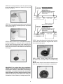
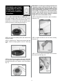
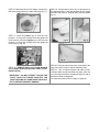
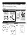
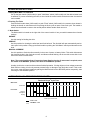
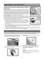
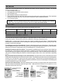
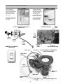
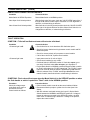
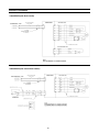
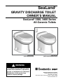
SeaLand ® Gravity discharge Toilet Owner’s Manual SeaLand® 3300, 3400 Series All-Ceramic Toilets 3300 Series (with flush handle) 3400 Series (with remote flush switch) ! WARNING This manual must be read and understood before installation, adjustment, service, or maintenance is performed. Modification of this product can result in property damage. Dometic Sanitation Corporation 13128 State Rt 226, PO Box 38 Big Prairie, OH 44611 SeaLand Product Customer Service: 1-800-321-9886 www.DometicUSA.com Table of Contents Toilet Model Identification . . . . . . . . . . . . . . . . . 2 Ordering Parts . . . . . . . . . . . . . . . . . . . . . . . . . 2 Toilet Dimensions . . . . . . . . . . . . . . . . . . . . . . . 3 Toilet Installation Instructions. . . . . . . . . . . 3 - 6 Remote Flush Switch Installation . . . . . . . . . . . 7 Important Information Before Operation . . . . . . 8 Electronic "Flush and Forget" Operation. . . . . . 8 Toilet Controls. . . . . . . . . . . . . . . . . . . . . . . . . . 8 Operating Instructions. . . . . . . . . . . . . . . . . . . . 9 Automatic Flush Operation Timing Chart. . . . . 9 Proper Cleaning and Maintenance . . . . . . . . . 10 Manual Flush Operation . . . . . . . . . . . . . . . . . 10 Winterizing . . . . . . . . . . . . . . . . . . . . . . . . . . . 11 Spare Parts. . . . . . . . . . . . . . . . . . . . . . . . . . . 11 Deodorants and Special Tissue . . . . . . . . . . . 11 Flush Mechanism Components. . . . . . . . . . . . 12 Electrical Specifications. . . . . . . . . . . . . . . . . . 13 Troubleshooting. . . . . . . . . . . . . . . . . . . . 14 – 17 Wiring Diagrams . . . . . . . . . . . . . . . . . . . . . . . 18 Customer Service . . . . . . . . . . . . . . . . . . . . . . 19 Limited Warranty . . . . . . . . . . . . . . . . . . . . . . 20 WARNING – ELECTRICAL SYSTEM. Turn off electrical power before servicing. WARNING – MOTOR STARTS AUTOMATICALLY. Turn off electrical power before servicing. Read and understand the complete contents of this manual before operating or servicing the toilet. Failure to follow these precautions may result in damage to the toilet. Toilet Model Identification The model identification label is located on the inside wall of the toilet under the access cover. It will show the model number and serial number. Ordering Parts Dometic is ready to assist you in the event service is required. Before calling, please have the following information available. Your cooperation in having this information ready is appreciated and allows us to better meet your needs. Please refer to the Parts Distributor list in the Customer Service section. 1. Toilet Model Number 2. Serial Number 3. Part Number, Description and Quantity (see Parts List) SeaLand and Flush and Forget are registered trademarks of Dometic Corporation. toilet Dimensions Dimensions may vary ±3/8-inch (13mm). Toilet INSTALLATION INSTRUCTIONS System Requirements: • 2 GPM (10.6 lpm) or larger water pump. • 1/2-inch (12.7 mm) water line terminating in 1/2-inch MPT fitting (to connect to toilet water supply hose). • 4-bolt floor (closet) flange. SeaLand flanges available include 3-inch spigot, socket, MPT, or 45-degree swivel socket. •12 VDC through 7- or 8-amp fuse or circuit breaker. Use 14-gauge stranded copper wire. IMPORTANT: If replacing an existing gravity-discharge toilet, make sure the center of the existing discharge flange is at least 11-1/4 inches from the back wall, then proceed to Step 5 for proper positioning of water line and electrical wiring. STEP 1: Carefully unpack the toilet bowl, rear access lid and floor flange adapter. CAUTION: HANDLE THE VITREOUS CHINA TOILET AND ACCESS LID WITH CARE. SET THE LID IN AN AREA WHERE IT CANNOT BE BROKEN. PLACE LID ON TOILET ONLY AFTER TOILET INSTALLATION IS COMPLETE. STEP 2: Position the ceramic bowl in the space intended. Confirm that adequate clearance is available for using the flush handle and opening the seat and lid. STEP 3: Mark the floor at the rear corners of the toilet bowl (fig. 1). Measure the distance between the two marks and divide by 2 to find the toilet centerline. Mark the floor at the rear wall for the centerline. STEP 4: Place a carpenter’s square against the back wall, and draw a center line on the floor at least 14 inches (356 mm) long (fig. 2). Mark the centerline for the floor flange at 11-1/4 inches (286 mm) from the wall (fig. 3). Fig. 1 Fig. 2 Fig. 3 STEP 5a: For through-the-floor water line and electrical wires, mark another centerline 6 inches (152 mm) from the back wall (fig. 4). Below-Floor Installation Fig. 4 STEP 5b: For through-the-wall water line and electrical wires, mark a centerline 8 inches (203 mm) up from the floor centerline (fig. 5). Above-Floor Installation Fig. 5 STEP 6: Make a 4-3/4 inch (121 mm) diameter hole (for most floor flanges) or a 5-1/8 inch (130 mm) diameter hole (for swivel joint floor flange) at the centerline mark furthest from the wall. Make a 1 inch (25 mm) hole at the mark closer to the wall for the water line and electrical wires (fig. 6). STEP 7: Insert floor flange into larger hole and secure to the floor with #12x3/4-inch long flat head wood or sheet metal screws (fig.7). Fig. 7 STEP 8: Route 1/2-inch (13mm) PEX tubing through the smaller hole and install a PEX 1/2-inch MPT fitting (fig. 8). Fig. 6 NOTE: A water shut-off valve should be installed in the water line to the toilet for maintenance requirements. IMPORTANT: The prefered floor flange installation method is to mount the floor fIange directly on the finished floor. However, if the bottom of floor flange and bottom of ceramic toilet must be mounted at different heights, the floor flange must be mounted within 3/8 inch (10 mm) of the bottom of the toilet (see illustrations in next column) or leakage may result. Fig. 8 IMPORTANT: If replacing an existing toilet that uses a 2-bolt floor flange, drill two 5/16-inch dia. holes in old floor flange that align with two additional holes in floor flange adapter. Use two #10 or 12 x 1-1/2-inch wood screws and washers for these drilled holes, and two T-bolts with flat washers and nuts to fasten flange gasket and floor flange adapter to old floor flange. Do not use old hardware or seal. FOR MODEL 3400 TOILET WITH REMOTE SWITCH OPERATION, see page 7 for wall switch installation instructions. STEP 13: Temporarily set the toilet in place on the floor flange (fig. 14). STEP 9: WITH THE ELECTRICAL POWER OFF, route #14 gauge stranded copper wire from 12 VDC ground and positive 12 VDC from the fuse panel through a 7- or 8-amp fuse or circuit breaker. Leave at least 30 inches (762 mm) of wire for connecting to toilet (fig. 9). Fig. 9 Fig. 14 STEP 10: Connect the holding tank to the bottom of the discharge flange. STEP 14: Mark the holes for the two toilet mounting bolts (fig. 15). STEP 11: Slide the four T-bolts into the slots of the floor flange. Install the flange gasket over the T-bolts (fig. 10). Fig. 10 Fig. 15 STEP 15: Pick up toilet and set aside. Drill 3/16-inch pilot holes in the floor (fig. 16). STEP 12: Install floor flange adapter with words “THIS SIDE UP” facing up. Tighten adapter to floor flange using four flat washers and hex nuts. Tighten in criss-cross pattern (fig. 11). Fig. 11 Fig. 16 STEP 19: Set the toilet in place (fig. 19) and secure to floor with the #14x2-1/2 inch long lag bolts (fig. 20). Install decorative bolt caps by pushing them onto bolt heads (fig. 21). STEP 16: With toilet close to floor flange, connect flexible water supply hose to the water line fitting (fig. 17). Fig. 17 STEP 17: Insert the positive (+) 12 VDC wire into position 1 of the green terminal block and tighten the screw securely. Insert the negative (-) 12 VDC wire into position 2 of the green terminal block and tighten the screw securely (fig. 18). Fig. 19 Fig. 20 Fig. 18 Fig. 21 STEP 20: Place the rear access cover on the back of the toilet. Press down firmly to seat the fastening strips. STEP 18: REMOVE RED CAP FROM MIDDLE OF FLANGE ADAPTER BEFORE FINAL TOILET INSTALLATION. STEP 21: Turn on electrical power and water to toilet. Lift flush handle and fill toilet bowl with water. Wait one hour, then inspect the floor around and under the rear of the toilet for leaks or dampness. IMPORTANT – DO NOT ATTEMPT TO SLIDE THE TOILET OVER THE FLANGE ADAPTER. THE TOILET MUST BE SET DOWN OVER THE ADAPTER TO PREVENT POSSIBLE DAMAGE. If no leaks are present, toilet is ready for operation. Model 3400 Remote flush switch INSTALLATION 3400 series toilets feature a remote flush switch to control the “Flush” and “Add Water” functions. Follow the instructions below for switch installation. STEP 1: Select a location for the switch. 8 feet of cable (2.4 m) is provided. You may need to supply more wire, depending on how far you locate the switch from the toilet. STEP 2: Cut an opening 1-1/4” wide x 1-5/8” high (see diagram at right). Cover outline STEP 3: If installing the switch in a shallow wall, you may need to use the spacer between the wall and the switch assembly cover to allow space for the wire connectors. If so, route the cable through the spacer before proceeding to the next step. STEP 4: Route the 3-conductor cable through wall cut-out and on to toilet. Cable can be routed with water supply line and power wires (see page 5, Step 9). Leave a minimum of 30 inches (.76m) of cable to allow easy wiring at toilet. 1-5/8 inch (41 mm) STEP 5: Fasten the switch assembly to the wall with the #6x1” screws (included), making sure to install with the label “THIS SIDE UP” on top. Otherwise, the “Flush” and “Add Water” functions will be reversed. 1-1/4 inch (32 mm) STEP 6: Snap cover onto switch assembly to complete switch installation on wall. STEP 7: WITH THE ELECTRICAL POWER OFF, connect the red, black and white wires from the switch to the red, black and white wires connected to the 11, 12 and 13 terminals on the control module. See page 6, Step 17 for other wiring procedure. REMOTE FLUSH SWITCH COMPONENTS Spacer outline Important Information Before Operation 1. Fill freshwater tank and add deodorant to holding tank through toilet bowl. 2. Make sure all guests understand the operation of the toilet system. 3300 models: Follow instructions below. 3400 models: "Add Water" and "Flush" are clearly marked on the remote switch. See more information below. 3. Shut off the toilet system before servicing and do not leave the vehicle with toilet system circuit breaker on. 4. Never use drain openers, alcohol, solvents, etc. in the toilet. 5. If the toilet does not function properly, refer to the Troubleshooting section of this manual and repair as necessary. If problem persists, contact your local SeaLand product dealer or see the Customer Service section of this manual. eLECTRONIC fLUSH AND fORGET® oPERATION FLUSH HANDLE TOILET 1. To add water to the toilet before using (if necessary), raise flush handle until desired water level is reached. (Water flow will stop automatically after a pre-programmed period of time). 2. To flush toilet, press flush handle down. Water will flow into bowl for two seconds, then flush ball will open. Toilet will not flush again until water refill cycle is complete. REMOTE FLUSH SWITCH TOILET 1. To add water to bowl, press top part of switch. 2. To flush, press bottom part of switch. DO NOT FLUSH FOREIGN OBJECTS THROUGH TOILET Do not dispose of sanitary napkins or other non-dissolving items in toilet, such as facial tissue or paper towels. These items can cause plugging of the system. toilet controls ACCESS COVER ADD WATER TO BOWL CONTROL SWITCH OFF FLUSH HANDLE (3300 models) OFF FLUSH Figure 1 REMOTE FLUSH SWITCH (3400 models) OPERATING INSTRUCTIONS 1. Adding More Water To Toilet Bowl Pull up the flush handle (3300 model) or push "Add Water" switch (3400 model) until the desired water level is attained. To prevent overflowing the toilet, a timer inside the control module limits the amount of water that can be added. 2. Flushing The Toilet Push the flush handle down (3300 model) or push "Flush" switch (3400 model) for a moment, then release it. Holding the handle or switch down will not prolong the flush cycle nor start a new flush cycle. The handle or switch must be allowed to return to the neutral position before another flush can occur. 3. Mode Switch The Mode switch is located on the right side of the control module. It lets you switch between three function settings: NORMAL Use this setting for flushing the toilet. SERVICE Use this position for cleaning the toilet bowl and flush ball seal. The flush ball will open automatically and remain open in this position. Lifting up the flush handle or pushing the "Add Water" switch provides water to the bowl. MANUAL OVERRIDE Use this position to flush the toilet manually in the event of power or battery failure. This switch disconnects the electronic brake in the flush valve motor, and allows manual flushing via the override access hole in the side of the vitreous ceramic base. Note: The control module allows 15 seconds of water flow for cleaning. If more water is required, return the switch to the NORMAL position, then back to the SERVICE position. A safety circuit in the control module monitors flush ball operation. If foreign objects or low voltage prevent the flush ball from closing, this circuit prevents personal injury or damage to the flush valve motor. If this condition occurs, reset the control module by placing the Mode switch into the SERVICE position temporarily, then returning it to the NORMAL position. Automatic Flush Operation Timing Chart Flush and Forget® Cycle Time Water Valve Water flow Flush Valve Opening Held Open Closing 0 1 2 3 4 5 6 7 8 9 Flush Cycle In Seconds “Flush” Time “Add Water” Time 10 11 12 13 14 15 16 Proper Cleaning – Toilet Bowl and Seal The SeaLand toilet should be cleaned regularly for maximum sanitation and operational efficiency. You can clean it just as you would a household toilet. Do not use caustic chemicals, such as drain-opening types, as they will damage the seals. BOWL CLEANING: For stubborn stains, use SeaLand Toilet Bowl Cleaner (Fig. A). It’s manufactured especially for use with SeaLand toilets. In certain locations where water is hard, a build-up of lime may dull the toilet bowl finish. Restore the shine with this cleaner. If you cannot find our brand in your area, contact SeaLand Product Customer Service for your nearest dealer. If it is not available, you can also use Bar Keepers Friend® cleanser. It is not necessary to vigorously scrub with either product. Please follow label instructions. Fig. A SEAL CLEANING: After an extended time, mineral deposits from hard water can build up under the edge of the rubber bowl seal, resulting in a slow leakdown of water from the bowl. To prevent this mineral build-up, periodically clean under the bowl seal with SeaLand Toilet Bowl Cleaner (Fig. B). 1. Put Mode switch in SERVICE position. Flush ball will open automatically. 2. Apply cleanser onto a cleaning tool (small brush, etc.), and scrub under the seal. Make sure to push bristles between bottom of seal and top of flush ball surface to scrub all parts of seal that come into contact with flush ball. Fig. B 3. Wait 2-3 minutes. 4. Pull up on flush handle or push "Add Water" switch to let water flow into bowl. Use cleaning tool and water to rinse away cleanser and loosened deposits. You can add water for up to 15 seconds in the Service position. 5. Put Mode switch in NORMAL position. Water will flow for a few seconds, then flush ball will close automatically. Water will continue flowing into bowl, making it ready for the next flush. ® Bar Keepers Friend is a registered trademark of SerVaas Laboratories Inc. Manual Flush Operation In the event of an electrical failure, the flush ball of the toilet can be manually opened to clear the bowl. We recommend using a long-neck screwdriver or 7/16-in. socket for the operation shown below. NEVER PRY OPEN THE FLUSH BALL FROM INSIDE THE TOILET BOWL. Damage to the flush ball and bowl seals may result. 1. Remove access cover from top of ceramic toilet. Place Mode Switch in the "Manual Override" position. This disconnects flush valve motor brake from electrical circuit. 3. Insert screwdriver or 7/16-in. socket through access hole and onto hex head. Manual Override position 4. Turn screwdriver or socket counter-clockwise. This will open flush ball and allow bowl contents to clear. After bowl is clear, turn screwdriver or socket clockwise to return flush ball to original position. 2. Locate hole on side of ceramic toilet. This allows access to the flush valve motor drive arm. NOTES: Water will not enter the toilet bowl during manual flush operation. Place Mode Switch in the "Normal" position before returning to automatic operation. 10 Winterizing At the end of each traveling season, the SeaLand toilet system must be winterized for storage. The following procedure should be used: 1. Pump out waste holding tank. 2. Thoroughly flush toilet system with fresh water. 3. Drain freshwater tank. 4. Add freshwater antifreeze to freshwater tank. 5. Flush freshwater antifreeze and water mixture through toilet and into the waste holding tank. Each installation is different so amounts may vary. User discretion is required to assure adequate protection. 6. Turn off electrical power. CAUTION: The use of freshwater antifreeze that contains alcohol will result in damage to your sanitation system. Only use propylene glycol freshwater antifreeze that does not contain alcohol. Spare Parts It is recommended that the following spare parts be kept available at all times: Description Flush Ball Seal Kit Flush Ball Part Number Quantity Description Part Number Quantity see parts list see parts list 1 1 Water Valve Vacuum Breaker Assembly see parts list see parts list 1 1 Deodorants and Special Tissue Your SeaLand toilet requires the regular addition of a deodorant product to reduce malodors and to help break down holding tank contents. Several factors should be considered in selecting a deodorant product. Liquid or Dry: Liquid products obviously work more quickly by readily going into solution. Granulated powder formulations, on the other hand, have the advantage of requiring less storage space and are less likely to leak if the package is inadvertently damaged. Formaldehyde versus Non-Formaldehyde: Dometic manufactures both types of deodorants. Generally speaking, formaldehyde formulas control odor very effectively at all temperatures and with all degrees of water hardness. SeaLand Environment-Friendly brand, which is formaldehyde free, is similarly effective. How Much Deodorant and How to Add It: The deodorant is added directly into the toilet bowl, then flushed into the holding tank. Follow bottle or package instructions. Conditions of extremely warm weather, longer waste holding time and larger tank capacities may require more deodorant treatment. Also, to maintain optimum efficiency in odor control, the waste holding tank should be cleaned thoroughly at least once or more each season, depending on use. Why Not Use Household Toilet Paper in Your SeaLandToilet? Household tissues often contain adhesives which bond together the paper fibers from which the tissue is made. The adhesives prevent the tissue from breaking apart, and their use in “ultra-low flow” systems can cause system clogging. SeaLand tissue is especially designed for use in low water toilet systems. Its rapid dissolving properties minimize the amount of residual paper in the holding tank and allow deodorizers to work more efficiently. SeaLand versus Other Brands: SeaLand constantly strives to provide our system owners with effective products that have minimal environmental impact and good value. Many deodorant products do not measure up to our standards of performance and value. ® SeaLand Rapid-Dissolving Toilet Tissue Four 400-sheet rolls Part No. 379441204 SeaLand® Granulated Deodorant Six 2-oz. pouches Part No. 379626002 SeaLand® Liquid Deodorant Environment Friendly 32-oz. bottle Part No. 379114032 SeaLand® Liquid Deodorant Two 8-oz. bottles Part No. 379224008 11 Flush Mechanism Components 3. Lift ceramic toilet straight up from base and set it down just in front of floor flange. Turn off water to toilet and disconnect flexible water line. Disconnect power wires and/or flush switch wires if necessary. 1. To access base assembly components, remove decorative screw caps and unscrew two bolts that hold ceramic toilet to floor. 2. Remove access cover from top of ceramic and set it aside. Control module FLUSH HANDLE COMPONENTS (3300 series) Flush Handle Mode Switch Input for Flush Cable Flush Switch Flush Handle Cable Input for Power Cable REMOTE FLUSH SWITCH (3400 series) Water Valve Flush Ball Input for Base Assembly Cable BASE ASSEMBLY COMPONENTS (under ceramic toilet) Flush Valve Motor Motor Drive Arm Open Limit Switch Rotor Arm Closed Limit Switch Base Assembly Cable Flexible Water Supply Hose 12 toilet system electrical specifications 12VDC Maximum standby current (amps): .070 Maximum operating current (amps): 6.5 Flush motor locked rotor current (amps): 14.5 Maximum voltage 15 Minimum voltage:10 Input power wire size14 ga. All other wires size:18 ga. Fuse size (amps) 8 13 troubleshooting A volt/ohmmeter (VOM) and the Toilet Wiring Diagram may be required for this section. Caution: Portions of this section will require that power be applied to the toilet. Keep hands away from the flush ball, motor drive arm and rotor shaft to prevent personal injury during testing and troubleshooting. The control module uses a microprocessor to provide all the automatic and timing functions. The module is under the access cover. The control module has input and output status lights that can be used in troubleshooting the toilet. The program in the microprocessor monitors the input and output signals during a normal flush cycle. If the inputs or outputs do not follow the commands of the program, then the microprocessor may go into a "standby" mode and flash an "error code.” The microprocessor is reset by placing the Mode switch in the SERVICE position temporarily, then returning the switch to the NORMAL position. A safety circuit in the control module monitors flush ball operation. If foreign objects or low voltage prevent the flush ball from closing, this circuit prevents personal injury or damage to the flush valve motor. If this condition occurs, reset the control module by placing the Mode switch into the SERVICE position temporarily, then returning it to the NORMAL position. Status Light 1 Valve Closed 2 Valve Open 3 Flush 4 Add Water 5 Water Valve 6 Status 7 +5V Function Flush valve Closed Limit Switch engaged. Flush valve Open Limit Switch engaged. Flush handle or wall switch in "Flush" position. Flush handle or wall switch in "Add Water" position. Electric water valve energized. Status/error codes Input power Color Green Green Green Green Green Green Green ERROR CODES No. of Flashes 1 1 2 Pause .5 sec. 2 sec. 2 sec. Condition Mode Switch in SERVICE position Valve Open Limit Switch problem Valve Closed Limit Switch problem 14 LED 7 +5V LED 6 STATUS LED 5 WATER VALVE LED 4 ADD WATER LED 3 FLUSH LED 2 VALVE OPEN LED 1 CONTROL MODULE STATUS LIGHTS VALVE CLOSED Status Light 6 6 6 troubleshooting (cont’d) ERROR CODE CORRECTIVE PROCEDURES Condition Corrective Action Mode Switch in SERVICE position. Return Mode Switch to NORMAL position. Valve Open Limit Switch problem. With the flush valve fully open, check the “Valve Open” status light. If the light is off, then the Valve Open Limit Switch is out of alignment or defective, or related wiring is defective. Valve Closed Limit Switch problem. With flush valve in the fully closed position check the “Valve Closed” status light. If the light is off, then the Valve Closed Limit Switch is out of alignment or defective, or related wiring is defective. TOILET OPERATION SYMPTOM 1. Toilet will not flush and water will not enter toilet bowl. Condition Corrective Action +5V status light is off: • Check toilet fuse or circuit breaker at DC distribution panel. • Check for loose or defective wiring between control module and DC distribution panel. • Check for reverse polarity of input power to control module. • If all of above check OK, replace control module. +5V status light is on: • Input power must be 10 volts or higher. • Check control module for error codes. • Put Mode Switch in Service position. If flush valve opens, go to next step. If the flush valve does not open, go to Symptom 2. • Put the Mode Switch in Normal position and push handle or switch to "Flush" while observing “FLUSH” status light. The “FLUSH” status light must come on when the switch is pushed and go off when the switch is released. If the “FLUSH” status light did not follow commands of switch, then flush switch or related wiring is defective. SYMPTOM 2. Flush valve will not open when the Mode Switch is in the SERVICE position or when the flush handle or switch is pushed to "Flush" while in the NORMAL position. Procedure Corrective Action Check the voltage output to the flush valve motor at pins 9 and 10 on the control module as follows: • Pull the control module out as far as the control cables will allow. • Disconnect either the purple or yellow wire from the Open Limit Switch. • With DC voltmeter test leads across pins 9 and 10, flip the Mode Switch between the Normal and Service positions. If voltage is present for about two seconds in the Service position, the flush valve motor or related wiring is defective. If voltage is not present, replace the control module. 15 troubleshooting (cont’d) SYMPTOM 3. Flush valve will not close. Condition/Procedure Corrective Action Mode Switch is in SERVICE position: • Return switch to the “Normal” position. Foreign object prevents the flush valve from closing and the safety circuit locked flush valve in open position: • Reset the control circuit by putting the Mode Switch in the Service position temporarily, then returning to the Normal position. If the flush valve did not close, go to next step. Check the voltage output to the flush valve motor at pins 9 and 10 on the control module as follows: • Pull the control module out as far as the control cables will allow. • Disconnect either the orange or green wire from the Closed Limit Switch. • With DC voltmeter test leads across pins 9 and 10, flip the Mode Switch between the SERVICE and Normal positions. If voltage is present for about two seconds in the Normal position, the flush valve motor or related wiring is defective. • If voltage is not present, replace the control module. SYMPTOM 4. Water will not enter toilet bowl during a flush and when the flush handle is raised or the flush switch is pushed to “Add Water”. Procedure Check the “WATER VALVE” status light while pushing the "Flush" switch on the control panel: Corrective Action • If the “WATER VALVE” status light comes on, the water valve filter screen may be plugged with debris, or the water valve or its related wiring is defective. • If the “WATER VALVE” status light remains off, replace the control module. • If voltage is not present, replace the control module. SYMPTOM 5. Flush valve will not open when Mode Switch is in the “Service” position but opens during a normal flush cycle. Corrective Action • Replace control module. 16 troubleshooting (cont’d) SYMPTOM 6. Water will not stay in bowl. Condition/Procedure Corrective Action Put Mode Switch in “Service” position: • Clean underside of flush valve ball seal of dirt and debris. Worn or damaged flush valve ball and seal: • Remove toilet from floor and remove base assembly from toilet and replace flush valve ball and seals. SYMPTOM 7. Water will not shut off and overflows the toilet. Procedure Corrective Action Check the “WATER VALVE” status light: • If the light is on when not flushing the toilet or adding water, replace the control module. If the light responds correctly, go to next step. • Dirt or debris lodged in the water valve seal. Remove the toilet from the floor, disassamble and clean water valve. • Replace water valve. SYMPTOM 8. Water is leaking from under the toilet. Procedure Remove the toilet from the floor and inspect the following with both water and electrical power applied: (Place a container under the base assembly to catch any water during the inspection procedure.) • Water hoses and fittings, water valve assembly • Ceramic toilet bowl • Upper base seal • Flush valve ball rotor shaft shaft • Base assembly 17 Wiring Diagrams 3300 SERIES (with flush handle) 3400 SERIES (with remote flush switch) 18 CUSTOMER SERVICE There is a strong, worldwide network to assist in servicing and maintaining your sanitation system. For the Authorized Service Center near you, please call from 8:00 a.m. to 5:00 p.m. (ET) Monday through Friday. You may also write us at Dometic Corp., P.O. Box 38, Big Prairie Ohio 44611. You may also contact or have your local dealer contact the Parts Distributor nearest you for quick response to your replacement parts needs. They carry a complete inventory for the SeaLand product line. Telephone:1 800-321-9886 U.S.A. and Canada 330-496-3211 International Fax: U.S.A. MASTER SANITATION DISTRIBUTORS U.S.A. – North Central (IL, IN, KY, MI, OH) Midwest Marine Supply 24300 Jefferson Ave. St. Clair Shores, MI 48080 Tel: 586-778-8950 800-860-1540 Fax: 586-778-6108 E-mail: [email protected] U.S.A. - Northeast (CT, DE, DC, MA, MD, ME, NH, NJ, NY, PA, RI, VA, VT, WV) Northeast Marine Sanitation 69 Florida Street Farmingdale, NY 11735 Tel: 631-752-7606 800-352-4323 Fax: 631-752-7615 888-283-7606 E-mail: [email protected] U.S.A. - Northwest (AK, ID, MT, OR, WA, WY) Marine Sanitation, Inc. 1900 N. Northlake Way,Suite 121 Seattle, WA 98103 Tel: 206-633-1110 800-624-9111 Fax: 206-633-0317 E-mail: [email protected] U.S.A. - South Central (AR, KS, LA, MO, MS, NM, OK, TX) AER Supply P.O. Box 349 2301 Nasa Road #1 Seabrook, TX 77586 Tel: 281-474-3276 800-767-7606 Fax: 281-474-2714 E-mail: [email protected] 330-496-3097 U.S.A. and Canada 330-496-3220 International U.S.A. - Southeast (AL, FL, GA, NC, PR, SC, TN, VI) Environmental Marine 111 S.W. 23rd Street, Suite A Fort Lauderdale, FL 33315 Tel: 954-522-2626 800-522-2656 Fax: 954-522-5152 E-mail: [email protected] U.S.A. - Southwest (AZ, CO, NV, UT, CA-south) Ardemco Marine Specialties 778 West 17th Street Costa Mesa, CA 92627 Tel: 949-722-7672 800-253-0115 Fax: 949-642-9582 E-mail: [email protected] U.S.A. – Upper Midwest (IA, MN, NE, ND, SD, WI) PowerHouse Marine 518 Logan La Crosse, WI 54603 Tel: 608-784-9580 888-752-4539 Fax: 608-784-8422 E-mail: [email protected] U.S.A. – Northern California Fox Marine 6545 Caballero Buena Park, CA 90620 Tel: 800-826-2873 Fax: 714-690-1511 E-mail: [email protected] 19 CANADA MASTER SANITATION DISTRIBUTORS Canada - East Transat Marine 70 Ellis Drive Unit 1 Barrie, Ontario L4N 8Z3 Canada Tel: 800-565-9561 705-721-0143 Fax: 705-721-0747 Email: [email protected] Canada - West Western Marine Company 1494 Powell Street Vancouver, BC V5L 5B5 Tel: 604-253-7721 800-663-0600 Fax: 604-253-2656 800-663-6790 E-mail: [email protected] INTERNATIONAL SEALAND SANITATION SYSTEM DISTRIBUTORS Call 1-800-321-9886, email us at [email protected], or visit www.dometicusa.com for the distributor nearest you. ��������������������������������������������������������� Manufacturer’s Two-Year and Ten-Year Limited Warranties Dometic Corporation warrants, to the original purchaser only, that this SeaLand® gravity discharge toilet, if used for personal, family or household-like purposes, is free from defects in material and workmanship for a period of two (2) years from the date of purchase. Dometic also warrants, to the original purchaser only, that the vitreous china toilet bowl will not discolor, stain, scratch or craze for a period of ten (10) years if used for personal, family or household-like purposes, and is regularly cleaned as described in the product’s owner’s manual. If this Dometic product is placed in commercial or business use, it will be warranted, to the original purchaser only, to be free of defects in material and workmanship for a period of ninety (90) days from the date of purchase. Dometic reserves the right to replace or repair any part of this product that proves, upon inspection by Dometic, to be defective in material or workmanship. All labor and transportation costs or charges incidental to warranty service are to be borne by the purchaser-user. EXCLUSIONS IN NO EVENT SHALL Dometic BE LIABLE FOR INCIDENTAL OR CONSEQUENTIAL DAMAGES, FOR DAMAGES RESULTING FROM IMPROPER INSTALLATION, OR FOR DAMAGES CAUSED BY NEGLECT, ABUSE, ALTERATION, OR USE OF UNAUTHORIZED COMPONENTS. THIS INCLUDES FAILURES WHICH MAY RESULT FROM NOT FOLLOWING THE WINTERIZATION OR CLEANING PROCEDURES AS DESCRIBED IN THIS MANUAL. ALL IMPLIED WARRANTIES, INCLUDING ANY IMPLIED WARRANTY OF MERCHANTABILITY OR FITNESS FOR ANY PARTICULAR PURPOSE, ARE LIMITED TO A PERIOD OF ONE (1) YEAR FROM DATE OF PURCHASE. IMPLIED WARRANTIES No person is authorized to change, add to, or create any warranty or obligation other than that set forth herein. Implied warranties, including those of merchantability and fitness for a particular purpose, are limited to one (1) year from the date of purchase for products used for personal, family or household-like purposes, and ninety (90) days from the date of purchase for products placed in commercial or business use. OTHER RIGHTS Some states do not allow limitations on the duration of an implied warranty, and some states do not allow exclusions or limitations regarding incidental or consequential damages; so, the above limitations may not apply to you. This warranty gives you specific legal rights, and you may have other rights which vary from state to state. To obtain warranty service, first contact your local dealer from whom you purchased this product. Dometic is a customer-driven, world-leading provider of innovative leisure products for the caravan, motorhome and marine markets. Dometic offers a complete range of air conditioners, refrigerators, awnings, cookers, sanitation systems, lighting, windows, doors and other equipment that makes leisure life more comfortable away from home. Dometic also provides refrigerators for specific use in hotel rooms, offices and for storage of medical products and wine. Dometic’s products are sold in almost 100 countries and are produced mainly in Dometic’s own production facilities around the world. Dometic has more than 4,400 employees. Dometic Sanitation Corporation 13128 State Rt 226, PO Box 38 Big Prairie, OH 44611 SeaLand Product Customer Service: 1-800-321-9886 Email: [email protected] www.DometicUSA.com ® Registered; ™ Trademark of Dometic Corporation © Dometic Corporation 600344954 5/07 20