1
Installation Instructions for
45HM IDH Max® Mortise Locks
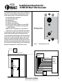
The 45HM IDH Max® Mortise Lock provides the following
features in an integrated lock, eliminating the need to
install separate sensors in and around the door frame:
■ electrified locking mechanism
■ electronic token reader
■ integrated trim
■ door status detection
■ latchbolt status detection
■ ability to exit without triggering an alarm (RQE)
■ compatibility with varied access control panels/
reader interfaces.
Note: For a list of compatible access control panels/
reader interfaces, contact your local BEST representative.
A panel interface module is provided with the lock. The
panel interface module receives token data and lock
sensor data from the lock through an RS-485 connection.
It translates this data into parallel signals, which it sends
to the access control panel/reader interface. The panel
interface module also translates control signals received
from the access control panel/reader interface and sends
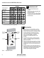
them to the lock. The figure below shows the relationship
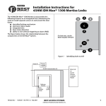
between the components in the IDH Max® system.
Power (2)
A
B
B
C
F
For hole sizes, see the
W28 Template (T81625)
G
H
G
A
Figure 1
D
Identifying holes to drill
Power
supply
RS-485 Communication (2)
Panel interface
module
Card present (1)
Field wire
harness
Wire
transfer
hinge
Lock
Sounder (2)
Reader LED (2)
Token data (2)
Strike (2)
RQE status (2)
Door & latchbolt status or
Door status (2)
Communication tamper or
Latchbolt status (2)
Power (2)
BEST ACCESS SYSTEMS
a Division of Stanley Security Solutions, Inc.
Access
control
panel/
reader
interface
Power
supply
1
Installation Instructions for 45HM IDH Max® Mortise Locks
Functions
Holes by Function
DEU/DEL
LEU/LEL NXEU/NXEL TDEU/TDEL
Holes to drill
A Forged trim
(2 holes)†
I/S O/S
Through
door
Through
door
I/S O/S
Through
door
Through
door
B Harness†
■
H Lever†
†
■
■
F Thumb turn
G Trim mounting
(2 holes)†
■
■
Through
door
Through
door
■
■
Through
door
Through
door
Through
door
Through
door
Through
door
Through
door
Because these holes pass through the mortise pocket, it is recommended that each
hole be drilled separately rather than straight through.
2
Door edge
template
Installation
template
Centerline
Centerline
Figure 1
2
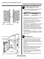
Identify holes to drill
1 Determine the lock function to be
installed.
2 Determine the inside and outside, hand,
and bevel of the door.
3 See the Holes by Function table and Figure
1 to determine the holes to be drilled for
the lock function.
I/S O/S
Through
door
Through
door
■
C Standard cylinder
D Sensor & solenoid wire
I/S O/S
Through
door
1
Align templates
Note: If the door is a fabricated hollow metal door,
determine whether it is properly reinforced to support
the lock. If door reinforcement is not adequate, consult
the door manufacturer for information on proper
reinforcement. For dimensions for preparing metal
doors, see the W29 Template – Installation
Specifications for 45HM IDH Max Mortise Locks
(T81630).
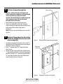
1 Separate the four templates provided on the W28
Template—Installation Template for 45HM IDH Max
Mortise Locks (T81625).
2 Position one of the door edge templates on the door,
making sure that the lock case mortise shown on the
template aligns with the mortise pocket prepared in
the door.
3 Using the centerlines on the door edge template as a
guide, position the appropriate door template on each
side of the door. You need to take the bevel into
account. Tape the templates to the door.
Aligning the templates
BEST ACCESS SYSTEMS
a Division of Stanley Security Solutions, Inc.
Installation Instructions for 45HM IDH Max® Mortise Locks
3
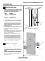
Drill wire channel through door
Hinge mortise
Caution 1: Check with your local fire marshal
before drilling a fire-rated door. Drilling through
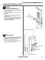
a fire-rated door may void the fire label.
Caution 2: Be careful to drill straight through the
door, making sure the drill does not break
through the face of the door.
1 Remove the hinge nearest the mortise cavity.
2 Using a 3 to 4 foot drill bit, drill a 3/8″ diameter
channel through the upper back of the mortise cavity
to the center of the nearest hinge mortise.
See Figure 3.
Note: It may be easier to drill halfway from each side of
the door.
4
Optional: Prepare door for door status
switch (for deadbolt function locks with
door sensing only)
1 Locate the centerpoint for the door status switch 2.5″
above the top of the faceplate mortise on the edge of
the door (as shown in Figure 4).
2 Drill a 1″ diameter hole 1 3/4″ deep for the door
status switch.
3 Position the drill so the tip of the bit is approximately
1″ into the hole and the bit is close to the top edge of
the hole. Then drill a 3/8″ channel at approximately a
35° angle from the door status switch hole into the
mortise cavity (as shown in Figure 4).
Figure 3
Drilling the wire channel through the door
Door status
switch hole
3/8″
channel
Figure 4
BEST ACCESS SYSTEMS
a Division of Stanley Security Solutions, Inc.
Preparing for the door status switch
3
Installation Instructions for 45HM IDH Max® Mortise Locks
5
Determine wire gauge for power
wiring
1 Calculate the total length of the power wire run
by summing:
■ The distance from the power supply to the first
door.
■ If powering more than one door daisy-chained to
the same power supply, add the total distance of
the power runs between the doors.
2 Refer to the table below to determine the minimum
wire gauge based on the number of doors sharing the
power supply and the total length of the wire run.
6
Field wiring
Door frame
Figure 6
4
Door
Running field wiring
1 door
2 doors
3 doors
4 doors
Min. wire gauge
250 ft.
125 ft.
75 ft.
60 ft.
18 AWG
400 ft.
200 ft.
130 ft.
100 ft.
16 AWG
600 ft.
300 ft.
185 ft.
150 ft.
14 AWG
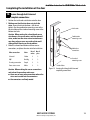
Prepare door for wire transfer hinge
and run field wiring
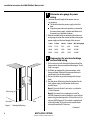
1 Drill a wire access hole through the frame side of the
hinge mortise where you removed the hinge in Task 3,
Step 1 on page 3.
2 Drill holes (or pockets) for splice connectors in the
frame and door. Refer to the hinge manufacturer’s
specifications for the hole location.
3 De-burr the holes to prevent damage to the hinge
leads.
4 Run the power field wiring from the location for the
lock’s power supply to the location for the wire
transfer hinge.
Note 1: To match the lock’s wire color, use yellow for
12 volts DC power.
Note 2: To minimize lever temperature, install an
8WTCM (temperature control module) in series with the
power and ground wiring within 20 feet of the lock. Use
only one 8WTCM per lock. This module is supplied with
electrically locked (EL) functions and is optional with
electrically unlocked (EU) functions.
– Continued
BEST ACCESS SYSTEMS
a Division of Stanley Security Solutions, Inc.
Installation Instructions for 45HM IDH Max® Mortise Locks
Configuring & installing the mortise case
5 Run the sensor wiring from the location of the access
control panel to the location for the wire transfer hinge.
To match the sensor wire colors, refer to the table below.
Wire connection
Door status sensor
Latchbolt status sensor
RQE status sensor
Color
White
Purple
Brown & Orange
No. of wires
2
2
2
Door
status
switch
Shield
7 Pull the field wiring down the wall and through the
access hole in the frame.
7
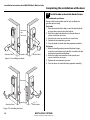
Optional: Install door status switch
(for deadbolt function locks with door
sensing only)
1 Position the shield on the door status switch with the
notch facing downwards (towards the mortise pocket).
Caution: Make sure the wires are not routed across
any sharp edges or over any surface that could
damage its sleeving.
2 Feed the wires for the door status switch into the door
status switch hole and through the channel into the
mortise cavity.
3 Insert the door status switch assembly into the door
status switch hole.
8
Figure 7
Installing the door status switch
Rotate latchbolt (if necessary)
Note: If a function specific mortise case was ordered, some
steps for configuring the case have already been
performed at the factory.
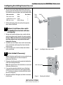
1 Determine whether you need to rotate the latchbolt to
match the handing of the door.
Note: The angled surface of the latchbolt must contact the
strike when the door closes.
2 If you need to rotate the latchbolt, insert a flat blade
screwdriver into the latch access point approximately
1/2″ into the case and press to extend the latch out of
the case. See Figure 8.
3 Rotate the latchbolt 180 degrees and allow it to retract
into the case.
Latch access point
Figure 8
BEST ACCESS SYSTEMS
a Division of Stanley Security Solutions, Inc.
Rotating the latchbolt
5
Installation Instructions for 45HM IDH Max® Mortise Locks
Configuring & installing the mortise case
9
Position hub toggles (if necessary)
1 Check whether the hub toggles are in the proper position
for the lock. See the table below and Figure 9.
Hub toggle positions
Function
Hub toggle positions
DEU/DEL, LEU/LEL, NXEU/ Inside down (always unlocked) &
NXEL, TDEU/TDEL
outside up (lockable)
Hub toggle
Figure 9
Note 1: For LH & LHRB doors, the inside is the back side of the
case and the outside is the cover side of the case.
For RH & RHRB doors, the inside is the cover side of the case
and the outside is the back side of the case. The cover is
mounted to the case with four screws.
Note 2: If the lock has an optional RQE status sensor, two RQE
status switches are installed in the mortise case. However,
only the switch for the inside of the lock needs to be
connected. Before you install the mortise case in the door,
determine whether you need to connect the ‘Case Side’ pair of
RQE wires or the ‘Cover Side’ pair of RQE wires, based on the
handing of the door.
2 To change the position of a hub toggle, remove the toggle
screw, move the toggle into the desired position, and retighten the screw.
Hub toggle
Positioning hub toggles
10
Field wire harness
Sensor & solenoid
wire hole and wires
Mortise
case
Inside of door
Inside
trim
Figure 10 Installing the mortise case (inside of door)
6
Install mortise case
1 Remove the faceplate from the mortise case, if necessary.
2 Insert the mortise case into the mortise cavity, while
feeding the sensor and solenoid wires into the mortise
cavity and out the sensor & solenoid wire hole to the inside
of the door.
Note 1: The armored front of the mortise case self-adjusts to
the door bevel.
Note 2: The field wire harness should be routed above and
behind the mortise case (depending on where the hole
through the door meets the mortise cavity).
3 Make sure there are 3″ to 4″ of slack in the field wire
harness to allow access to the control electronics circuit
board in the inside trim.
3 Secure the mortise case with the case mounting screws.
BEST ACCESS SYSTEMS
a Division of Stanley Security Solutions, Inc.
Installation Instructions for 45HM IDH Max® Mortise Locks
Installing the trim
11
Install wire transfer hinge
Note: BEST recommends one of the following concealed
electric hinges from Stanley Security Solutions. For more
information, contact your BEST representative.
Hinge
Description†
CECB 179-66
Standard weight; steel
CECB 168-66
Heavy weight; steel
CECB 191-66
Standard weight; brass
† All hinges measure 4.5″ × 4.5″ and have a 26D finish. All hinges
have two 24 AWG wires rated for 2 A at 12 or 24 volts (AC or DC)
and four 28 AWG wires rated for 1 A at 12 or 24 volts (AC or DC).
1 Trim the power and sensor wires that you pulled
through the hinge edge of the door. Leave sufficient
length to connect to the wire transfer hinge and to
allow for future splices.
2 Splice the field wires to the leads on the frame side of
the hinge, following the hinge manufacturer’s
instructions.
3 Splice the power and sensor wires from the lock to the
leads on the door side of the hinge, matching each
lead to its corresponding wire.
Note: If the lock has an optional RQE status sensor,
splice only the pair of RQE wires for the switch on the
inside of the door, which you identified in Task 9 on
page 6. Put the unused pair of RQE wires in the door.
4 Insert the wires and splice connectors into the holes or
pockets in the door and frame, being careful not to
pinch the wires. Install the wire transfer hinge.
12
Wire transfer
hinge
Door frame
Door
Figure 11 Installing the wire transfer hinge
Outside
mounting
plate
Install trim mounting plates
1 Insert the outside trim mounting plate through the
door and mortise case.
2 Position the inside trim mounting plate opposite the
outside trim mounting plate and screw them securely
in place.
Caution: Do not overtighten the trim mounting
plate screws. Overtightening may damage the
locking mechanism.
Inside
mounting
plate
Figure 12 Installing the trim mounting plates
BEST ACCESS SYSTEMS
a Division of Stanley Security Solutions, Inc.
7
Installation Instructions for 45HM IDH Max® Mortise Locks
Installing the trim
13
Cylinder
retainer
screw
Figure 13 Installing the concealed cylinder
8
Install concealed cylinder & core
(DEU/DEL and TDEU/TDEL functions
only)
1 Use a cylinder wrench to thread the cylinder into the
mortise case so that the groove around the cylinder is
even with the door surface as shown in Figure 13.
Caution: A malfunction can occur if the cylinder is
threaded in too far.
2 Secure the cylinder in the mortise case with the
cylinder retainer screw.
3 Insert the control key into the core and rotate the key
15 degrees to the right.
4 With the control key in the core, insert the core into
the cylinder.
5 Rotate the control key 15 degrees to the left and
withdraw the key.
6 The control key can be used to remove cores and
to access doors. Provide adequate security for the
control key.
BEST ACCESS SYSTEMS
a Division of Stanley Security Solutions, Inc.
Installation Instructions for 45HM IDH Max® Mortise Locks
Installing the trim
14
Install trim hole inserts and bushings
1 Insert the two trim hole inserts into the upper trim
hole on each side of the door, as shown in Figure 14.
2 Insert two bushings into the field harness & reader
wire hole on each side of the door, as shown in
Figure 14.
3 Insert a bushing into the sensor & solenoid wire hole
on the inside of the door, as shown in Figure 14.
Note: You do not need to change the positions of the
DIP switches on the control electronics circuit board
located in the inside escutcheon.
■ By default, switches 1 through 5 are set to ON. These
switches are for possible future applications.
■ By default, switches 6 and 7 are set to ON for
automatic baud rate detection. This setting lets you
determine the baud rate for communication between
the lock’s control electronics circuit board and the
panel interface module by setting DIP switches on the
panel interface circuit board. (See page 18.)
■ Switch 8 is set to OFF for locks with a swipe-type
magnetic stripe card reader, a proximity reader, or a
keypad reader; it is set to ON only for locks with an
insertion-type magnetic stripe card reader.
Trim hole
insert
Bushing
Outside of door
Trim hole
insert
Bushings
Inside of door
Figure 14 Installing the trim hole inserts and bushings
BEST ACCESS SYSTEMS
a Division of Stanley Security Solutions, Inc.
9
Installation Instructions for 45HM IDH Max® Mortise Locks
Installing the trim
15
Connect reader wire harness
1 From the outside of the door, feed the reader wire
harness connector through the field harness & reader
wire hole.
2 Temporarily rest the outside trim on the door by
inserting the trim studs into the stud holes.
Note: You can temporarily install the outside knob/lever
to hold the outside trim in place. See Task 17.
3 Connect the reader wire harness to the control
electronics circuit board in the inside trim.
4 Feed the solenoid and sensor wire harness from the
control electronics circuit board, as well as the
solenoid and sensor wires from the mortise case,
through the large opening in the inside trim.
Caution 1: When routing the reader wire harness,
make sure the reader wire harness is not routed
across any sharp edges or over any surface that
could damage its sleeving or wire insulation.
Caution 2: When connecting the reader wire
harness, make sure:
■ there are no loose wire connections where the
wires are inserted into the reader wire
connector
■ the reader wire harness connector is fully
seated in its mating connector on the control
electronics circuit board.
Reader wire harness
connector
Reader wire
harness connector
Field harness &
reader wire hole
Control electronics
circuit board
Solenoid and sensor
wire harness
Inside trim
Large opening
Outside trim
Sensor wires and
solenoid wires
Inside of door
Outside of door
Figure 15a Feeding the reader wire harness connector
from the outside trim through the door
10
Figure 15b Connecting the reader wire harness to the
control electronics circuit board
BEST ACCESS SYSTEMS
a Division of Stanley Security Solutions, Inc.
Installation Instructions for 45HM IDH Max® Mortise Locks
Completing the installation at the door
16
Secure through-bolt trim and
complete connections
1 Position the inside and outside trim onto the door.
2 Making sure that the trim does not pinch the
wires, secure the trim to the door—but do not
tighten. Use the combination mounting screw at the
top trim hole and the standard mounting screw at the
bottom trim hole.
Caution: When routing the solenoid and sensor
wire harness, the sensor wires, and the solenoid
wires, make sure the wires are not routed across
any sharp edges or over any surface that could
damage their sleeving or wire insulation.
3 Make the solenoid connection and three sensor
connections, and place the wires into the inside trim.
Wire connection
Color
No. of
wires
No. of
pins
Solenoid
Yellow
2
3
RQE
Brn/Org
2
3
Shorting connection
Purple
2
2
Door status sensor
White
2
2
Caution: When making the sensor connections
and solenoid connection, make sure:
■ there are no loose wire connections where the
wires are inserted into the connectors
■ the connectors are firmly mated.
Inside trim
Combination
mounting screw
Make these
connections.
Standard
mounting screw
Inside of door
Figure 16 Securing the through-bolt trim and
completing connections
BEST ACCESS SYSTEMS
a Division of Stanley Security Solutions, Inc.
11
Installation Instructions for 45HM IDH Max® Mortise Locks
Completing the installation at the door
17
Set screw
cap
Set screw
Outside of door
Spindles
Inside of door
Figure 17a Installing the knobs
Install inside and outside knobs/levers
For both knobs and levers
Unscrew the inside spindle one full turn to allow the
spindles to turn freely.
For knobs
1 From the outside of the door, insert the outside knob
and spindles assembly into the lockset.
2 Slide the inside knob onto the inside spindle and
secure it with the set screw.
3 Push the set screw cap into the set screw hole.
4 Tighten the trim mounting screws.
5 Turn the knobs to check that they operate smoothly.
For levers
1 With the handle pointing toward the door hinges,
insert the outside lever and spindles assembly into the
lock from the outside of the door.
2 Slide the inside lever onto the inside spindle and
secure it with the set screw.
3 Tighten the trim mounting screws.
4 Turn the levers to check that they operate smoothly.
Set screw
Outside of door
Spindles
Inside of door
Figure 17b Installing the levers
12
BEST ACCESS SYSTEMS
a Division of Stanley Security Solutions, Inc.
Installation Instructions for 45HM IDH Max® Mortise Locks
Completing the installation at the door
18
Install core
(DEU/DEL and TDEU/TDEL only)
1 Insert the control key into the core and rotate the key
15 degrees to the right.
2 With the control key in the core, insert the core into
the cylinder.
3 Rotate the control key 15 degrees to the left and
withdraw the key.
Caution: The control key can be used to remove
cores and to access doors. Provide adequate
security for the control key.
Core
Control key
Inside of door
Figure 18 Installing the core
19
Install access door
1 Making sure that the access door does not pinch
any wires, insert the tabs of the access door into its
mating slots and swing the door closed.
2 Use a T15 TORX bit driver to secure the access door
with the security screw. Tighten firmly.
Security screw
Tabs
Figure 19 Installing the access door
BEST ACCESS SYSTEMS
a Division of Stanley Security Solutions, Inc.
13
Installation Instructions for 45HM IDH Max® Mortise Locks
Completing the installation at the door
20
Strike box with magnet
Strike plate
Install strike box and strike plate
1 Insert the strike box into the mortise in the door jamb.
Place the strike plate over the strike box and secure the
strike with the screws provided.
2 Check the position of the auxiliary bolt against the
strike plate.
Caution: The auxiliary bolt must make contact
with the strike plate. The auxiliary bolt deadlocks
the latchbolt and prevents someone from forcing
the latch open when the door is closed. If the
incorrect strike is installed, a lock-in can occur.
Note: The recommended gap between the door and
jamb is 1/8″ .
Door jamb
Figure 20a Installing the strike box and strike plate
Strike plate
Auxiliary bolt
21
Figure 20b Positioning the strike
14
Optional: Install lock power supply
If you are providing a separate power supply for the
lock, instead of providing power via the panel
interface module, connect the two power field wires
(run from the wire transfer hinge) to the power supply.
Make sure power (12 volts DC) and ground are
connected properly.
Follow the instructions provided by the power supply
manufacturer. Do not plug in the power supply yet.
BEST ACCESS SYSTEMS
a Division of Stanley Security Solutions, Inc.
Installation Instructions for 45HM IDH Max® Mortise Locks
Installing the panel interface module
22
Mount panel interface module
Peel the paper off the adhesive tape affixed to the
back of the panel rail and press the panel rail into
position.
Note: Mount the panel interface module in the
enclosure with the access control panel/reader interface,
if possible.
23
Connect field wiring from wire transfer
hinge to panel interface module
Adhesive
tape
Figure 22 Mounting the panel interface module
1 Connect the two communication field wires (run from
the wire transfer hinge) to the COM+ and COM–
terminals on the panel interface circuit board.
Note: The field wire harness leads, connected to the door
side of the wire transfer hinge, are described in the table
below.
Wire
Color
Ground
Black
12 VDC
Red
Com+
Orange
Com–
Green
2 If you are providing power to the lock through the
panel interface module, connect the two power field
wires (run from the wire transfer hinge) to the 12V and
GND terminals on the panel interface circuit board.
Note: JP2 and JP3, shown in Figure 23a, are used for
manufacturing purposes only.
3 Connect the RS-485 shield wire to one of the GND
terminals on J1.
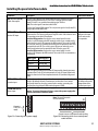
Figure 23a Panel interface circuit board
Connect to wire
transfer hinge.
Figure 23b Connecting field wiring from the
wire transfer hinge
BEST ACCESS SYSTEMS
a Division of Stanley Security Solutions, Inc.
15
Installation Instructions for 45HM IDH Max® Mortise Locks
Installing the panel interface module
24
J3
TPR
DLS
RQE
STK
Connect to access control panel/reader interface.
Figure 24a Connecting to the access control panel/
reader interface
Connect panel interface module to
access control panel/reader interface
With power removed from the panel interface circuit
board and the access control panel/reader interface,
connect the wiring between the panel interface circuit
board and the access control panel. Refer to the table
below.
Terminals
Description
Related DIP switches
TPR (on J3)
Switch-like output to the access control panel/reader interface that is
configured using DIP switch 8 to serve one of two possible functions:
Option 1—Communication tamper output: Indicates the status of the
communication connection between the panel interface circuit board and the
lock’s control electronics circuit board. By default, the output is closed to
indicate communication is OK and open to indicate communication has been
interrupted.
Option 2—Latchbolt status output: Indicates the state of the lock’s
latchbolt status switch. By default, the output is closed to indicate the latchbolt
status switch is closed.
Note: The lock’s latchbolt status switch is closed when the latchbolt is extended.
DIP switch 8
configures the function
of this output.
DIP switch 6 provides
the ability to invert the
signal.
Switch-like output to the access control panel/reader interface that is
configured using DIP switch 8 to serve one of two possible functions:
Option 1—Door status & latchbolt status output: Indicates whether the
door is secure (both the door status and latchbolt status switches are closed) or
unsecure (one or both of these switches are open). By default, the output is
closed to indicate the door is secure.
Option 2—Door status output: Indicates the state of the lock’s door status
switch. By default, the output is closed to indicate the door status switch is
closed.
Note: The lock’s door status switch is closed when the door is closed.
DIP switch 8
configures the function
of this output.
DIP switch 5 provides
the ability to invert the
signal.
Switch-like output to the access control panel/reader interface that indicates
the status of the lock’s RQE switch. By default, the output is closed to indicate
the RQE switch is closed.
Note: The lock’s RQE switch is closed when the door knob/lever is turned,
activating the switch.
DIP switch 4 provides
the ability to invert the
signal.
Input from the access control panel’s/reader interface’s strike relay, which
provides the solenoid control signal. The access control panel/reader interface
output usually has normally open (NO) and normally closed (NC) terminals, as
well as a common terminal. The common and NO terminals should be
connected to the two STK terminals on J3. To invert the operation, use the
access control panel’s/reader interface’s common and NC terminals.
The operation of the solenoid varies by lock function. See the IDH Max Lock
Service Manual (T60775).
None
Communication tamper
output or
Latchbolt status output
DLS (on J3)
Door status & latchbolt
status output or
Door status output
RQE (on J3)
Request-to-exit status
output
STK (on J3)
Strike input
16
BEST ACCESS SYSTEMS
a Division of Stanley Security Solutions, Inc.
Installation Instructions for 45HM IDH Max® Mortise Locks
Installing the panel interface module
Terminals
Description
Related DIP switches
D0, D1, & CP (on J2)
D0 is the Data 0 (Wiegand) or Strobe (ABA) token data output to the access
control panel/reader interface. D1 is the Data 1 (Wiegand) or Data (ABA)
output. D0 and D1 are capable of transmitting up to 250 feet.
Note: The strobe signal is sometimes called ‘clock’.
CP is the Card Present (ABA) output. The card present signal is low (0 volts DC)
during output of ABA token data.
None
Input for the red and green LED control signal(s) from the access control panel/
reader interface. This input is configured using DIP switch 1 for either one-wire
LED operation or two-wire LED operation.
Two-wire LED operation: Connect the access control panel’s/reader
interface’s red LED output to the RED terminal and the access control panel’s/
reader interface’s green LED output to the GRN terminal. The reader’s red LED
turns on when the access control panel/reader interface provides 0 volts DC to
the input for the red LED. The reader’s green LED turns on when the access
control panel/reader interface provides 0 volts DC for the green LED.
One-wire LED operation: Connect the access control panel’s/reader
interface’s LED output to the RED terminal. The reader’s LEDs are controlled as
shown below.
DIP switch 1
configures this input
for one-wire or twowire operation.
Token data output
RED & GRN (on J2)
Reader LED input
Input signal
0 volts DC
5 volts DC
Not driven
LED response
Green LED ON
Red LED ON
Both LEDs OFF
Note: The signals provided to the Reader LED input and the Sounder input must
be greater than 3.5 volts DC to be interpreted as a 5 volts DC signal. Signals with
voltage less than .8 volts DC are interpreted as 0 volts DC (connection to ground
(GND).
BPR & GND (on J2)
Sounder input
12V & GND (on J1)
Power input
Input for the sounder control signal from the access control panel/reader
interface. By default, the lock’s sounder turns on when the access control
panel/reader interface closes the contact for the sounder, connecting the
panel interface circuit board’s BPR terminal to ground (GND).
DIP switch 7 provides
the ability to invert the
interpretation of the
sounder input signal.
Input for 12 volts DC at .1 amp power supply.
Caution: To prevent damage and injury, connect the power supply after
all other connections have been made.
None
Note: The two NC terminals
on J2 are not used.
Connect to
12 VDC at .1 A
supply.
Connect to access control panel/reader interface.
Figure 24c Connecting to the power supply
Figure 24b Connecting to the access control panel/
reader interface
BEST ACCESS SYSTEMS
a Division of Stanley Security Solutions, Inc.
17
Installation Instructions for 45HM IDH Max® Mortise Locks
Installing the panel interface module
25
Set panel interface module DIP
switches
Set the DIP switches on the panel interface circuit
board. Refer to the table below. Default settings are
shown in boldface.
Set DIP
switches.
26
Set and connect power supply
1 Make sure that the output voltage of the power supply
for the panel interface module and lock is set to
15 volts DC or lower.
2 Make the final power supply connections.
3 Adjust the power supply output voltage to
13.8 volts DC.
Figure 25 Setting DIP switches
Feature
Option
DIP Switch Setting
Reader LED input configuration
Provides the ability to select between one-wire and two-wire LED
operation for the reader LED input.
Two-wire operation
Switch 1–ON
One-wire operation
Switch 1–OFF
Baud rate selection
Provides the ability to select the baud rate for communication between the
panel interface circuit board and the lock’s control electronics circuit board.
Note: To control the baud rate using DIP switches 2 and 3 on the panel
interface circuit board, DIP switches 6 and 7 on the control electronics circuit
board both must be set to ON (automatic baud rate detection).
38400 bps
Switch 2–OFF Switch 3–OFF
19200 bps
Switch 2–ON Switch 3–OFF
9600 bps
Switch 2–OFF Switch 3–ON
2400 bps
Switch 2–ON Switch 3–ON
Request-to-exit (RQE) status output configuration
Provides the ability to invert the request-to-exit (RQE) status signal. If DIP
switch 4 is ON, the contact is closed when the door knob/lever is turned,
activating the RQE switch.
Normally-open (NO)
Switch 4–ON
Normally-closed (NC)
Switch 4–OFF
Door status & latchbolt status / Door status output configuration
Provides the ability to invert the signal for this output. If DIP switch 8 is ON
and DIP switch 5 is ON, the contact is closed when the door is secure (the
door status switch & latchbolt status switch are closed). If DIP switch 8 is
OFF and DIP switch 5 is ON, the contact is closed when the door is
unsecured (the door status switch is closed).
Normally-closed (NC) Switch 5–ON
Communication tamper / Latchbolt status output configuration
Provides the ability to invert the signal for this output. If DIP switch 8 is ON
and DIP switch 6 is ON, the contact is closed when the communication
connection between the panel interface circuit board and the lock’s control
electronics circuit board is OK. If DIP switch 8 is OFF and DIP switch 6 is ON,
the contact is closed when the latchbolt is extended (the latchbolt status
switch is closed).
Normally-closed (NC) Switch 6–ON
18
Normally-open (NO)
Normally-open (NO)
BEST ACCESS SYSTEMS
a Division of Stanley Security Solutions, Inc.
Switch 5–OFF
Switch 6–OFF
Installation Instructions for 45HM IDH Max® Mortise Locks
Testing the installation
Feature
Option
DIP Switch Setting
Sounder input configuration
Provides the ability to invert the interpretation of the sounder input signal.
The normal input configuration interprets a closed contact as sounder ON.
Normal input
Switch 7–ON
Inverted input
Switch 7–OFF
Function of TPR terminals and DLS terminals
Provides the ability to determine the function of the TPR terminals and
DLS terminals, as shown below.
Option 1
Switch 8–ON
Option 2
Switch 8–OFF
Configuration
option
Function of
TPR terminals
Function of
DLS terminals
Option 1
(Switch 8–ON)
Communications
tamper
Door status &
latch status
Option 2
(Switch 8–OFF)
Latch status
Door status
27
Test installation
Perform the following steps to test the installation. Also,
perform any standard testing recommended by the
manufacturer of the access control panel. If you encounter
problems, see Troubleshooting the installation, on
page 20.
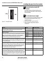
1 Check the control electronics’ green status LED and the
panel interface module’s green status LED.
Both LEDs should be blinking, indicating that the
communication connection between the panel
interface circuit board and the lock’s control
electronics circuit board is OK.
2 After performing any necessary programming for the
lock and putting the door in a locked mode, use a valid
token to access the lock.
Confirm that the red reader LED, green reader LED, and
sounder respond as expected.
The lock should allow access, verifying that the
solenoid is working.
To check that the reader is working, view the lock’s
event history and verify that the information recorded
for the token is correct.
3 Use an invalid token to attempt to access the lock.
Confirm that the red reader LED, green reader LED, and
sounder respond as expected.
The lock should deny access.
– Continued on the next page
BEST ACCESS SYSTEMS
a Division of Stanley Security Solutions, Inc.
19
Installation Instructions for 45HM IDH Max® Mortise Locks
Troubleshooting the installation
4 With the door armed, attempt to exit through the
door.
The request-to-exit (RQE) feature should let you exit
without triggering an alarm by the access control panel.
5 Remove power from the lock and check whether the
door remains locked or is unlocked.
Verify that the lock fails safe or secure, according to its
function.
6 With the door armed, hold the door open. Hold a
magnet against the edge of the door, over the door
status sensor, until the access control panel sees the
door as closed. Then remove the magnet.
Verify that the appropriate alarm response is triggered
by the access control panel, indicating that the door
status sensor is working.
7 With the door armed, hold the door open. Hold a
magnet against the edge of the door, over the door
status sensor, until the access control panel sees the
door as closed. With the magnet in place, push in the
latchbolt.
Verify that the appropriate alarm response is triggered
by the access control panel, indicating that the
latchbolt status sensor is working.
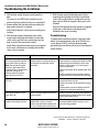
Troubleshooting
To troubleshoot installation problems, refer to the table
below. For more information, refer to the IDH Max Lock
Service Manual (T60775) and to the documentation
provided by the manufacturer of the access control panel/
reader interface.
You notice . . .
Possible causes include . . .
You should . . .
Control electronics’ green status
LED and panel interface module’s
green status LED are steadily on.
Note: You can check the control
electronic’s green status LED by
removing the access door from the
inside trim. You can see the
reflection of the LED inside the
upper-left corner of the trim.
Communication between the lock’s
control electronics circuit board and the
panel interface circuit board has been
interrupted.
Make sure DIP switches 6 and 7 on the lock’s
control electronics circuit board are both set to ON
(automatic baud rate detection) or to the same
positions as DIP switches 2 and 3 on the panel
interface circuit board.
Check the connections for all communication field
wiring.
Check the communication connections between
the field wire harness and the wire transfer hinge.
Control electronics’ green status
LED is off.
Power is not being supplied to the lock.
Make sure that the lock’s power supply is
connected to electrical service.
Check the connections for all power field wiring to
the lock.
Check the power connections between the field
wire harness and the wire transfer hinge.
Panel interface module’s green
status LED is off.
Power is not being supplied to the panel
interface module.
Check the connections for power wiring between
the panel interface module and the access control
panel (or other power source).
A ‘door forced’ alarm occurs when
someone exits through the door.
RQE wiring, and door status and/or
latchbolt status wiring, is reversed
between the panel interface module and
the access control panel/reader interface.
Refer to Connect panel interface module to access
control panel/reader interface, on page 16, and
correct the wiring problem.
© 2006 Stanley Security Solutions, Inc. and Stanley Logistics, Inc.
T81624/Rev – 1921963 ER-7991-12 Dec 2006
20
BEST ACCESS SYSTEMS
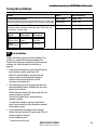
a Division of Stanley Security Solutions, Inc.