1
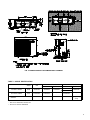
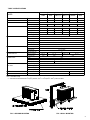
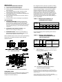
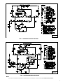
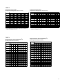
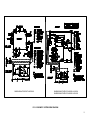
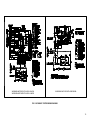
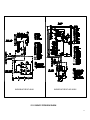
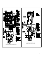
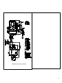
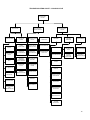
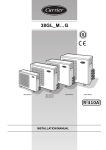
INSTALLATION, START-UP AND
SERVICE INSTRUCTIONS
Concepcion
Carrier
Air conditioning
Company
38ASB/CCARS240~600 (036~060)
AIR-COOLED CONDENSING UNIT
Philippines
CONTENTS
Safety Considerations
1
Complete Electrical Connections
Dimensional Drawing
2
Start-up
Model Identification
2
Refrigerant Charging
Specifications
3
Service and Maintenance
4
Wiring Diagram
Installation
Refrigerant Piping
4
Piping Connections
5
Trouble-Shooting Guide
5
5
5-6
6-7
7 - 13
14
FIG. 1
38ASB/CCARS240~600
(036~060) Export
SAFETY CONSIDERATIONS
INSPECTION
Installation and s ervicing of air conditioning equipment can
be hazardous due to system pressure and electrical
components. Only trained and qualified service personnel
should install, repair or service air conditioning equipment.
Observe precautions in the literature, tags and labels
attached to the unit and other safety codes. Wear safety
glasses and gloves. Use quenching cloth and have fire
extinguisher available for all brazing operations.
Check the shipment against shipping list and remove unit
from the carton and take off protective covering. If the unit
has been damaged, file claim with Transportation Company
and notify Carrier immediately.
RECEIVING
38ASB/CCARS240~600 condensing units (Fig. 1) are
shipped individually packed in carton boxes. When cartons
are individually off loaded from truck, do not roll, nor throw,
or drop the carton, to avoid damages to the content. Store
boxes upright as the symbols or the boxes indicate. Do not
stack units more than 2 high.
PROTECTION
Protect unit from damage caused by job site debris. Do
not allow dust, debris and water get into the unit.
These will damage unit’s component and unit’s
performance will be affected.
WARNING
Before installing or servicing system always turn off main
power supply. There may be more than one disconnect
switch. Electrical shock can cause personal injury.
1
FIG. 2 38ASB/CCARS024~060 DIMENSIONAL DRAWING
TABLE 1 – MODEL IDENTIFICATION
SERIES
2TR
3TR
STD
5TR
(EXPORT)
OLD MODEL NUMBER
38ASB
38ASB240BA
38ASB360BA
38ASB036BA
NEW MODEL NUMBER
CCAR
CCARS024EA
CCARS036EA
-
REMARKS
STD
38ASB600DB *
38ASB600DC **
CCARS060KA
(EXPORT)
38ASB060BA
Single phase supply
volatge
Legend:
* - Model used for 40KMC/GKX, 42GX/AR, 40LX
** - Model used for SlimPack ASBFE600BA
2
TABLE 2 SPECIFICATIONS
38ASB / CCARS
MODEL
240BA
360BA
036BA (Export) 060BA (Export)
OPERATING WEIGHT
(kg)
67
80.5
80.5
GROSS WEIGHT
(kg)
69.5
83
83
REFRIGERANT
Type
1.5
2.52
2.52
Type
LRA (A) Nominal
Running Amps (A)*
0.90
1.30
1.30
87.5
87.5
2.55
2.27
2.50
1.66
1.95
1.95
91
91
175
139
135
16.8
26.8
16.7
15.0
230V-1Ph-60Hz
Type
230V-3Ph-60Hz
Propeller
1
550
Speed (rpm)
950
Drive
Direct Drive
Type
Permanent Split Capacitor
Power Supply
230V-1Ph-60Hz
Running Amps (A)*
Rows - Fins/inch
2
Face Area (m )
1.7
2R - 15
2.5 - 15
0.379
0.536
3.5R - 15
Type
Flare
Suction, (mm) inch.
(9.5) 3/8
(15.88) 5/8
(19.05) 3/4
426 ? 20
High Cut Out (psi)
SETTINGS
3R - 15
0.654
Liquid, (mm) inch.
CONTROLS; PRESSURES SWITCH
97.5
16.8
Blade Dia. (mm)
CONNECTIONS
85
66
Number
CONDENSER COIL
85
12.6
Power Supply
FAN MOTOR
95
Hermetic
Oil Charged (l)
CONDENSER FAN
600DC
R-22
Factory charged (kg)
COMPRESSORS
600DA/DB
320 ? 10
Cut In (psi)
27 ? 4
Low Cut Out (psi)
67 ? 7
Cut In (psi)
NOMINAL POWER SOURCE
V-Ph-Hz
ABSOLUTE MIN. - MAX VOLTAGE
(V)
230V-1Ph-60Hz
230V-3Ph-60Hz
197 - 253
180 - 253
LRA : Locked Rotor Amps
?? Data rated to PNS standard at 350C (950F) Ambient, 27.00C / 19.00C (80.60F / 66.20F) Indoor Condition.
FIG. 3 GROUND MOUNTING
FIG. 4 WALL MOUNTING
3
INSTALLATION
SELECTION OF MOUNTING POSITION
1)
2)
3)
4)
5)
6)
7)
The unit should be installed outdoors.
A place where air will not be stagnant.
A place where the exhausted air will not be sucked in for
the second time.
Allow sufficient space for airflow clearance, wiring,
refrigerant piping and servicing unit. See Fig. 2.
Avoid positioning unit in such a manner that water will
pour directly onto the unit.
Do not install the unit near a source of heat, steam or
flammable gas.
Ducting of the fan inlet or discharge is not permitted.
UNIT MOUNTING
1)
MOUNTING ON GROUND – Mount on a solid, level
concrete base. If conditions or local building codes
require unit to be fastened to base, tie down bolts
should be used and fastened through slots provided in
unit’s mounting feet (Fig. 3). Do not install unit directly
on ground.
2)
MOUNTING ON AND AGAINST THE WALL – the
bracket is to be locally procured (Fig. 4).
3)
MOUNTING ON ROOF – Mount on a level platform or
frame. When multiple unit are installed, the air outlet
side should be opened as shown in Fig. 5.
When installation base is used, secure the required spacing
as per (Fig. 6). Fabricate the stand so that it will have
sufficient strength.
Run refrigerant tubes as directly as possible, avoiding
unnecessary turns and bends. Condensing unit may be
connected to evaporator sections using field-supplied
tubing of refrigerant grade, correct size and condition.
Suspend refrigerant tubes so they do not transmit
vibration to structure. Also when passing refrigerant
tubes through walls, seal opening so vibration is not
transmitted to structure. Leave some slack in refrigerant
tubes between structure and unit to absorb vibration.
The longer the piping, the lower the cooling capacity of
the unit. See table 3.
TABLE 3 – REDUCTION IN CAPACITY VS
INCREASE IN PIPE LENGTH
MODEL
PIPING LENGTH (ONE WAY)
38ASB /
CCAR
240
360 / 036
600 / 060
5m
10m
15m
20m
25m
30m
0%
1.2%
2.0%
2.8%
3.5%
4.5%
0%
1.6%
2.6%
3.6%
4.6%
5.6%
0%
2.8%
4.8%
6.7%
8.7%
10.2%
As such the following are the operating limits. Refer to
Table 4 and fig. 7.
TABLE 4 – VERTICAL AND HORIZONTAL
SEPARATION BETWEEN INDOOR
AND OUTDOOR UNIT
MODEL
MAX.
MAX.
LIQUID LINE
38ASB /
HEIGHT LENGTH MAX. ALLOWABLE MAX. ALLOWABLE
CCARS024~060 H(m)
L(m) PRESSURE DROP TEMPERATURE
LOSS ( 0C)
(kPa)
024
(20)15
360 / 036
(20)15
25
25
600 / 060
(25)15
30
151
5
0
FIG. 5 ROOF MOUNTING
Note: 1) Values shown are for units operating at 7.2 C saturated suction
0
and 35 C entering air.
2) Values in ( ) indicate a case when the outdoor unit is located at
a lower height than the indoor unit.
FIG. 7 MAXIMUM ALLOWABLE PIPING LENGTH
AND ELEVATION DIFFERENCE
FIG. 6 MINIMUM SPACING REQUIREMENT
REFRIGERANT PIPING
Size Refrigerant Lines. Consider length of piping required
between unit and evaporator, amount of liquid lift and
compressor oil return (Table 4).
Do not bury section of line set underground. If any section is buried,
refrigerant may migrate to cooled buried section during extended period of
unit shutdown. This causes refrigerant slugging and possible compressor
damage at start-up.
If either refrigerant tubing or indoor coil is exposed to atmospheric
conditions for longer than 5 minutes, it must be evacuated to 1000 microns
to eliminate contamination and moisture in the system.
4
PIPING CONNECTIONS
Complete all installation and piping work required for indoor and
outdoor units. If brazing is required pass nitrogen or other inert gas
through piping to prevent formation of cooper oxide. Unit contains R22 charge, do not open Schreader valve at this time. Leak test field
piping by pressure method.
Note: - Operation of unit on improper line voltage constitutes
abuse and could affect Carrier Warranty. Do not install
unit in system where voltage may fluctuate above or below
permissible limits.
START-UP
PRELIMINARY CHECKS:
1)
Check that all internal wiring connections are tight and all
barriers, covers and panels are in place.
Field electrical power source must agree with unit name
plate rating.
All service valves must be opened.
PIPING INSULATION
No refrigerant control device is shipped with the unit except 024
model. It is already installed in matching Fan coil units, check
carefully the indoor unit. Insulate suction line adequately (Fig. 8)
2)
3)
START SYTEM
NOTE: Model 240 need
to insulate both Suction
and liquid pipes
1.
2.
Check that field disconnect is closed.
Set room thermostat to below room temperature, and unit
compressor will start after 3 minutes delay o.
Check back pressure when compressor runs. Add charge to
keep back pressure at approximately 448kPa (65 PSIG).
3.
REFRIGERANT CHARGING
CAUTION
TO PREVENT PERSONAL INJURY, WEAR SAFETY
GLASSES AND GLOVES WHEN HANDLING
REFRIGERANT. DO NOT OVERCHARGED SYSTEM.
THIS CAN CAUSE COMPRESSOR FLOODING.
FIG. 8 PIPING INSULATION
COMPLETE ELECTRICAL CONNECTIONS
CAUTION
THE CONTROL VOLTAGE FROM THE FAN COIL UNIT
MUST BE OF 230V. DO NOT CONNECT THE POWER
SUPPLY TO THE SIGNAL
POWER – Unit is factory wired for voltage shown on name plate.
Provide adequate fused disconnect switch within sign of unit, readily
accessible, but out of reach children.
Provide for locking switch open (OFF) is advisable to prevent power
from being turned on w hile unit is being serviced.
Route power wires through opening in unit side panel and connect in
unit control box (fig. 9). Unit must be grounded.
IMPORTANT
For accurate system performance, charge by superheat method
as shown in table 5 and 6.
To check and adjust charge, follow the following procedures:1)
2)
3)
4)
5)
6)
7)
Operate unit for a minimum of 15 minutes before checking
charge.
Measure suction pressure by attaching a gauge to suction
line service port.
Measure suction line temperature by attaching a service
thermometer to unit suction line near suction valve.
Insulate thermometer for accurate readings.
Measure outdoor coil air inlet dry-bulb temperature with a
second thermometer.
Measure indoor coil air inlet wet-bulb temperature with a
sling psychrometer.
Refer to table 5. Find air temperature entering outdoor coil
& wet-bulb temperature entering indoor coil. At this
intersection, note the superheat.
Refer to table 6 . Find superheat temperature and suction
pressure, note suction line temperature.
FIG. 9 POWER WIRES TO THE SIDE OF UNIT
CONTROL CIRCUIT WIRING
Refer to wiring diagram for field supplied wiring details.
See Fig. 11 & 12.
5
REFRIGERANT CHARGING (cont)
8)
If unit has higher suction line temperature than charted
temperature add refrigerant until charted temperature is
reached.
9) If unit has lower suction line temperature than charted
temperature, bleed refrigerant until charted temperature is
reached.
10) If air temperature entering outdoor coil or pressure at
suction line charge to new suction line temperature
indicated on chart.
11) This procedure is valid independent of indoor air quantity.
SERVICE AND MAINTENACE
CAUTION
BEFORE PERFORMING RECOMMENDED MAINTENANCE
AND SERVICE, BE SURE UNIT MAIN POWER SWITCH IS
TURNED OFF. FAILURE TO DO SO MAY RESULT IN
ELECTRIC SHOCK OR INJURY FROM ROTATING FAN
BLADE.
FIG. 10 CLEANING COIL WITH WATER
LUBRICATION
Fan motor is permanently sealed lubricated bearings. Do not oil.
Compressor is supplied charged with oil. Replace oil when lost.
See table 2 for oil recharge quantity.
CLEANING COIL – Coil should be washed out with water or blow
out with compressed air. The draw thru design causes dirt and
debris to built up on the outside of the coils. Clean coil as follows:1)
2)
Turn off unit power.
Using a water hose or other suitable equipment, flush coil from
the inside to remove dirt (see Fig. 10). Be sure to flush all dirt
and debris from drain holes in base of unit. Fan motor is water
proof but it is more safe to cover or wrap motor shell with
plastic sheet (or plastic bag) to prevent water from getting
inside.
Clean coil semi-annually or as required. Fins are not continuous
through coil sections. Dirt and debris may pass between the row of
fins and become trapped between the row of fins and restrict
condenser air flow. Use a flashlight to determine if dirt or debris has
collected between coil section.
PE720113
FIG. 11 38ASB240BA, 360 & 036 / 060 (export models) WIRING
6
PE740132
FIG. 12 38ASB600DC WIRING DIAGRAM
PE740133
FIG. 13 38ASB600DB WIRING DIAGRAM
NOTE:
FOR OTHER 38ASB WIRING DIAGRAM NOT SHOWN HERE, PLEASE REQUEST COPIES FROM CCAC ENGINEERING DEPARTMENT.
7
TABLE 5
Superheat Charging Table
(Superheat Entering Suction Service Valve)
Superheat Charging Table
(Superheat Entering Suction Service Valve)
0
OUTDOOR
0
OUTDOOR
INDOOR COIL ENTERING AIR ( F) WET-BULB
INDOOR COIL ENTERING AIR ( C) WET-BULB
0
0
TEMP ( F)
50
52
54
56
58
60
62
64
66
68
70
72
74
76
TEMP ( C)
10
11.1 12.2
13.3
14.4
15.6
16.7
17.8
18.9
21.1
22.2
23.3
55
9
12
14
17
20
23
26
29
32
35
37
40
42
45
12.8
5
6.7
7.8
9.4
11.1
12.8
14.4
16.1
17.8 19.4
20.6
22.2
23.3
25
60
7
10
12
15
18
21
24
27
30
33
35
38
40
43
15.5
3.9
5.6
6.7
8.3
10
11.7
13.3
15
16.7 18.3
19.4
21.1
22.2
23.9
65
--
6
10
13
16
19
21
24
27
30
33
36
38
41
18.3
--
3.3
5.8
7.2
8.9
10.6
11.7
13.3
15
16.7
18.3
20
21.1
22.8
70
--
--
7
10
13
16
19
21
24
27
30
33
36
39
21.1
--
--
3.9
5.6
7.2
8.9
10.6
11.7
13.3
15
16.7
18.3
20
21.7
75
--
--
--
6
9
12
15
18
21
24
28
31
34
37
23.9
--
--
--
3.3
5
6.7
8.3
10
15.6
17.2
18.9
20.6
80
--
--
--
--
5
8
12
15
18
21
25
28
31
35
26.7
--
--
--
--
2.8
4.4
6.7
8.3
10
11.7
13.9
15.6
17.2
19.4
85
--
--
--
--
--
--
8
11
15
19
22
26
30
33
29.4
--
--
--
--
--
--
4.4
6.1
8.3
10.6
12.2
14.4
16.7
18.3
90
--
--
--
--
--
--
5
9
13
16
20
24
27
31
32.2
--
--
--
--
--
--
2.8
5
7.2
8.9
11.1
13.3
15
17.2
95
--
--
--
--
--
--
--
6
10
14
18
22
25
29
36.0
--
--
--
--
--
--
--
4.4
5.6
7.8
10
12.2
13.9
16.1
100
--
--
--
--
--
--
--
--
8
12
15
20
23
27
37.8
--
--
--
--
--
--
--
--
3.3
6.7
8.3
11.1
12.8
105
--
--
--
--
--
--
--
--
5
9
13
17
22
26
40.6
--
--
--
--
--
--
--
--
2.8
5
7.2
9.40 12.2
14.4
110
--
--
--
--
--
--
--
--
--
6
11
15
20
25
43.3
--
--
--
--
--
--
--
--
--
3.3
6.1
8.3
11.1
13.9
115
--
--
--
--
--
--
--
--
--
--
8
14
18
23
46.1
--
--
--
--
--
--
--
--
--
--
4.4
7.8
10
12.8
- Do not attempt to charge system under these conditions of
refrigerant slugging may occur.
20
11.7 13.3
24.4
15
- Do not attempt to charge system under these conditions or
refrigerant slugging may occur.
TABLE 6
Required Suction Tube Temperature (0C)
(Entering Suction Service Valve)
Required Suction Tube Temperature (0F)
(Entering Suction Service Valve)
SUPERHEAT
SUPERHEAT
SUCTION PRESSURE AT SERVICE PORT (psig)
61.5
64.2
67.1
70.0
73.0
76.0
79.2
82.4
85.7
0
35
37
39
41
43
45
47
49
51
2
37
39
41
43
45
47
49
51
53
4
39
41
43
45
47
49
51
53
55
6
41
43
45
47
49
51
53
55
57
8
43
45
47
49
51
53
55
57
59
10
45
47
49
51
53
55
57
59
61
12
47
49
51
53
55
57
59
61
63
14
49
51
53
55
57
59
61
63
65
16
51
53
55
57
59
61
63
65
67
18
53
55
57
59
61
63
65
67
69
20
55
57
59
61
63
65
67
69
71
22
57
59
61
63
65
67
69
71
73
24
59
61
63
65
67
69
71
73
75
26
61
63
65
67
69
71
73
75
77
28
63
65
67
69
71
73
75
77
79
30
65
67
69
71
73
75
77
79
81
32
67
69
71
73
75
77
79
81
83
34
69
71
73
75
77
79
81
83
85
36
71
73
75
77
79
81
83
85
87
38
73
75
77
79
81
83
85
87
89
40
75
77
79
81
83
85
87
89
SUCTION PRESSURE AT SERVICE PORT (KPaG)
0
0
TEMP ( F)
91
TEMP ( K)
424
443
463
483
503
524
546
568
591
0
1.7
2.8
3.9
5
6.1
7.2
8.3
9.4
10.6
1.1
2.8
3.9
5
6.1
7.2
8.3
9.4
10.6
11.7
2.2
3.9
5
6.1
7.2
8.3
9.4
10.6
11.7
12.8
3.3
5
6.1
7.2
8.3
9.4
10.6
11.7
12.8
13.9
4.4
6.1
7.2
8.3
9.4
10.6
11.7
12.8
13.9
15
5.6
7.2
8.3
9.4
10.6
11.7
12.8
13.9
15
16.1
6.7
8.3
9.4
10.6
11.7
12.8
13.9
15
16.1
17.2
7.8
9.4
10.6
11.7
12.8
13.9
15
16.1
17.2
18.3
8.9
10.6
11.7
12.8
13.9
15
16.1
17.2
18.3
19.4
10.0
11.7
12.8
13.9
15
16.1
17.2
18.3
19.4
20.6
11.1
12.8
13.9
15
16.1
17.2
18.3
19.4
20.6
21.7
12.2
13.9
15
16.1
17.2
18.3
19.4
20.6
21.7
22.8
13.3
15
16.1
17.2
18.3
19.4
20.6
21.7
22.8
23.9
14.4
16.1
17.2
18.3
19.4
20.6
21.7
22.8
23.9
25
15.6
17.2
18.3
19.4
20.6
21.7
22.8
23.9
25
26.1
16.7
18.3
19.4
20.6
21.7
22.8
23.9
25
26.1
27.2
17.8
19.4
20.6
21.7
22.8
23.9
25
26.1
27.2
28.3
18.9
20.6
21.7
22.8
23.9
25
26.1
27.2
28.3
29.4
20.0
21.7
22.8
23.9
25
26.1
27.2
28.3
29.4
30.6
21.2
22.8
23.9
25
26.1
27.2
28.3
29.4
30.6
31.7
22.2
23.9
25
26.1
27.2
28.3
29.4
30.6
31.7
32.8
8
38ASB240BA MATCHED WITH 42PGA026
38ASB240BA MATCHED WITH 42AR024 / 42GX024
38ASB360BA MATCHED WITH 42AR036 / 42GX040
FIG. 14 SCHEMATIC SYSTEM WIRING DIAGRAM
9
38ASB240BA MATCHED WITH 40GKX / KMC024
38ASB360BA MATCHED WITH 40GKX / KMC036
38ASB360BA MATCHED WITH ASBFM360BA
FIG. 15 SCHEMATIC SYSTEM WIRING DIAGRAM
10
38ASB360BA MATCHED WITH 40LX040
38ASB600DC MATCHED WITH 42AR / 42GX060
FIG. 16 SCHEMATIC SYSTEM WIRING DIAGRAM
11
38ASB600DB MATCHED WITH 40LX060
38ASB600DC MATCHED WITH 40GKX / KMC060
12
38ASB600DC MATCHED WITH ASBFE600BA
13
TROUBLE-SHOOTING CHART – COOLING CYCLE
NO COOLING OR
IN-SUFFICIENT
COOLING
COMPRESSOR RUNS
BUT CYCLES ON
INTERNAL OVERLOAD
COMPRESSOR
WILL NOT RUN
CONTACTOR OPEN
FAULTY POWER
SUPPLY
CONTACTOR
CLOSED
OUTDOOR FAN
STOPPED OR CYLING
COOLING
LOOSE LEAD AT
FAN MOTOR
COMPRESSOR
POWER
SUPPLY OPEN
OUTDOOR AIR
RESTRICTED OR
RECIRCULATING
MOTOR DEFECTIVE
RESTRICTED
DISCHARGE LINE
OPEN CONTROL
CIRCUIT
OPEN SHORTED OR
GROUNDED
COMPRESSOR
MOTOR WINDINGS
OVERCHARGE OR
NONCONDENSABLES
IN SYSTEM
COMPRESSOR
STUCK
LOW REFRIGERANT
CHARGE
HIGH SUCTION
LOW HEAD
PRESSURE
DEFECTIVE
COMPRESSOR
VALVE
HIGH SUCTION
LOW SUPERHEAT
UNIT OVERCHARGED
INCORRECT
OUTDOORFANMOTOR
CAPACITOR
DUCT RESTRICTED
INTERNAL
PRESSURE
RELIEF OPEN
INCORRECT
METERING DEVICE
DAMPERS PARTY
CLOSED
CONTACTOR OR
COIL DEFECTIVE
LOOSE ELECTRICAL
CONNECTION
LOW SUCTION
PRESSURE
DIRTY AIR FILTERS
LOSE LEADS
AT COMPRESSOR
DEFECTIVE TIME
DELAY
COMPRESSOR RUNS
BUT INSUFFICIENT
COOLING
INDOOR COIL
FROSTED
COMPRESSOR
INTERNAL
PROTECTION OPEN
LINE VOLTAGE
TO HIGH OR LOW
SLIGHTLY LOW OR
REFRIGERANT
COMPRESSOR
BEARINGS
INTERNAL
OVERLOAD OPEN
LIQUID LINE SLIGHTLY
RESTRICTED
HIGH SUPERHEAT
OPEN DISCHARGE
LINE
PRESSURE SWITCH
METERING DEVICE
RESTRICTED
INCORRECT
METERING DEVICE
INDOOR COIL
STRAINER
RESTRICTED
14
Concepcion
Carrier
Air conditioning
Company
Philippines
Concepcion Carrier Air Conditioning Company
Km. 20 East Service Road, South Superhighway,
Alabang, Muntinlupa City
Tel. No. (63)2 850 1367
Fax No. (63)2 809 9979
Website: www.carrier.com.ph
Manufacturer reserve the right to discontinue, or charge at any time, specifications or designs without notice and without incurring obligations
Form 38ASB/CCARS024~060-1IOM
Replaces: NEW
15