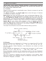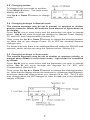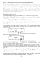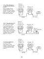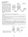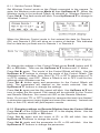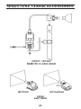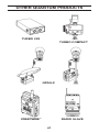
1
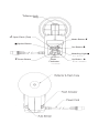
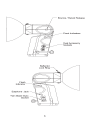
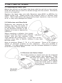
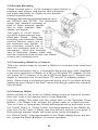
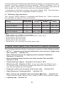
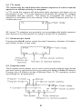
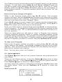
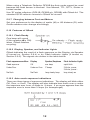
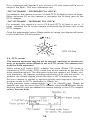
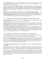
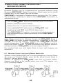
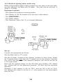
Qflash 4d
Digital Flash
®
Models T4d, X4d
Operating Instructions
For use with Quantum Turbo®, Turbo 2x2,
Turbo Compact, or Turbo Z Batteries
Quantum Instruments
Designed and manufactured in the USA
Reflector Lock
Ring
M Open Flash (Test)
Mode Button I
■ Option Button
Set Button G
Modeling Light ●
L Down Button
Flash
Indicator
Up Button J
1
TABLE OF CONTENTS
Section
1.0
2.0
3.0
4.0
5.0
6.0
7.0
8.0
9.0
10.0
11.0
Description
INTRODUCTION
WARNINGS
SETTING UP Qflash
NEW FEATURES FOR PREVIOUS Qflash OWNERS
QUICK START
Qflash OPERATION WITH QUANTUM DEDICATED
QTTL ADAPTERS
MULTIPLE Qflash OPERATION - WIRED MODE
MULTIPLE Qflash OPERATION - WIRELESS MODE
EXPOSURE COMPENSATION OF Qflash
TYPICAL LIGHTING SITUATIONS
CUSTOMER SERVICE
1. INTRODUCTION
Qflash models T4d and X4d provide professional quality lighting for both
digital and film cameras. Quantum’s proprietary QTTL® Adapters* dedicate Qflash seamlessly to your camera. Also, many features of the Qflash
“Digitals” enhance lighting control for cameras without dedicated control.
While powerful and extremely versatile, Qflash operation is intuitive and
straightforward. Advanced features for most every lighting need can be
accessed or ignored as needed.
We highly recommend reading this entire instruction manual.
Whether or not you require all of Qflash’s capability now, you will
want to know it exists when the need arises.
*QTTL D- series adapters are optional for specific makes and camera models. Please consult your dealer or www.qtm.com for the latest availability.
2. WARNINGS AND CAUTIONS
• Disconnect external power before changing the flash tube, or
connecting or disconnecting to/from cameras, power packs,
or any other equipment.
• Operate only with a flash tube in the socket.
• DO NOT TOUCH THE FLASH TUBE SOCKET WITH METAL OBJECTS.
• THIS IS A PROFESSIONAL INSTRUMENT. KEEP AWAY
FROM CHILDREN
• DO NOT ATTEMPT TO OPEN THE FLASH UNIT! DANGEROUS
HIGH VOLTAGE INSIDE!
• Repairs can be made only by a qualified Quantum service
representative.
2
3. SETTING UP Qflash
3.1 Inserting the Flash Tube
Match the red dot on the flash tube base with the red dot on the socket.
Push the flash tube in until it is seated snugly into the socket. Excessive
force is not required.
Replace the flash tube only with Quantum type QF30 or QF30uv for
Qflash model T4d. Qflash model X4d requires QF32 or QF32uv flash
tubes. Other flash tubes will not provide proper exposure, may not work
at all, or they may damage the Qflash.
3.2 Reflectors and Bare Bulb
Reflectors are secured by the
locking ring near the base of
the flash tube. Rotate the ring
in the directions shown in the
diagram to loosen or tighten the
reflectors.
When inserting a reflector, first slowly
rotate it until the notch in the reflector
“drops” fully into the reflector collar.
Then tighten the locking ring. If you don’t let the
reflector drop fully in before locking it may later
become loose.
Note to previous Qflash T, T2 ,X or X2 owners: There is no longer a
“Wide” or “Normal” position for the reflectors. The only position is
“Normal”. For wide angle coverage, use the included diffusers or optional QF67A or Soft Box QF68.
3.3 Bounce and Swivel Head
The head position is locked and can be changed
with a single button (see diagram). Press
and hold this button, then adjust the
head to the desired position.
Release the button, and slightly
move the head until it “clicks”
and locks in vertical and horizontal planes.
3
3.4 Bracket Mounting
Qflash mounts with a 1/4-20 standard tripod thread to
brackets, light stands, and tripods. Many brackets
are made especially for Qflash by the popular
bracket manufacturers.
Quantum also has two optional brackets, models QF70US and QF70E. The instructions
below that describe mounting to
both of these brackets applies
also to other brackets, light
stands, and tripods.
Two types of 1/4-20 fasteners and a friction pad are supplied with Qflash. Place the
mounting pad between Qflash
and the bracket, insert one of
the fasteners and tighten. (If
the mounting surface has a
pad, the mounting pad is not
necessary). Note that brackets
vary in thickness. Always make sure
that the mounting knob screws into Qflash
at least two complete turns.
3.5 Connecting Qflash to a Camera
There are several ways to connect a Qflash to a camera, both wired and
wireless.
For wired connection use 1) a household two-prong sync cord (supplied)
to the sync connector of Qflash; 2) a QF or FW series TTL adapter; 3) Use
a D series QTTL adapter; or 4) use a QF53 Hot Shoe sync. Consult your
dealer or www.qtm.com for the latest TTL and QTTL adapter models.
Note: When using a household type two-prong cord, if you have difficulty
getting the sync signal to the flash, reverse the plug to match the camera’s
sync polarity.
3.6 Powering Qflash
Before turning on any power to Qflash always make all electrical connections first, both to the camera and to Turbo Batteries.
Plug the Qflash T4d cable into the output jack of any Quantum Turbo
Battery. For Qflash X4d, connect the power cable to a Qpaq system*.
Turn on Turbo or Qpaq power. Qflash will be powered up and ready to run.
If a “Check Turbo” or “Check Power” message appears on the Qflash display, turn off the Turbo or Qpaq, wait one second, and turn it on again. If
the message appears again, the power pack needs recharging.
If a “Reset Flash?” message appears in the Qflash display press any button, except the Mode I button, to resume operation.
4
If at any other time Qflash should behave strangely or not respond to commands, it may be restored to factory settings. Refer to Section 5.10.7 to
force a reset. Note that in the event of a reset all operator data entered
(film speed, f/#, etc.) will be lost and must be entered again.
* Lumedyne or Norman systems may power Qflash X4d. See the separate sheet enclosed for compatible model numbers.
3.7 Reflector Specifications
The ”normal” QF60 reflector is supplied with Qflash 4d. Other reflectors
are available as options from your dealer.
Reflector
Approx. Angle
of Illumination
Guide No. for ISO 200*
QFT4d1
QFX4d2
QFX4d3
Normal QF60
55˚
226ft / 72m
226ft / 72m
320ft / 100m
QF60 w/ flat diffuser
70˚
128ft / 40m
128ft / 40m
180ft / 56m
QF67A Dome Diffuser
90˚
128ft / 40m
128ft / 40m
180ft / 56m
QF62Bs/g Bare Bulb Reflector4
120˚
90ft / 28m
90ft / 28m
128ft / 40m
QF63B Tele Reflector
20˚
453ft / 143m 453ft / 143m 640ft / 202m
Notes
* Guide numbers vary according to surroundings.
Guide numbers can be higher in small rooms or lower in open spaces.
1
QFT4d rated for 150 watt-seconds
2
QFX4d rated for 200 watt-seconds
3
QFX4d rated for 400 watt-seconds
4
QF62 guide no. will vary greatly due to likely bounce light
4. NEW FEATURES FOR PREVIOUS Qflash OWNERS
The following features will be of interest to owners of older Qflash models:
• QTTL™ adapters provide full dedication (and more) to digital and
film cameras. - Section 6.0
• New Linked mode to set lighting ratios between Qflashes Sections 7.0 and 8.0
• New modeling lamp function for both models T4d and X4d.
Section 5.10.9
• Flash Indicator Lights - Sections 5.9.5 and 5.10.2
• Quick turn off - Section 5.10.8 If you are using the Qflash as an
on camera flash and want to disable the flash for a few shots you
can use the ‘quick turn off’ feature.
• Program mode now accepts up to 8 pre sets. - Section 5.8
• Easy Exposure Compensation. - Section 9.0
• New choices are available with the Option ■ button. - Section 5.9
These include Flash Sensor Limit, Flash Counter, and Indicator Lights.
• Lighting tips - Section 10
5
5. QUICK START
IMPORTANT! With digital cameras perform a custom white balance
prior to a shooting session. Otherwise, the camera will assume you
are using some unknown flash.
5.1 Controls
Qflash controls operate in predictable ways. Spend a moment to get the
feel of the controls.
The Mode I, Set G, and Option ■ buttons select the type of features
or settings you want to change.
Mode I sets the flash operating mode, such as Automatic, Manual, TTL,
etc. Set G lets you pick parameters to change, such as f/, ISO, etc. After
you push Mode I or Set G (one or more times) you see part of the display blinking. You then push the Up J or Down L buttons to change the
blinking parameter or feature. After a few moments the display stops blinking.
Option ■ lets you select other features such as Speaker ON/OFF,
Reflector type, Flash Indicators ON/OFF, etc. Press Option ■ once or
twice, then Set G one or more times, then Up J or Down L. See Section
5.9 for more details about options.
The flash Test M button fires the flash without taking a picture.
5.2 Display
Aperture numbers are displayed in 1/3 steps, in a range from f/2.0 to f/32,
like this: 2.0, 2.0 3, 2.0 7, 2.8, 2.8 3, 2.8 7 ......16, 16 3, 16 7, 22, 22 3, 22 7, 32.
ISO film speeds, Guide Numbers, and distances are shown as their
actual values.
Power settings are displayed in 1/3 steps from full power to 1/64th power
like this: 1/1, 1/1-, 1/2+, 1/2 ,1/2- ...... 1/32, 1/32-, 1/64+, 1/64.
Only parameters required for the particular mode in use are displayed.
Various symbols may also display, which will be explained with each feature later on.
The rest of Section 5 explains the basic operation of the Qflash, when
used as a single unit. Available modes are Manual, Automatic, Auto Fill,
TTL/QTTL, Program, or Strobo.
6
5.3 Changing modes
To change from one mode to another:
Press Mode I button. The flash mode
display will blink.
Use Up J or Down L buttons to change
mode.
5.4 Changing settings in Manual mode
The camera exposure may be set to manual, or aperture or shutter
priority; however, Qflash will emit the fixed amount of light shown on
its display.
Press Set G one or more times until the parameter you wish to change
blinks. Set G will cycle through the displays for Manual Power Setting,
F#, and ISO, and Compensation (Section 9.0).
Then, press the Up J or Down L buttons to change the blinking parameter. Note that as you change Power, F# or ISO the shooting distance
changes also.
For model X4d only there is an additional Manual setting for 200/400 watt
seconds, which can be set using the Options button, Section 5.9.
5.5 Changing settings in Auto mode.
The camera exposure may be set to shutter or aperture priority, or
manual when Qflash is set to Auto mode. Light output is controlled
by Qflash.
Press Set G one or more times until the parameter you wish to change
blinks. Set G will cycle through the displays for F#, ISO, and
Compensation (Section 9.0).
Then, press the Up J or Down L buttons to change the blinking parameter. Note that the display shows the minimum to maximum flash distance,
and those distances change when you change F# or ISO. The F# also
may change when the ISO changes in order to keep you in the allowable
ranges of Qflash.
7
5.6 TTL mode
TTL mode may be used when the camera exposure is set to manual,
aperture or shutter priority, or program.
In TTL mode the camera will determine flash exposure and there are no
parameters to set. TTL mode requires a Quantum QF series TTL adapter
compatible with the camera. The listing for compatible QF series TTL
adapters is available from your dealer, in the latest Quantum price list, or
at www.qtm.com.
QF series TTL adapters are generally not compatible with digital cameras.
See Section 6 for instructions on using D series QTTL adapters.
5.7 Stroboscopic mode
Pressing the Set G button cycles through Frequency, Number of Flashes,
and Strobo Power, in that order.
5.8 Program mode
The Program mode allows you to store your favorite settings and set-ups
and then quickly recall them just by pressing the Up J or Down L buttons.
Program up to 8 Qflash set-ups of Manual, Auto, or TTL operation, including settings for all parameters.
8
Your Qflash is factory preset with several Programs (which you can always
change). To view them, press Mode I, then Up J or Down L until you
see the Program mode displayed, like the one above. After the “P” stops
blinking, press the Up J or Down L buttons jump to the next higher, or
lower program number. (Programs numbers which have not been “set” will
be skipped).
How to set up or change a Program
While in the Program mode, press the Set G button. The program
number will blink, and the Up/Down J L buttons will select the program
number you wish to set or change. All program numbers will be displayed
this way, even those that were “skipped” above.
Press Set G again (or press it twice if the Program number stopped blinking). The mode (Manual, Auto, TTL, etc.) will be blinking. Press Up J or
Down L to select your flash mode for this program.
Once your flash mode is selected keep pressing Set G to choose parameters to program. To change any settings use the same procedures as the
usual for Manual, Auto, TTL, or Wireless/Wired modes (see Sections 5.4,
5.5, 5.6, and 8.0 )
There are times when you will want to “clear” a Program from memory.
Clearing unwanted programs allows for quicker switching between stored
programs during actual shoots. For example, if you need just 3 Programs for
a job, and you clear out the other 5 Program numbers, you will cycle through
just the 3 Programs you want for a shoot, using the Up/Down J L buttons.
To clear out a Program
Start in the Program number you wish to clear. Press Set G until the
‘mode’ blinks in the display. Press Up J or Down L until the word CLEAR
appears. After several seconds the display will stop blinking and the program will be cleared from memory.
Note: You can never clear out Program 1.
5.9 Option ■ button
The Option ■ button lets you set various features and preferences for
your Qflash.
There are two Option menus. Press the Option ■ button once to enter
into Option menu #1. Press Option ■ twice to enter into Option menu #2.
Press Option ■ again to return to original display.
You may select any option to change by pressing the Set G button until
the option blinks. Then use the Up/Down J L buttons to make the
change.
Option menu #1
9
5.9.1
Flash Sensor Limit for Auto and Auto Fill Modes
Flash sensor limit is an option that limits the distance that the sensor
“sees” when the Qflash is in Auto mode. If the subject has no background
(an open field outside) or the background is far away (a large catering
hall), the sensor tries to balance the light from the subject with the lack of
light coming from the background. The result is an over exposed subject.
By limiting the sensor distance, the sensor will no longer try to balance the
light from a far background, but will set exposure only for the subjects that
are within the sensor limit distance. Sensor limit works for any Auto mode
including Program Auto (Section 5.8).
Setting the Sensor Limit
Press Option ■ once and push Set G once. The sensor limit will blink.
2. Use Up J or Down L buttons to change the sensor limit. The available
limits are:
∞ - no limit placed on sensor distance
20ft / 6m,
15ft / 4m,
10ft / 3m,
5ft / 2m,
When the Flash Sensor Limit is set to ∞ Ft, the flash will produce the
desired F/number for a subject within the flash’s minimum and maximum
flash distance.
If, for example, the Flash Sensor Limit is set to 15 Ft, the flash will have a
maximum output of the desired F/number up to the sensor limit in this
case 15 feet).
Quick turn ON / OFF of Sensor Limit
There are times you may want to quickly change from a Sensor Limit distance, to no sensor limit [∞]. For example, at a wedding reception you may
shoot close up from 5’ with no background, and next shoot a group shot
from 25’.
To set or cancel a sensor limit quickly: Press the Option ■ button. Then,
without pressing the Set G button, use the Up J or Down L buttons to
toggle between maximum sensor limit [∞] and the last sensor limit set (in
the procedure above).
You can also use Program to preset the sensor limits you want. Then, just
toggle between them using the Up J or Down L buttons.
10
5.9.2 Linked Ratio
Linked Ratio sets lighting ratios between any Qflash and a Qflash 4d. The
available ratios are from -3 to +3 stops, in 1/3 stop increments that display
as: -3, -2 7, -2 3, -2, ...etc... +2, +2 3 +2 7, +3. See Sections 7 and 8 for more
details.
5.9.3 Resetting the Flash Counter
This option can be used as a way of confirming that the flash has fired for
every picture taken. To zero the counter, push the Set G until number of
flashes will blink. Use Up/Down J L buttons to clear the counter.
Note: The flash counter will also reset when the flash is turned off. The
maximum flash count is 99, then the counter will reset to zero and continue counting.
Option menu #2
Push Option ■ button twice to view
Option menu #2. Turn these options on or off by
Pressing Set G until they blink, then Up/Down J L.
5.9.4 Turning the Speaker ON/OFF
You may want the speaker off for sensitive shooting, or turn it on for audible confirmation of flash exposure. The earphone signals always sound
whether the speaker function is set on or off. For more about the speaker
signals see Sections 5.10.2 to 5.10.6.
5.9.5 Turning the Flash Indicator Lights ON/OFF
The red Flash Indicators on 4 sides of Qflash give visual indication that a
flash fired, whether the exposure was good or not, or that the flash did not
fire. You can enable or disable the lights. For more about Flash Indicators,
refer to Sections 5.10.2 to 5.10.6.
5.9.6 Changing The Reflector settings
Setting reflector type is important so that the displays of distance, guide
number, and f/ number correspond to the reflector in use. The choices are
NORM (for the reflector supplied with Qflash), DIFF (for diffusers supplied
with Qflash, or optional QF67A), BBE (optional Bare Bulb Enhancers
QF62Bs and QF62Bg), and TELE (for optional QF63B). The reflectors
must be repositioned manually.
Notes: When using QF62Bs/g the manual parameters are accurate only
for an open area. In medium and small rooms the very widely dispersed
light will bounce off nearby walls and increase exposure. A practical
solution when using QF62B in small rooms is to meter the light, or else use
Auto Fill, Auto, TTL, or QTTL modes which will provide better exposures
and attractive, soft lighting.
11
When using a Telephoto Reflector QF63B the Auto mode cannot be used
because the flash sensor is blocked. Use Manual, TTL, QTTL, Strobo or
Linked modes.
Use “B” series reflectors (QF61B, QF62B g/s, QF63B) with Qflash 4d. The
standard QF60 reflector mounts to Qflash 4d as well.
5.9.7 Changing between Feet and Meters
Set your preference for the display of metric (M) or US distance (Ft) units.
Guide numbers also change accordingly.
5.10 Features of Qflash
5.10.1 Flash Ready
One beep will sound
(if the speaker P is ON)
when Qflash finishes
recycling.
5.10.2 Display, Speaker, and Indicator Lights
Qflash indicates the result of a flash exposure on the Display, via Speaker
(if turned on, Section 5.9.4) or by Flash Indicator Lights (if turned on,
Section 5.9.5). The signals are shown in the table below:
Flash exposure condition Display
Speaker/Earphone
Flash Indicator Lights
Good exposure
OK
one beep
rapid blink
Under/Over
Under or Over
3”beeps
3 blinks, pause,
3 blinks, pause...
No flash
No Flash
long steady beep
long steady on
5.10.3 Auto mode exposure indications
There are three types of exposure indications. The display will blink either
OK, Over, or Undr. The display will also indicate how much over or under
the exposure was, from +3 stops to -3 stops. If an arrow appears then the
exposure error is more than 3 stops (for example 3)
12
The Flash Indicators light for several seconds after a flash. See 5.10.2
above for the signals they display.
The Speaker (if turned on, Section 5.9.4) will sound after a flash. The audible signal is one “beep” for OK and “ready”, and three “beeps” for Under
or Over.
In addition to OK / Under / Over exposure indicators, a ‘Limit’ indicator is
added if the Auto Sensor Limit has been selected (Section 5.9.1). If the
flash output has reached the sensor limit set (5, 10, 15 or 20ft. / 2, 3, 4,
6m) then the word ‘Limit’ will appear in the display, followed by a three
beep and/or 3 blink warning. If the flash output did not reach the sensor
limit then ‘OK’ will be indicated visually and audibly.
5.10.4 TTL mode exposure indications
The exposure indications for TTL or QTTL mode are similar to those of
Auto mode with one exception. The amount of Under or Over exposure will
not be shown in the display.
5.10.5 Strobo mode indicator
After the flash has finished firing a
confirmation message will be displayed. The flash will display the
actual number of flashes fired.
Strobo is a manual exposure mode.
Over and Under exposures are not
indicated.
5.10.6 Flash exposure when using several flashes at once
When the flash is in Wired Control (Section 7.0) or Wireless Control
(Section 8.0) the total exposure created by all the flashes, whether OK,
under or over, will be indicated in the Control Qflash display, and by Flash
Indicators and the Speaker (when turned on). Ambient light corresponding
to 1/125 second shutter time is included in the total exposure.
5.10.7 Restoring Factory settings
Qflash options and settings are preset at
the factory. You can restore the factory
settings by the following method:
1.
2.
3.
4.
5.
Connect Qflash to Turbo or Qpaq, but turn Turbo or Qpaq OFF first.
Press and hold any button (except Test M).
Turn Turbo or Qpaq ON.
The Qflash will display a reset message.
Press Mode I to reset the Qflash and restore the factory settings.
If any other button or no button is pressed within 4 seconds, the flash will
not restore the factory settings.
13
5.10.8 Quick Turn off
If you are using the Qflash as an on-camera flash and want to disable the
flash for a few shots you can use the ‘quick turn off’ feature.
To activate the quick turn off feature press Mode I twice. The word ‘OFF’
will appear in the display. To return to normal operation press any button
(except Test M).
Note: This feature will only prevent the flash from firing; it will not turn off
the Qflash or the Turbo. To completely turn off the Qflash the Turbo must
be turned off.
5.10.9 Modeling Lamp
The Lamp
button activates the modeling lamp. The lamp lights for several seconds and shuts off.
6. Qflash OPERATION WITH QUANTUM
DEDICATED QTTL® ADAPTERS
Quantum’s QTTL® adapters provide a dedicated link between Qflash 4d
and popular digital and film cameras. QTTL D series adapters can support
the following camera functions, when supported by the camera:
Flash ready indication
in camera viewfinder
Shutter speed control (camera
detects flash and sets shutter)
Rear Curtain Sync
TTL flash control-both TTL and pre-flash metering
TTL ratio / fill flash
Auto focus assist
Auto Fill ratio
Full dedication
IMPORTANT! With digital cameras perform a custom white balance
prior to a shooting session. Otherwise, the camera will assume you
are using some unknown flash.
6.1 Controls, Displays, and modes
Please refer to sections 5.1, 5.2, and 5.3 to operate the Mode I, Set G
and Up/Down J L buttons.
Note that with D series adapters the film speed (ISO) and F# are controlled by the camera. To change the F# or ISO adjust your camera.
With some cameras, press the shutter half way periodically to update
the F# and ISO information on the Qflash display.
6.2 Qflash in Manual mode
If Qflash is set to Manual mode using a QTTL adapter flash exposure is
fixed by the settings on Qflash. In Manual mode the following QTTL features are available: Rear curtain sync (Section 6.5.1), Auto focus assist
(Section 6.5.2), Shutter speed control (Section 6.5.3), Ready light (Section
6.5.4).
14
The camera exposure may be set to manual, or aperture or shutter
priority, however, Qflash will emit the fixed amount of light shown on
its display. Note that only the camera controls the F# and ISO shown on
the display- you cannot change it on Qflash. The distance shown on the
Qflash display will correspond to the correct distance for good exposure
for the F# selected. The camera also selects its shutter speed consistent
with flash exposure.
6.3 Auto Fill mode
The camera exposure may be set to shutter or aperture priority, or
manual when Qflash is set to Auto Fill mode. Light output is controlled by Qflash.
When using a D series QTTL adapter the usual Qflash Auto mode is
replaced by the Auto Fill mode. The F# setting on Qflash tracks the F#
setting on the camera, and the ISO tracks as well.
Auto Fill mode provides fill/flash ratio control even for cameras that do not
support their own TTL fill/flash. Auto Fill is also useful when you prefer
Qflash to control exposure, instead of a camera’s own TTL or pre-flash
metering. Many photographers find that Auto Fill mode provides more
consistent exposures for digital cameras exposures.
In Auto Fill mode aperture and film speed information come from the camera and cannot be changed on Qflash Fill flash ratio may be set using the
“R Fill” dial on the QTTL adapter. Choose any setting from -3 stops below
to +2 stops above the camera’s aperture, in 1/3 stop increments. As the
aperture of the camera changes Qflash will adjust it’s output to keep the
ratio that has been selected.
15
Error messages will appear if you choose a fill ratio which will is out of
range of the flash. The error indications are:
“OUT OF RANGE - DECREASE FILL OR F#”
For example, the camera is set to F16 and QTTL fill flash is set to +2 stops.
Either decrease F# on the camera or decrease the fill flash ratio on the
QTTL adapter.
“OUT OF RANGE - INCREASE FILL OR F#”
For example, the camera is set to F2.8 and QTTL fill flash is set to -3
stops. Increase the F# on the camera or increase the fill flash ratio on the
QTTL adapter.
Once the adjustments return Qflash within its range, the display will revert
to the usual Auto Fill information.
QTTL Fill Dial
6.4 QTTL mode
The camera exposure may be set to manual, aperture or shutter priority, or program, when Qflash is set to QTTL mode. The camera controls the flash exposure.
When using a D series QTTL adapter the usual Qflash TTL mode is
replaced by QTTL mode. QTTL mode has all the features of the Auto Fill
mode described above. The difference is that the camera, not Qflash, controls exposure. All features including adjustment of fill ratio are active. In
addition, the Qflash display shows the type of QTTL adapter in use.
Set your camera to shutter or aperture priority auto exposure, manual or
program mode for QTTL dedication to Qflash 4d.
Some cameras allow compensation ( +/-) for flash/fill ratio. Qflash 4d
flash/fill can also be set on the QTTL adapter using the R Fill dial. When
desiring flash/fill ratio use either the camera setting or the QTTL adapter
setting, but not both.
16
6.5 Additional QTTL features
6.5.1
Rear curtain sync
If supported by your camera, the QTTL adapter can fire Qflash in sync with
the rear curtain. Rear curtain sync is selected by a switch located on the
back of the adapter. Set it to “R” for rear curtain, or “F” for front curtain.
6.5.2 Auto focus assist
If your camera requires an infrared focus assist the QTTL adapter will project a beam when the camera focuses. You can turn the auto focus function on
or off
by a switch on the adapter.
6.5.3 Shutter speed control
If flash readiness is achieved, the camera’s automatic system switches the
shutter speed to the correct flash sync speed.
6.5.4 Ready light
Flash readiness is established when the indicator appears in the Qflash
display. If “flash ready” is supported by the camera, then an LED or flash
symbol will appear in the viewfinder when Qflash is recycled and ready.
6.5.5 Pre-flash TTL
Cameras that have advanced TTL metering systems require a pre-flash to
determine proper exposure. This pre-flash is supported by the QTTL
adapters.
7. MULTIPLE Qflash OPERATION - WIRED MODE
The Qflash 4d “Wired Control” mode allows a Control Qflash to set
parameters on two Remote Qflashes. This allows Remote Qflashes to be
placed high on a light pole or in a soft box, because it is not necessary to
have access to the back panel of the Remote Qflashes to change their settings.
The Auto and Auto Fill modes add a powerful feature for Multiple Qflash
operation in Wired or Wireless (Section 8) modes. You can set ratios
between flashes using the “Linked” feature. Linking the Remote Qflashes
lets you set lighting ratios between the Control and Remote Qflashes, from
-3 to +3 stops, in 1/3 steps. “Linked” ratios are different from fill/flash ratios:
Linked — sets a ratio between Qflashes (a Control and one or two
Remotes). Remote sensors are turned off. The Control Qflash controls
exposure and the Remote Qflash exposure is “linked” by an exposure
ratio.
17
Fill/flash — QTTL D series adapters provide for fixing fill/flash ratios
between the camera’s exposure and the flash’s exposure.
Both fill/flash and Linked ratios can be set independently. Here’s an example of using both ratios:
A QTTL adapter is connected to a camera set to f/8. A Control Qflash in
Auto Fill mode is connected to the QTTL adapter. The R Fill dial is set to
-2 stops. The light produced by the Control Qflash will be F/4, 2 stops less
than the camera.
A Remote Qflash off to one side is Linked to the Control Qflash at +2
stops. The light produced by this flash will be f/8, 2 stops above the
Control Qflash. In this example the Control Qflash located at the camera
position provides the “fill” light while the Remote Qflash provides the
“main” light.
7.1 Wired Control Mode using only Qflash 4d’s
Qflashes are connected with cables such as QF50 for the Wired Control
mode.
Linked mode is available when the Control Qflash is set to Auto mode.
Even more lighting versatility becomes available when a D series QTTL
adapter is connected to a camera. Then Auto mode is replaced by “AFIL”
(Auto Fill) mode, and in addition to a Linked ratio between Control and
Remote Qflashes, a flash/fill ratio can be set between the camera and the
Control Qflash.
When desiring camera control of exposure using a D series adapter, QTTL
mode replaces TTL mode. The QTTL mode does not provide the Linked
ratio of Auto or Auto Fill modes, however it lets the camera control flash
exposure. The sections that follow explain in detail how to use multiple
Qflashes in Wired Mode.
7.1.1 Setting the Wired mode and the Control flash
The diagram shows a set up for Wired Control. The number of Qflashes
can be 2 or 3. Turn on all Qflashes. The Qflash displays will prompt you to
select the Control flash.
18
Press the Mode I button on the Qflash that you want to be the Control
Qflash (usually the one at the camera). The display for this Qflash will
change to ‘Wired Control’, and display the data for Remote 1 (R1) and
Remote 2 (R2).
The displays of the two Remote Qflashes will automatically change to R1
and R2. To change which Qflash is Remote 1 and 2 see Section 7.5.
To designate another Qflash to be the Control, press Set G on the Control
flash. “Control” will blink. Use the Up/Down J L buttons to return to the
display prompt: “Press Mode button to select Control flash.” All flashes will
display the prompt. Select the new Control flash by pressing the Mode I
button on the new Control Qflash.
When only one Remote Qflash is attached, the Control Qflash displays a
series of dashes for R2, like this:
7.1.2 Changing the setting on the Control flash
Always select the settings you desire for the Control Qflash first. Those
settings determine the choices you have for the Remotes.
Press Set G until “C” is blinking. (If “R1” or “R2” is blinking instead, press
the Up/Down J L buttons until “C” blinks).
Press Set G again. The mode of the Control flash will blink. Use the
Up/Down buttons to select the mode. The choices are Man, Auto, TTL,
Auto Fill, QTTL (if a D series adapter connects to the camera), and OFF.
When the Control Qflash is set to OFF it will not fire, however, Remotes
1 and 2 will still fire (if they are not also set to OFF).
19
Press Set G again to set the parameters for the mode selected. For
example, power (1/64 to 1/1) for Man, F# for Auto, etc. There are no settings for TTL or OFF modes.
If a QTTL adapter is connected to any of the Qflash 4d’s, then QTTL mode
will be available for all of the Qflashes. The Control Qflash will display the
fill/flash ratio set on the QTTL adapter. To change the ratio, turn the R Fill
dial on the QTTL adapter. The fill ratio will be effective for all Qflashes connected.
Note: Some cameras have their own flash compensation ( +/-). Use
either the camera’s flash compensation, or Qflash’s, but not both.
Press Set G again and the film speed (ISO) blinks. Make the adjustment
with the Up/Down J L buttons. Note that in QTTL mode the film speed is
controlled by the camera and cannot be changed here.
7.1.3 Changing the Remote flash settings from the Control flash
Press Set G until “C”, “R1” or “R2” blinks in the display. Use the
Up/Down J L buttons until “R1” or “R2” blinks.
Press Set G again and the mode of R1 or R2 will blink. Use the
Up/Down J L buttons to change the mode of the Remote. The modes
available are Man, Auto, TTL, and OFF. If the Control Qflash is in Auto
mode then Linked mode replaces TTL mode.
Press Set G again to set the parameters for the mode selected. The
parameters to set depend on the mode. Linked mode (available when the
Control Qflash is in Auto or Auto Fill Mode) sets a Linked ratio for Remotes
1 & 2. If both R1 and R2 are set to Linked mode, the ratio will appear next
to R1 only, although this ratio is for both flashes.
7.1.4 Changing the designation for Remote 1 and Remote 2
You may wish to change which Remote flash is designated R1 and which
is R2. This can only be done at one of the Remote Qflashes.
Press the Set G button on a Remote flash. “Remote” on the display will
blink. Use the Up/Down J L buttons to change from R1 to R2, or vice
versa. As you change this Remote flash, the second Remote Qflash (if
connected) will change automatically. Each Remote Qflash will pick up its
settings (R1 or R2) from the Control Qflash.
7.2 Multiple Qflash Operation with models T, X, T2, X2, T2d, X2d, T4d,
and X4d
Qflash models may be mixed in multiple flash setups. The Wired Control
features of Section 7.1 will not be available, however, synchronization, fill
ratio, and TTL control can be achieved in various setups discussed below.
The position of different Qflash models is not important, and the models
may exchange positions in the examples shown. The examples below
illustrate Qflash T- model types, although X- model types work in the same
way. You can connect any number of Qflash units together in any of the
examples below.
20
7.2.1 Two Qflashes
in Manual or Strobo
mode
Each Qflash works
independently. This
allows you to increase
power, create multiple
light sources and to
set ratios manually.
7.2.2 Two Qflashes in
TTL or QTTL mode
For this setup use
either QF series TTL
adapters, FW series
TTL adapters, or D
series QTTL adapters.
This setup can increase
power and / or create
multiple light sources
with TTL control.
7.2.3 Two Qflashes
in Auto mode
This allows each
Qflash to have its light
output independently
controlled by its own
sensor.
21
7.2.4 One Qflash in
Auto mode, one in
Linked mode
Controls
light output
With the Qflash Model
T/T2/T2d in Auto mode, the
TTL mode of the Qflash 4d
is replaced by Linked
mode. The ‘Linked’ unit’s
light output will be controlled by the sensor of the
unit in Auto mode. Use this
set up when you want more
light than that available
from one Qflash, or when
you want light from two
directions, controlled by the
Qflash near the camera, for
example.
7.2.5 Using Qflash 4d to set up lighting ratios
This set-up lets a Qflash 4d ratio the light from any number of Qflash or
Qflash 2’s.
With the Qflash T4d in Auto mode, the TTL mode of the Qflash Model T/T2
is replaced by Slave mode. The ‘Slave’ unit’s light output will be controlled by the sensor of the T4d.
The output of the ‘Slave’ unit can be set up as a ratio of the T4d, using the
Linked Ratio in Option menu #1. The Linked Ratio is shown on the Option
menu #1 only.
By setting the linked ratio to +1, for example, you can achieve a true 3:1
ratio at the camera position. In this example, the output of the ‘Main’ will
be one stop higher than the output of the ‘Fill’ at the camera position.
Qflash 4d will prevent setting a linked ratio outside the possible f#/ISO
combinations. For example, if Qflash 4d is set to f 2.0, ISO 200, you can
set a ratio only between 0 to +3 stops.
Linked Ratio can be set on Option menu #1, as described in Section 5.9.
22
23
Wired Matrix - for only Qflash 4d
Man, AP, SP ??
Man, AP,
SP, Prog
Man, AP, SP
M
M
M
M
A
A
A
A
T
T
T
-
TTL
-
T
T
T
-
-
-
-
L
QTTL Linked
L
Wired Remote 1 or 2
Manual auto
M
A
M
A
O
O
O
O
OFF
O
O
Camera
Exposure
Control
A
A
M
M
M
-
A
M
M
T
T**
T
-
S
S
S
S
S
-
-
-
L
T
T
T
-
-
-
-
L
O
O
O
O
O
Remote Qflash modes and how the light is controlled
All models
model 2
models 2d & 4d
Manual auto
TTL Strobo Slave QTTL Linked OFF
M
A
S
O
M
A
S
L
L
O
**Recommended for Qflash 2d and 4d only.
Fixed light output controlled power setting
Qflash sensor controls light.
Man, AP, SP
Qflash sensor controls light. Can ratio –3 to +2 stops
from camera f# with Fill knob on D adapter
Camera controls light
Man, AP,
Camera controls light. Can ratio –3 to +2 stops from
SP, Prog
camera f# with Fill knob on D adapter
Man, AP,
Multiple stroboscopic bursts per setting on this Qflash
SP ??
no light output
This mode is possible with Remote Qflash in Auto
and camera Qflash 4d set to TTL/QTTL.
This set up is not recommended
Qflash 2d or 4d @ camera position
and how the light is controlled
This table shows how one Qflash 2d or 4d connected to the camera controls one or more Qflashes connected to the Qflash 4d.
Wired Matrix - for mixed Qflash models
Fixed light output controlled power setting
Qflash sensor controls light.
Qflash sensor controls light. Can ratio –3 to +2 stops
from camera f# with Fill knob on D adapter
Camera controls light
Camera controls light. Can ratio –3 to +2 stops from
camera f# with Fill knob on D adapter
no light output
Camera
Exposure
Control
This table shows how one the outputs of 2 or more Qflash 4d’s are controlled in Wired Control mode.
Operating modes of Qflash at camera position
and how the light is controlled
*Only available with ‘D’ series QTTL adapters.
Linked
Strobo
OFF
QTTL*
TTL
Auto Fill*
Manual
Auto
Mode
OFF
QTTL*
TTL
Auto Fill*
Manual
Auto
Mode
Note: See page 29
“How to use this table”
for symbol meanings.
Wired Control
8. MULTIPLE Qflash OPERATION WIRELESS MODE
Quantum Qflashes can be coordinated and controlled wirelessly using
Quantum FREEXWIRE ™ Digital Transceivers. Qflash types can be mixed
(Section 8.2), or only Qflash 4d’s can be used.
FREEXWIRE’s connected to Qflashes need to be set for the “TTL” option.
The procedure, explained in detail in the FREEXWIRE instructions, is
summarized below:
• Turn off FREEXWIRE. Disconnect external power if connected.
• Switch Local/Relay switch to Relay.
• Switch Zone 2 to “+” and set other Zones to “-”.
• Press and hold TEST, then power up FREEXWIRE, and
continue to hold TEST until STATUS blinks twice.
• The FREEXWIRE TTL option is now selected and will remain so,
until deselected by the Options procedure in the FREEXWIRE
instructions.
Note: When connected for Wireless Control, all FREEXWIRE Zones of
FREEXWIRE’s no longer operate independently. Regardless of the Zone
selected, all units will respond. However the FREEXWIRE Channels
remain independent. To get FREEXWIRE units to work together, set all of
them to the same Channel. To avoid interference from different systems,
set each system of FREEXWIRE’s to its own unique Channel.
For wireless flash sync with Radio Slave or other radio triggers see
Section 8.4.
8.1 Wireless Control using only Qflash Model 4d’s
Wireless Control Mode allows you to set the parameters of remote Qflash
4d’s from one “Control” Qflash, much like the Wired Control Mode of
Section 7, except without wires.
Connect all Qflashes to FREEXWIRE’s with FW 31 Control Cables.
Connect one Qflash to the camera with a sync cord, TTL adapter, or a
QTTL (D series) adapter.
24
8.1.1 Set the Control Qflash
Set Wireless Control mode on the Qflash connected to the camera. To
enter the Wireless mode press Mode I, then Up/Down J L. When the
Wireless mode is first entered Qflash 4d defaults to “Wireless Remote1.”
Press Set G. The flash mode will blink. Press Up/Down J L to change to
“Wireless Control”.
When the Wireless Control mode is first entered the data for Remote 1
(R1) and Remote 2 (R2) will show as a series of dashes. This indicates
that no data has yet been sent to Remote 1 or Remote 2.
To change the settings of the Control Qflash press Set G button until C,
R1, or R2 blinks. Then use the Up/Down J L buttons until ‘C’ blinks.
Press Set G again. The ‘mode’ of the Control Qflash will blink. Use the
Up/Down J L buttons to change the mode of the Control Qflash. The
available modes are Man, Auto, Auto Fill, TTL or QTTL (when using a TTL
or QTTL adapter), and OFF. When a Qflash is set to OFF it will not fire,
although other Qflashes can fire.
Press Set G button again and parameters for the Control Qflash will
blink. The parameters will depend on the mode selected. Use the
Up/Down J L buttons to change the settings.
Press Set G again and the film speed will blink. Use Up/Down J L buttons to adjust the film speed. Film speed will be selected for the Control
and Remote Qflashes. You cannot set ISO on the Remote Qflashes.
Note: Do not use TTL or QTTL modes for cameras that emit “pre-flashes”
to determine exposure (many digital and some film cameras). Instead use
Auto or Auto Fill, which will yield superior results.
8.1.2 Changing settings on Remote Qflashes from the Control Qflash
Press Set G on the Control Qflash until ‘C’ in the display blinks. Use the
Up/Down buttons until R1 or R2 blinks.
Press Set G again and the mode of R1 or R2 will blink. Use the
Up/Down J L buttons to change the mode.
Press Set G again and the parameter for R1 or R2 will blink. Use the
Up/Down J L buttons to change the parameter.
25
If the Control Qflash is in Auto mode, then Linked mode may appear
for R1 or R2 modes. Next to Linked will appear the ratio. Use the
Up/Down J L buttons to change this ratio. (If both R1 and R2 are in
‘Linked’ or TTL mode, the ratio will appear next to R1 only, although this
ratio is for both flashes).
Press Set G again and the word SEND will appear next to the data for R1
or R2. The Control Qflash in now sending the data to the Remote Qflash.
8.1.3 Confirmation of data sent to Remote Qflashes
Once data is sent, the Remote Qflash sends back a confirmation signal to
the Control Qflash. If the confirmation signal is received then the data for
the Remote Qflash will remain on the display. If the confirmation signal is
not received then the data will be replaced by a series of dashes. The latter case will result when only one Remote Qflash is active (or if the radio
link is lost).
Qflash Remote screen before
changed on Control Unit.
Screen after confirmation
Qflash cannot fire while sending or receiving data from Wireless
Remote units or when the display is blinking.
To speed up the exchange, press Set G on the Control Qflash until SEND
appears in the display. When SEND disappears, Qflash is ready.
If a shot is attempted and Qflash is not ready, two beeps will sound, and
lights will blink twice, repeatedly (if the flash indicators are activated in
Options).
8.1.4 Wireless Control with QTTL adapters
When the Control Qflash is connected to the camera with a D series QTTL
adapter additional features become available:
The camera settings for F# and ISO will appear on the Control Qflash display. Generally, to update the camera settings, press the camera shutter
26
half way (to wake up the camera or metering function). The Qflash display
will then update to the current camera settings. With some cameras,
updating takes place automatically.
The Control Qflash can be set to QTTL mode, and fill/flash ratios can be
set on the QTTL adapter. Note: Some cameras have their own flash compensation ( +/-). Use either the camera’s flash compensation, or
Qflash’s, but not both.
Auto mode is replaced by Auto Fill mode. Auto Fill displays and tracks the
camera F# and lets you set a fill/flash ratio on the QTTL adapter. Auto Fill
mode also displays a flash exposure reading for several seconds after a
flash.
Many cameras employ “pre-flash” metering for flash exposure, especially
digital cameras. Pre-flash metering is not compatible with Wireless Control
in QTTL mode. However, Auto Fill mode will provide proper exposure (with
the additional display of actual exposure). If your camera has the option to
shut off pre-flash metering, then Wireless Control will work in all modes.
8.2 One Qflash 4d and multiple Remote Qflash, Qflash 2,
or Qflash 2d.
When mixing Qflash types always connect Qflash model 4d to the camera
to gain maximum versatility. Remote Qflashes (which are not model 4d)
cannot be controlled in Wireless Control mode. Nevertheless, other features of the Wireless Remote will be available.
Set the Control Qflash 4d to Manual, Auto or Auto Fill, TTL or QTTL, or
Strobo. Linked ratios can be achieved with the Control Qflash 4d set to
Auto or Auto Fill. Set the Remote Qflash to TTL mode and set a Linked
Ratio in the Qflash 4d Options menu. The Remote Qflash display shows
only TTL mode but links (with ratio) to the Qflash 4d at the camera.
If the Qflash 4d connects to the camera with a D series QTTL adapter,
then all QTTL features described previously will be available.
27
8.3 Matrix of Qflash / FREEXWIRE features
The chart on next page shows all possible operating modes for all models
of Qflash when used in the wireless mode with FREEXWIRE.
Note that Wireless modes are not required. You may use the normal
Manual, Auto, TTL, QTTL, etc. modes without the ability to change settings on the Remote Qflashes from the Control Qflash.
8.4 Wireless Sync with Radio Slave or other radio triggers
Any radio trigger may be connected to Qflash 4d (household twin blade)
sync sockets for remote synchronization and firing. The special features
available with FREEXWIRE’s (Wireless Control, Linked Ratio, Fill/flash
ratio, etc.) will not be available, however.
28
29
Man, AP, SP
Man, AP,
SP, Prog
Man, AP, SP
-
A
A
M
M
-
A
A
M
M
A
A
A
M
M
M
-
T
T
T
L
L
T
L
TTL
L
T
-
All models
-
S
S
S
S
S
S
S
S
S
-
O
O
O
O
O
O
O
O
O
OFF
O
O
O
O
2d-4d
-
M
M
M
M
M
M
-
-
Manual
-
-
A
A
A
A
A
A
-
-
-
-
-
-
-
T
-
-
-
-
-
-
-
L
L
-
-
-
O
O
O
O
O
O
-
-
Qflash 4d only
Wireless Remote 1 or 2
Auto
TTL Linked OFF
-
Wireless Remote Qflash
Strobo
S
S
S
S
**Auto Fill and QTTL only available with D series adapters.
no light output
Fixed light output controlled by Qflash power setting
Qflash sensor controls light
Auto Fill** Qflash sensor controls light. Can ratio –3 to +2 stops
from camera f# with Fill knob on D adapter
TTL*
Camera controls light
Camera controls light. Can ratio –3 to +2 stops from
QTTL**
camera f# with Fill knob on D adapter
OFF
no light output
Wireless
Remote
1or 2
OFF
Manual
Auto
QTTL**
Auto Fill**
Manual
Auto
TTL*
Strobo
Camera
Exposure
Control
This table shows how the outputs
of two or more Qflashes are controlled.
Wireless Matrix
Manual Auto
Fixed light output controlled by Qflash power setting
M
A
Man, AP, SP
Qflash sensor controls light
M
A
Man, AP, SP, Prog
Camera controls light
M
A
?
Multiple stroboscopic bursts per setting on this Qflash
M
A
Qflash sensor controls light. Can ratio –3 to +2 stops
M
A
from camera f# with Fill knob on D adapter
Man, AP, SP
Camera controls light. Can ratio –3 to +2 stops from
M
A
camera f# with Fill knob on D adapter
Qflash operating modes and how the light is controlled
Qflash @ camera
*TTL mode available with QF or FW series adapters.
Wireless Control
-
-
-
-
-
-
-
-
-
Wireless
Control
Qflash Function Key
A Auto exposure controlled by
this flash’s setting and sensor
L Output controlled by sensor
of flash at camera. Qflash 4d
at camera can offset Remote
Qflash output +3 to -3 stops.
T Light output controlled by
camera. Not recommended
for cameras that use preflash
evaluative metering.
M Fixed light output controlled
by Remote Qflash setting.
O OFF, no light output.
S Multiple stroboscopic bursts
per setting on this Qflash.
- Setting not available or not
recommended.
Camera Exposure Key
Man Manual
AP
Aperture Priority
SP
Shutter Priority
Prog Program
How to use this table
• First determine the mode of
operation of the flash located
at the camera position.
• Next move alone the table to
the right until you get to the
operating mode of the remote
flash.
• The letter under the operating
mode of the remote flash will
tell you how it’s output is
controlled
Example:
Qflash at camera = Model T4D
Auto Fill, Fill switch set to –1
stop, linked option = +1 remote
Qflash = TTL (any model)
9. EXPOSURE COMPENSATION OF Qflash
Quantum calibrates Qflashes to American National Standards Institute
(ANSI) standards with laboratory equipment traceable to the National
Institute of Standards and Technology (NIST).
From time to time, photographers may wish to fine-tune Qflash exposures
to match their exposure meters, to compensate for variations in cameras
or films, to match particular styles, for effects, or for individual taste.
There are two compensations available – one for Manual and one for Auto
mode. In TTL or QTTL modes Qflash does not control exposure, which is
controlled by the camera. The compensation procedures below cannot
affect TTL or QTTL exposures.
Setting Compensation
In either Manual or Auto mode press Set G until the compensation indicator appears. Adjust compensation Up J or Down L in 1/3 steps up to
+3 or -3 stops. All exposures for that mode will be compensated by the
amount selected.
Compensations for Manual and Auto modes are independent from
each other and can be different. Compensations will not apply whenever Wireless or Wired appears in the display.
For calibration to a particular flash meter you may use the procedures below. It is very important to note the meter measurement type
(incident, reflected) used for each procedure!
9.1 Manual mode Qflash Compensation
This procedure will calibrate
Qflash to an incident light flash
meter you use and trust. Note
that only incident light measurements are reliable for manual
exposure settings.
1. Place the Qflash 10 feet from
the incident light flash meter
facing Qflash.
2. The area surrounding the meter and flash should be similar to the shooting environment you usually work in. For example, in a large hall, there
will be little light bouncing from walls and ceilings. In a small room, the
30
flash meter reading will be increased by whatever bounce occurs from
nearby surfaces.
These factors will affect calibration and should be considered.
3. Turn Qflash on and change the manual power setting to 1/8.
4. Set the film speed on the flash and the flash meter to the same value.
5. Change the F number on the flash until the distance shown in the
display is 10 feet.
6. Fire Qflash. Push the Set G button four times. “+0” will appear in the
upper right corner of the display and begin to blink.
7. Use Up/Down J L buttons to adjust compensation until the f/number
in the display matches the f the f/number on the meter. The light output can
be increased or decreased by as much as 2 stops in 1/3 steps.
9.2 Auto mode Qflash
Compensation
This procedure will calibrate
Qflash to a reflected light flash
meter you use and trust. Note
that only reflected light measurements are reliable for auto exposure settings.
This is because auto mode flashes read reflected light from the scene and
subject. In order to compare those readings to a meter, the meter must
also be reading the same reflected light. The reflected light is affected by
the subject and background, and an incident light reading will not typically
provide the same reading (unless the subject is an 18% gray card).
1. Place the Qflash 10 feet from a blank wall. The wall should be larger
than the metering area of the meter, and preferably a wall of continuous
tone (blank wall).
2. Place flash meter next to Qflash, also facing the blank wall. Be sure to
set the flash meter for a reflected reading.
3. Turn Qflash on and change the f/ number to F8.0
4. Set the film speed on the flash and the flash meter to the same value.
5. Fire Qflash. Push the Set G button three times. “+0” will appear in the
upper right corner of the display and begin to blink .
31
6. Use Up J button to increase light output (if flash meter reads less than
F 8.0), or use Down L button to decrease light output (if flash meter reads
more than F 8.0). The light output can be increased or decreased by as
much as 2 stops in 1/3 steps.
9.3 Compensation, Fill/Flash, and Linked ratio summarized
The diagram shows all three types of adjustments on a Qflash 4d display.
The table summarizes the characteristics of each.
Adjustment
Affects
Adjustment range
Auto Compensation
Auto exposure
+3 to -3 stops in 1/3 steps Cancelled when Qflash 4d
is a Remote 1 or 2.
Manual Calibration
Manual exposure
+3 to -3 stops in 1/3 steps Cancelled when Qflash 4d
is a Remote 1 or 2.
Fill/Flash ratio
Camera to flash
Ratio
+2 to -3 stops in 1/3 steps Set on QTTL adapter
Linked ratio
Flash to flash ratio
+3 to -3 stops in 1/3 steps Available in Auto and
Auto Fill modes.
32
Special Conditions
10. TYPICAL LIGHTING SITUATIONS
This section covers some typical lighting situations that photographers find
themselves in, and how the Qflash models T4d and/or X4d can help.
10.1 Portrait
Setting up a 3:1 portrait ratio has always been time consuming. It is usually accomplished with three flashes: Main, Fill, Background set to manual. Each flash needs to be adjusted and metered separately. If the Main
is in an umbrella or soft box this becomes even more time consuming.
The Qflash ‘Wireless Control’ mode (with a FREEXWIRE) or ‘Wired
Control’ mode (with a QF50 cable) provides a method for setting up portrait lighting which takes only a few moments.
Set the Qflashes as shown in
the diagram to the right.
Place the camera at the Fill
Qflash position. The Main
Qflash can be placed in an
umbrella or soft box.
If Quantum FREEXWIRE’s
are used then the Qflashes
will be in Wireless modes.
See Section 8.0 for details
on setting the Qflashes to
Remote 1, Remote 2 and
Control.
If a QF50 cable is used see Section 7.0 for details in setting the Qflashes
to Remote 1, Remote 2, and Control.
Once the Qflashes are set up, make the following settings to the Control
Qflash.
33
Now the system is set up for perfect portrait lighting, with no metering
needed. The on camera Qflash (Control) which is producing a flat light will
shut off one stop below the lens setting (Fill). Remote 1 Qflash will produce a light from the left (loop lighting) that is equal to the lens setting
(Main). This will achieve the portrait 3:1 ratio. The ratio can be adjusted by
changing the F number of the Control Qflash and the linked ratio.
For a ratio of 5:1 set the F number of the Control Qflash to 2 stops below
the lens setting, and set the Linked ratio to +2.
10.2 Auto flash and the Auto Sensor Limit
Setting Qflash to Auto exposure makes picture taking fast and easy. But
an automatic flash has a flaw: the sensor on the flash expects the subject
to be wide, flat, and fill the view of the sensor. A person standing against
a wall fits this description; people in a catering hall or in a park at night do
not. When the background is located far behind the subject, the automatic
flash struggles to produce an even light. The result is often an over
exposed subject, sometimes by as much as two stops. When a photo lab
develops a picture with a greatly over exposed subject it will ‘print down’
to bring the flesh tones back into range. This will cause the background to
go dark.
To solve this problem use the Flash sensor limit (see Section 5.7, Option
Menu 2).
The flash Sensor Limit function essentially
cuts down on the distance that the sensor will
look for the subject. See the examples shown
below.
Open field
The subject is located 15 feet from the camera. The closest background is a group of
tress 40 feet behind the subject. By setting
the Sensor Limit to 15 feet, the flash will read
only the light from subjects within 15 feet,
ignoring anything further.
Two subjects separated by a gap
Sometimes two subjects are separated by a
gap. When this occurs the sensor is ‘looking’
between the two subjects and may miss
them. The Sensor Limit will correct for this by
reading only the light from objects within the
limit set, in this case, 15 feet. The light from
objects further away will be ignored.
With the Sensor Limit it is no longer necessary for the subject to be centered in the
frame. As long as the subject is within the
Sensor Limit it will be lit properly.
34
Suggestion: Use Program mode to preset a number of Auto, Auto Fill
F stops with/without Sensor Limit for easy use during your photo
shoot.
10.3 Manual shooting made easy
Nothing can beat the combination of a flash meter and a flash set manually. Automatic and TTL are a compromise based on the need for speed.
Setting the flash for a manual power setting
and taking an incident meter reading takes
time and resources the average photographer
may not have. So we use automatic and know
that in some situations the sensor may be
fooled.
The Qflash 4d allows for easy manual shooting
without metering. Below is an example of how
this is accomplished.
Your subject is located 8 feet from your camera
Start by selecting the F number you want. The F number used is based on
the existing lighting conditions
Set the Film speed you are using.
Now adjust the power setting until the flash distance shown matches the
subject distance as close as possible.
Now the flash will produce an F8.0 at the subject (8 ft), and it was quickly accomplished without metering.
Reminder: If the distance to the subject changes (you move in for a
head shot, or move out for a full length) you must change the flash distance readout by changing the power setting.
35
10.4 Wireless lighting ratios made easy
When using multiple lights to light a subject it’s very easy to set up a lighting ratio between the Main and Fill lights. The ratio can be set from -3
stops to +3 stops.
Equipment needed:
• One Qflash 4d located at camera position
• One Qflash / 2/ 2d/ 4d located off to the side of the subject
• Two FREEXWIRE’s
• Two FW31 cables
• Two Quantum Turbo, 2x2, Z, or Compact Batteries
Set up:
Connect the equipment as shown.
Set the Main flash to TTL mode.
Set the Fill flash, located at the camera position to Auto mode. Select
an F number that is less than the F number set on the camera. Typically
it is set to one stop under the camera’s aperture, but can be as low as
2 1/2 stops under.
Next use the options button on the Fill flash (see Section 5.9). Adjust
the Linked ratio for the difference between Fill flash and the cameras
aperture.
Example. If the camera is set for F8.0, and the Fill is set for F5.6,
the Linked ratio needs to be set to +1 ( the camera is one stop higher
than the Fill)
36
10.5 Lighting ratios using a control cable
This set up is similar to the wireless one above. The only difference is that
a Qflash 4d is not used in the Main position. If you are using two Qflash
4d’s, then see section 7.1 for more detail.
Equipment needed:
• One Qflash 4d located at camera position
• One Qflash / 2/ 2d located off to the side of the subject
• One QF50 control cable
• Two Quantum Turbo, 2x2, Z, or Compact Batteries
Set up :
Same set up as previous page.
37
11. CUSTOMER SERVICE
Having any trouble in using your Quantum product? We are here to help.
Mail, call, fax, or email our Service Department:
Service Department
Quantum Instruments Inc.
1075 Stewart Avenue
Garden City NY 11530
Tel: 516 222 6000
Fax: 516 222 0569
email: [email protected]
Troubleshooting tips are available at www.qtm.com, Support, Customer
Support, FAQ. If you suspect a malfunction or require adjustment, return
the unit to us with an accurate description of the problem. Please be sure
your problem is not caused by improper operating procedure or malfunctions in your other equipment. Send all equipment carefully packaged and
insured to our address above.
An estimate of repair cost on out-of-warranty merchandise may be forwarded if you desire. This will require that we contact you for approval
before proceeding and will delay return of your equipment. For fastest
repair time, you may pre-approve repairs up to a limit of $85 with your
credit card. We will bill you only for actual costs up to that limit. If repair
costs exceed your pre-approval, we will contact you.
Paying by check will delay the repair until the check clears (up to 15 days).
Payment by money order is acceptable.
Normal repair time is 10-15 days. For expedited service, contact our
Service Department.
Summary:
• Ship via UPS, Parcel Post, or other carrier, insured.
• Give a clear, detailed description of the problem.
• Give your mailing address and daytime phone number, fax #,
and/or email.
• For warranty repairs include a copy of the receipt.
In addition, for out-of-warranty repairs with pre-approval:
• Provide your Visa, MasterCharge, or American Express card # and
expiration date.
• Give us authority to charge repair costs up to $85.00.
• Provide your billing address.
Note: Please do not e-mail your credit card information
LIMITED WARRANTY
Quantum products have a 1 year limited warranty. Please refer to the
Limited Warranty card for complete details, conditions, and terms.
38
Qflash T2/X2, T4d/X4d ACCESSORIES
QF61B
SNOOT
QF62Bs/g
BARE BULB
ENHANCER
QF63B
TELE-REFLECTOR
QF67A
WIDE ANGLE
DIFFUSER
39
Qflash T2/X2, T4d/X4d ACCESSORIES
QF63T / QF36X
REMOTE FLASH HEAD
QFT2/X2
QFT4d/X4d
QF68
SOFTBOX
40
OTHER QUANTUM PRODUCTS
TURBO 2X2
TURBO COMPACT
QPAQ-X
RADIO SLAVE
FREEXWIRE ™
41
Quantum Instruments Inc
1075 Stewart Ave. Garden City NY 11530
Tel: 516 222 6000
Fax: 516 222 0569
Email: [email protected]
www.qtm.com
P535