1
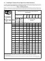
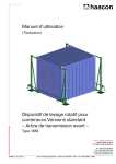
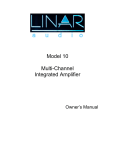
004 859C
Paralleling Arc
Welding Power
Sources
Visit our website at
www.MillerWelds.com
2014−09
SECTION 1 − SAFETY PRECAUTIONS - READ BEFORE USING
som 2013−09
7
Protect yourself and others from injury — read, follow, and save these important safety precautions and operating instructions.
1-1. Symbol Usage
DANGER! − Indicates a hazardous situation which, if
not avoided, will result in death or serious injury. The
possible hazards are shown in the adjoining symbols
or explained in the text.
Indicates a hazardous situation which, if not avoided,
could result in death or serious injury. The possible
hazards are shown in the adjoining symbols or explained in the text.
NOTICE − Indicates statements not related to personal injury.
. Indicates special instructions.
This group of symbols means Warning! Watch Out! ELECTRIC
SHOCK, MOVING PARTS, and HOT PARTS hazards. Consult symbols and related instructions below for necessary actions to avoid the
hazards.
1-2. Arc Welding Hazards
The symbols shown below are used throughout this manual
to call attention to and identify possible hazards. When you
see the symbol, watch out, and follow the related instructions
to avoid the hazard. The safety information given below is
only a summary of the more complete safety information
found in the Safety Standards listed in Section 1-5. Read and
follow all Safety Standards.
Only qualified persons should install, operate, maintain, and
repair this unit.
During operation, keep everybody, especially children, away.
ELECTRIC SHOCK can kill.
Touching live electrical parts can cause fatal shocks
or severe burns. The electrode and work circuit is
electrically live whenever the output is on. The input
power circuit and machine internal circuits are also
live when power is on. In semiautomatic or automatic
wire welding, the wire, wire reel, drive roll housing,
and all metal parts touching the welding wire are
electrically live. Incorrectly installed or improperly
grounded equipment is a hazard.
D Do not touch live electrical parts.
D Wear dry, hole-free insulating gloves and body protection.
D Insulate yourself from work and ground using dry insulating mats
or covers big enough to prevent any physical contact with the work
or ground.
D Do not use AC output in damp areas, if movement is confined, or if
there is a danger of falling.
D Use AC output ONLY if required for the welding process.
D If AC output is required, use remote output control if present on
unit.
D Additional safety precautions are required when any of the following electrically hazardous conditions are present: in damp
locations or while wearing wet clothing; on metal structures such
as floors, gratings, or scaffolds; when in cramped positions such
as sitting, kneeling, or lying; or when there is a high risk of unavoidable or accidental contact with the workpiece or ground. For these
conditions, use the following equipment in order presented: 1) a
semiautomatic DC constant voltage (wire) welder, 2) a DC manual
(stick) welder, or 3) an AC welder with reduced open-circuit voltage. In most situations, use of a DC, constant voltage wire welder
is recommended. And, do not work alone!
D Disconnect input power or stop engine before installing or
servicing this equipment. Lockout/tagout input power according to
OSHA 29 CFR 1910.147 (see Safety Standards).
D Properly install, ground, and operate this equipment according to
its Owner’s Manual and national, state, and local codes.
D Always verify the supply ground − check and be sure that input
power cord ground wire is properly connected to ground terminal in
D
D
D
D
D
D
D
D
D
D
D
D
D
D
D
D
disconnect box or that cord plug is connected to a properly
grounded receptacle outlet.
When making input connections, attach proper grounding conductor first − double-check connections.
Keep cords dry, free of oil and grease, and protected from hot metal
and sparks.
Frequently inspect input power cord and ground conductor for
damage or bare wiring – replace immediately if damaged – bare
wiring can kill.
Turn off all equipment when not in use.
Do not use worn, damaged, undersized, or repaired cables.
Do not drape cables over your body.
If earth grounding of the workpiece is required, ground it directly
with a separate cable.
Do not touch electrode if you are in contact with the work, ground,
or another electrode from a different machine.
Do not touch electrode holders connected to two welding machines at the same time since double open-circuit voltage will be
present.
Use only well-maintained equipment. Repair or replace damaged
parts at once. Maintain unit according to manual.
Wear a safety harness if working above floor level.
Keep all panels and covers securely in place.
Clamp work cable with good metal-to-metal contact to workpiece
or worktable as near the weld as practical.
Insulate work clamp when not connected to workpiece to prevent
contact with any metal object.
Do not connect more than one electrode or work cable to any
single weld output terminal. Disconnect cable for process not in
use.
Use GFCI protection when operating auxiliary equipment in damp
or wet locations.
SIGNIFICANT DC VOLTAGE exists in inverter welding power sources AFTER removal of input power.
D Turn Off inverter, disconnect input power, and discharge input
capacitors according to instructions in Maintenance Section
before touching any parts.
HOT PARTS can burn.
D Do not touch hot parts bare handed.
D Allow cooling period before working on equipment.
D To handle hot parts, use proper tools and/or
wear heavy, insulated welding gloves and
clothing to prevent burns.
004 859 Page 1
FUMES AND GASES can be hazardous.
Welding produces fumes and gases. Breathing
these fumes and gases can be hazardous to your
health.
D Keep your head out of the fumes. Do not breathe the fumes.
D If inside, ventilate the area and/or use local forced ventilation at the
arc to remove welding fumes and gases. The recommended way
to determine adequate ventilation is to sample for the composition
and quantity of fumes and gases to which personnel are exposed.
D If ventilation is poor, wear an approved air-supplied respirator.
D Read and understand the Safety Data Sheets (SDSs) and the
manufacturer’s instructions for adhesives, coatings, cleaners,
consumables, coolants, degreasers, fluxes, and metals.
D Work in a confined space only if it is well ventilated, or while
wearing an air-supplied respirator. Always have a trained watchperson nearby. Welding fumes and gases can displace air and
lower the oxygen level causing injury or death. Be sure the breathing air is safe.
D Do not weld in locations near degreasing, cleaning, or spraying operations. The heat and rays of the arc can react with vapors to form
highly toxic and irritating gases.
D Do not weld on coated metals, such as galvanized, lead, or
cadmium plated steel, unless the coating is removed from the weld
area, the area is well ventilated, and while wearing an air-supplied
respirator. The coatings and any metals containing these elements
can give off toxic fumes if welded.
ARC RAYS can burn eyes and skin.
Arc rays from the welding process produce intense
visible and invisible (ultraviolet and infrared) rays
that can burn eyes and skin. Sparks fly off from the
weld.
D Wear an approved welding helmet fitted with a proper shade of
filter lenses to protect your face and eyes from arc rays and
sparks when welding or watching (see ANSI Z49.1 and Z87.1
listed in Safety Standards).
D Wear approved safety glasses with side shields under your
helmet.
D Use protective screens or barriers to protect others from flash,
glare and sparks; warn others not to watch the arc.
D Wear body protection made from durable, flame−resistant material (leather, heavy cotton, wool). Body protection includes
oil-free clothing such as leather gloves, heavy shirt, cuffless
trousers, high shoes, and a cap.
WELDING can cause fire or explosion.
Welding on closed containers, such as tanks,
drums, or pipes, can cause them to blow up. Sparks
can fly off from the welding arc. The flying sparks, hot
workpiece, and hot equipment can cause fires and
burns. Accidental contact of electrode to metal objects can cause
sparks, explosion, overheating, or fire. Check and be sure the area is
safe before doing any welding.
D Remove all flammables within 35 ft (10.7 m) of the welding arc. If
this is not possible, tightly cover them with approved covers.
D Do not weld where flying sparks can strike flammable material.
D Protect yourself and others from flying sparks and hot metal.
D Be alert that welding sparks and hot materials from welding can
easily go through small cracks and openings to adjacent areas.
D Watch for fire, and keep a fire extinguisher nearby.
D Be aware that welding on a ceiling, floor, bulkhead, or partition can
cause fire on the hidden side.
D Do not weld on containers that have held combustibles, or on
closed containers such as tanks, drums, or pipes unless they are
properly prepared according to AWS F4.1 and AWS A6.0 (see
Safety Standards).
D Do not weld where the atmosphere may contain flammable dust,
gas, or liquid vapors (such as gasoline).
D Connect work cable to the work as close to the welding area as
practical to prevent welding current from traveling long, possibly
unknown paths and causing electric shock, sparks, and fire
hazards.
D Do not use welder to thaw frozen pipes.
004 859 Page 2
D Remove stick electrode from holder or cut off welding wire at
contact tip when not in use.
D Wear body protection made from durable, flame−resistant material
(leather, heavy cotton, wool). Body protection includes oil-free
clothing such as leather gloves, heavy shirt, cuffless trousers, high
shoes, and a cap.
D Remove any combustibles, such as a butane lighter or matches,
from your person before doing any welding.
D After completion of work, inspect area to ensure it is free of sparks,
glowing embers, and flames.
D Use only correct fuses or circuit breakers. Do not oversize or bypass them.
D Follow requirements in OSHA 1910.252 (a) (2) (iv) and NFPA 51B
for hot work and have a fire watcher and extinguisher nearby.
D Read and understand the Safety Data Sheets (SDSs) and the
manufacturer’s instructions for adhesives, coatings, cleaners,
consumables, coolants, degreasers, fluxes, and metals.
FLYING METAL or DIRT can injure eyes.
D Welding, chipping, wire brushing, and grinding
cause sparks and flying metal. As welds cool,
they can throw off slag.
D Wear approved safety glasses with side
shields even under your welding helmet.
BUILDUP OF GAS can injure or kill.
D Shut off compressed gas supply when not in use.
D Always ventilate confined spaces or use
approved air-supplied respirator.
ELECTRIC AND MAGNETIC FIELDS (EMF)
can affect Implanted Medical Devices.
D Wearers of Pacemakers and other Implanted
Medical Devices should keep away.
D Implanted Medical Device wearers should consult their doctor
and the device manufacturer before going near arc welding, spot
welding, gouging, plasma arc cutting, or induction heating
operations.
NOISE can damage hearing.
Noise from some processes or equipment can
damage hearing.
D Wear approved ear protection if noise level is high.
CYLINDERS can explode if damaged.
Compressed gas cylinders contain gas under high
pressure. If damaged, a cylinder can explode. Since
gas cylinders are normally part of the welding
process, be sure to treat them carefully.
D Protect compressed gas cylinders from excessive heat, mechanical shocks, physical damage, slag, open flames, sparks, and arcs.
D Install cylinders in an upright position by securing to a stationary
support or cylinder rack to prevent falling or tipping.
D Keep cylinders away from any welding or other electrical circuits.
D Never drape a welding torch over a gas cylinder.
D Never allow a welding electrode to touch any cylinder.
D Never weld on a pressurized cylinder − explosion will result.
D Use only correct compressed gas cylinders, regulators, hoses,
and fittings designed for the specific application; maintain them
and associated parts in good condition.
D Turn face away from valve outlet when opening cylinder valve. Do
not stand in front of or behind the regulator when opening the valve.
D Keep protective cap in place over valve except when cylinder is in
use or connected for use.
D Use the right equipment, correct procedures, and sufficient number of persons to lift and move cylinders.
D Read and follow instructions on compressed gas cylinders,
associated equipment, and Compressed Gas Association (CGA)
publication P-1 listed in Safety Standards.
1-3. Additional Symbols For Installation, Operation, And Maintenance
FIRE OR EXPLOSION hazard.
D Do not install or place unit on, over, or near
combustible surfaces.
D Do not install unit near flammables.
D Do not overload building wiring − be sure power supply system is
properly sized, rated, and protected to handle this unit.
FALLING EQUIPMENT can injure.
D Use lifting eye to lift unit only, NOT running
gear, gas cylinders, or any other accessories.
D Use equipment of adequate capacity to lift and
support unit.
D If using lift forks to move unit, be sure forks are long enough to
extend beyond opposite side of unit.
D Keep equipment (cables and cords) away from moving vehicles
when working from an aerial location.
D Follow the guidelines in the Applications Manual for the Revised
NIOSH Lifting Equation (Publication No. 94−110) when manually lifting heavy parts or equipment.
OVERUSE can cause OVERHEATING
MOVING PARTS can injure.
D Keep away from moving parts such as fans.
D Keep all doors, panels, covers, and guards
closed and securely in place.
D Have only qualified persons remove doors, panels, covers, or
guards for maintenance and troubleshooting as necessary.
D Reinstall doors, panels, covers, or guards when maintenance is
finished and before reconnecting input power.
READ INSTRUCTIONS.
D Read and follow all labels and the Owner’s
Manual carefully before installing, operating, or
servicing unit. Read the safety information at
the beginning of the manual and in each
section.
D Use only genuine replacement parts from the manufacturer.
D Perform maintenance and service according to the Owner’s
Manuals, industry standards, and national, state, and local
codes.
D Allow cooling period; follow rated duty cycle.
D Reduce current or reduce duty cycle before
starting to weld again.
D Do not block or filter airflow to unit.
H.F. RADIATION can cause interference.
FLYING SPARKS can injure.
D Wear a face shield to protect eyes and face.
D Shape tungsten electrode only on grinder with
proper guards in a safe location wearing proper
face, hand, and body protection.
D
D Sparks can cause fires — keep flammables away.
D
STATIC (ESD) can damage PC boards.
D Put on grounded wrist strap BEFORE handling
boards or parts.
D Use proper static-proof bags and boxes to
store, move, or ship PC boards.
D
D
D High-frequency (H.F.) can interfere with radio
navigation, safety services, computers, and
communications equipment.
D Have only qualified persons familiar with
electronic equipment perform this installation.
The user is responsible for having a qualified electrician promptly correct any interference problem resulting from the installation.
If notified by the FCC about interference, stop using the
equipment at once.
Have the installation regularly checked and maintained.
Keep high-frequency source doors and panels tightly shut, keep
spark gaps at correct setting, and use grounding and shielding to
minimize the possibility of interference.
MOVING PARTS can injure.
ARC WELDING can cause interference.
D Keep away from moving parts.
D Keep away from pinch points such as drive
rolls.
WELDING WIRE can injure.
D Do not press gun trigger until instructed to do
so.
D Do not point gun toward any part of the body,
other people, or any metal when threading
welding wire.
BATTERY EXPLOSION can injure.
D Do not use welder to charge batteries or jump
start vehicles unless it has a battery charging
feature designed for this purpose.
D
D
D
D
D Electromagnetic energy can interfere with
sensitive electronic equipment such as
computers and computer-driven equipment
such as robots.
D Be sure all equipment in the welding area is
electromagnetically compatible.
To reduce possible interference, keep weld cables as short as
possible, close together, and down low, such as on the floor.
Locate welding operation 100 meters from any sensitive electronic equipment.
Be sure this welding machine is installed and grounded
according to this manual.
If interference still occurs, the user must take extra measures
such as moving the welding machine, using shielded cables,
using line filters, or shielding the work area.
004 859 Page 3
1-4. California Proposition 65 Warnings
Welding or cutting equipment produces fumes or gases
which contain chemicals known to the State of California to
cause birth defects and, in some cases, cancer. (California
Health & Safety Code Section 25249.5 et seq.)
This product contains chemicals, including lead, known to
the state of California to cause cancer, birth defects, or other
reproductive harm. Wash hands after use.
1-5. Principal Safety Standards
Safety in Welding, Cutting, and Allied Processes, ANSI Standard Z49.1,
is available as a free download from the American Welding Society at
http://www.aws.org or purchased from Global Engineering Documents
(phone: 1-877-413-5184, website: www.global.ihs.com).
Safe Practices for the Preparation of Containers and Piping for Welding
and Cutting, American Welding Society Standard AWS F4.1, from Global Engineering Documents (phone: 1-877-413-5184, website:
www.global.ihs.com).
Safe Practices for Welding and Cutting Containers that have Held Combustibles, American Welding Society Standard AWS A6.0, from Global
Engineering Documents (phone: 1-877-413-5184,
website: www.global.ihs.com).
National Electrical Code, NFPA Standard 70, from National Fire Protection Association, Quincy, MA 02269 (phone: 1-800-344-3555, website:
www.nfpa.org and www. sparky.org).
Safe Handling of Compressed Gases in Cylinders, CGA Pamphlet P-1,
from Compressed Gas Association, 14501 George Carter Way, Suite
103, Chantilly, VA 20151 (phone: 703-788-2700, website:www.cganet.com).
Safety in Welding, Cutting, and Allied Processes, CSA Standard
W117.2, from Canadian Standards Association, Standards Sales, 5060
Spectrum Way, Suite 100, Ontario, Canada L4W 5NS (phone:
800-463-6727, website: www.csa-international.org).
Safe Practice For Occupational And Educational Eye And Face Protection, ANSI Standard Z87.1, from American National Standards Institute,
25 West 43rd Street, New York, NY 10036 (phone: 212-642-4900, website: www.ansi.org).
Standard for Fire Prevention During Welding, Cutting, and Other Hot
Work, NFPA Standard 51B, from National Fire Protection Association,
Quincy, MA 02269 (phone: 1-800-344-3555, website: www.nfpa.org.
OSHA, Occupational Safety and Health Standards for General Industry, Title 29, Code of Federal Regulations (CFR), Part 1910, Subpart Q,
and Part 1926, Subpart J, from U.S. Government Printing Office, Superintendent of Documents, P.O. Box 371954, Pittsburgh, PA 15250-7954
(phone: 1-866-512-1800) (there are 10 OSHA Regional Offices—
phone for Region 5, Chicago, is 312-353-2220, website:
www.osha.gov).
Applications Manual for the Revised NIOSH Lifting Equation, The National Institute for Occupational Safety and Health (NIOSH), 1600
Clifton Rd, Atlanta, GA 30333 (phone: 1-800-232-4636, website:
www.cdc.gov/NIOSH).
1-6. EMF Information
Electric current flowing through any conductor causes localized electric
and magnetic fields (EMF). The current from arc welding (and allied processes including spot welding, gouging, plasma arc cutting, and
induction heating operations) creates an EMF field around the welding
circuit. EMF fields may interfere with some medical implants, e.g. pacemakers. Protective measures for persons wearing medical implants
have to be taken. For example, restrict access for passers−by or conduct individual risk assessment for welders. All welders should use the
following procedures in order to minimize exposure to EMF fields from
the welding circuit:
1. Keep cables close together by twisting or taping them, or using a
cable cover.
2. Do not place your body between welding cables. Arrange cables
to one side and away from the operator.
3. Do not coil or drape cables around your body.
004 859 Page 4
4. Keep head and trunk as far away from the equipment in the
welding circuit as possible.
5. Connect work clamp to workpiece as close to the weld as
possible.
6. Do not work next to, sit or lean on the welding power source.
7. Do not weld whilst carrying the welding power source or wire
feeder.
About Implanted Medical Devices:
Implanted Medical Device wearers should consult their doctor and the
device manufacturer before performing or going near arc welding, spot
welding, gouging, plasma arc cutting, or induction heating operations.
If cleared by your doctor, then following the above procedures is recommended.
SECTION 2 − PARALLELING
NOTICE − These procedures should only be used to parallel welding power sources manufactured by Miller Electric Mfg.
. The welding power source Owner’s Manual may provide additional information on how to connect units in parallel.
2-1. Typical Uses For Paralleled Welding Power Sources
When amperage demands for a particular application exceed the capabilities of one welding power source, two or more electrically similar welding
power sources may be connected in parallel to provide the amperage required.
When paralleled correctly, the amperage of the paralleled welding power sources is the sum of the amperage supplied by each power source. Voltage
remains the same as for one welding power source.
Compatible inverter DC welding power sources or engine driven welder/generators, or transformer-type welding power sources can be paralleled.
Each type requires special attention to certain areas unique to the equipment involved. The safety and efficiency of a paralleled system depends upon
careful attention to correct paralleling procedures.
. It may be advantageous to use a single welding power source capable of providing the required amperage rather than connecting units in parallel.
. The weld output of two power sources connected in parallel may be less than the total weld output of the individual power sources. Contact Miller
Electric Mfg. if you do not understand these procedures.
2-2.
Equipment
The following equipment can be successfully paralleled:
D
D
D
D
DC Constant Current (CC) Rectifier-Type Power Sources
DC Constant Current (CC) Inverter-Type Power Sources
DC Constant Current (CC) Rectifier Engine-Driven Welder/Generators
AC Constant Current (CC) Transformer-Type Power Sources
The following equipment is not recommended for paralleling:
D
D
D
D
D
Most DC Constant Voltage (CV) Power Sources
Brush Commutator Design Engine Driven Welder/Generators
Motor Generator DC Power Sources
AC Engine Driven Welder/Generators
AC Inverter-Type Power Sources
SECTION 3 − RECOMMENDED EQUIPMENT
3-1.
Paralleling DC Constant Current Power Sources
Two or more DC transformer/rectifier or inverter power sources can be paralleled as follows:
1.
Each power source to be paralleled must be individually protected (fused). For transformer/rectifier units, all must be connected to the same primary input power feed and be connected the same phase to phase.
2.
Power sources must all be connected for the same polarity. If the power sources are equipped with polarity switches, they must all be set for the
same polarity.
3.
4.
Make sure each power source to be paralleled is in constant current (CC) mode.
If the power source has various output terminals such as High and Low (range), use the same range terminal on all power sources connected in
parallel.
If the power sources are equipped with a range switch, the range switch on all paralleled power sources should be in the same range.
5.
Amperage adjustment controls on all power sources should be adjusted to provide the same output. Do not split the load unevenly. For example, if
800 amps are required from a paralleled connection of two power sources, adjust amperage control of each power source to provide 400 amps.
6.
The amperage being used and total length of cable must be considered when selecting cable sizes. Use Table 3-1 to select weld cable size. Use
Figure 1-1 to compute weld cable size.
004 859 Page 5
3-2.
Paralleling DC Constant Current Engine Driven Welder/Generators
DC constant current engine-driven welder/generators can be paralleled like the transformer/rectifier and inverter-type power sources. If the unit is an
AC/DC unit, using the DC output for paralleling is required. The rectifier permits current flow in only one direction so a feedback situation does not occur
even if the outputs are not exactly balanced. See Section 3-1 for paralleling instructions.
Table 3-1. Selecting Cable Sizes*
NOTICE − The Total Cable Length in Weld Circuit (see table below) is the combined length of both weld cables. For example, if the power source is
100 ft (30 m) from the workpiece, the total cable length in the weld circuit is 200 ft (2 cables x 100 ft). Use the 200 ft (60 m) column to determine cable
size.
Weld Cable Size** and Total Cable (Copper) Length in Weld Circuit
Not Exceeding***
Weld Output
Terminals
!
Turn off power before connecting to
weld output terminals.
!
Do not use worn,
damaged,
undersized, or repaired
cables.
* This
100 ft (30 m) or Less
150 ft
(45 m)
200 ft
(60 m)
250 ft
(70 m)
300 ft
(90 m)
350 ft
400 ft
(105 m) (120 m)
10 − 60%
Duty
Cycle
60 − 100%
Duty
Cycle
AWG (mm2)
AWG (mm2)
100
4 (20)
4 (20)
4 (20)
3 (30)
2 (35)
1 (50)
1/0 (60)
1/0 (60)
150
3 (30)
3 (30)
2 (35)
1 (50)
1/0 (60)
2/0 (70)
3/0 (95)
3/0 (95)
200
3 (30)
2 (35)
1 (50)
1/0 (60)
2/0 (70)
3/0 (95)
4/0 (120)
4/0 (120)
250
2 (35)
1 (50)
1/0 (60)
2/0 (70)
3/0 (95)
4/0 (120)
2x2/0
(2x70)
2x2/0
(2x70)
300
1 (50)
1/0 (60)
2/0 (70)
3/0 (95)
4/0 (120)
2x2/0
(2x70)
2x3/0
(2x95)
2x3/0
(2x95)
350
1/0 (60)
2/0 (70)
3/0 (95)
4/0 (120)
2x2/0
(2x70)
2x3/0
(2x95)
2x3/0
(2x95)
2x4/0
(2x120)
400
1/0 (60)
2/0 (70)
3/0 (95)
4/0 (120)
2x2/0
(2x70)
2x3/0
(2x95)
2x4/0
(2x120)
2x4/0
(2x120)
500
2/0 (70)
3/0 (95)
4/0 (120)
2x2/0
(2x70)
2x3/0
(2x95)
2x4/0
(2x120)
3x3/0
(3x95)
3x3/0
(3x95)
600
3/0 (95)
4/0 (120)
2x2/0
(2x70)
2x3/0
(2x95)
2x4/0
(2x120)
3x3/0
(3x95)
3x4/0
(3x120)
3x4/0
(3x120)
700
4/0 (120)
2x2/0 (2x70)
2x3/0
(2x95)
2x4/0
(2x120)
3x3/0
(3x95)
3x4/0
(3x120)
3x4/0
(3x120)
4x4/0
(4x120)
800
4/0 (120)
2x2/0 (2x70)
2x3/0
(2x95)
2x4/0
(2x120)
3x4/0
(3x120)
3x4/0
(3x120)
4x4/0
(4x120)
4x4/0
(4x120)
900
2x2/0 (2x70)
2x3/0 (2x95)
2x4/0
(2x120)
3x3/0
(3x95)
1000
2x2/0 (2x70)
2x3/0 (2x95)
2x4/0
(2x120)
3x3/0
(3x95)
1250
2x3/0 (2x95)
2x4/0
(2x120)
3x3/0
(3x95)
4x3/0
(4x95)
1500
600 (300)
750 (400)
1000 (500)
2x750
(2x400)
1750
750 (400)
1000 (500)
2x750
(2x400)
2x1000
(2x500)
2000
800 (400)
1000 (500)
2x750
(2x400)
2x1000
(2x500)
Welding
Amperes
10 − 100% Duty Cycle
AWG (mm2)
chart is a general guideline and may not suit all applications. If cable overheats, use next size larger cable.
**Weld cable size (AWG) is based on either a 4 volts or less drop or a current density of at least 300 circular mils per ampere.
( ) = mm2 for metric use
***For distances longer than those shown in this guide, call a factory applications rep. at 920-735-4505 (Miller) or 1-800-332-3281 (Hobart).
Ref. S-0007-K 2013−09
004 859 Page 6
MAXIMUM CABLE
CAPACITY BASED
ON TEMPERATURE RISE
CABLE AMPS
8
60
6
90
4
120
2
240
1
300
1/0
360
2/0
450
3/0
540
640
4/0
710
(2) 2/0
780
(2) 3/0
860
(2) 4/0
940
(2) 4/0
1090
(3) 3/0
1220
(3) 4/0
1340
(4) 4/0
1450
(4) 4/0
900 MCM 1540
1000 MCM 1630
Reference Line
AMPERES
2000
VOLTS
LOSS
IN
CABLES
25
1500
TOTAL LENGTH
OF CABLES
IN FEET
20
1000
30
40
50
900
800
700
100
600
200
500
300
400
500
600
400
800
300
1000
1200
1400
1600
1800
2000
250
CABLE
SIZE
AWG
8
7
6
5
4
3
2
1
1/0
2/0
3/0
4/0
(2) 2/0
(2) 3/0
(2) 4/0
(3) 3/0
(3) 4/0
(4) 4/0
1000 MCM
FOR AC USE NEXT
LARGER CABLE SIZE
20
15
10
9
8
7
6
5
4
3.5
3
RECOMMENDED
LOSS ALLOWED
4 VOLTS OR LESS
2.5
2
1.5
200
150
100
Figure 3-1. Nomogram For Computing Weld Cable Size
3-3.
Using the Nomogram
A. Example 1
The welding current will be 200 amperes DC. The work lead is 190 feet long while the electrode lead is 210 feet long. The total lead length is 400 feet.
Draw a straight line from 200 amperes through 400 feet and intersect the reference line. Draw a straight line from the reference intersection through and
cable size that will give less than a 4 volt loss. In this example, a 4/0 cable will give a 3.9 volt loss. Check this cable size in the maximum current capacity
table. It shows a 4/0 cable has a maximum capacity of 640 amperes, well above the 200 amperes used in this example.
The solution: Use 4/0 weld cable for the connections.
004 859 Page 7
B. Example 2
The welding current will be 400 amperes DC. The total lead length is 400 feet. The weld cable available is 4/0.
Draw a straight line from 400 amperes through 400 feet and intersect the reference line. Draw a straight line from the reference intersection through 4/0
cable. The result is a 7.8 volt loss which is above the 4 volt loss recommended.
The solution: Use two 4/0 cables in parallel for the work lead and electrode lead. The 7.8 volt loss can be halved by doubling up the cables. This gives a
3.9 volt loss because each cable is carrying 200 amperes.
C. Example 3
A construction company uses electrode holders with a 30 foot whip of 2/0 cable as standard equipment. The largest electrode used requires 400 amperes DC maximum. For standardization, all leads are cut to 50 foot lengths. What size cable should be used for these 50 foot lengths to keep voltage
loss below the recommend 4 volts.
Draw a straight line from 400 amperes through 30 feet and intersect the reference line. Draw a line from the reference intersection through 2/0 cable.
The result is a 1 volt loss. The 30 foot whip of 2/0 cable is sufficient to handle 400 amperes.
Draw a straight line from 400 amperes through 100 feet (50 foot work lead and 50 foot electrode lead) and intersect the reference line. Draw a straight
line from the reference intersection through 3/0 cable (the smallest cable size capable of handling 400 ±100 amperes). The result is a 3 volt loss.
The solution: The 50 foot leads should be 3/0 cable to handle 400 amperes with a 3 volt loss. If the work is further than 50 feet from the machine,
recalculate. It may be necessary to use several paralleled cables to handle the output.
Notes
004 859 Page 8
Notes
004 859 Page 9
3-4.
Connecting Cables
2
1
5
7
6
5
6
7
3
5
6
7
004 859 Page 10
1
Tools Needed:
2
3
4
5
Transformer/Rectifier Welding
Power Source
Inverter Welding Power
Source
Engine-Driven
Welder/Generator
AC/DC Transformer/Rectifier
Welding Power Source
Weld Cable
Connect separate cables of adequate size and equal length to the
weld output terminals.
6
Junction
Where the weld cables are joined,
be sure connecting hardware is adequate for expected amperage and
that the junction is properly insulated.
7
Single Weld Cable
The single cable must be adequate
to carry the full expected amperage.
4
5
6
7
801 701-A / Ref: 804 257-A / Ref: 804 259-A / Ref: 804 328-A
004 859 Page 11
3-5.
Paralleling AC Constant Current Transformer-Type Power Sources
AC transformer-type power sources can be paralleled for increased amperage demands; however, additional precautions must be taken.
The following procedure is recommended:
1.
Connect primary wiring of suitable size from each power source to the same phase in the main disconnect switch box. This arrangement enables
all power sources to be connected to the power lines simultaneously when the line disconnect switch is placed in the “On” position.
All primary connections should be made by a qualified electrician. Wire and fuse sizes must be in accordance with National Electrical Code specifications and local code requirements.
When connecting two or more power sources in parallel, the primary side of each power source must be individually protected (fused).
Primary wiring from the primary terminals to the common switch should be the same length and size. It is desirable that the junction of the primary
wiring be made at the line disconnect rather than at the power source terminal board.
2.
Make sure all power sources connected in parallel have the proper phase relationship. Check this as follows:
a.
b.
c.
Temporarily connect all electrode terminals together with a No. 14 AWG or larger wire.
Energize all power sources.
With a voltmeter, check the voltage across the work terminal of one power source and the work terminal of the other power source(s). If the
voltage is approximately zero, the phase relationship is correct. If, however, the voltage is substantially greater than zero and slightly less
than two times the individual machine open−circuit voltage, the phase relationship is incorrect. Reverse the primary connections on one
power source at a time until zero volts between all work terminals is achieved. Remove the temporary jumper wires connecting the electrode
terminals.
3.
When making secondary cable connections, the same procedure and recommendations outlined for DC constant current transformer/rectifier
power sources should be used. Be sure connections are made work to work and electrode to electrode.
4.
When using AC, power source control systems must be synchronized according to the instructions provided in the power source Owner’s Manual.
3-6.
Paralleling AC/DC Constant Voltage/Constant Current Transformer/Rectifier Type
Power Sources
When connecting two or more units in parallel, do not use more than one unit in CV mode. If constant voltage output is required, operate only one unit in
the CV mode and put the remaining units in the CC mode with their output set to a percentage of total welding output divided by the total number of units
used. When using AC, be sure the input power phase relationship is correct according to Section 3-5 and that power sources control systems are
synchronized according to their instructions.
004 859 Page 12
SECTION 4 − OTHER EQUIPMENT
4-1.
Paralleling DC Constant Voltage Power Sources (Not Recommended)
It is very difficult to balance these machines as they will only balance in a very narrow band of operation; therefore, paralleling is not typically recommended.
4-2.
Paralleling Brush Commutator Design Engine Driven Welder/Generators Or Motor
Generators (Not Recommended)
The amperage output of these machines must be exactly balanced, otherwise, one power source tries to drive the other. Paralleling brush commutator
design machines is not recommended for this reason. If the outputs are not exactly balanced, the power source supplying the higher output feeds
current back to the other power source. The current goes through the paralleled connection, through the brushes to the commutator and is dissipated as
heat in the windings. The heat build−up can cause failure of the generator components.
4-3.
Paralleling AC Engine Driven Welder/Generators (Not Recommended)
Any fluctuation of engine speed will affect output amperage and frequency resulting in a feedback situation. Paralleling AC engine driven power sources
is not recommended for this reason. If the engine speed fluctuates, the control systems of the power sources do not have synchronization capabilities to
compensate for this fluctuation. The AC output is no longer in phase which can be a hazard for hand−held welding operations. The current feedback
from one power source to the other would cause heat build up in the windings. The heat build−up can cause failure of generator components.
4-4.
Paralleling AC Inverter Type Power Sources (Not Recommended)
The control systems of AC inverter power sources do not allow for synchronization of the output when the outputs are not exactly balanced. If the AC
output is not in phase it can be a hazard for hand−held welding operations. The current feedback from one power source to the other would cause heat
build up in the equipment. The heat build−up can cause failure of power source components.
004 859 Page 13
Owner’s Record
Please complete and retain with your personal records.
Model Name
Serial/Style Number
Purchase Date
(Date which equipment was delivered to original customer.)
Distributor
Address
City
State
Zip
For Service
Contact a DISTRIBUTOR or SERVICE AGENCY near you.
Always provide Model Name and Serial/Style Number.
Contact your Distributor for:
Welding Supplies and Consumables
Options and Accessories
Personal Safety Equipment
Service and Repair
Miller Electric Mfg. Co.
An Illinois Tool Works Company
1635 West Spencer Street
Appleton, WI 54914 USA
Replacement Parts
Training (Schools, Videos, Books)
Technical Manuals (Servicing Information
and Parts)
Circuit Diagrams
For International Locations Visit
www.MillerWelds.com
Welding Process Handbooks
To locate a Distributor or Service Agency visit
www.millerwelds.com or call 1-800-4-A-Miller
Contact the Delivering Carrier to:
File a claim for loss or damage during
shipment.
For assistance in filing or settling claims, contact
your distributor and/or equipment manufacturer’s
Transportation Department.
ORIGINAL INSTRUCTIONS − PRINTED IN USA
International Headquarters−USA
USA Phone: 920-735-4505 Auto-Attended
USA & Canada FAX: 920-735-4134
International FAX: 920-735-4125
© 2014 Miller Electric Mfg. Co.
2014−01