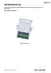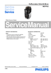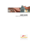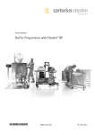
1
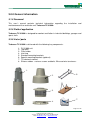
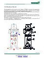
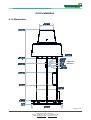
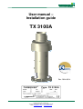
User manual –
Installation guide
TX 3100A
Rev. 2014.03.14
Page 1 of 18
Turbovex A/S
Industrivej 45, DK – 9600 Aars
Telefon: +45 96 98 14 62 – Fax: +45 98 96 42 24
e-mail: [email protected] – www.turbovex.dk
1.0.0 TABLE OF CONTENT
1.0.0 TABLE OF CONTENT................................................................................................2
3.0.0 GENEREL INFORMATION ........................................................................................3
3.1.0 FOREWORD ...............................................................................................................3
3.2.0 FIELD OF APPLICATION ................................................................................................3
3.3.0 LIST OF PARTS ...........................................................................................................3
3.4.0 FUNCTION OF THE UNIT ...............................................................................................4
4.0.0 INSTALLATION..........................................................................................................5
4.1.0 DIMENSIONS ..............................................................................................................5
4.2.0 PLACEMENT...............................................................................................................6
4.3. TEMPLATE ...................................................................................................................6
4.4.0 INSTALLING THE UNIT (STANDARD MOUNTING BRACKETS) ...............................................7
4.5.0 INSTALLING THE UNIT USING SPECIAL BRACKETS ...........................................................8
4.5.0 INSTALLING THE UNIT USING SPECIAL BRACKETS ...........................................................9
4.6.0 INSTALLING BOTTOM EXTENSION ................................................................................11
5.0.0 TECHNICAL SPECIFICATIONS ..............................................................................12
5.1.0 UNIT .......................................................................................................................12
6.0.0 ELECTRICAL INSTALLATION ................................................................................13
7.0.0 SERVICE ..................................................................................................................16
7.1.0 SERVICE REPORT .....................................................................................................16
7.2.0 FILTER CHANGE .......................................................................................................17
8.0.0 DECLARATION OF CONFORMITY.........................................................................18
Page 2 of 18
Turbovex A/S
Industrivej 45, DK – 9600 Aars
Telefon: +45 96 98 14 62 – Fax: +45 98 96 42 24
e-mail: [email protected] – www.turbovex.dk
3.0.0 Generel information
3.1.0 Foreword
This user´s manual contains technical information regarding the installation and
maintenance of the ventilation unit Turbovex TX 3100A.
3.2.0 Field of application
Turbovex TX 3100A is designed for comfort ventilation in industrial buildings, garages and
sports halls.
3.3.0 List of parts
Turbovex TX 3100A is delivered with the following key components.
1.
2.
3.
4.
5.
6.
7.
8.
TX 3100A unit
Top cone
Filter holder
Inlet ring
Standard mounting brackets
Special mounting brackets (optional)
TX electronic control
Silicone rubber + various screws and bolts. Wire and wire tensioners.
1.
2.
5.
6.
3.
4.
7.
Page 3 of 18
Turbovex A/S
Industrivej 45, DK – 9600 Aars
Telefon: +45 96 98 14 62 – Fax: +45 98 96 42 24
e-mail: [email protected] – www.turbovex.dk
3.4.0 Function of the unit
The principle of the heat recovery in the Turbovex TX3100A is based on the rotating heat
exchanger (B). The exhaust fan (A) extracts the warm room air from the funnel (D) though
half of the heat exchanger (B), and send it through the exhaust cap (F).
Simultaneously the inlet fan will (C) sucks air from the inlet cap (G) and send it through the
other half of the heat exchanger.
The heated fresh air is sent to (E), and diffused in the room.
One half of the rotating heat exchanger will heat up in the warm flow of the exhaust air.
When the heated material in the heat exchanger is in the cool flow of the inlet air, it will
deliver heat from the material to the fresh air.
The process is regenerative as the heat exchanger rotates at low rpm.
The heat exchanger is equipped with a cleaning sector creating a low pressure to
eliminate the possibility of undesirable leaks.
Page 4 of 18
Turbovex A/S
Industrivej 45, DK – 9600 Aars
Telefon: +45 96 98 14 62 – Fax: +45 98 96 42 24
e-mail: [email protected] – www.turbovex.dk
4.0.0 Installation
4.1.0 Dimensions
Adjust for
brackets
Page 5 of 18
Turbovex A/S
Industrivej 45, DK – 9600 Aars
Telefon: +45 96 98 14 62 – Fax: +45 98 96 42 24
e-mail: [email protected] – www.turbovex.dk
4.2.0 Placement
Turbovex TX 3100A is intended for installation through the roof. The unit can be placed in
roofs with inclines ranging from 0 to 45 degrees. Turbovex TX3100A is available with two
types of mounting brackets.
The standard mounting bracket places the inspection hatch inside the building.
The special mounting bracket is intended for use if you want the hatch placed outside the
building.
Standard bracket
Special bracket
4.3. Template
It is a good idea to create a template according to the
incline of the roof. Remember to mark 2 notches and
a center hole. The notches are for placing the unit
horizontally.
a 0 = Ø870 mm
a 5 = 870 x 880 mm
a 10 = 870 x 890 mm
a 15 = 870 x 900 mm
a 20 = 870 x 930 mm
a 25 = 870 x 970 mm
a 30 = 870 x 1010 mm
a 35 = 870 x 1070 mm
a 40 = 870 x 1140 mm
a 45 = 870 x 1240 mm
Page 6 of 18
Turbovex A/S
Industrivej 45, DK – 9600 Aars
Telefon: +45 96 98 14 62 – Fax: +45 98 96 42 24
e-mail: [email protected] – www.turbovex.dk
4.4.0 Installing the unit (standard mounting brackets)
Perform measurements and determine the placement
of the unit and drill a small center hole vertically
through the roof. Use the aforementioned template to
make the rest of the hole for the unit according to the
incline of the roof.
The mounting brackets are mounted between the
purlins at a distance of 1000 mm between the two
brackets. The mounting brackets are secured using
mounting screws top and bottom.
HexHead screw
Selftapping screw
The forks on the bracket are adjusted so they are
directly opposite and locked in place using selftapping screws through in the telescopic tubes.
The unit, weighing about 200 kg. is mounted in the
brackets so the studs fall into place in the saddle
brackets.
When installing on a slanted roof, please place the
unit so the service hatch is facing the ridge of the roof
to allow for easy access to the hatch.
Lifting studs
The unit can be lifted using the two lifting studs
mounted near the top of the unit.
Page 7 of 18
Turbovex A/S
Industrivej 45, DK – 9600 Aars
Telefon: +45 96 98 14 62 – Fax: +45 98 96 42 24
e-mail: [email protected] – www.turbovex.dk
Wire and wire tensioners are fitted in the four brackets
on the side of the unit. Tension is applied to the wires
between the supplied bracket mounted on purlins and
battens. The purpose of the wires is to adjust and
keep the unit in a vertical position.
The inlet ring is pushed onto the unit and secured
using self-tapping screws from both inside and
outside. Now proceed to complete the roofing.
The soft cover is pulled over the unit. Seal the edge
using silicone rubber. Use silicone rubber under the
vertical part of the cover and on the top of the edge to
secure a watertight joint.
Min 10 cm overlap
When the cover is cut, please note you will need a
10 cm overlap with the overlying roof tile or ridge.
The hole in the cover is cut using the same template
used for cutting the hole in the roof.
The hole in the cover must be cut in a diameter
about 5 cm smaller than that of the template to
ensure a tight fit.
The soft cover is fastened using self-tapping screws
and needs to be no more than 15 mm inside the unit
to ensure ample space for the rotating parts in the
unit.
Silicone
The filter holders are sealed with silicone rubber and
secured using self-tapping screws.
The top cone is screwed in place using M8 bolts.
Silicone grout
Page 8 of 18
Turbovex A/S
Industrivej 45, DK – 9600 Aars
Telefon: +45 96 98 14 62 – Fax: +45 98 96 42 24
e-mail: [email protected] – www.turbovex.dk
4.5.0 Installing the unit using special brackets
Template
Perform measurements and determine the placement
of the unit and drill a small center hole vertically
through the roof. The wooden frame is aligned with
the center hole. Now cut a square hole and secure
the frame to the rafters
Use a template (see 4.3.0 template) and cut a hole in
the wooden frame and the rest of the roof.
Apply Fast flash seal between the wooden frame and
the roof.
One part of the soft cover is mounted on the frame
and the hole is cut out.
The other cover is fastened so it covers the top of the
roof and goes min. 10 cm under the rooftop or the
next rooftile.
Min. 10 cm overlap
The two special brackets are mounted and the angle is adjusted according to the incline of
the roof. The rods are placed as shown on the figure so the saddles of the brackets are
nearer to the ventilation unit. The holes are placed in intervals of 5 degrees, from 0 to 45
degrees.
45 degrees
305 mm
0 degrees
700 mm
Page 9 of 18
Turbovex A/S
Industrivej 45, DK – 9600 Aars
Telefon: +45 96 98 14 62 – Fax: +45 98 96 42 24
e-mail: [email protected] – www.turbovex.dk
The unit, weighing about 200 kg is mounted in the
brackets so the studs fall into place in the saddle
brackets.
Place a bolt in the saddle brackets securing the studs
in place.
When installing the unit on a slant roof using special
brackets, ensure that the service hatch is faced away
from the ridge of the roof for better access.
Apply Fast Flash seal between the soft cover on the
wooden frame and the unit to make a watertight seal.
The large electric control unit can be moved to a
different location if needed.
The filter holders are sealed using silicone rubber seal
and secured in place using self-tapping screws.
The top cone is secured with M8 bolts. To place the
holes correct, make sure that the arrows on the
filterholder and the top cone are aligned.
Now you can mount the inlet ring or a bottom
extension. (see 4.6.0)
The intake ring is pushed over the two tubes in the
unit and secured with self-tapping screws from both
the inside and outside. Now finish the roofing.
Page 10 of 18
Turbovex A/S
Industrivej 45, DK – 9600 Aars
Telefon: +45 96 98 14 62 – Fax: +45 98 96 42 24
e-mail: [email protected] – www.turbovex.dk
4.6.0 Installing bottom extension
Dismantle the bottom filter and the 4 angle brackets
for the wires. The screws must remain in the unit so
the unit won´t be leaky.
4 pcs.
First mount the inner tube and then the outer tube on
the unit.
The intake ring is mounted on the extension tubes.
The filter and the angle brackets are reattached. The
brackets are fastened using the supplied screws in
the extension tubes.
Wire and wire tensioners are fitted. Tension is applied
to the wires between the supplied bracket mounted on
purlins and battens. The purpose of the wires is to
adjust and keep the unit steady in a vertical position.
Page 11 of 18
Turbovex A/S
Industrivej 45, DK – 9600 Aars
Telefon: +45 96 98 14 62 – Fax: +45 98 96 42 24
e-mail: [email protected] – www.turbovex.dk
5.0.0 Technical specifications
5.1.0 Unit
Type
: Turbovex TX 3100A
Capacity
: 1400 – 3000 m3/h
Forced operation
: 3400 m3/h
Power
: 1 x 230V / 50 Hz
Output (Motor)
: Max. 2x750 Watt
Energy consumption (3000 m3/h)
: 1044 W - 1,25 KJ/m3
Heat recovery (3000 m3/h)
: 75
%
Turbovex TX 3100A is tested in cooperation with Ziehl-abegg – www.ziehl-abegg.com
The airflow indicates the balanced air exchange in relation to the control voltage. (0-10
volt) and is shown in m³/h. The unit can be adjusted manually to suit your required air
exchange.
The sound level is shown in decibel – dB (A) in relation to air exchange.
The sound is measured in 1 to 5 meters from the unit under normal conditions.
Page 12 of 18
Turbovex A/S
Industrivej 45, DK – 9600 Aars
Telefon: +45 96 98 14 62 – Fax: +45 98 96 42 24
e-mail: [email protected] – www.turbovex.dk
6.0.0 Electrical installation
Page 13 of 18
Turbovex A/S
Industrivej 45, DK – 9600 Aars
Telefon: +45 96 98 14 62 – Fax: +45 98 96 42 24
e-mail: [email protected] – www.turbovex.dk
Page 14 of 18
Turbovex A/S
Industrivej 45, DK – 9600 Aars
Telefon: +45 96 98 14 62 – Fax: +45 98 96 42 24
e-mail: [email protected] – www.turbovex.dk
Page 15 of 18
Turbovex A/S
Industrivej 45, DK – 9600 Aars
Telefon: +45 96 98 14 62 – Fax: +45 98 96 42 24
e-mail: [email protected] – www.turbovex.dk
7.0.0 Service
7.1.0 Service report
Servicereport for model
Unit nr.
Installation address
Customer´s name
Road and number
Postcode and location
Telephone
Contact person
Phone number
Date
Status
Replacement of inlet filter
Replacement of exhaust filter
Cleaning of heat exchanger
Overall inside cleaning of unit
Damper exhaust motor
Hinges on the damper flap
Fan motor inlet
Fan motor exhaust
Rot. heat exchanger´s bearings
Rot. heat exchanger´s brushes
Rot. heat exchanger´s motor
Wires and penetrations
Temperature gauge
Control unit - motor
Motor mount / rubber mount
Pressure guard adjustment
Time set and date
CO2 sensor function
Pir sensor function
/
- 20
Not
applicable
Poor
Medium
Good
Replaced
Service Technician:
Turbovex A/S
Industrivej 45, DK – 9600 Aars
Telefon: +45 96 98 14 62 – Fax: +45 98 96 42 24
e-mail: [email protected] – www.turbovex.dk
Page 16 of 18
Turbovex A/S
Industrivej 45, DK – 9600 Aars
Telefon: +45 96 98 14 62 – Fax: +45 98 96 42 24
e-mail: [email protected] – www.turbovex.dk
7.2.0 Filter change
There is to filters in the TX 3100A there need to be
changed. The filters have to be changed about 2-4
times a year. Maintenance of the filters is necessary
or else you will damage the heat exchanger and the
unit will not work
The exhaust air filter is placed in the bottom of the
unit and is easy to remove and replace a new one.
The only ting there is holding the filter is a rubber on
the edge of the filter.
The rubber seal must be placed so the circular part is
facing outwards. Otherwise air leakage will occour
and there will be a fall hazard of the filter.
The supply air filter is placed at the outside under the
top cone, who’s projecting against wind and weather.
The filter stuck with Velcro and is therefore easy to
remove and replace a new one.
If you have some space problems when changing the
filter, it’s possible to remove the top cone.
Page 17 of 18
Turbovex A/S
Industrivej 45, DK – 9600 Aars
Telefon: +45 96 98 14 62 – Fax: +45 98 96 42 24
e-mail: [email protected] – www.turbovex.dk
8.0.0 Declaration of conformity
Page 18 of 18
Turbovex A/S
Industrivej 45, DK – 9600 Aars
Telefon: +45 96 98 14 62 – Fax: +45 98 96 42 24
e-mail: [email protected] – www.turbovex.dk