1
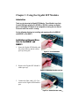
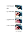
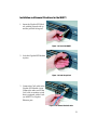
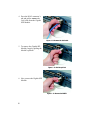
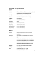
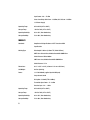
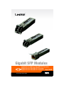
®
A Division of Cisco Systems, Inc.
Gigabit SFP Modules
WIRED
Gigabit Ethernet 1000 Base-T Mini-GBIC SFP Transceiver
Gigabit Ethernet SX Mini-GBIC SFP Transceiver
Gigabit Ethernet LH Mini-GBIC SFP Transceiver User Guide
Model No. MGBT1, MGBLH1, MGBSX1
Table of Contents
Chapter 1: Using the Gigabit SFP Modules
3
Introduction
3
Installation and Removal Directions for the MGBLH1 and MGBSX1 3
Installation and Removal Directions for the MGBT1
5
Appendix A: Specifications
Appendix B: Warranty Information
Appendix C: Regulatory Information
Appendix D: Contact Information
Gigabit SFP-UG-40210NC KL
2
7
9
10
13
Chapter 1: Using the Gigabit SFP Modules
Introduction
Thank you for choosing the Gigabit SFP Modules. These Modules insert into
the mini-GBIC ports on either the SR2024 or SR224G, creating new Gigabit
ports. Each Gigabit SFP Module is hot-swappable, meaning you can connect
them even when the switch is running.
Use the following directions for installing and removing either the MGBLH1
and MGBSX1 or the MGBT1.
Installation and Removal Directions for the MGBLH1 and
MGBSX1
1. Insert the Gigabit SFP Module with
the printed side up and the rubber
port cap facing out.
Figure 1-1: Insert the Module
2. Remove the Gigabit SFP Module’s
rubber port cap.
Figure 1-2: Removing the rubber port cap
3. Connect the fiber cable’s LC Connector to the Gigabit SFP Module’s
port.
Figure 1-3: Connect the fiber cable
3
4. Now the fiber is connected to the
Gigabit SFP Module and should be
functioning. Connect the other end
of the cable to an SFP Module to
verify that the fiber connection is
complete.
Figure 1-4: The connected fiber cable
5. Press the fiber cable’s connector
and pull to remove the fiber cable
from the Gigabit SFP Module.
Figure 1-5: Removing the fiber cable
6. To remove the Gigabit SFP Module,
begin by pulling the Module’s bail
latch.
Figure 1-6: Pull the bail latch
7. Now, remove the Gigabit SFP Module.
Figure 1-7: Remove the Module
4
Installation and Removal Directions for the MGBT1
1. Insert the Gigabit SFP Module with the printed side up
and the pull tab facing out.
Figure 1-8: Insert the MGBT1
2. Lock the Gigabit SFP Module
in place.
Figure 1-9: Lock the pull tab
3. Connect the Cat5 cable to the
Gigabit SFP Module’s port.
Connect the other end of the
Cat5 cable to another switch
that is equipped with a Linksys MGBT1 or Gigabit
Ethernet port.
Figure 1-10: Connect the Cat5 cable
5
4. Press the RJ-45 connector’s
tab and pull to remove the
Cat5 cable from the Gigabit
SFP Module.
Figure 1-11: Remove the Cat5 cable
5. To remove the Gigabit SFP
Module, begin by pulling the
Module’s pull tab.
Figure 1-12: Pull the pull tab
6. Now, remove the Gigabit SFP
Module.
Figure 1-13: Remove the MGBT1
6
Appendix A: Specifications
MGBT1
Standards:
IEEE 802.3z, IEEE 802.3u, IEEE 802.3ab compliant, Compliant with
Specifications of SFP Transceiver MSA Specification
Cabling Type:
UTP Cat 5 cable by 100m or 328 ft cabling distance
Dimensions:
0.33" x 0.53" x 2.60" (8.5 mm x 13.4 mm x 66 mm)
Unit Weight:
0.63 oz. (0.02 kg)
Power:
3.3V supplied by MiniGBIC port
Certifications:
FCC, CE
Operating Temp.:
0ºC to 40ºC (32ºF to 104ºF)
Storage Temp.:
-20ºC to 70ºC (-4ºF to 158ºF)
Operating Humidity:
0% to 85%, Non-Condensing
Storage Humidity:
5% to 90%, Non-Condensing
MGBSX1
Standards:
Compliant with Specifications of SFP Transceiver MSA
Specification
Cabling Type:
850 nm (850nm TYP., 830-860nm) MMF (Multi-Mode Fiber)
MMF:
62.5/125um fiber @ 160 MHz/km to 220m minimum distance
62.5/125um fiber @ 200 MHz/km to 275m minimum distance
50/125um fiber @ 400 MHz/km to 500m minimum distance
50/125um fiber @ 500 MHz/km to 550m minimum distance
Dimensions:
0.33" x 0.53" x 2.22" (8.5 mm x 13.4 mm x 56.5 mm)
Unit Weight:
0.63 oz. (0.02 kg)
Power:
Transmitter Spec: Power : -9.5 – -4 dBm
Reciever Spec:Sensitivity: -20 - -17dBm
7
Input Power: -20 – -17 dBm
Stress Sensitivity: 50/125 um: -13.5dBm, 62.5/125 um: -12.5dBm
3.3V Power Supply
Operating Temp.:
0ºC to 40ºC (32ºF to 104ºF)
Storage Temp.:
-20ºC to 70ºC (-4ºF to 158ºF)
Operating Humidity:
0% to 85%, Non-Condensing
Storage Humidity:
5% to 90%, Non-Condensing
MGBLH1
Standards:
Compliant with Specifications of SFP Transceiver MSA
Specification
Cabling Type:
Wavelength: 1300 nm (1310nm TYP, 1290-1355nm,)
MMF: Core: 50 or 62.5um, Modular Bandwidth 500MHz/km
Cable Distance: 550 to 2000m
SMF: Core: 9 um, Modular Bandwidth 500MHz/km
Cable Distance: 40 Km
Dimensions:
0.33" x 0.53" x 2.22" (8.5 mm x 13.4 mm x 56.5 mm)
Unit Weight:
0.85 oz. (0.02 kg)
Power:
3.3 V 160-200mA (supplied by mini-GBIC port)
Surge Current 30 mA
Dissipation : 530 mW (TYP. 830 Max.)
Transmitter Spec.Power : -5 – 0 dBm
Receiver Spec. -22 – -3 dBm
Operating Temp.:
0ºC to 40ºC (32ºF to 104ºF)
Storage Temp.:
-20ºC to 70ºC (-4ºF to 158ºF)
Operating Humidity:
0% to 85%, Non-Condensing
Storage Humidity:
5% to 90%, Non-Condensing
8
Appendix B: Warranty Information
LIMITED WARRANTY
Linksys warrants to You that, for a period of one year (the “Warranty Period”), your Linksys
Product will be substantially free of defects in materials and workmanship under normal use.
Your exclusive remedy and Linksys' entire liability under this warranty will be for Linksys at its
option to repair or replace the Product or refund Your purchase price less any rebates. This
limited warranty extends only to the original purchaser.
If the Product proves defective during the Warranty Period call Linksys Technical Support in
order to obtain a Return Authorization Number, if applicable. BE SURE TO HAVE YOUR PROOF
OF PURCHASE ON HAND WHEN CALLING. If You are requested to return the Product, mark the
Return Authorization Number clearly on the outside of the package and include a copy of your
original proof of purchase. RETURN REQUESTS CANNOT BE PROCESSED WITHOUT PROOF OF
PURCHASE. You are responsible for shipping defective Products to Linksys. Linksys pays for
UPS Ground shipping from Linksys back to You only. Customers located outside of the United
States of America and Canada are responsible for all shipping and handling charges.
ALL IMPLIED WARRANTIES AND CONDITIONS OF MERCHANTABILITY OR FITNESS FOR A
PARTICULAR PURPOSE ARE LIMITED TO THE DURATION OF THE WARRANTY PERIOD. ALL
OTHER EXPRESS OR IMPLIED CONDITIONS, REPRESENTATIONS AND WARRANTIES, INCLUDING
ANY IMPLIED WARRANTY OF NON-INFRINGEMENT, ARE DISCLAIMED. Some jurisdictions do
not allow limitations on how long an implied warranty lasts, so the above limitation may not
apply to You. This warranty gives You specific legal rights, and You may also have other rights
which vary by jurisdiction.
This warranty does not apply if the Product (a) has been altered, except by Linksys, (b) has not
been installed, operated, repaired, or maintained in accordance with instructions supplied by
Linksys, or (c) has been subjected to abnormal physical or electrical stress, misuse,
negligence, or accident. In addition, due to the continual development of new techniques for
intruding upon and attacking networks, Linksys does not warrant that the Product will be free
of vulnerability to intrusion or attack.
TO THE EXTENT NOT PROHIBITED BY LAW, IN NO EVENT WILL LINKSYS BE LIABLE FOR ANY
LOST DATA, REVENUE OR PROFIT, OR FOR SPECIAL, INDIRECT, CONSEQUENTIAL, INCIDENTAL
OR PUNITIVE DAMAGES, REGARDLESS OF THE THEORY OF LIABILITY (INCLUDING NEGLIGENCE),
ARISING OUT OF OR RELATED TO THE USE OF OR INABILITY TO USE THE PRODUCT (INCLUDING
ANY SOFTWARE), EVEN IF LINKSYS HAS BEEN ADVISED OF THE POSSIBILITY OF SUCH
DAMAGES. IN NO EVENT WILL LINKSYS’ LIABILITY EXCEED THE AMOUNT PAID BY YOU FOR THE
PRODUCT. The foregoing limitations will apply even if any warranty or remedy provided under
this Agreement fails of its essential purpose. Some jurisdictions do not allow the exclusion or
limitation of incidental or consequential damages, so the above limitation or exclusion may
not apply to You.
Please direct all inquiries to: Linksys, P.O. Box 18558, Irvine, CA 92623.
9
Appendix C: Regulatory Information
FCC STATEMENT
This product has been tested and complies with the specifications for a Class B digital device,
pursuant to Part 15 of the FCC Rules. These limits are designed to provide reasonable
protection against harmful interference in a residential installation. This equipment generates,
uses, and can radiate radio frequency energy and, if not installed and used according to the
instructions, may cause harmful interference to radio communications. However, there is no
guarantee that interference will not occur in a particular installation. If this equipment does
cause harmful interference to radio or television reception, which is found by turning the
equipment off and on, the user is encouraged to try to correct the interference by one or more
of the following measures:
Reorient or relocate the receiving antenna
Increase the separation between the equipment or devices
Connect the equipment to an outlet other than the receiver's
Consult a dealer or an experienced radio/TV technician for assistance
FCC Radiation Exposure Statement
This equipment complies with FCC radiation exposure limits set forth for an uncontrolled
environment. This equipment should be installed and operated with minimum distance 20cm
between the radiator and your body.
INDUSTRY CANADA (CANADA)
This Class B digital apparatus complies with Canadian ICES-003.
Cet appareil numérique de la classe B est conforme à la norme NMB-003 du Canada.
The use of this device in a system operating either partially or completely outdoors may
require the user to obtain a license for the system according to the Canadian regulations.
EC DECLARATION OF CONFORMITY (EUROPE)
Linksys declares that the Wireless-G ADSL Gateway conforms to the specifications listed
below, following the provisions of the European R&TTE directive 1999/5/EC:
EN 301 489-1, 301 489-17 General EMC requirements for Radio equipment.
EN 609 50 Safety
EN 300-328-1, EN 300-328-2 Technical requirements for Radio equipment.
Caution: This equipment is intended to be used in all EU and EFTA countries. Outdoor use may
be restricted to certain frequencies and/or may require a license for operation. Contact local
Authority for procedure to follow.
10
Note: Combinations of power levels and antennas resulting in a radiated power level of above
100 mW equivalent isotropic radiated power (EIRP) are considered as not compliant with the
above mentioned directive and are not allowed for use within the European community and
countries that have adopted the European R&TTE directive 1999/5/EC.
For more details on legal combinations of power levels and antennas, contact Linksys
Corporate Compliance.
Linksys vakuuttaa täten että Wireless-G ADSL Gateway tyyppinen laite on direktiivin 1999/5/
EY oleellisten vaatimusten ja sitä koskevien näiden direktiivien muiden ehtojen mukainen.
Linksys Group déclare la Passerelle ADSL sans fil-G est conforme aux conditions essentielles
et aux dispositions relatives à la directive 1999/5/EC.
Belgique:
Dans le cas d'une utilisation privée, à l'extérieur d'un bâtiment, au-dessus d'un espace
public, aucun enregistrement n'est nécessaire pour une distance de moins de 300m. Pour une
distance supérieure à 300m un enregistrement auprès de l'IBPT est requise. Pour une
utilisation publique à l'extérieur de bâtiments, une licence de l'IBPT est requise. Pour les
enregistrements et licences, veuillez contacter l'IBPT.
France:
2.4 GHz Bande : les canaux 10, 11, 12, 13 (2457, 2462, 2467, et 2472 MHz respectivement)
sont complétement libres d'utilisation en France (en utilisation intérieur). Pour ce qui est des
autres canaux, ils peuvent être soumis à autorisation selon le départment. L'utilisation en
extérieur est soumis à autorisation préalable et très restreint.
Vous pouvez contacter l'Autorité de Régulation des Télécommunications (http://www.arttelecom.fr) pour de plus amples renseignements.
FCC PART 68 STATEMENT
This equipment complies with Part 68 of the FCC Rules. A label is attached to the equipment
that contains, among other information, its FCC registration number and ringer equivalence
number. If requested, this information must be provided to the telephone company.
This equipment uses the following USOC Jack: RJ-11.
An FCC compliant telephone cord and modular plug is provided with this equipment. This
equipment is designed to be connected to the telephone network or premises wiring using a
compatible modular jack, which is FCC Part 68 compliant. Connection to the telephone
network should be made by using the standard modular telephone jack.
The REN is useful to determine the quantity of devices that may be connected to the telephone
line and still have all of those devices ring when your telephone number is called. In most, but
not all areas, the sum of RENs should not exceed 5. To be certain of the number of devices
that may be connected to the line, as determined by the total RENs, contact the telephone
company to determine the maximum REN for the calling area.
11
If this equipment causes harm to the telephone network, the telephone company may
discontinue your service temporarily. If advance notice is not practical, the telephone
company will notify the customer as soon as possible. Also, you will be advised of your right
to file a complaint with the FCC if you believe it is necessary.
The telephone company may make changes in its facilities, equipment, operations, or
procedures that could affect the operation of the equipment. If this happens, the telephone
company will provide advance notice in order for you to make the necessary modifications in
order to maintain uninterrupted service.
In the event this equipment should fail to operate properly, disconnect the unit from the
telephone line. Try using another FCC approved device in the same telephone jack. If the
trouble persists, call the telephone company repair service bureau. If the trouble does not
persist and appears to be with this unit, disconnect the unit from the telephone line and
discontinue use of the unit until it is repaired. Please note that the telephone company may
ask that you disconnect the equipment from the telephone network until the problem has
been corrected or until you are sure that the equipment is not malfunctioning. The user must
use the accessories and cables supplied by the manufacturer to get optimum performance
from the product.
No repairs may be done by the customer. If trouble is experienced with this equipment, please
contact your authorized support provider for repair and warranty information. If the trouble is
causing harm to the telephone network, the telephone company may request you remove the
equipment from the network until the problem is resolved. This equipment cannot be used on
telephone company provided coin service. Connection to Party Line Service is subject to state
tariffs.
SAFETY NOTICES
Caution: To reduce the risk of fire, use only No.26 AWG or larger telecommunication line cord.
Do not use this product near water, for example, in a wet basement or near a swimming pool.
12
Appendix D: Contact Information
Need to contact Linksys?
Visit us online for information on the latest products
and updates to your existing products at:
or
http://www.linksys.com
ftp.linksys.com
Can't find information about a product you want to buy
on the web? Do you want to know more about networking
with Linksys products? Give our advice line a call at:
Or fax your request in to:
800-546-5797 (LINKSYS)
949-261-8868
If you experience problems with any Linksys product,
you can call us at:
Don't wish to call? You can e-mail us at:
800-326-7114
[email protected]
If any Linksys product proves defective during its warranty
period, you can call the Linksys Return Merchandise
Authorization department for obtaining a Return Authorization
Number at:
(Details on Warranty and RMA issues can be found in the
Warranty Information section in this User Guide.)
949-261-1288
13