1
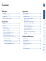
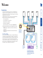
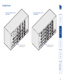
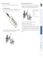
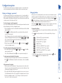
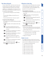
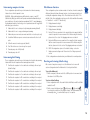
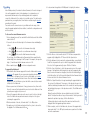
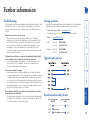
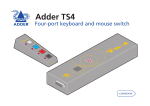
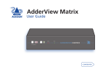
SmartView Multiscreen Serial Four-port KVM and serial switch SMARTVIEW MULTISCREEN Further information Troubleshooting.........................................................................18 Getting assistance.......................................................................18 Upgrade cable pin out...............................................................18 Synchronisation cable pin out...................................................18 Safety information.....................................................................19 Warranty.....................................................................................19 Emissions and Immunity.............................................................20 Locations.......................................................................................5 Mounting......................................................................................5 Making connections.....................................................................6 System connections ................................................................6 Peripheral connections............................................................8 Optional power supply connection........................................8 Remote control connections...................................................9 Channel switching via RS232 control......................................9 Cascading SmartView Multiscreen Serial units....................10 Cascade connections.........................................................10 Cascade system selection..................................................10 Synchronising SmartView Multiscreen Serial units..............11 Hot plugging and mouse restoration..............................12 Installation The SYSTEM readout..................................................................13 Selecting systems........................................................................13 Configuration options................................................................14 Setting (or changing) a password.........................................14 Changing hotkeys..................................................................14 Mouse button switching modes...........................................15 All channel/active channel cycling........................................15 Automatic screen saver.........................................................15 Autoscanning computer selection........................................16 Autoscanning dwell timing...................................................16 Miscellaneous functions........................................................16 Resetting and restoring default settings..............................16 Upgrading..............................................................................17 Introduction..................................................................................2 Serial line switching ...........................................................2 Standard items..............................................................................3 Additional and optional items.....................................................4 Operation Welcome Contents Welcome PC2 PC3 PC4 PC1 SMARTVIEW MULTISCREEN The display clearly shows which system is currently connected to the display(s) keyboard and mouse. The Adder SmartView Multiscreen Serial is a four-way KVM switch designed for systems using multiple touch screens. The unit allows a single keyboard, mouse and (up to) two video monitors to control four separate dual screen host systems. Switching between the systems connected to the Adder SmartView Multiscreen Serial can be achieved in five different ways: • The front panel button, • The optional Remote control selector, • Keyboard hotkey combinations, • Mouse button combinations, • By external serial device control using the OPTIONS/FLASH port. The Adder SmartView Multiscreen Serial is available in two models: • SVMS4-S supports a single video monitor and serial device per switched port, • SVMS4-DS supports dual video monitors and serial devices per switched port. Introduction 4 3 2 In common with all other Adder switches, the SmartView Multiscreen Serial provides completely transparent switching for the serial lines (in unison with the keyboard, video and mouse channels). Apart from the ground connections of each serial port (which remain permanently connected), all RS232 signal lines are switched. No baud rates or serial protocols need to be configured because no interpretation is made of the signals as they are cleanly passed through the unit. Serial line switching 1 Remote control allows the main unit to be neatly concealed away from view. The video display(s) with touch screen(s), keyboard and mouse are common to all of the systems and are electronically connected to the required one using any of four switching methods. Switching can be initiated from either the keyboard or mouse in addition to the unit or optional remote control. Standard items Adder SmartView Multiscreen Serial model SVMS4-DS Adder SmartView Multiscreen Serial model SVMS4-S 1D NA TIO OP WER PO 5V A 1 4C C 4B B 4A 3B 2B 1A 2A TIO OP NS 3D L /F R OO Y IND ONL E US 3A L L NA TIO OP WER PO A One video input and one serial channel per port 5V A 1 2C 1B 1A 4D 3C 2B 4C 3B 2A C 4B 3A B 4A D ION T OP A Two video inputs and two serial channels per port S/ FL H AS D 3C 1B 1C 4D R OO Y IND ONL E US 2C H AS 2D 3D 1C 2D 1D Additional and optional items PS/2-style keyboard/mouse cable, 2 metres (two required per system) CCP2U converter (required when connecting to a system that uses a USB keyboard and mouse - two VSC3 cables are also required) Adder P/N: CCP2U RC4 remote control plus link cable Adder P/N: VSC3 RC1 remote control plus link cable Flash upgrade link cable Converter for connecting a SUN computer to the Adder unit (not pictured) Adder P/N: CCSUN Optional power supply (required only when long cables are used or for a slave unit in synchronised mode) plus country-specific mains cable Adder P/N: PSU-IEC-5VDC Installation Before you begin connecting to the keyboard, mouse and source systems, it is advisable to mount the unit in place, either: • On a horizontal surface using the supplied self adhesive feet, or • Amongst the cabling at the rear of the desk. Please consider the following important points when planning the position of the Adder SmartView Multiscreen Serial unit: • Situate the Adder unit close to the systems to which it will be connected. The Adder unit does not require a power supply providing that its connection cables are no longer than 2 metres. • Thanks to the remote control, the Adder unit can be situated out of sight behind a desk or adjacent to the systems. • Consult the precautions listed within the Safety information section. Mounting Locations System connections To make keyboard and mouse links (PS/2-style connections) Note: Two Adder VSC3 link cables are required per connected system. 1 Ensure that the computer systems to be connected are switched off and that no power is applied to the Adder unit. (Note: If it is not possible to switch off systems prior to connection, then a ‘Hot plug’ procedure is available – see the Hot plugging and mouse restoration section for more details). 2 At the rear panel of the Adder unit, attach a VSC3 link cable to the (purple) keyboard socket of port 1. 2B 1A T OP 2A Symbols indicate the keyboard and mouse sockets Adder CCP2U converter 3 Attach the other end of the VSC3 link cable to the keyboard socket (usually coloured purple) on the first system. 4 Repeat steps 1 and 2 for the mouse connection (green) between the Adder unit port 1 and the first system. Note: For neatness and accessibility it is advisable to join the keyboard and mouse link cables, that lead to each system, using several cable ties. 5 Repeat the above steps for systems 2, 3 and 4 to the corresponding ports of the Adder unit. If any systems do not have PS/2-style keyboard and mouse connectors, please use an Adder CCP2U converter, as discussed opposite. 1B Keyboard and mouse link cables from Adder unit USB port on system Note: For neatness and accessibility it is advisable to join the keyboard and mouse link cables, that lead to each system, using several cable ties. 4 Attach the USB connector of the CCP2U converter to a vacant USB socket of the computer system. 5 Repeat the above steps for any other system that requires USB connections. 2C To make keyboard and mouse links (USB-style connections) Note: Two Adder VSC3 link cables plus one CCP2U converter are required per connected system. 1 At the rear panel of the Adder unit, attach a VSC3 link cable to the (purple) keyboard socket of the required port. 2 Attach the other end of the VSC3 link cable to the inline keyboard socket of the CCP2U converter. 3 Repeat steps 1 and 2 for the mouse connection (green) between the Adder unit port and the CCP2U converter. Connections to the Adder unit do not need to follow the precise order given in this user guide, although if one or more systems must be hot-plugged, connect these after all other connections have been made. Making connections To make serial links 1 Ensure that the computer systems to be connected are switched off and that no power is applied to the Adder unit. (Note: If it is not possible to switch off systems prior to connection, then a ‘Hot plug’ procedure is available – see the Hot plugging and mouse restoration section for more details). 2 At the rear panel of the Adder unit, connect a serial link cable to socket B of port 1 (D-type, male, 9 way socket). Ensure that the securing screws are used to maintain a reliable link. To make video links 1 Ensure that the computer systems to be connected are switched off and that no power is applied to the Adder unit. (Note: If it is not possible to switch off systems prior to connection, then a ‘Hot plug’ procedure is available – see the Hot plugging and mouse restoration section for more details). 2 At the rear panel of the Adder unit, connect a video link cable to socket A of port 1. Ensure that the securing screws are used to maintain a reliable link. 1D LA /F SH 1A 1C 1B O IO PT NS SH LA /F 1A 3 Connect the plug at the other end of the video link cable to the corresponding video output socket of the host computer. 4 If a second video channel from the same system is to be used, repeat steps 2 and 3 for the socket C of port 1 (SVMS4-DS models only). 5 Repeat all of the above steps for each port to be used. 3 Connect the plug at the other end of the serial link cable to the corresponding serial socket of the host computer. 4 If a second serial link from the same system is to be used, repeat steps 2 and 3 for the socket D of port 1 (SVMS4-DS models only). 5 Repeat all of the above steps for each port to be used. NS O IO PT 1C 1B 1D B NA TIO OP WER PO 4A L A 5V A 1 P 2C 4D 3C 2B 4C 3B 2A C 4B 3A B 4A D A 3D R OO Y IND ONL E S U NA TIO OP WER PO 5V A 1 4D 3C D 4C 3B C 4B 3A B 4A L A Optional power supply connection Note: The Adder unit can obtain its power from the keyboard connections of any of the four connected systems. Thus, an external power supply is not required unless the connection cables used exceed 2 metres. Important: Please read and adhere to the electrical safety information given within the Safety information section 4D of this guide. In particular, do not use R OO Y an unearthed power socket or extension IND ONL D E 4C US cable. To connect the optional power supply 1 Attach the output connector of the power supply (country specific power supplies are available) to the socket on the far left of the rear panel of the Adder unit. 2 When all other connections have been made, connect the main body of the power supply to a nearby earthed mains socket. L NA TIO OP WER PO 5V A 1 C 4B B 4A A 3D 3C 3B 3A 5V A 1 To connect video monitors 1 At the rear panel of the Adder unit, attach the connector from the primary video monitor to blue socket A within the common section on the left side (closest to the power input socket). 2 If a second video monitor is to be used, repeat step 1 for the socket C within the common section on the left side (closest to the power input socket) (SVMS4-DS models only). 4 3D To connect a keyboard and mouse 1 At the rear panel of the Adder unit, attach the connector from the keyboard to the purple socket within the common section on the left side (closest to the power input socket). 2 Attach the connector from the mouse to the green socket within the common section on the left side (closest to the power input socket). To connect serial (touch screen) devices 1 At the rear panel of the Adder unit, attach the connector from the primary serial (touch screen) device to socket B R OO Y IND ONL within the common section on E US the left side. 2 If a second serial device is to be used, repeat step 1 for the socket D within the common section on the left side L NA TIO (SVMS4-DS models only). OP W ER O Peripheral connections The remote control unit can be used to provide manual switching between systems. To connect the remote control 1 Locate the remote control unit and the remote control cable. Attach the smaller of the two cable connectors to the socket at the rear of the remote control. Channel switching via RS232 control The Adder SmartView Multiscreen Serial can be controlled by a remote RS232 serial device. To do this, the serial device must be connected to the OPTIONS/ FLASH port on the rear panel of the unit using an appropriate link cable. 1C 1B 1A O IO PT NS LA /F SH Pin assignments for the OPTIONS/ FLASH port on the rear panel are as follows: Pin 9 = GND Pin 10 = TXD Pin 11 = RXD Remote control connections 2 At the other end of the cable, attach the larger connector to the OPTIONS/ FLASH socket on the right side of the Adder unit rear panel. The serial device must use the following speed/protocol settings: 1200 baud, 8 bits, no parity and 1 stop bit. No handshaking is used by the SmartView Multiscreen Serial. To perform the switching operation, simply send the character for the required channel, for example ASCII ‘1’ (hex code 31) will select channel 1, ASCII ‘2’ (hex code 32) will select channel 2 and so on. The SmartView Multiscreen Serial will echo the ASCII character back to the sending device when the channel has been changed. Other pins to be left unconnected. 1A O IO PT NS LA /F SH 1B 1C Cascading SmartView Multiscreen Serial units INDOOR USE ONLY The quickest way to access cascaded systems is to use hotkey sequences. 1 Simultaneously press and hold and . Note: The and keys when pressed in combination are called ‘hotkeys’ and they signal to the Adder unit that you wish to control it, rather than the computer. However, if these particular hotkeys clash with another device or program, then you can change them to a different combination. 2 While still holding and , press the first numeral of the required port address, then: • If the port address is a single character, release all of the keys. • If the port address is two or more characters, release the first numeral key and press the second – repeat this procedure until all of the port address numerals have been entered, then release and . Note: The numbers on your keyboard’s numeric keypad are not valid, use only the numeral keys above the QWERTY section. The address of each system is determined by the port of the Adder unit to which it directly connected and also the number(s) or the port(s) to which its Adder unit is cascaded into other Adder units above. For instance, on the link diagram shown opposite, the computer system connected to port 3 of the lower Adder unit would be addressed as 43. This is because the lower Adder unit is cascaded through port 4 of the upper Adder unit. OPTIONAL POWER 5V 1A D 4D 3D 2D 1D C 4C 3C 2C 1C B 4B 3B 2B 1B A 4A 3A 2A 1A PC1 PC2 PC3 OPTIONS / FLASH Cascade link PC41 PC42 PC43 PC44 INDOOR USE ONLY OPTIONAL POWER 5V 1A D 4D 3D 2D 1D C 4C 3C 2C 1C B 4B 3B 2B 1B A 4A 3A 2A 1A OPTIONS / FLASH Cascade system selection To cascade Adder units: the sockets of a system port (1 to 4) on one Adder unit must be connected to the sockets of the common port of the Adder unit below. The cascade link is shown in light orange on the diagram. Computer systems can be attached to all vacant ports that are not being used as cascade links. When cascading Adder units in this way, a power adapter (PSU-IEC-5VDC) must be connected to each unit. Cascade connections These Adder units can be linked in a cascade formation to allow more computer systems to be controlled. SmartView Multiscreen Serial units can be connected in a cascaded tree structure. This can be particularly useful where clusters of computers are located some distance from each other because each unit acts as data booster and can each be up to 30 metres away from the next SmartView Multiscreen Serial. 10 INDOOR USE ONLY OPTIONAL POWER 5V 1A 4D 3D 2D 1D C 4C 3C 2C 1C B 4B 3B 2B 1B A 4A 3A 2A 1A PC2 OPTIONS / FLASH PC1 Computer systems Synchronisation cable (see page 18 for cable pin-out) INDOOR USE ONLY Slave unit OPTIONAL POWER 5V 1A D 4D 3D 2D 1D C 4C 3C 2C 1C B 4B 3B 2B 1B A 4A 3A 2A 1A Master unit D OPTIONS / FLASH Adder SmartView Multiscreen Serial units are available in two forms: • SVMS4-S units support a single video display • SVMS4-DS units support two video displays Where more video monitors are required, you can connect two Adder SmartView Multiscreen Serial units (of the same type) together to switch twice the number of video and serial channels. The various video outputs from each system are shared between corresponding ports of the two Adder units, with their keyboard and mouse connections going only to the master Adder unit. A synchronisation cable is then connected between the OPTIONS/FLASH ports of the two Adder units (see page 18 for pinout details). Whenever the master Adder unit’s channel is switched, it sends a command to the slave unit to make it do the same. The slave unit requires the optional power adapter because it does not have keyboard connections to either of the systems. The SmartView Multiscreen Serial may also be synchronised together with AdderView GEM products as their OPTIONS ports operate in the same way. Use any of the standard methods to switch between channels. Synchronising SmartView Multiscreen Serial units 11 The general rule is that unless both the mouse and the driver are both IntelliMouse compatible then you need to restore the mouse as ‘PS/2’. An IntelliMouse can operate in either mode, whereas a PS/2 mouse cannot. Recognising an IntelliMouse-style mouse The IntelliMouse format was introduced to support, among other features, the scroll wheel function. If the mouse has a scroll wheel, then it is likely to support the IntelliMouse format. If it is a Microsoft-branded mouse, then it will usually state that it is an IntelliMouse on its underside label. Recognising an IntelliMouse driver Before hot plugging to the Adder unit (or afterwards using only keyboard control), access the Windows Control Panel of the system and select either the Mouse option (on Windows NT, 2000 and XP) or the System option (on Windows 95, 98, ME). Look for the name of the driver, which will usually include the words PS/2 or IntelliMouse. Which restore setting do I use? To restore mouse operation when hot plugging: 1 Using link cables, carefully make the keyboard and mouse connections between the host system and the appropriate ports on the Adder unit. 2 Press and hold the SELECT button on the Adder unit front panel for five seconds, until the SYSTEM readout shows C (Configuration mode). 3 Choose one of the following actions: • To restore a standard PS/2-style mouse: Press • To restore an IntelliMouse: Press The SYSTEM readout will show the entered characters and then return to show C when you press . The mouse restoration should now be complete. Note: The restore functions predict the likely mouse resolution settings but may not restore the exact speed or sensitivity settings that were originally set. 4 Move the mouse a short distance and check for appropriate on-screen cursor movement. If the mouse cursor darts erratically around the screen, then cease moving the mouse. This is an indication that the chosen restore function is incorrect. Try again using the other restore function. 5 To exit from Configuration mode, press . It is strongly recommended that you switch off a host system before attempting to connect it to the Adder unit. However, if this is not possible then you need to ‘hot plug’ the system while it is still running. There is not normally a danger of damage to the system, however, when PS/2-style mouse or IntelliMouse communications (i.e. non-USB) are interrupted, often they fail to re-initialise when reconnected. The Adder unit provides a feature to reinstate mouse communications once the necessary connections have been made. There are two main types of data formats used by current non-USB mice, these are the older ‘PS/2’ format and the more recent ‘IntelliMouse®’ format introduced by Microsoft. These use slightly different data arrangements and it is important to know which type was being used before you hot-plugged the system to the Adder unit. The previous setting depends both on the type of mouse and the type of driver, as various combinations of PS/2 and IntelliMouse are possible. Using the incorrect restore function may produce unpredictable results and require the system to be re-booted. Hot plugging and mouse restoration 12 Operation Main digit indicates currently selected system or other modes - see below for details. Flashing dot indicates keyboard and/or mouse activity. configuration mode, upgrade mode, etc. Typical SYSTEM readout displays are: , , or Indicates the currently selected system. The selected channel will also be indicated on the remote control. The Adder unit is disabled, no system is currently selected. The remote control will not show any channel indication. The Adder unit is password protected. You must enter the current password to gain access. See Setting (or changing) a password for details. The remote control will not show any channel indication. Configuration mode is currently active. Press to exit. See Configuration options for details. The remote control will not show any channel indication. Upgrade mode is currently active. See Upgrading for details. The remote control will not show any channel indication. The upgrade process is complete. Set mini switch 7 to OFF to exit upgrade mode. To use the remote control selector • Press the remote control button that corresponds to the required system. The adjacent indicator will illuminate to show that the chosen system is selected. To use keyboard hotkey combinations Note: The standard hotkeys can be changed to avoid clashes with software applications, see Changing hotkeys for details. • To select a particular system: Press and hold the hotkeys (usually and ), then also press the number of the required system and release all three keys. • To select the next/previous system: Press and hold the hotkeys (usually and ), then press and release the key until the required system is selected. Release the hotkeys. Note: You can determine whether the Adder unit visits every port in turn (regardless of whether active systems are connected to them) or only those with active systems connected. See All channel/active channel cycling for details. To use mouse button combinations Note: The mouse button arrangements can be changed, see Mouse button switching modes for details. • Press and hold the mouse scroll wheel (or centre mouse button) and then press either the left mouse button to change to the next system or the right mouse button to change to the previous system. To use the Adder unit front panel button Note: You can determine whether the Adder unit visits every port in turn (regardless of whether active systems are connected to them) or only those with active systems connected. See All channel/active channel cycling for details. • Press the SELECT button repeatedly until the SYSTEM readout shows the required system number. On the front panel of the Adder unit, the SYSTEM readout indicates either: • The computer system to which the keyboard and mouse are connected, or • An alternative mode of operation, such as password protected mode, There are four ways to select a system: • The Adder unit front panel button • The optional Remote control selector • Keyboard hotkey combinations • Mouse button combinations The SYSTEM readout Selecting systems In operation, the Adder unit allows you to quickly switch between up to four systems. One system can be accessed at a time, whereupon the common keyboard, mouse, video monitors and serial channels are linked to that system. The Adder unit deceives the other systems that they still have their peripherals connected to them in order that they respond quickly and correctly once they are again selected. 13 Configuration options The Adder unit provides numerous configuration options to ensure that it best suits your circumstances and the tasks carried out by the connected systems. To lock the system (invoking password protection) • Press and hold the hotkeys (usually and ) and press . The SYSTEM readout should show p. Note: If the SYSTEM readout shows , there is no password currently set. To enter a password and unlock the system 1 Enter the current password (upper and lower cases are not differentiated). 2 Press . The SYSTEM readout should show the number of the first available system. If the password is forgotten 1 Remove power from the Adder unit. If any systems are active, either switch them off or remove their keyboard link connectors from the Adder unit. If an optional power supply is used, remove it. 2 Press and hold the SELECT button and re-apply at least one source of power. The SYSTEM readout will show C to signify that configuration mode is active. 3 Follow the standard procedure ‘To set (or change or cancel) a password’ from step 2 to create a new password. To change the hotkeys 1 Enter configuration mode: Press and hold the SELECT button until the SYSTEM readout shows C. 2 Press followed by a number to select the required hotkey setting, as follows: ‘CTRL’ and ‘ALT’ keys together (default) ‘CTRL’ and ‘SHIFT’ keys together ‘ALT’ and ‘SHIFT’ keys together ‘RIGHT ALT’ key ‘LEFT ALT’ and ‘RIGHT ALT’ keys together ‘LEFT CTRL’ and ‘LEFT ALT’ keys together ‘RIGHT CTRL’ and ‘RIGHT ALT’ keys together No hotkey enabled 3 When the hotkey combination selection has been made, press to fix it and press to exit from configuration mode. To set (or change or cancel) a password Note: If the SYSTEM readout shows p then the current password must be entered before attempting to enter the configuration mode. 1 Enter configuration mode: Press and hold the SELECT button until the SYSTEM readout shows C. . The SYSTEM readout will show = to indicate that you should 2 Press enter your new password. Note: The password is not case sensitive and can be any combination of keystrokes including the function keys but excluding , , and . Note: To cancel the password protection function, do not enter any characters, merely press . to fix it and press to 3 When the password has been entered, press exit from configuration mode. Hotkeys are two normal keyboard keys that, when pressed simultaneously with a third key, signal to the Adder unit that you are sending a message specifically to it and not to the currently selected system. The hotkeys are ordinarily and , while a third keypress determines what you want the Adder unit to do, e.g change to different system, invoke password protection, etc. If the standard and hotkeys are also needed for computer system tasks, you can change them for another combination, as discussed below. The password option allows you to quickly impose a level of security suitable to prevent system tampering while you are away from your desk for short periods. When enabled, the Adder unit will default to protected mode when switched on or when you press the hotkeys and L (lock). Changing hotkeys Setting (or changing) a password 14 To change SELECT button channel cycling 1 Remove power from the Adder unit. If any systems are active, either switch them off or remove their keyboard link connectors from the Adder unit. If an optional power supply is used, remove it. 2 On the rear panel, click mini switch 6 to the required position, as follows: • To cycle between all system ports, set switch 6 to OFF. • To cycle between active ports only, set switch 6 to ON. 3 Re-apply power to the Adder unit. Automatic screen saver These configuration options allow you to blank the screen after a set period of time has elapsed since the keyboard or mouse were last used. Power saving monitors can sense the screen blanking action and change to sleep mode. B1 Screen blanking feature disabled (default setting). B2 Blank screen after 1 minute of inactivity. B3 Blank screen after 2 minutes of inactivity. B4 Blank screen after 4 minutes of inactivity. B5 Blank screen after 8 minutes of inactivity. B6 Blank screen after 12 minutes of inactivity. B7 Blank screen after 16 minutes of inactivity. B8 Blank screen after 20 minutes of inactivity. To change keyboard/mouse channel cycling 1 Enter configuration mode: Press and hold the SELECT button until the SYSTEM readout shows c. 2 Press followed by a number to select the required keyboard/mouse channel cycling setting, as follows: Cycle between all ports when switching with ‘hotkeys and Tab’ or three button mouse (default). Cycle between active ports only when switching with ‘hotkeys and Tab’ or three button mouse (default). 3 When the channel cycling selection has been made, press to fix it and then press to exit from configuration mode. The Adder unit provides the option, when cycling between the system channels, to visit each channel (irrespective of whether an active system is connected) or to only select active channels. You can affect the keyboard/mouse setting independently from the front panel SELECT switch setting. To change the mouse button switching modes 1 Enter configuration mode: Press and hold the SELECT button until the SYSTEM readout shows c. 2 Press followed by a number to select the required mouse button setting, as follows: System channels are switchable using a 3-button mouse or IntelliMouse (default). Adder unit reports 2-button mouse mode to the systems. System channels are not switchable using the mouse. Adder unit reports 2-button mouse mode to the systems. System channels are not switchable using the mouse. Adder unit reports 3-button mouse mode to the systems. System channels are switchable using a 3-button mouse or IntelliMouse (default). Adder unit reports IntelliMouse mode to the systems. System channels are not switchable using the mouse. Adder unit reports IntelliMouse mode to the systems. 3 When the mouse button selection has been made, press to fix it and then press to exit from configuration mode. All channel/active channel cycling You can use a three button mouse to switch between systems. However, when used in this way, the action of the middle mouse button or scroll wheel click is ‘trapped’ by the Adder unit and is not passed to the system. This makes it unavailable for use in controlling applications on the selected system. The scroll wheel scrolling action is unaffected and passed on normally to the systems, only the scroll wheel click is used by the Adder unit. • To use the mouse buttons to change systems, use options U1 (default) or U4. • To use the scroll wheel click/third mouse button with the systems, use options U3 or U5. • To report only a simple 2-button mouse to the systems, use option U2. Mouse button switching modes 15 These configuration options allow you to determine how long the autoscanning feature dwells at each computer when scanning between them. T1 Dwell at each computer for 2 seconds before switching to the next port (default setting). T2 Dwell at each computer for 5 seconds before switching to the next port. T3 Dwell at each computer for 7 seconds before switching to the next port. T4 Dwell at each computer for 10 seconds before switching to the next port. T5 Dwell at each computer for 15 seconds before switching to the next port. T6 Dwell at each computer for 20 seconds before switching to the next port. T7 Dwell at each computer for 30 seconds before switching to the next port. T8 Dwell at each computer for 60 seconds before switching to the next port. Resetting and restoring default settings On occasions it may be necessary to reset the Adder unit or to remove all custom settings and return the Adder unit to its factory default state. To reset the Adder unit 1 On the rear panel, click mini switch 8 to its ON position for a moment and then return it to its OFF position. To restore default settings 1 Enter configuration mode: Press and hold the SELECT button until the SYSTEM readout shows c. and then press , followed by 2 On the connected keyboard, press to perform the restoration of the default settings. The SYSTEM readout will momentarily show to confirm that the process is complete. These configuration options contain a mixture of functions, from discovering the Adder unit internal software (firmware) revision, to restoring mouse function, to resetting all configuration changes. Note: These functions use the letter ‘F’. As with all of the other configuration options, press the letter and then the number, i.e. F and then 1 – not the ‘F1’ function key. F1 Display firmware first digit F2 Display firmware second digit F3 Display firmware third digit F5 Restore PS/2 mouse operation to the currently selected computer that has ceased to respond to mouse movement. Note: Before using this function, please refer to the section ‘Hot plugging and mouse restoration’ F6 Restore IntelliMouse mouse operation to the currently selected computer that has ceased to respond to mouse movement. Note: Before using this function, please refer to the section ‘Hot plugging and mouse restoration’ F8 RESET all configuration options to the default settings - see below. P Initiates password setting mode. Please refer to the ‘Using a password’ section. E Exits configuration mode and returns your Adder unit to normal operation. Autoscanning dwell timing Miscellaneous functions These configuration options allow you to determine how the autoscanning feature chooses which computer to view. WARNING - When switching between different video sources, some CRT (Cathode Ray Tube) type monitors will operate an internal mechanical relay at every switchover - this can be heard as a mechanical ‘click’. To avoid damaging the mechanical contacts of such relays, do not operate autoscan for long periods with these types of monitors. L1 Adder unit locks on to active ports only during autoscanning (default). L2 Adder unit locks on to every port during autoscanning. L3 Adder unit powers on in autoscan mode and locks on to active ports only. L4 SmartView Multiscreen powers on in autoscan mode and locks on to all ports. L5 Allow the mouse to run at any speed (default). L6 Don’t allow the mouse to run at very slow speeds. L7 Cascade query code = AD (default). L8 Cascade query code = EF. Autoscanning computer selection 16 6 Locate and run the application ‘KVMUploader’ to display this window: To upgrade the Adder unit 1 Download the latest firmware upgrade file from the Adder website: www. adder.com. The upgrade files are compressed using pkzip format which you will need to decompress them. If you do not have pkzip, go to www. pkware.com to download the latest version. Place the decompressed upgrade files onto the Windows system that will be connected (via a vacant serial port) to the Adder unit. 2 Remove power from the Adder unit. If any systems are active, either switch them off or remove their keyboard link connectors from the Adder unit. If an optional power supply is used, remove it. 3 Connect the upgrade cable between the remote control socket on the right side of the Adder unit rear panel and a vacant serial port on the system containing the upgrade files. 4 On the underside of the unit, click mini switch 7 to its ON position. 5 Re-apply power to the Adder unit and switch on the system to be used for the upgrade. The SYSTEM readout will show . 7 Click the Browse... button and locate the TXT file that accompanied the upgrade utility. Highlight the TXT file and click the Open button. 8 Click the Advanced... button and in the subsequent dialog, ensure that the Serial Port entry matches the port to which the upgrade cable is attached. Also select the Program and verify option. Click the OK button. 9 Click the Query Unit button to check the name and version of the current firmware - the application will interrogate the unit via the upgrade cable. Once the version information is displayed, check that the Intended Target Units field matches the Unit Connected field and the New Firmware Version field exceeds that of the Current Firmware Version. 10Click the Upload Now button to begin transferring the upgrade data from the system to the Adder unit. The progress of the upload is shown in the status bar (indicating the advancement of the current task) and the progress bar (indicating the progress of the upload as a whole). The SYSTEM readout will show u. During the upload, all buttons become disabled except for the Abort button. The upload can take as long as fifteen minutes. Should you need to abandon the upload at any stage, click the Abort button. Following the upload, a verification will be carried out and the results displayed within the upgrade application window. 11When complete, switch off the Adder unit, disconnect the upgrade cable, return mini switch 7 to its OFF position and resume operation of the Adder unit in the usual manner. To discover the current firmware version 1 Enter configuration mode: Press and hold the SELECT button until the SYSTEM readout shows c. 2 You need to discover the three digits of the firmware release individually, as follows: to discover the first firmware release digit. • Press • Press to discover the second firmware release digit. • Press to discover the third firmware release digit. At each stage, the SYSTEM readout will momentarily show = and then the relevant digit, before returning to the c prompt. For example, the respective digits 1, 4 and 6 mean that the firmware version is v1.46. 3 Once completed, press to exit from configuration mode. Like all Adder products, the internal software (firmware) of the unit is designed to be easily upgraded in order to take advantage of a continual process of improvement and innovation. A specialised upgrade cable is required to connect the Adder unit to the serial port of a suitable system. The cable may be purchased from your supplier, direct from Adder or created using the pin-out given later in this guide. You can discover the current version of your Adder unit in two ways, either using the upgrade application (discussed later) or within the configuration mode as discussed next. Upgrading 17 Further information Keyboard does not function or functions intermittently. Num lock light does not always come on when the num lock key is pressed. • Some older keyboards were designed for use with specific systems and are not truly AT or PS/2 compatible. These are not common but if you experience problems try another keyboard. • Email [email protected] • Fax in the UK: in the US: 01954 780081 +1 888 275 1117 • Phone in the UK: in the US: 01954 780044 +1 888 932 3337 Upgrade cable pin out Mouse causes channel to change. • Some cheaper mice are not fully compatible with the Adder unit and can lose data causing the channel to be changed (if mouse switching of channels is enabled). Ensure that you are using a Microsoft compatible mouse driver on your system. Some other manufacturers’ drivers may switch the mouse to use a proprietary mouse data format not supported by the Adder unit. If you have unplugged and re-connected a mouse to the Adder unit then ensure that you reset it using the mouse reset function. Mouse jumps around the screen after disconnecting the mouse cable or powering down the Adder unit. • The mouse data format may be out of synchronisation with that required by the system (PS/2 or Intellimouse). Try the ‘restore Intellimouse’ function (F6) to resolve the problem or repower the system. • Adder Technology website – www.adder.com Check the Support section of our website for the latest solutions. Mouse does not move cursor on screen. • If you move the mouse and the activity indicator (dot on 7 segment display) does not flash then the Adder unit is not receiving data from the mouse. Check the mouse connection to the Adder unit, try resetting the mouse using the reset function or re-powering the Adder unit. If you are attempting to connect the Adder unit to a system with a PS/2 mouse connection that has not been powered down then you will need to use the mouse restoration functions. If you are still experiencing problems after checking the list of solutions in the Troubleshooting section then we provide a number of other solutions: If you experience problems when installing or using the Adder unit, please check through this section for a possible solution. If your problem is not listed here and you cannot resolve the issue, then please refer to the ‘Getting assistance’ section. Getting assistance Synchronisation cable pin out 15-way D-type male MASTER TXD 10 RXD 11 GND 9 15-way D-type male SLAVE 11 RXD 9 GND Troubleshooting 18 Adder Technology Ltd warrants that this product shall be free from defects in workmanship and materials for a period of two years from the date of original purchase. If the product should fail to operate correctly in normal use during the warranty period, Adder will replace or repair it free of charge. No liability can be accepted for damage due to misuse or circumstances outside Adder’s control. Also Adder will not be responsible for any loss, damage or injury arising directly or indirectly from the use of this product. Adder’s total liability under the terms of this warranty shall in all circumstances be limited to the replacement value of this product. If any difficulty is experienced in the installation or use of this product that you are unable to resolve, please contact your supplier. • For use in dry, oil free indoor environments only. • Not suitable for use in hazardous or explosive environments or next to highly flammable materials. • The optional power adapter is only required when the link cables used exceed 2 metres in length. Otherwise the Adder unit can derive its power from any of the host systems via the keyboard connections. • Warning – the optional power adapter contains live parts. • No user serviceable parts are contained within the optional power adapter - do not dismantle. • Do not use the optional power adapter if the power adapter case becomes damaged, cracked or broken or if you suspect that it is not operating properly. • Replace the optional power adapter with a manufacturer approved type only. • If you use a power extension cable, make sure the total ampere rating of the devices plugged into the extension cable do not exceed the cable’s ampere rating. Also, make sure that the total ampere rating of all the devices plugged into the wall outlet does not exceed the wall outlet’s ampere rating. • Do not attempt to service the Adder unit or its remote control yourself. • The optional power adapter can get warm in operation – do not situate it in an enclosed space without any ventilation. • The Adder unit does not provide ground isolation and should not be used for any applications that require ground isolation or galvanic isolation. • When using the optional power adapter, use only with a grounded outlet. When using a backup power supply (UPS), power the computers, the monitors and the Adder unit from the same supply. Warranty Safety information 19 Emissions and Immunity All interface cables used with this equipment must be shielded in order to maintain compliance with radio frequency energy emission regulations and ensure a suitably high level of immunity to electromagnetic disturbances. This equipment generates, uses and can radiate radio frequency energy and if not installed and used properly, that is, in strict accordance with the manufacturer’s instructions, may cause interference to radio communication. It has been tested and found to comply with the limits for a class A computing device in accordance with the specifications in Subpart J of part 15 of FCC rules, which are designed to provide reasonable protection against such interference when the equipment is operated in a commercial environment. Operation of this equipment in a residential area may cause interference, in which case the user at his own expense will be required to take whatever measures may be necessary to correct the interference. Changes or modifications not expressly approved by the manufacturer could void the user’s authority to operate the equipment. This equipment does not exceed the class A limits for radio noise emissions from digital apparatus set out in the radio interference regulations of the Canadian Department of Communications. Le présent appareil numérique n’émet pas de bruits radioélectriques dépassant les limites applicables aux appareils numériques de la classe A prescrites dans le règlement sur le brouillage radioélectriques publié par le ministère des Communications du Canada. Canadian Department of Communications RFI statement This equipment has been tested and found to comply with the limits for a class A computing device in accordance with the specifications in the European standard EN55022. These limits are designed to provide reasonable protection against harmful interference. This equipment generates, uses and can radiate radio frequency energy and if not installed and used in accordance with the instructions may cause harmful interference to radio or television reception. However, there is no guarantee that harmful interference will not occur in a particular installation. If this equipment does cause interference to radio or television reception, which can be determined by turning the equipment on and off, the user is encouraged to correct the interference with one or more of the following measures: (a) Reorient or relocate the receiving antenna. (b) Increase the separation between the equipment and the receiver. (c) Connect the equipment to an outlet on a circuit different from that to which the receiver is connected. (d) Consult the supplier or an experienced radio/TV technician for help. FCC Compliance Statement (United States) European EMC directive 89/336/EEC 20 Adder Corporation, 29 Water Street, Newburyport, MA 01950, United States of America Tel: +1-888-932-3337 Fax: +1-888-275-1117 Adder Technology Limited, Technology House, Trafalgar Way, Bar Hill, Cambridge, CB3 8SQ, United Kingdom Tel: +44 (0)1954 780044 Fax: +44 (0)1954 780081 © 2007 Adder Technology Limited All trademarks are acknowledged. Release 1.0d July 2007 Part No. ADD0069 Documentation by: www.ctxd.com 21