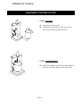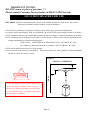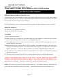
1
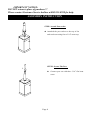
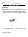
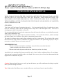
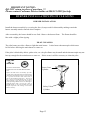
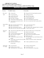
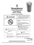
Virco Associates, Inc.
145, Brea Canyon Road
Walnut, CA 91789, U.S.A.
GAS-FIRED INFRARED
OUTDOOR PATIO HEATER
INSTALLATION, OPERATION
MAINTENANCE INSTRUCTIONS
FOR MODEL PTH106-SS
TABLE OF CONTENTS
PAGE
IMPORTANT ……………………………………………………………………
1
TOOLS & PARTS ………………………………………………………………..
2
PRECAUTIONS…………………………………………………………………..
3
ASSEMBLY INSTRUCTIONS ………………………………………………….
4
GAS REQUIREMENTS & LEAK TESTING …………………………………..
7
SAFETY CHECKS ……………………………………………………………….
8
LOCATING HEATER FOR USE ……………………………………………….
9
LIGHTING / SHUTDOWN ……………………………………………………….
10
STORAGE / BURNER REMOVAL………………………………..…………….
12
BURNER INSTALLATION / PILOT CLEANING ………………………………
13
BURNER REMOVAL …………………………………………………………….
14
TROUBLE SHOOTING .…………………………………………………………
15
PARTS LIST ………………………………………………………………………
16
WARRANTY ………………………………………………………………………
17
READ THE FOLLOWING INSTRUCTIONS CAREFULLY AND BE SURE YOUR PATIO HEATER IS
PROPERLY INSTALLED, ASSEMBLIED AND CARED FOR. FAILURE TO FOLLOW THESE
INSTRUCTIONS MAY RESULT IN SERIOUS BODILY INJURY AND/OR PROPERTY DAMAGE. IF
YOU HAVE QUESTIONS CONCERNING ASSEMBLY OR OPERATION, CONSULT YOUR
DEALER, GAS APPLIANCE SERVICE REPRESENTATIVE OR YOUR GAS COMPANY.
NOTE TO INSTALLER:
LEAVE THESE INSTRUCTIONS WITH THE CONSUMER AFTER INSTALLATION.
NOTE TO THE CONSUMER:
RETAIN THESE INSTRUCTIONS FOR FUTURE REFERENCE.
STOP
PLEASE CONTACT 1-800-913-8999 FOR ASSISTANCE
DO NOT RETURN TO PLACE OF PURCHASE
IMPORTANT NOTICE:
DO NOT return to place of purchase!!!
Please contact Customer Service hotline at 800-913-8999 for help.
IMPORTANT
* * * WARNING * * *
For outdoor use only (outside any enclosure)
Improper operation, installation, adjustment, alteration,
servicing or maintenance can cause severe property
damage or serious injury or death. Please read the
installation, operation & maintenance instructions
thoroughly before installing or servicing this equipment.
* * * FOR YOUR SAFETY * * *
If you smell gas:
Shut off gas to appliance.
Extinguish any open flame.
If odor continues, immediately call your gas
supplier.
For your safety:
Do not store or use gasoline or other flammable vapor
and liquids in the vicinity of this or any other appliance.
Page 1
TOOLS AND PARTS NEEDED FOR ASSEMBLY
NOTE: 20 pound, 5 Gallon LPG Tank is not supplied
Tools Needed:
Adjustable Opening Wrench
Spray Bottle of Soapy Water (To check for leaks)
Parts Supplied:
Reflector (1)
Heater Head Assembly (1)
Post Assembly (2)
Gas Tank Enclosure Assembly (2)
LPG Gas regulator with Hose (1)
Tank Hook (1)
Hardware Bag
Post Socket 1/4” Acorn-cap (4)
Post 3/16” Flat Head Screw (3)
Reflector 1/4” Acorn-cap (4)
Reflector 1/4” Flat Washer (4)
Heater Head 3/16” Truss Head Screw (4)
For Service Questions Replacement parts or other assistance, Please call VAI Customer Service Hotline at:
VAI
145 Brea Canyon Road
Walnut, CA 91789
(800) 913-8999
Page 2
IMPORTANT NOTICE:
DO NOT return to place of purchase!!!
Please contact Customer Service hotline at 800-913-8999 for help.
PRECAUTIONS
NOTE: PLEASE READ THE FOLLOWING SAFETY
Do not use this space heater in an
explosive atmosphere. Keep heater away
from areas where gasoline or other
flammable liquids or vapors are stored.
Prior to use, check for damaged parts
such as hoses regulators, pilot or burner.
Do not attempt to alter unit in any manner.
EXAMPLE: using the heater without the
top canopy reflector or radiant screen. Do
not shorten the burner post assembly.
Heater must always be placed on a solid
and level surface.
Always maintain proper clearance to
combustible materials.(Top 36" Side 36")
Always assure there is ample fresh air
ventilation for outdoors use ONLY.
Never replace or substitute the regulator
with any regulator other than the factory
suggested replacement.
Do not clean heater with cleaners that are
combustible or corrosive.
Do not paint radiant screen, control panel
or top canopy reflector.
All leak test should be done with a soapy
solution. NEVER USE AN OPEN
FLAME TO CHECK FOR LEAKS.
The LP tank should be turned off when
the heater is not in use.
At least once a year, the unit should be
inspected for the presence of spiders,
spider webs or other insects. The burner
area is a common spider haven and can
damage the heater and render it unsafe
for use, Check the heater immediately if
any of the following exists:
1. The smell of gas in conjunction with
extreme yellow tipping of the burner
flames.
2. The heater does not reach temperature.
3. The burner makes popping noise during
use (a slight popping noise is normal
when the burner is extinguished).
The LP regulator/hose assembly shall be
located out of pathways where people
may trip over it or in area where the hose
will not be subject to accidental damage.
Children and adults should be aware of
hazards of high surface temperature and
shall stay away to avoid burns of clothing
ignition.
Young children should be carefully
supervised when they are in the area of
the heater.
Clothing or other flammable material
should not be hung from the heater, or
placed on or near the heater.
Any guard or other protective device
removed for servicing the heater must be
replaced prior to operating the heater.
Installation and repair should be done by
a qualified service person, the heater
must be should be inspected before use
and at least annually by a qualified
service person. More frequent cleaning
may be required as necessary. It is
imperative that control compartment,
burner and circulating air passageways of
the heater be kept clean.
Keep the appliance area clear and out of
combustion material, gasoline and other
flammable vapors and liquids.
Do not obstruct the flow of combustion
and ventilation air.
Keep the ventilation opening of the
cylinder enclosure free and clear of
debris.
Page 3
IMPORTANT NOTICE:
DO NOT return to place of purchase!!!
Please contact Customer Service hotline at 800-913-8999 for help.
ASSEMBLY INSTRUCTION
STEP 1. Attach Post socket
Attached the post socket to the top of the
tank enclosure using four of 1/4” acorn-cap.
STEP 2: Secure The Post
Connect post on with three 3/16” flat head
screw.
Page 4
IMPORTANT NOTICE:
DO NOT return to place of purchase!!!
Please contact Customer Service hotline at 800-913-8999 for help.
ASSEMBLY INSTRUCTION
STEP 3: Attach Reflector
Attach reflector to the top of emitter grid.
Secure with four of 1/4” acorn-cap and four
1/4” flat washer until tight.
STEP 4: Attach Post
Attach post on to heater head with four of 3/16”
truss head screw.
Page 5
IMPORTANT NOTICE:
DO NOT return to place of purchase!!!
Please contact Customer Service hotline at 800-913-8999 for help.
ASSEMBLY INSTRUCTION
STEP 5: Gas Tank
Open tank enclosure door.
Attached the gas tank by hook up the tank
hook on the bracket of tank enclosure.
STEP 6: Attach Regulator
Attach flare adapter on hose end of the regulator
assembly to the flare fitting on the intake pipe.
Page 6
IMPORTANT NOTICE:
DO NOT return to place of purchase!!!
Please contact Customer Service hotline at 800-913-8999 for help.
GAS REQUIREMENTS & LEAK TESTING
NEVER CONNECT AN UNREGULATED GAS SUPPLY TO THE HEATER
PRECAUTIONS
Periodically check the whole gas system for
leaks or immediately check if the smell of
gas is detected
Extinguish all open flames.
Never leak test while smoking.
If you cannot stop a leak, turn off the gas
supply and call the Customer Service hotline,
the dealer where you made the purchase or
your gas supplier.
The heater must be checked with a full
cylinder.
Do not use the heater until all connections
have been leak tested and do not leak.
Only those parts recommended by the
manufacturer should be used. Substitution
can void the warranty.
GAS REQUIRMENTS
Maximum inlet pressure to propane
regulator must not exceed 100 PSI.
A minimum supply pressure of 11.0 W.C. is
required for the purpose of input adjustment
for propane gas.
The pressure regulator and hose assembly
supplied with the appliance must be used.
Replacement pressure regulator and hose
must be specified by the appliance
manufacturer.
The installation must conform with local
codes or in the absence of local codes, with
National
Fuel
Gas
Code,
ANSI
Z223.1-1996.
The heater comes equipped with a hose
assembly for hook-up to a standard propane
gas tank. The propane tank is not included.
A dented, rusted or damaged propane tank
may be hazardous and should be checked by your
tank supplier. Never use a propane tank with a
damaged valve connection.
The propane tank must be constructed and
marked in accordance with the specifications for
LP gas cylinders of the US Department Of
Transportation (DOT)
The propane tank must be arranged to provide
for vapor withdrawal from the operating
cylinder
Never connect an unregulated propane tank
to the heater
LEAK TESTING
Gas connections on the heater are leak tested at
the factory prior to shipment a complete gas
tightness check must be performed at the
installation on site due to possible miss handing
in shipment or excessive pressure being applied
to the heater.
TO LEAK TEST
Make a soap solution of one part liquid detergent
and one part water. The solution can be applied
with a spray bottle brush or rag. Soap bubbles
will appear where a leak is present
Make certain the safety control valve is in the
‘OFF’ position
Turn the gas supply ‘ON’.
If a leak is present turn ‘OFF’ the gas supply,
tighten any leaking fitting, turn gas supply ‘ON’
and recheck.
Page 7
IMPORTANT NOTICE:
DO NOT return to place of purchase!!!
Please contact Customer Service hotline at 800-913-8999 for help.
SAFETY CHECKS
STEP 1:
1. Check the regulator to the propane tank connection
remember the POL adapter is a left-hand thread.
2. Check all connections on the hose regulator assembly
3. Check the hose to the intake hose to make certain that
it is not kinked or in a position that could cause it to
kink. Tighten hand tight and then take a 1/2 turn with
the adjustable wrench.
STEP 1.
2
3
1
NOTE: The remaining connections are to be tested after
the heater has been lit.
STEP 2:
4. Intake hose fitting at the bottom of safety control
valve.
5. Pilot tubing to safety control valve.
6. Orifice fitting and the safety control valve.
7. Pilot tubing and pilot.
NOTE: After leak testing is completed and all leaks
are sealed, close the door to the tank enclosure and
your patio heater is ready to use.
STEP 2.
7
6
5
4
Page 8
IMPORTANT NOTICE:
DO NOT return to place of purchase !!!
Please contact Customer Service hotline at 800-913-8999 for help
LOCATION HEATER FOR USE
BE CAREFUL: When certain materials or items are left under this heater, while in use, they will be
subjected to radiant heat and could be seriously damaged.
●
●
●
●
The heater is primarily for heating of outdoor patios, decks, spas, pool and working areas.
Always ensure that adequate fresh air ventilation is provided. Follow the spacing tolerances in Figure 1.
The minimum clearances to combustible construction shown in Figure 1 must be maintained at all times
The installation must conform to local codes or in the absence of local codes with the standard for the
storage and handling of liquid petroleum gases:
In the US use : ANSI/NFPA58 on National Fuel Gas Code ANSI Z223-1998
In Canada use: National Standards of Canada. CAN/CGA B149.1 & 2-M86
● The heater must be placed on level firm ground.
● Never operate in an explosive atmosphere. Keep away from areas where gasoline or other flammable
liquids or vapors are stored or used.
Figure 1.
CELING / OVERHANG
36”
WALL
CAUTION
During strong and windy weather, turn off the
heater and the gas cylinder valve. Remove
the heater reflector hood then move the heater
to a sheltered location. Cautions do not move
heater while it is still hot.
Page 9
36”
IMPORTANT NOTICE:
DO NOT return to place of purchase !!!
Please contact Customer Service hotline at 800-913-8999 for help
LIGHTING/SHUTDOWN
BEFORE TURNING THE GAS SUPPLY ‘ON’:
Visually inspect the hose assembly for evidence of excessive abrasion cuts or wear. If the house leaks it
must be replaced prior to use. The hose replacement shall be that specified by the manufacturer. See parts
list or details, then call Customer Service hotline.
Is the surrounding area free of combustible materials, gasoline and other flammable vapors or liquids?
BEFORE LIGHTING:
For your safety, if re-lighting a hot heater.
Always wait at least five (5) minutes.
TO LIGHT:
(A) Open tank enclosure door.
(B) Make certain hose is connected to the heater intake pipe and regulator is connected to the propane
tank. Check both connections to ensure they are tight and leak proof.
(C) Turn supply tank valve in a counter clockwise direction. Check for leaks by applying soapy water to
the tank and hose connections.
(D) Push and turn the gas control knob to ‘PILOT’ position. The igniter will spark at the same time.
Firmly pressed-down the knob for 15 seconds until the pilot remain lit. It might need 2 or 3 trials to
light the pilot burner. If the pilot fails to remain lit or becomes extinguished. Repeat steps B-D.
(E) Once the pilot is lit continue to hold in the control knob for 15seconds or the until pilot remains lit
after knob is released.
(F) The burner may now be turn on the full on position and then reduced to the desired heat range.
Caution: Avoid inhaling fumes emitted from the heater’s first use. Smoke and odor from the
burning of oils used in manufacturing will appear. Both smoke and odor will dissipate after
approximately 30 minutes. The heater should NOT produce thick black smoke.
NOTE: The burner may be noisy when initially turned on. To eliminate excessive noise from the
burner, turn the Control Knob to the pilot position. Then turn the knob to the level of heat desired.
Page 10
IMPORTANT NOTICE:
DO NOT return to place of purchase !!!
Please contact Customer Service hotline at 800-913-8999 for help
LIGHTING/SHUTDOWN
WHEN HEATER IS ON:
● Emitter screen will become brighted due to intense heat.
The color is more visible at night.
● Burner will display tongues of blue and yellow flame. These flames should not be yellow or produce
thick black smoke, indicating an obstruction of airflow through the burners. The flame should be blue
with straight yellow tops.
● The flame pattern at the emmitter grid should be visually checked whenever heater is operated (see
figure 2). If flames extend more than 1/2 inch beyond surface of the emitter grid or reflector the
heater should be turned off immediately the heater should not be operated again until repairs are made
FIGURE 2
NORMAL FLAME POSITION
2”
1”
0”
RELIGHTING
(A) Turn the control knob to off position.
(B) Wait five (5) minutes before attempting to relight pilot.
(C) Repeat steps beginning with step (D) above.
SHUT DOWN INSTRUCTIONS:
(A) Turn control knob clockwise to ‘OFF’ position. Then burner may make a slight popping
sound when extinguished. This is normal.
(B) Turn propane tank gas valve clockwise to ‘OFF’position when heater is not in use
Caution: This patio Heater contains the Tilt Safety Switch which is designed to provide the safety use of
the patio heater. The tilt safety switch will automatically shut-off the heater when it tilts in the trip angle
over 45-60 degrees from vertical position.
Page 11
IMPORTANT NOTICE:
DO NOT return to place of purchase !!!
Please contact Customer Service hotline at 800-913-8999 for help
STORAGE/BURNER REMOVAL
WHEN STORING THE HEATER THE CONNECTION BETWEEN THE PROPANE TANK AND THE
HEATER MUST BE DISCONNECTED AND THE PROPANE TANK REMOVED FROM THE
ENCLOSURE AND STORED INDOORS IN A WELL VENTILATED AREA OR IN ACCORDANCE
WITH CHAPTER 5 OF THE STANDARD FOR THE STORAGE AND HANDLING OF LIQUEFIED
GASES, ANSI/NFPA 58-1998.
CLEANING:
Your heater will last longer if maintained properly. It is important that the flow of combustion air must
never be obstructed, orifice and air openings must be kept free of dirt and spider webs. Never use a
cleaning agent which is flammable or corrosive.
It is recommended that the heater body components; from the burner head down, are periodically protected
with a coat of automobile wax .
If repainting is necessary, paint only the post/base assembly. Never paint the reflector, emitter assembly
the safety control valve cylinder, valve panel or instruction plate on post.
The posts of the burner must remain clean so that the gas flow is unrestricted. The air inlet of the venturi
tube must also be kept clean for combustion air supply if the heater is not performing properly it may be
necessary to clean the burner (see burner removal).
BURNER REMOVAL:
1. Remove reflector and emitter assembly by removal of the screws that fasten the
emitter assembly to the lower screen cone .
2. Remove the burner by unscrew the burner from the top to the valve body.
Any debris in the opening of the burner assembly can be cleared with a straightened piece of coat hanger.
Any rust can be removed carefully with a wire brush. Never use a piece of wood or other materials that
might break off and block the ports.
Caution: Bugs and small insects are easily get into the burner, gas orifice and burner checking is required
after a period of storage of heater.
Tips: Light on the Patio Heater once a month will ensure your heater always in good condition.
Page 12
IMPORTANT NOTICE:
DO NOT return to place of purchase !!!
Please contact Customer Service hotline at 800-913-8999 for help
BURNER INSTALLATION/PILOT CLEANING
BURNER INSTALLATION:
Install the burner assembly by reversing the four (4) steps used for disassembly making certain the
burner assembly stands centered when complete.
After reassembly, the heater should be test fired. Observe the burner flame. The flame should be
blue with a slight yellow tipping.
PILOT CLEANING:
The pilot burner provides a flame to light the main burner. It also heats a thermocouple which must
be hot before allowing the main burner to come on.
If the pilot is blocked by debris, spider webs, etc., the pilot flame may be small and the thermocouple may not
heat up enough for the main burner to come on. If this occurs it will be necessary to clean the pilot.
BEWARE
OF
SPIDERS
CAUTION : BURNER TUBES MUST BE
INSPECTED AND CLEANED BEFORE FIRST
USE
Spiders and small insects occasionally spin webs
or make nests in the burner tubes and orifices during
warehousing and transit these webs or nests can lead
to a gas flow obstruction which could result in
afire on and around the burner tubes. This type of
fire is known as FLASH BACK and can cause
serious damage to your patio heater and create an
unsafe operating condition for the user Although an
obstructed burner tube is not the only cause of
FLASH BACK it is the most common cause and
frequent inspections and cleaning of the burner
tubes is necessary .
Lower Cone
Cylinder
Safety Valve
Cylinder
Page 13
IMPORTANT NOTICE:
DO NOT return to place of purchase !!!
Please contact Customer Service hotline at 800-913-8999 for help
BURNER REMOVAL
START DISASSEMBLY FOR CLEANING BY:
STEP 1
1. Remove the valve panel to gain access to the pilot.
Thermocouple
2. Remove screw that fastens the pilot assembly to
The lower screen cone.
Pilot
Igniter
3. Hold the pilot assembly with the slip joint pliers,
loosen and remove the nut at the base of the pilot.
4. Inspect the pilot and tubing for blockage, you
should be able to see through the pilot. If it is
obstructed by debris clear with a piece of wire.
5. The cap-like pilot orifice can be cleared with a
pin. Use the pin gently on the inside of the orifice
to clear debris. Never enlarge the opening of the
pilot orifice.
STEP 2
Pilot Orifice
Pilot Tubing
Page 14
IMPORTANT NOTICE:
DO NOT return to place of purchase!!!
Please contact Customer Service hotline at 800-913-8999 for help.
TROUBLE SHOOTING
Problem
Possible Causes
Correction
Pilot won’t
light
Air in gas line
Lowe gas pressure
Gas line turned ‘OFF’
Blockage in gas line
Pilot orifice is clogged
Control knob not in pilot position
Control knob not pressed in while in
pilot position
Purge gas line and repeat ignition operation
Check gas pressure
Turn ‘ON’ gas supply
Check gas passage way
Call a qualified person
Turn control knob to pilot position
Press in control knob while in pilot position
Igniter did not
spark
Igniter electrode positioned wrong
Igniter electrode broker
Igniter cable pinched or broken
Igniter cable not connected to gas control
Correct electrode position
Replace electrode
Free igniter cable, if damaged replace assembly
Connect cable to igniter
Pilot won’t
stay lit
Tilt switch in trip angle/OFF position
Bad thermocouple
Corrosion of thermocouple contact
Safety interlock is triggered
Bad gas valve
Control knob not pressed in long
enough
Thermocouple connection loose at gas
control or damaged
Pilot flame not touching the
thermocouple
Reset the Heater keep in vertical position
Replace thermocouple
Clean thermocouple contact
Wait a minute repeat ignition operation
Replace gas valve
After pilot lights, keep control knob pressed in
for 60 seconds
Tighten connection or replace thermocouple
Low gas pressure
Blockage in burner orifice
Control knob not in ‘ON’ position
Check gas supply pressure
Clean burner orifice
Turn control knob to ‘ON’ position
Main burner
won’t light
Page 15
Contact a qualified service person
IMPORTANT NOTICE:
DO NOT return to place of purchase !!!
Please contact Customer Service hotline at 800-913-8999 for help
PARTS LIST
1
2
3
Parts List
4
5
6
No.
1
2
3
4
5
6
7
8
9
10
11
12
13
14
15
16
17
18
19
20
21
22
23
24
7 8
12
9
10
11
13
15
14
16
17
18
19
20
21
22
23
24
Page 16
Description
Reflector
Emitter Grid
Main Burner Assembly
Emitter base
Pilot Assembly
Control Housing
Control Housing Front Panel
Lighting Instruction Plate
Logo Plate
Control Knob
Control Husing Base
Gas Valve
Post
Post Socket Plate
Gas Hose
Tank Cover
Tank Enclosure
Tank Hook
Tank Enclosure Door
Door Handle
Wheel
Base Assembly
Base Plater
Weighted Base
Qty
1
1
1
1
1
1
1
1
1
1
1
1
2
1
1
1
1
1
1
1
2
1
1
1
LIMITED WARRANTY
FOR MODEL PTH-106-SS
GAS-FIRED INFRARED OUTDOOR PATIO HEATER
Virco Associates Inc. warrants to the original consumer purchaser of each Outdoor Patio Heater
that when subject to normal residential use, it is free from defects in workmanship and materials
under normal conditions of use in a commercial application for a period of 90 days from purchase
and in a residential application for a period of 1 year. Any work or repair of the heater must be
performed by qualified service personal. There will be a shipping and handling charge for the
delivery of the warranty part(s).
Component
Warranty Period
Burner:
Valve:
Pilot Kit:
All Other Parts
3 Years
1 Year
1 Year
1 Year
Our obligation under this warranty is limited to repair or replacement at our option of the product
during the warranty period. The extent of any liability of Virco Associates Inc. under this warranty is
limited to repair or replacement. This warranty does not cover normal wear of parts, damage
resulting from any of the following: negligent use or misuse of the product, use on improper fuel/gas
supply, use contrary to operating instructions, or alteration by any person other than our factory
service center. The warranty period is not extended by such repair or replacement.
Warranty claim procedure: If you require service or parts for your Patio Heater, please contact
our Warranty Service Center for factory direct assistance. Our hours of operation are 8 AM to 5 PM
PST. Our number is 1-800-913-8999 and our FAX number is 1-909-598-7699. Please direct all
correspondence to: Virco Associates, Inc. 145 Brea Canyon Road, Walnut, CA 91789 ATTN:
Warranty Service Center.
Product repair as provided under this warranty is your exclusive remedy. Virco Associates, Inc.
shall not be liable for any incidental or consequential damages for breach of any express or implied
warranty on its products. Except to the extent prohibited by applicable law, any implied warranty or
merchantability or fitness for a particular purpose on this product to the duration of the above
warranty. Some states do not allow the exclusion or limitation of incidental or consequential
damages or allow limitations on how long an implied warranty lasts, so the above limitations or
exclusions may not apply to you. This warranty gives you specific legal rights, and you may have
other rights which vary from state to state.
Page 17