1
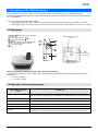
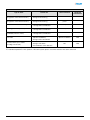
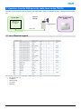
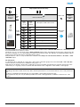
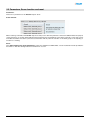
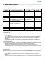
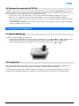
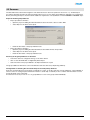
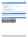
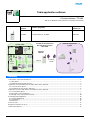
Tebis application software
LS alarm interface / TP KNX
Electrical / Mechanical characteristics: see product user manual
Product
reference
Product designation
Application
software ref.
TRC120C
LS alarm interface / TP KNX
STRC120
domovea
IP
Radio or mixed alarm
system
Location of the interface in
the radio alarm system /
Tebis KNX
System Tebis
Web
Interface
TRC120
TwinBand
RADIO
KNX bus
Media
coupler
R
Touch screen
KNX
Summary
1. Description of the TRC120 interface................................................................................................................................. 2
1.1 Description................................................................................................................................................................... 2
1.2 Reminder: Alarm system glossary............................................................................................................................... 2
2. Operation: from the KNX bus to the radio alarm via the TRC120..................................................................................... 4
2.1 List of Receiver objects ............................................................................................................................................... 4
2.2 Parameters, Scene function and reset ........................................................................................................................ 6
3. Operation: from the radio alarm to the KNX bus via the TRC120..................................................................................... 7
3.1 List of Emitter objects .................................................................................................................................................. 7
3.2 Description of the parameters ..................................................................................................................................... 8
3.3 Storage of the scene by the TRC120 ........................................................................................................................ 10
4. Learning and Configuration............................................................................................................................................. 10
4.1 Physical addressing................................................................................................................................................... 10
4.2 Configuration ............................................................................................................................................................. 10
4.3 Domovea ................................................................................................................................................................... 11
5. Factory reset ................................................................................................................................................................... 12
6. Behaviour if the bus is cut off.......................................................................................................................................... 12
7. Main characteristics ........................................................................................................................................................ 12
TRC120C
1
6T 8079-02a
1. Description of the TRC120 interface
The TRC120 interface is used to enable an intrusion alarm system from the LS range (radio or mixed central unit) to
communicate with the KNX world. On the alarm side, the interface communicates with the alarm central unit by radio and by TP
bus on the KNX side.
It acts as an input/output product which includes:
• 8 KNX outputs, these are KNX commands received by interface which are then transmitted to the alarm central unit,
• 16 KNX inputs, this is alarm system status information sent from the central unit, to which KNX controls can be associated.
1.1 Description
1
2
3
4
5
6
7
traffic TP KNX LED (twisted part), signalling
indicator red
Programming pushbutton OK
Programming pushbutton
Antenna
traffic RF LED radio alarm TwinBand (radio
frequency), signalling indicator green
2 x 8 segment display
Hatch
EIB / KNX bus connection
terminal
R
All the
necessary for
attachment
Cable gland location
How can we distinguish between the inputs and outputs on the TRC120 ?
To distinguish the 16 inputs from the 8 outputs on the TRC120, the product display indicates the numbers respectively in the
following way:
• 1 to 16 for the inputs
• 1° to 8° for the outputs
1.2 Reminder: Alarm system glossary
Radio alarm controls or
events
Central unit
Group X On / Off
• Switching on or off of group X
• Each control acts on the group concerned without modifying the status of the other groups
Partially on 1
Start-up of group 1 only, the other groups switch off
Fully on
Start-up of all the groups
Fully off
All the groups are switched off
Exit open
Management of the status of exits remaining open
Anomaly
• Storage of voltage, self protection, cut telephone line, radio connection anomaly
• Re-emission of system anomaly by the central unit whatever the status of the system
TRC120C
2
6T 8079-02a
System reactions
Type of alarm
Central unit
Siren alarm bell
Telephone
transmission
Low pre-alarm
(Progression of the intrusion level 1)
• 5 s audible beeps
• Storage in the event log
Low level
NO
Loud pre-alarm
(Progression of the intrusion level 2)
• 15 s alarm bell
• Storage in the event log
Low level or maximum
power
NO
Intrusion or intrusion confirmed (*)
• Maximum power alarm bell
• Storage and vocal indication
Maximum power
YES
Warning (Individual protection)
• Maximum power alarm bell
• Storage and vocal indication
Maximum power
YES
Silent warning
(Individual protection, Panic)
• No alarm bell
• Storage and vocal indication
NO
YES
Fire alarm
• Maximum power alarm bell for 5 min
(Specific modulation)
• Storage and vocal indication
Specific modulation
YES
Technical alarm (Frost, Mains,
Flooding, Freeze fault)
• No alarm bell
• Storage of the alarm
• Voice indication of the detection
NO
YES
(*) Intrusion confirmed = (Pre-alamr + Intrusion) or 2 consecutive intrusions
For a detailed explaination of the operation of the alarm system, please consult the manual for the alarm central unit.
TRC120C
3
6T 8079-02a
2. Operation: from the KNX bus to the radio alarm via the TRC120
In the direction Bus to alarm system, the interface can receive KNX controls to re-emit them by radio to the intrusion alarm central
unit.
System Tebis
Interface
TRC120
Radio or mixed alarm
system
KNX and / or
domovea input
modules
RADIO CONTROL
KNX TP bus
2.1 List of Receiver objects
The following controls can be emitted by a KNX emitter to the alarm system via the TRC120 interface:
• On / Off group 1 to 4
• Partially on
• Silent warning
• Fire alarm
• Warning
TRC120C
4
6T 8079-02a
Input
KNX and
domovea
modules
Output (KNX command receiver)
TP
KNX
bus
Alarm radio
Interface TRC120
KNX
outputs
1 to 8
Alarm
output
functions
Alarm
CENTRAL
UNIT
Description: Radio alarm control
Group 1 On / Off
Media
coupler
Linking
KNX
Group 2 On / Off
Group 3 On / Off
Radio alarm
control
Group 4 On / Off
Partially on 1
Silent warning (24 h / 24)
Fire alarm (24 h / 24)
Warning (24 h / 24)
The objects listed above behave like KNX command receivers (Outputs KNX). A Receiver ON / OFF and / or Scene Object can
be associated with each of these 8 controls.
The group 1 to 4 on / off controls also have a Status indication emitter object. This indicates the real status of the group on the
bus even if switching on or off is performed by an emitter from the alarm system. This indication is emitted immediately, without
waiting for the alarm system input or output time delay to elapse.
Delayed emission of the on / off by the TRC120 is available on the Group 1 to 4 on off status emitters or On status or Total
shut-down objects.
On and fully off
To obtain the Fully on and Fully off controls (On or Off of all the central unit groups) the secure emitter (On or Off or On / Off
function) must be connected to the 4 entitled On / Off group 1 to 4.
With domovea, the default controls Fully on and Fully off are proposed which automatically associate the active groups of the
central unit (2, 3 or 4 groups). Please consult the TRC120 manual for the configuration of the number of active groups.
RECOMMENDATION
Switching off the alarm central unit from any device must be performed in a secure manner with an access code, password or
key.
Products are installed and used under the sole responsibility of the installer and end customer.
The manufacturer may in no way be held responsible in the event of damage linked to fraudulant or malicious use of the
product.
TRC120C
5
6T 8079-02a
2.2 Parameters, Scene function and reset
Parameters:
There are no parameters for the Receiver objects above.
Scene function:
When receiving commands, all the Scène objects are always set to ON. This parameter cannot be modified in ETS. The purpose
of this restriction is to avoid an alarm indication being stopped or the total shutdown of the alarm sysetm by a scene type control.
In the direction KNX to the alarm system, the Scene function will only allow the activation of the alarm groups or the reporting of
an alarm or a warning.
Reset:
If the Silent warning, Fire alarm and Warning controls are emitted from aKNX emitter, a reset mechanism must be provided for
the emitter so that the following indications are taken into account.
TRC120C
6
6T 8079-02a
3. Operation: from the radio alarm to the KNX bus via the TRC120
In the direction alarm system to KNX bus, the interface can receive up to 16 statuses or alarm events transmitted by the alarm
central unit. It is possible to associate KNX controls with these events to trigger a reaction on domovea or in the KNX installation:
lighting, blinds or shutters, heating controls...
The interface plays the role alarm event receiver and behaves as an input product (command emmitter) on the KNX side.
Interface
TRC120
Radio or mixed alarm
system
System Tebis
KNX and / or
domovea output
modules
STATUS OR
RADIO EVENT
KNX TP bus
3.1 List of Emitter objects
The KNX objects corresponding to the 16 items of status information (from "Group 1 On / Off status" to "Technical alarm status")
and the associated parameters are always identical.
For each of these items of information, the associated object will be selected in the "Parameters" view from one of the following 6
functions: ON / OFF, Shutters / blinds, Heating, Priority, Scene or Timer.
Processing of the various items of information from the central unit
• Return of the system to On and Off status*:
• The alarm system is returned to on status at the end of the central unit output time delay,
• The alarm system is returned to off status at the end of the central unit input time delay,
• With domovea, it is possible to interrogate the system to find out the current status of groups 1 to 4.
• Exit open: When the system is switched on, the status of the exits is stored (deleted when the alarm system is next
switched off).
• Anomaly: When the system is switched on or off, the anomalies are stored (deleted when the alarm system is next
switched on).
• Low pre-alarm / Loud pre-alarm / Intrusion / Intrusion confirmed / Warning / Silent warning / Fire alarm / Technical
alarm: On switching off, the alarms are stored (delected when the alarm system is next switched on).
* The "on and off" statuses of the central unit can also be reported immediately if no input and / or output time delay is
programmed on the central unit.
TRC120C
7
6T 8079-02a
3.2 Description of the parameters
In the Configuration screen, it is the choice of function which will determine the type of object available (See the example below
with the Group 1 On / off status object).
Parameters
Function
Corresponding object
Value on reception of alarm event
Name
Function
Not used
Default value: Not used
ON / OFF
OFF / -, ON / -, OFF / ON, ON / OFF
Group 1 On / Off status
ON / OFF
Shutters / blinds
Up, Down, Up / Down, Down / Up
Group 1 On / Off status
Up / Down
Heating
Comfort / Night set-point, Comfort, Night setpoint, Frost protection / Auto, Frost protection,
Auto, Standby, Comfort / Standby
Group 1 On / Off status
Set point selection
Priority
Priority ON / Down / Comfort,
Priority OFF / Up / Frost protection
Group 1 On / Off status
Priority
Scene
Scene 1 to 32
Group 1 On / Off status
Scene
Timer
No duration parameters (to be adjusted on the
output)
Group 1 On / Off status
Timer
Setting parameters
■ Function ON / OFF
This function is used to switch the lighting circuit or any other load ON or OFF.
The control is sent by the ON / OFF object must be defined in the parameters.
• ON / -: Emission of the ON control upon reception of the event transmitted by the alarm central unit to the TRC120 (E.g.
start-up of group 1,
• OFF / -: Emission of the OFF control upon reception of the corresponding event, no action when the event disappears,
• OFF / ON: Emission of the OFF control upon reception of the event, ON emmission when the corresponding event
disappears,
• ON / OFF: Emission of the ON control upon reception of the event, emission of OFF when the corresponding event
disappears.
■ Shutter / blinds functions
This function controls shutters and blinds. The command to be sent by the Up / Down object must be defined in the parameters.
• Up: Emission of the Up control upon reception of the event, no action when the event disappears,
• Down: Emission of the Down command upon reception of the event, no action when the event disappears,
• Up / Down: Emission of the Up control upon reception of the event, emission of the Down control when the corresponding
event disappears,
• Down / Up: Emission of the Down control upon reception of the event, emission of the Up control when the corresponding
event disappears.
■ Heating function
This function is used select a heating setpoint. The setpoint to be sent by the Setpoint selection object must be defined in the
parameters.
• Comfort / Night set-point: Emission of the Comfort object upon reception of the event, emission of Reduced when the
corresponding event disappears,
• Comfort: Emission of the Comfort setpoint upon reception of the corresponding event, no action when the event
disappears,
• Night set-point: Emission of the Reduced setpoint upon reception of the corresponding event, no action when the event
TRC120C
8
6T 8079-02a
•
•
•
•
•
disappears,
Frost protection / Auto: Emission of the Frost protection setpoint upon reception of the event, emission of Auto when the
corresponding event disappears,
Frost protection: Emission of the Frost protection setpoint upon reception of the corresponding event, no action when the
event disappears,
Auto: Emission of the Auto setpoint upon reception of the corresponding event, no action when the event disappears,
Standby: Emission of the Economy setpoint upon reception of the corresponding event, no action when the event
disappears,
Comfort / Standby: Emission of the Comfort setpoint upon reception of the event, emission of Economy when the
corresponding event disappears,
■ Priority function
This function sends priority-start or priority-stop commands. No other command is taken into account if a priority is active. Only
end of priority or alarm commands will be taken into consideration.
The priority action depends on the type of appplication controlled: lighting, rolling shutters, heating. The priority control to be sent
by the Priority object must be defined in the parameters.
• Priority ON / Down / Comfort: Emission of Priority On - Down - Comfort upon reception of the corresponding event,
cancelling of this priority when the event disappears,
• Priority OFF / Up / Frost protection: Emission of priority OFF - Up - Frost protection upon reception of the corresponding
event, cancellation of this priority when the event disappears.
■ Timer function
This function operates like a staircase light function. The commands are sent by object Timer. The timer duration is set on the
output module.
• Timer: Emission of the timer control upon reception of the corresponding event, no action when the event disappears.
■ Scene function: Scene N° 1 to 32
The Scene function sends group controls to different kinds of outputs to create ambiences or scenarios (Panic switch, television,
etc.). The value of the Scene object is defined by the choice of the scene number.
• Scene N° x: Emission of the scene N° x upon reception of the corresonding event, no action when the event disappears.
TRC120C
9
6T 8079-02a
3.3 Storage of the scene by the TRC120
Configuration of the scenes can only be done after downloading the links between the TRC120 Scene emitter object and the
outputs controlled by the scene. The procedure which follows is used to teach the outputs concerned by the scene the statuses to
be restored as soon as the corresponding scene is activated by the TRC120.
• Use the local controls to place the outputs concerned in the desired status (lighting on, lighting off, up, down, etc.),
• Enter the scene configuration menu by pressing and holding the "+" key of the TRC120 until "Sc" is displayed,
• Short successive presses on the "+" and "-" keys are used to search for and select the input number which activates the
scene in question,
• Pressing and holding the OK key for (5 s) leads to the scene being stored. The gateway confirms storage by causing "Sc"
to flash on its display for a few seconds.
4. Learning and Configuration
4.1 Physical addressing
Procedure for physical addressing of the TRC120:
• Enter the physical addressing mode: Give a short press simultaneously on the
and
keys ➜ "Ad" is displayed on the
TRC120. The product remains in programming mode until the physical address has been transmitted by ETS,
• Exit the physical addressing mode manually: Give a short press simultaneously on the
and
keys.
4.2 Configuration
On the KNX side, the TRC120 interface is a TP product remotely supplied by the KNX bus. Addressing, configuration and
creation of links between the various KNX products is performed in accordance with the KNX standard.
To allow dialogue between the alarm central unit and the TRC120 interface, the TRC120 must be learnt by the central unit
(consult the TRC120 installation guide). ETS configuration of the TRC120 can be carried out before or after this learning.
TRC120C
10
6T 8079-02a
4.3 Domovea
The TRC120 interface allows the integration of the alarm functions in domovea (domovea version 2.5 or >). An ETS export
procedure followed by an import in domovea will allow domovea to recover all the group addresses required for its configuration.
Before performing the export, check that all the addresses required are correctly linked to a TRC120 Emitter or Receiver object.
Export of the ETS group addresses
• Export procedure from ETS 3
• Open the project including the TRC120 and then select: File menu / Save as CSV / XML
• Select Export to the OPC server export
•
• Name the file: Name of the project.esf and save
Export procedure from ETS 4
• Open the project including the TRC120 and then select Menu: Extras / Export OPC
• Select Export to the OPC server export
• Name the file: Name of the project.esf and save
Recovery of the group addresses in domovea
• Launch the domovea configurator then go to the menu: device
• Click on: See the KNX data / Configured by ETS / import
• Select the name of the project.esf file to be imported and click on open
The group addresses with names can now be linked to domovea devices by simple drag and drop.
Configuration of switching the central unit Fully On and Fully Off by domovea
Domovea automatically proposes the Fully on and Fully off control. To do this, domovea uses the addresses of the individual on
and off controls for each group and emits them in bursts to obtain fully on and fully off in accordance with the number of active
groups declared on the central unit.
It is therefore necessary to have an on / off group address for each of the groups taken individually.
TRC120C
11
6T 8079-02a
5. Factory reset
This function enables the device to be returned to its initial configuration (configuration when it came out of the factory). After a
device reset, the device can be re-used in a new installation.
•
•
Factory reset on the product
Simultaneously press for more than 5 s on the
and
Factory reset by ETS
Factory reset corresponds to the function
• Unload in ETS 3
• Unload the application and address in ETS 4
keys until "FA" is appears on the display
Factory reset causes the the product configuration to be completely deleted:
• Deletion of the physical address and links made
• Deletion of the address of the alarm central unit
After a TRC120 factory reset, the TRC120 needs to be recognised again by the alarm central unit (learning procedure).
6. Behaviour if the bus is cut off
The TRC120 interface does not operate while the bus is cut off. When the power returns to the bus, the interface requests a
system status from the alarm central unit. After receiving this data, the TRC120 checks the statuses and re-emits on the bus
those which have changed in comparison to the values saved before the outage (no parameters specifying behaviour when the
bus is cut off and restored).
7. Main characteristics
Product
TRC120
Max. number of group addresses
254
Max. number of links
255
Parameters
32
Objects
84
TRC120C
12
6T 8079-02a
TRC120C
13
6T 8079-02a