1
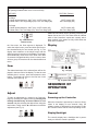
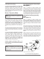
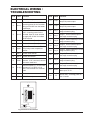
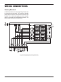
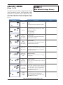
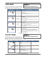
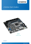
INSTALLATION & OPERATING
INSTRUCTIONS
2 & 4-Stage Temperature Controllers
For Raytherm™ & Hi Delta™
Boilers & Water Heaters
Catalog No. 5000.66D
Effective: 10-11-10
Replaces: 05-23-08
P/N 241177 Rev. 5
Rev. 5 is a completely new edition of this manual. Please discard any previous revisions.
2
CONTENTS
Sequence of Operation......................................4
of applications. They can also provide sequencing with
lead/lag on two boilers. The Controllers may be used
to provide a setpoint temperature, outdoor reset with
reset override, or dedicated domestic hot water (DHW)
generation and several options for external heater
control. An additional relay contact is included with the
“shipped loose” version to provide an alarm signal in
case of a sensor failure.
Installation ......................................................... 14
When shipped loose, this package includes:
Troubleshooting................................................. 15
(1)
(3)
(1)
(1)
Introduction........................................................ 3
User Interface..................................................... 3
Electrical Wiring / Troubleshooting..................17
Wiring Connections .......................................... 18
Controller in enclosure
Water sensors
Outdoor air sensor (optional)
Well Assembly
Controller Settings.............................................19
Technical Data ................................................... 35
Well Assembly
Quick Start Set-Up & Programming Tips.........35
Water Sensor
NOTE: Minimum 18 AWG, 105°C, stranded wire
must be used for all low voltage (less than 30 volts)
external connections to the unit. Solid conductors
should not be used because they can cause
excessive tension on contact points. Install conduit
as appropriate. All high voltage wires must be the
same size (105°C, stranded wire) as the ones on the
unit or larger.
Controller in
Enclosure
Optional Outdoor
Air Sensor
Fig. 2: Temp-Tracker Controller Kit (shipped loose)
INTRODUCTION
USER INTERFACE
The Temp-Tracker 2-stage and 4-stage temperature
controllers (Controller) are designed to be mounted on
heaters with two or four stages of operation in order to
provide accurate water temperature control in a variety
The Controller uses a Liquid Crystal Display (LCD) as
a method of supplying information. Use the LCD to
setup and monitor the operation of your system. The
Controller uses three push buttons (Item, ▲, ▼) for
selecting and adjusting the settings (see Fig. 3). As
you program your Controller, record your settings in
the actual settings columns of the Adjust menu in
tables G & H, found on pages 20 & 21.
Fig. 3: Controller Push Buttons
Menu
All of the items displayed by the Controller are organized into two menus. These menus are listed on the
upper right-hand side of the display (Menu Field). The
default menu for Controller is the View menu. While in
Fig. 1: Temp-Tracker Controller
3
DIP Switch Settings
(DIP package located under cover on front of PCB)
FACTORY (Default)
SWITCHES
Two-Stage
(A) Heater Outlet Maximum: 200ºF (On) / 235ºF Heater (Off)
(B) Heater Plant: Two Single-Stage (On) / One Two-Stage (Off)
235ºF Heater (Off)
One Two-Stage (Off)
Four-Stage
(A) Heater Outlet Maximum: 200ºF (On) / 235ºF Heater (Off)
(B) Heater Plant: Two Two-Stage (On) / One Four-Stage (Off)
235ºF Heater (Off)
One Four-Stage (Off)
B
A
Additional information can be gained by observing the
Status field of the LCD. The status field will indicate
which of the Controller’s outputs are currently active.
Most symbols in the status are only visible when the
View menu is selected.
OFF
OFF
Fig. 4: DIP Switches
(Default shown)
Display
the View menu, the View segment is displayed. To
select the Adjust menu, press and hold all three buttons simultaneously for one second (see Fig. 3). The
display then advances to the Adjust menu and the
Adjust segment is turned on in the display. The display
will automatically revert back to the View menu after
20 seconds of keypad inactivity. Once in a menu, there
will be a group of items that can be viewed within that
menu.
Item
Fig. 7: Display
The abbreviated name of the selected item will be displayed in the item field of the display. To view the next
available item in a menu, press and release the Item
button. The display will return to the first item in the
selected menu (see Fig. 5).
Fig. 8: Symbol Description
SEqUENCE OF
OPERATION
Fig. 5: Item Button
Adjust
General
To make an adjustment to a setting in the Controller,
begin by selecting the Adjust menu by pressing and
holding simultaneously all three buttons for one
second, and then selecting the desired item using the
Item button. Finally, use the ▲ or ▼ button to make the
adjustment (see Fig. 6).
Powering up the Controller
When the Controller is powered up, it turns on all segments in the display for two seconds. Next, the
software version is displayed for two seconds. Finally,
the Controller enters into the normal operating mode.
Display Backlight
Fig. 6: Adjust Buttons
The control’s display has a backlight that is permanently on while the control is powered.
4
Primary/Secondary Piping
Two Setpoints Operation, Primary Piping
Mode 1 (MODE = 1)
(Not Supported)
In primary/secondary applications, the heater outlet
temperature is typically higher than the system loop
temperature. Therefore, the Controller uses an additional sensor (called the system sensor) to measure
the temperature in the system. The operating sensor in
primary / secondary piping applications is the system
sensor. See Fig. 9.
Mode 1 is designed for setpoint operation using
Primary Piping. Once a Call for Heat (CFH) is present,
the control stages the heater to maintain the heater
target 1 at the heater outlet sensor. Once an indirect
DHW override is present, the control stages the heater
to maintain the heater target 2 at the heater outlet sensor. If both demands are present at the same time, the
control operates at the higher of the two targets.
Modes of Operation (Mode)
NOTE: Mode of operation MUST be programmed
into the Controller. See Figs. 21 through 25 on the
following pages.
Two Setpoints with Primary/Secondary
Piping
Mode 2 (Mode = 2)
Mode 2 is designed for setpoint operation using
Primary/Secondary piping (see Fig. 9). A CFH is available to activate a setpoint for space heating. An
indirect DHW override is available to activate a second
setpoint for heating an indirect domestic hot water
tank.
The Controller allows for eight modes of operation in
order to define the Controller operation and piping
arrangement used. The piping arrangement can be
categorized into primary or primary/secondary. The
mode of operation is selected using the MODE item in
the adjust menu. The operating sensor measures the
temperature being controlled out to the heating system.
Once a CFH is present, the control stages the heater
to maintain the heater target 1 at the heater supply
sensor. Once an indirect DHW override is present, the
control stages the heater to maintain the heater target
2 at the heater system sensor. If both demands are
present, the control operates at the higher of the two
targets.
The piping arrangement determines which sensor the
Controller uses as the operating sensor. The operating
sensor is either the heater outlet sensor or the system
sensor.
It is up to the designer to determine the necessary
components for and the configuration of the particular
system being designed, including additional equipment, isolation relays (for loads greater than the
Controller’s specified output rating), and any safety
devices which in the judgment of the designer are
appropriate, in order to properly size, configure and
design that system and to ensure compliance with
building and safety code requirements.
Mode 2 requires the use of three water sensors. The
inlet water sensor is located in the inlet side of the
in/out header. The outlet sensor is located in the outlet
side of the in/out header. The system sensor (terminals 6 and 4) must be located as shown in Fig. 9.
OPTIONAL INTEGRAL PUMP
BOIL OUT SENSOR
Typically, Raypak recommends Mode 2 for
primary/secondary hydronics, Mode 3 for domestic hot
water and Mode 5 for primary/secondary hydronics
using outdoor reset.
ALTERNATE
SENSOR
LOCATION
4 OR MORE
STAGES
NOTE: The illustrations for each mode are only
mechanical concept drawings; they are not intended
to describe a complete system, nor any particular
system. Consult the factory for piping arrangements
not depicted here.
BOIL IN SENSOR
PUMP LOCATION
ON MODELS WITHOUT
INTEGRAL PUMP
SYSTEM
SUPPLY
MAIN
SYSTEM
PUMP
(BY OTHERS)
SYSTEM SENSOR
*
RAYPAK TEMPERATURE
CONTOLLER
SYSTEM RETURN
*MAXIMUM 4 TIMES THE PIPE DIAMETER OR 12”, WHICHEVER IS LESS.
Fig. 9: Primary/Secondary Piping (Mode 2)
5
Domestic Hot Water Operation,
Uni-Temp 80 Piping (Mode 3)
Outdoor Reset and Override Operation with
Primary/Secondary Piping
Mode 5 (Mode = 5)
Mode 3 is designed for dedicated DHW operation
using Unitemp 80 piping. The Controller operates the
heater to maintain a tank temperature at the system
sensor.
Mode 5 is designed for outdoor reset and override
operation using Primary /Secondary Piping. The CFH
is available to provide outdoor reset for hydronic heating systems. The override can be used to heat an
indirect domestic hot water tank.
Mode 3 requires the use of three water sensors. The
inlet water sensor is located in the inlet side of the
in/out header and the outlet sensor is located in the
outlet side of the in/out header. The system sensor
(terminals 6 and 4) must be located in the storage
tank, as shown in Fig. 10.
Once a CFH is present, the control stages the heater
to maintain the calculated outdoor reset target at the
heater system sensor. Once an indirect DHW override
is present, the control stages the heater to maintain
the heater target 2 at the heater system sensor. If both
demands are present at the same time, the control
operates at the higher of the two targets.
Mode 5 requires the use of three water sensors and
one air sensor. The inlet water sensor is located in the
inlet side of the in/out header. The outlet sensor is
located in the outlet side of the in/out header. The system sensor (terminals 6 and 4) must be located on the
system supply pipe, as shown in Fig. 11.
The outdoor air sensor must be located on the coldest
side of the building in a shaded area out of direct sunlight.
OPTIONAL INTEGRAL PUMP
Fig. 10: Uni-Temp 80 Piping (Mode 3)
BOIL OUT SENSOR
Outdoor Reset and Override Operation with
Primary Piping
Mode 4 (Mode = 4)
(Not Supported)
ALTERNATE
SENSOR
LOCATION
4 OR MORE
STAGES
BOIL IN SENSOR
PUMP LOCATION
ON MODELS WITHOUT
INTEGRAL PUMP
OUTDOOR
AIR
SENSOR
SYSTEM
SUPPLY
Mode 4 is designed for outdoor reset and override
operation using Primary Piping. Once a CFH is present, the control stages the heater to maintain the
calculated outdoor reset target at the heater outlet
sensor. Once an indirect DWH override is present, the
control stages the heater to maintain the heater target
2 at the heater outlet sensor. If both demands are
present at the same time, the control operates at the
higher of the two targets.
MAIN
SYSTEM
PUMP
(BY OTHERS)
SYSTEM SENSOR
*
RAYPAK TEMPERATURE
CONTOLLER
SYSTEM RETURN
*MAXIMUM 4 TIMES THE PIPE DIAMETER OR 12”, WHICHEVER IS LESS.
Fig. 11: Primary/Secondary Piping with Outdoor Reset
(Mode 5)
6
External Target Temperature Input and
Override with Primary Piping
Mode 6 (Mode = 6)
(Not Supported)
NOTE: To convert a 0-20 mA input signal to 0-10
VDC, a 500 Ω resistor must be added. See Fig. 13.
Mode 6 is designed for a 0-10VDC or a 4-20 mA external input signal and override operation using Primary
Piping. The external input signal creates an internal
CFH and changes the heater target according to a linear scale. The control stages the heater to maintain
the heater target at the heater outlet sensor.
External Target Temperature Input and
Override with Primary/Secondary Piping
Mode 7 (Mode = 7)
500 Ω
GND
HOT
0-20
mA INPUT
Mode 7 is designed for a 0-10VDC external input signal and override operation using Primary/Secondary
Piping. The external input signal can be provided from
a Building Management System. The override can be
used to heat an indirect domestic hot water tank.
500 Ω
GND
HOT
0-20
mA INPUT
Fig. 13: 500 Ω Resistor for 4-20 mA Operation
External Direct Drive Operation
Mode 8 (Mode = 8)
The external input signal creates an internal CFH and
changes the heater target according to a linear scale.
The control stages the heater to maintain the heater
target at the heater outlet sensor.
Mode 8 is designed for a 0-10VDC or a 4-20 mA external input signal from a building management system or
external sequence, such as the Raypak TempTracker Mod+ Hybrid, to drive the staging rate
directly with either Primary or Primary/Secondary piping. The indirect DHW override is disabled.
Once an indirect DHW override is present, the control
stages the heater to maintain the heater target at the
heater system sensor. If both an external input signal
and an indirect DHW override are present at the same
time, the control operates at the higher of the two targets.
The control receives a CFH and analog signal provided from an external control. The control stages the
heater according to the input signal. The maximum
outlet temperature is controlled by DIP switch “A.”
Fixed Heater Outlet Maximum: 200°F (“A” = “ON”)
235°F (“A” = “OFF”)
Fig. 12: External Input Target Temperature and Setpoint
Operation, Primary-Secondary Piping (Mode 7)
Fig. 14: External Direct Drive Operation (Mode 8)
7
Code Descriptions
Heater Differential (DIFF)
A heat source must be operated with a differential in
order to prevent short cycling. The heater differential is
divided around the heater target temperature. The
first-stage contact will close when the water temperature at the operating sensor is 1/2 of the differential
setting below the heater target temperature, and will
open when the water temperature at the operating
sensor is 1/2 of the differential setting above the
heater target temperature. The remaining stages will
operate sequentially based on the staging mode
selected.
Fig. 16: Auto Differential
Staging Mode (STGMODE)
Manual Differential
The Controller can operate up to four stages in order
to supply the required target temperature. The method
of staging used by the Controller is either P (proportional) or PID (proportional, integral & derivative), and
is selected using the STGMODE item in the adjust
menu.
The differential can be manually set using the DIFF
setting in the Adjust menu.
Proportional (P)
Proportional staging is based on manually-adjusted
settings that determine when the next stage is
required to turn on. These manual settings are based
on temperature and time. The interstage differential
sets the temperature drop at which the next stage
turns on. However, in order for a stage to fire, both the
“interstage delay on” and “minimum off” times must
first elapse.
Fig. 15: Fixed Differential
Auto Differential
Auto Differential is only available when using PID staging.
If Auto Differential is selected, the control automatically determines the best differential as the load changes,
thereby improving efficiency. During light loads, the differential is increased to allow longer on and off times
to reduce the potential for short-cycling. During large
loads, the differential is narrowed thereby improving
comfort in heating spaces by reducing temperature
swing.
Fig. 17: Proportional Staging
8
Interstage Differential (STG DIFF)
Proportional, Integral & Derivative
(PID)
The “interstage differential” is the temperature drop at
which the next stage will turn on. Once a stage turns
on, the next stage cannot turn on until the temperature
drops the “interstage differential” below the temperature at which the previous stage turned on. The
“interstage differential” is adjustable through the STG
DIFF setting in the adjust menu.
PID staging allows the Controller to determine when
the next stage is required to turn on or off. The
Controller automatically determines the settings that
are manually selected in the proportional mode.
After each stage is turned on in the firing sequence,
the Controller waits a minimum amount of time before
turning on the next stage. After the minimum time
delay between stages has passed, the Controller
examines the control error to determine when the next
stage is to fire. The control error is determined using
PID logic.
Interstage Delay On (ON DLY)
The “interstage delay on” is the amount of time that
must elapse before turning on the next stage. Once a
stage turns on, the next stage cannot turn on until the
interstage delay on time elapses. The interstage delay
on is adjustable through the ON DLY setting in the
adjust menu.
Proportional compares the actual operating sensor
temperature to the heater target temperature. The
colder the temperature, the sooner the next stage is
turned on.
Interstage Delay Off (OFF DLY)
Integral compares the operating sensor temperature
offset (error) to the heater target temperature over a
period of time.
The “interstage delay off” is the amount of time that
must elapse before turning off the next stage. Once a
stage turns off, the next stage cannot turn off until the
interstage delay off time elapses. The interstage delay
off is adjustable through the OFF DLY setting in the
adjust menu.
Derivative determines how fast or slow the operating
sensor temperature is changing. If the temperature is
increasing slowly, the next stage is turned sooner. If
the temperature is increasing quickly, the next stage is
turned on later, if at all.
Minimum On Time (MIN ON)
The “minimum on” time is the minimum amount of time
that a stage must be on before it is allowed to turn off.
Once a stage turns on, the next stage cannot turn off
until minimum on time elapses. The minimum on time
is adjustable through the MIN ON setting in the Adjust
menu.
Heater Mass (BOIL MASS)
The heater mass setting (1, 2 or 3) allows the installer
to adjust the Controller to the thermal mass of different
types of heat sources used. The heater mass setting
automatically determines the interstage differential,
interstage delay on, interstage delay off, minimum on
time and minimum off time of the stages when PID
staging is used. A higher thermal mass setting provides slower staging, while a lower thermal mass
provides faster staging.
Minimum Off Time (MIN OFF)
The “minimum off” time is the minimum amount of time
that a stage must be off before it is allowed to turn on.
Once a stage turns off, it cannot turn on until minimum
off time elapses. The minimum off time is adjustable
through the MIN OFF setting in the adjust menu.
Heater Mass Definitions
Mass 1
Low Volume, High Recovery
Mass 2
Medium Volume, Medium Recovery
Mass 3
High Volume Low Recovery
Table A: Heater Mass Definitions
NOTE: Always use a heater mass setting of 1 for
Raypak equipment. If the Controller continues to
stage too rapidly, contact Raypak.
9
Heater Target Temperature (BOIL
TARGET)
The heater target temperature is determined from the
mode of operation and type of demand applied. The
Controller displays the temperature that it is currently
trying to maintain at the operating sensor as BOIL
TARGET in the view menu.
The operating sensor for modes 2, 3, 5 and 7 is the
system sensor. If the Controller is not presently
enabled for heat, it displays “- - -“ in the LCD. In Mode
8, no heater target temperature is generated.
System Pump Operation
The pump contacts operate when:
• A CFH is present based on the tank sensor for
dedicated DHW operation (Mode 3).
• While the heater is firing and Primary/Secondary
piping (Mode 2, 5, or 7) is used. Primary/
Secondary piping reduces standby losses by isolating the heater from the system while the heater
is off.
• During external direct drive operation (Mode 8),
the pump contact closes whenever there is an
internal CFH.
• After the system shuts off the pump remains on for
a few minutes to purge heat from the heater to the
system.
Fig. 18: Warm Weather Shutdown
Heater Minimum (BOIL MIN)
The BOIL MIN is the lowest water temperature that the
Controller is allowed to use as a heater target temperature (e.g. 120 ºF). During mild conditions, if the
Controller calculates a heater target temperature that
is below the BOIL MIN setting, the heater target temperature is adjusted to at least the BOIL MIN setting.
During this condition, if the heater is operating, the
MIN segment turns on in the LCD while the heater target temperature or heater operating sensor
temperature is viewed.
System Pump Purge (DLY)
The controller operates the system pump based on the
Pump DLY setting. Once the system shuts down, the
controller keeps the system pump running for the time
selected.
Additional plumbing and/or controls may be required to
maintain the heater at or above its minimum inlet temperature.
NOTE: If the installed heater is designed to operate
at a target temperature less than 80°F, set the BOIL
MIN adjustments to OFF.
When Pump DLY is set to OFF, there is no purging.
When Pump DLY is set to ON, the system pump runs
continuously. When on is selected and the control is
configured for outdoor reset, the system pump continues to run even during Warm Weather Shut Down
(Mode 5).
Heater Maximum (BOIL MAX)
The BOIL MAX is the highest water temperature that
the Controller is allowed to use as a heater target temperature. If the Controller does target BOIL MAX, and
the heater outlet sensor is near the BOIL MAX temperature, the MAX segment turns on in the LCD while the
heater target, heater inlet, heater outlet or heater supply temperature is viewed.
10
Pump Exercising
Internal DHW Demand
If the system pump has not operated at least once
every 70 hours, the control turns on the output for 10
seconds. This minimizes the possibility of the pump
seizing during a long period of inactivity.
A sensor is required to be installed in the tank and connected to the Com and the Sys/D terminals (6 and 4).
A CFH for DHW is generated when the temperature at
the DHW sensor drops 1/2 of the tank differential setting below the desired DHW tank temperature. The
TANK TARGET setting is used to set the desired DHW
tank temperature. Once a CFH is generated, the Dem
segment turns on in the LCD.
Setpoint Operation
A setpoint is a fixed water temperature target that the
heater is to maintain at the system sensor. The heater
maintains the heater target by operating the stages
using the proportional or the PID logic together with
the heater differential. The setpoint temperature is set
using the BOIL TARGET item in the adjust menu.
The Controller then operates the heater stages to
maintain the programmed heater target temperature at
the heater system sensor located in the tank. The
heater target temperature is set using the BOIL TARGET item in the adjust menu.
Mode 2 and Enable (Dem 1)
Tank Differential (TANK DIFF)
A call for heat (CFH) is required whenever heat is
required for the primary heating load. This CFH is
generated when 24VAC is applied across the
enable/disable connection P1 (terminals 1 and 2).
Once the voltage is applied, the control turns on the
Dem 1 segment in the display and the controller operates the heater stages to maintain the BOIL TARGET
1 at the system sensor.
A differential setting that operates 1/2 above and
below the TANK TARGET is selectable using the
TANK DIFF item in the adjust menu.
Outdoor Reset Operation
When Mode 5 is selected, the Controller uses outdoor
reset to control the water temperature. Outdoor reset
adjusts the target temperature based on the outdoor
air temperature and the reset ratio; as the outdoor air
temperature rises, the need for heat drops and the setpoint is reduced The reset ratio is determined from the
Heater Start, Heater Design, Outdoor Start and
Outdoor Design settings.
Mode 2, 5 and 7, and Domestic Hot
Water Override (Dem 2)
A CFH is required whenever heat is required for the
secondary heating load such as an indirect domestic
hot water tank. A CFH is generated when 24VAC is
applied across the DHW contacts P1 (terminals 1 and
3). Once the voltage is applied, the control turns on the
Dem 2 segment in the display and the controller operates the heater stages to maintain the BOIL TARGET
2 at the system sensor.
Enable/Disable
A CFH is generated when a voltage of 24 VAC is
applied across the Enable/Disable terminals (1 and 2).
Once voltage is applied, the Controller turns on the
Dem 1 segment in the display. If the Controller is not
in Warm Weather Shut Down (WWSD), it then operates the heater stages to maintain the heater target
temperature.
Dedicated Domestic Hot Water
(DHW) Operation
When mode 3 is selected, the Controller provides dedicated DHW operation.
NOTE: If the controller is in WWSD, the WWSD
segment is shown in the display and the heater target in the view menu of the display remains “ - - - “
(no target).
WARNING: Verify closure across Enable/Disable
contacts P1, terminals 1 and 2. DO NOT use DHW
override on terminal 3.
11
Reset Ratio
Heater Design (BOIL DSGN)
The controller uses the following four settings to calculate the Reset Ration (RR):
The BOIL DSGN is the water temperature required to
heat the zones when the outdoor air is as cold as the
OUTDR DSGN temperature.
RESET RATIO (RR) =
BOILER DESIGN — BOILER START
OUTDOOR START — OUTDOOR DESIGN
Warm Weather Shut Down (WWSD)
When the outdoor air temperature rises above the
WWSD setting, the Controller turns on the WWSD
segment in the display. When the Controller is in Warm
Weather Shut Down, the Dem 1 segment is displayed
if there is a heat demand. However, the Controller
does not operate the heating system to satisfy this
demand.
For example, using the Mode 5 default values, the RR
would be .56:1.
Heater Start (BOIL START)
The BOIL START temperature is the theoretical supply
water temperature that the system requires when the
outdoor air temperature equals the OUTDR START
temperature setting. The BOIL START is typically set
to the desired building temperature.
External Temperature Target
Input
When Mode 7 is selected, the controller allows for an
external control to operate the heater temperature
through an input signal generated by a Building
Management System (BMS) or Energy Management
System (EMS).
180°F
CFH
A CFH is generated when a contact closure is present
at the enable/disable connection on P1 pins 1 and 2
(or pins 1 and 3 for Indirect DHW), and an analog positive 0-10 VDC signal is applied to the +V (in) input
(terminal 10). The negative V (DC) is applied to the
Com/- input (terminal 9).
135°F
70°F
-10°F
Decreasing Outdoor Temperature
0-10 VDC or 0-20mA External Input
(Mode 7)
Fig. 19: Heater Start
Outdoor Start (OUTDR START)
When the 0-10VDC range is selected, an input voltage
of 1VDC corresponds to a heater target temperature of
50ºF (10ºC). An input voltage of 10VDC corresponds
to a heater target temperature of 210ºF (99ºC). As the
voltage varies linearly between 1VDC and 10 VDC,
the heater target temperature varies linearly between
50ºF (10ºC) and 210ºF (99ºC). If a voltage below
0.5VDC is received, the heater target temperature is
displayed as “ - - -“ indicating that there is no longer an
internal CFH.
The OUTDR START temperature is the outdoor air
temperature at which the Controller provides the BOIL
START water temperature to the system. The OUTDR
START is typically set to the desired building temperature.
Outdoor Design (OUTDR DSGN)
The OUTDR DSGN is the outdoor air temperature that
is the typical coldest temperature of the year where the
building is located. This temperature is used when
doing heat loss calculations for the building.
A 0-20 mA signal can be converted to a 0-10VDC signal by installing a 500 Ohm resistor in parallel to the
input signal on the controller’s terminals (terminals 9 &
10). See Fig. 13 on page 7.
12
0-10 VDC
0-20 mA*
Heater Target
0
0
- - - (OFF)
1
2
50ºF (10ºC)
2
4
68ºF (20ºC)
3
6
86ºF (30ºC)
4
8
103ºF (39ºC)
5
10
121ºF (49ºC)
6
12
139ºF (59ºC)
7
14
157ºF (69ºC)
8
16
174ºF (79ºC)
9
18
192ºF (89ºC)
10
20
210ºF (99ºC)
A 4-20 mA signal can be converted to a 2-10 VDC signal by installing a 500 ohm resistor in parallel to the
input signal on the controller’s terminals (terminals 9 &
10).
OFFSET
The offset setting allow the heater target temperature
to be fine tuned to the external input signal. The controller reads the external input signal and converts
this to a heater target temperature. The offset is then
added to the heater target temperature.
Example Range = 0-10 VDC
Input = 7 VDC
Offset = + 5º F (3º C)
Heater Target =
*Requires a 500 Ω resistor
External Direct Drive Operation
(Mode 8)
Table B: 0-10 VDC or 0-20mA External Input (Mode 7)
2-10 VDC or 4-20 mA External Input
Signal
When Mode 8 is selected, the controller allows for an
external control to operate the heater through an
analog direct drive input signal provided by a heater
sequencing control, such as the Raypak TempTracker Mod+ Hybrid. When in mode 8, the indirect
DHW override is disabled.
The external input signal can be selected to be either
0-10 VDC or 2-10 VDC. When the 2-10 VDC range is
selected, an input of 2 VDC corresponds to a heater
target temperature of 50ºF (10ºC). An input voltage of
10 VDC corresponds to a heater target temperature of
210º F (99º C). As the voltage varies between 2 VDC
and 10 VDC, the heater target temperature varies linearly between 50ºF (10ºC) and 210º F (99º C). If a
voltage below 1.5 VDC is received the heater target
temperature is displayed as “ - - - “ indicating that there
is no longer an internal CFH.
2-10 VDC
4-20 mA*
Heater Target
0
0
- - - (OFF)
1
2
- - - (OFF)
2
4
50ºF (10ºC)
3
6
70ºF (21ºC)
4
8
90ºF (32ºC)
5
10
110ºF (43ºC)
6
12
130ºF (54ºC)
7
14
150ºF (66ºC)
8
16
170ºF (77ºC)
9
18
190ºF (88ºC)
10
20
210ºF (99ºC)
157º F (69º C)
+ 5º F (3º C)
162º F (72º C)
Direct Drive Input Signal
An external heater sequencer provides a positive 010 VDC input signal to the controller +V input
(terminal 10). The negative VDC signal is applied to
the Com/- input (terminal 9).
The heater remains off while the direct drive input
signal is between 0.0 to 0.5 VDC. The Stage 1 contact remains on as long as the direct drive input
signal reaches or exceeds 0.5 VDC. The Stage 2
contact is activated once the direct drive input signal
reaches or exceeds 3.0 VDC. The Stage 3 contact is
activated once the direct drive input signal reaches or
exceeds 5.5 VDC. The Stage 4 contact is activated
once the direct drive input signal reaches or exceeds
8.0 VDC.
PUMP OPERATION
The pump is turned on as soon as the direct drive input
signal reaches 0.5 VDC. Once the direct drive input
signal falls below 0.5 VDC, the pump continues to
operate until the Pump DLY purge expires, then the
pump shuts off.
*Requires a 500 Ω resistor
Table C: 2-10 VDC or 4-20mA External Input (Mode 7)
13
Fig. 20: Stage Actuation and Dead Bands
BOILER OUTLET MAXIMUM
TEMPERATURE
CAUTION: The 120VAC connection must be
applied to Terminal Block P3 (pins 1 and 2). Pin 3
must be connected to Ground.
The external sequencer is able to operate the heater
temperature. However, the BOIL OUT MAX setting limits the highest temperature at the heater outlet sensor.
Should the heater outlet setting exceed the BOIL OUT
MAX setting, the stage contacts are opened to shut off
the heater. The heater remains off for the minimum off
time and the heater outlet temperature falls 2º F (1º C)
below the BOIL OUT MAX setting.
Electrical Connections to the
Controller
The installer should test to confirm that no voltage is
present at any of the wires during installation.
Powered Input Connections
NOTE: BOILER OUT MAX is set using DIP Switch
“A”: OFF = 235°F, ON = 200°F (see Fig. 4).
System Pump Contact
INSTALLATION
The Pump terminals (13 and 14 on the controller to
pins 4 and 5 on P3) are an isolated output in the controller. There is no power available on these terminals
from the controller. This output is to be used as a
switch to either make or break power to the system
pump. Since this is an isolated contact, it may switch
voltage up to 120 VAC that does not to exceed 5
amps. For larger pumps, a contactor must be used.
The following describes field installation:
For field installation, this controller is shipped inside a
water-resistant enclosure. This kit includes a built-in
transformer, an alarm relay, and three terminal blocks
(labeled P1, P2 and P3) with built-in decals describing
the various connections. See Fig. 25 for proper wiring.
14
Heater Contacts
Heater Sys/D or DHW Sensor
The Stg 1, Stg 2, Stg 3 and Stg 4 terminals (15 through
22) are isolated outputs in the Controller. There is no
power available on these terminals from the Controller.
These terminals are to be used as a switch to either
make or break the heater circuit. When the Controller
requires heater stages to fire, it closes the contact
between the appropriate terminals.
Either a System Sensor or DHW Sensor may be connected to the Controller. If a sensor is used, connect
the two wires from the sensor to the Com (common
sensor) and the Sys/D (demand/DHW sensor) terminals (4 and 6).
TROUBLESHOOTING
Alarm Contact
Field Testing the Power Supply
For field installations, terminals 19 and 20 provide dry
contacts for an alarm. For factory installations, the
alarm is installed with a UDB diagnostic control (when
available). The UDB provides the alarm dry contacts.
Verify that all exposed wires and bare terminals are
not in contact with other wires or grounded surfaces.
Turn on the power and measure the voltage between
the 1 and 2 terminals on the P3 terminal block, using
an AC voltmeter. The reading should be 120 VAC ±
10%, and the reading between terminals 2 and 3 must
be less than 1.0 VAC.
Sensor and Unpowered Input
Connections
NOTE: Do not apply power to these terminals as
this damages the Controller.
Verify the power at the transformer by using the AC
voltmeter across pins 1 and 4 of terminal block P1.
The reading should be between 22 VAC and 26 VAC.
Outdoor Sensor
CAUTION: The sensor must be disconnected in
order to measure the correct ohms.
Connect the two wires from the optional outdoor sensor to the Com (common sensor) and Air (outdoor air
sensor) terminals (4 and 5). The outdoor sensor is
used by the Controller to measure the outdoor air temperature.
Testing the Sensors (10 kΩ)
In order to test the sensors, the actual temperature at
each sensor location must be measured.
Heater Outlet Sensor (Field Install)
Using Table D on page 16, estimate the temperature
measured by the sensor, based on ohm readings from
various sensors to COM.
Connect the two wires from the Heater Outlet Sensor
to the Com (common sensor) and the Boil Out (heater
outlet sensor) terminals (4 and 7). The heater outlet
sensor is used by the Controller to measure the heater
outlet water temperature from the heater.
The sensor and thermometer readings should be
close. If the meter reads a very high resistance, there
may be a broken wire, a poor wiring connection or a
defective sensor. If the resistance is very low, the
wiring may be shorted, there may be moisture in the
sensor or the sensor may be defective. To test for a
defective sensor, measure the resistance directly at
the sensor location.
NOTE: The heater outlet sensor is required for
every mode of operation.
Heater Inlet Sensor (Field Install)
Testing the Enable/Disable and
DHW Field Install Inputs
Connect the two wires from the Heater Inlet Sensor to
the Com (common sensor) and the Boil In (heater inlet
sensor) terminals (4 and 8). The heater inlet sensor is
used by the Controller to measure the heater inlet
water temperature to the heater.
When the Enable/Disable system calls for heat, you
should measure between 22 VAC and 26 VAC at terminals 2 and 4 on P1. When the heat demand device
is off, you should measure less than 1 VAC. For DHW
override, use terminals 3 and 4.
15
5. After 13 seconds, Stage 4 is turned on.
6. After 16 seconds, the pump and stages 1 to 4 are
shut off. The alarm contacts are closed for 10 seconds.
7. The control exits the test sequence and resumes
normal operation.
Sensor Resistance
Fig. 21: Multi-meter
NOTE: Make sure ALL power to the devices and
wiring harness is off.
Connecting the Controller
Apply power to the Controller. The operation of the
Controller on power up is described in the Sequence
of Operation section, starting on page 4 of this manual.
Testing the Controller’s
Fig. 22: Testing the Controller’s Outputs
Outputs
The Controller has a built-in test routine, which is used
to test the main control functions. The test sequence is
enabled when the ▲ button is pressed and held for 3
seconds while in the View menu. The outputs are tested in the following sequence:
1. After 1 second, the pump is turned on.
2. After 4 seconds, Stage 1 is turned on.
Temperature (°°F)
Resistance (Ω)
-50
490,813
-40
336,606
-30
234,196
-20
165,180
-10
118,018
0
85,362
10
62,465
20
46,218
30
34,558
40
26,099
50
19,900
60
15,311
70
11,883
77
10,000
80
9,299
90
7,334
100
5,828
110
4,665
120
3,760
130
3,050
140
2,490
150
2,045
160
1,689
170
1,403
180
1,172
190
983
200
829
210
703
220
598
Table D: Sensor Resistance
3. After 7 seconds, Stage 2 is turned on.
4. After 10 seconds, Stage 3 is turned on.
16
ELECTRICAL WIRING /
TROUBLESHOOTING
Pin #
Label
1
CD
Function
24 VAC return power.
Pin #
Label
Function
13
Pmp
Pump Contact – Not to exceed 5
amps. No power output.
14
Pmp
Pump Contact – Not to exceed 5
amps. No power output.
Dem 1
Enable/Disable - Hot 24 VAC Incoming power for the Controller.
Bring hot 24 VAC from the heater
transformer.
15
Stg 1
Stage 1, Odd-numbered pin on the
stage connection plug
3
Dem 2
Indirect DHW Override – Hot 24
VAC – Incoming power for the
demand. Open or close contacts
to supply hot 24 VAC for indirect
DHW override.
16
Stg 1
Stage 1, Even-numbered pin on
the stage connection plug
4
Com
Outdoor Sensor (if used)
17
Stg 2
Stage 2, Odd-numbered pin on the
stage connection plug
5
Out
Outdoor Sensor (if used)
Stg 2
Stage 2, Even-numbered pin on
the stage connection plug
6
Sys/D
System/Demand Sensor - This is
the primary water temperature
sensor.
18
19
Stg 3
Stage 3, Odd-numbered pin on the
stage connection plug
7
Boil O
Heater Outlet Sensor
8
Boil In
Heater Inlet Sensor
20
Stg 3
Stage 3, Even-numbered pin on
the stage connection plug
9
COM/-
Common return lead for all of the
sensors. If all 3 are used, connect
the return leads here.
21
Stg 4
Stage 4, Odd-numbered pin on the
stage connection plug
22
Stg 4
Stage 4, Even-numbered pin on
the stage connection plug
+V (in)
Used for modes 6, 7 or 8 for external input of 0-10 VDC or 2-10
VDC. Use terminal 9 for common
lead.
23
Alarm
Alarm notification circuit - may
draw up to 72 VA
24
R
2
10
11
12
Not used
C
24 VAC return power
Table E: Control Pin-outs
24 R
12 C
23 Alarm
11
10 +V(in) 22 Stg 4
9 Com/- 21 Stg 4
8 Boil in 20 Stg 3
7 Boil O 19 Stg 3
6 Sys/D 18 Stg 2
5 Out 17 Stg 2
4 Com 16 Stg 1
3 Dem 2 15 Stg 1
2 Dem 1 14 Pmp
13 Pmp
1 CD
B
A
OFF
OFF
Fig. 23: Electrical Connections
17
Hot 24 VAC - Incoming power to
the Controller
WIRING CONNECTIONS
Factory-Mounted
On Hi Delta heaters, the multi-stage Temp Tracker can
be ordered factory-mounted. The controller is already
powerd by the heater, the inlet and outlet sensors are
installed in the inlet/outlet header, and the controller
alarm is connected to the UDB diagnostic board. The
heater stage connections are also wired.
TO
UDB
P4
Fig. 24: Wiring Diagram (Factory Mounted)
18
CONTROLLER
SETTINGS
Field Installation
Field wiring must be connected to the terminal block
on the back side of the controller mounting bracket.
Follow the wiring diagram as specified in Fig. 25
below.
Tables F through T describe the “View” and “Adjust”
menus. They also show the default settings as well
as any possible adjustment ranges.
120V
Fig. 25: Wiring Diagram (Field Installation)
19
VIEW MENU
MODE 2
(With Default Settings Shown)
The View menu items display current operating temperatures and system status information. Use the
Item button (see Fig. 5) to view items in this menu.
Item Field
Range
Description
---,
35 to 266°F
(2 to 130°C),
OFF
BOILER TARGET
The boiler target is the temperature the control is
currently trying to maintain at the boiler supply sensor
or the boiler outlet sensor.
-20 to 266°F
(-29 to 130°C)
-20 to 266°F
(-29 to 130°C)
-20 to 266°F
(-29 to 130°C)
0 to 252°F
(0 to 140°C)
0 to 999
BOILER SUPPLY
Current boiler supply water temperature as measured
by the boiler supply sensor.
Note: This item is only available when MODE is set to 2.
BOILER OUTLET
Current boiler outlet water temperature as measured
by the boiler outlet sensor.
Note: When MODE is set to 2 this item is only visible
in the Factory access level.
BOILER INLET
Current boiler inlet water temperature as measured by
the boiler inlet sensor.
Note: This item is only available when a boiler inlet
sensor is installed.
BOILER DELTA T
Current temperature difference between the boiler outlet
sensor and the boiler inlet sensor.
Note: This item is only available when a boiler inlet
sensor is installed.
BOILER ON HOURS
The total number of running hours of the boiler since
this item was last cleared. Clear the numbers of hours
by pressing and holding the and buttons together
while viewing this item.
Table F: View Menu, Mode 2
20
ADJUST MENU
MODE 2
(Page 1 of 2)
(With Default Settings Shown)
The Adjust menu items are the programmable settings
used to operate the system. Press and hold all three
buttons for one second to enter the Adjust menu, then
select the desired item using the Item button. Finally,
use the ▲ or ▼ button to make the adjustment (see
Fig. 6).
Item Field
Range
Description
1 to 8
MODE
Select the operating mode for the control.
PId or P
STAGE MODE
Select the staging operation to be either
automatic or manual.
(PId = automatic)
(P = proportional)
OFF,
70 to 230°F
(21 to 110°C)
BOILER TARGET 1
Select the boiler target temperature while a
heat demand is present.
OFF,
70 to 230°F
(21 to 110°C)
BOILER TARGET 2
Select the boiler target temperature while a
setpoint demand is present.
120 to 235°F
(49 to 113°C)
BOILER OUTLET MAXIMUM
S e l e c t th e m a x i m u m b o i l e r o u t l et
temperature. Exceeding this temperature
shuts off the burners.
120 to 235°F
(49 to 113°C),
OFF
BOILER MAXIMUM
Select the maximum boiler target
temperature.
OFF,
80 to 180°F
(27 to 82°C)
BOILER MINIMUM
S e l e c t th e m i n i m u m b o i l e r t a r g et
temperature.
0:00 to 3:00 min
(1 second
increments)
1 (Lo) or
2 (Med) or
3 (Hi)
FIRE DELAY
Select the amount of time required
for combustion pre-purging, ignition
a n d t h e fl a m e to b e e s t a b l i s h e d .
Note: This setting is only available when
STAGE MODE is set to PId.
BOILER MASS
Select the thermal mass of the boiler.
Note: This setting is only available when
STAGE MODE is set to PId.
Table G: Adjust Menu, Mode 2 (page 1 of 2)
21
Setting
ADJUST MENU
MODE 2
(Page 2 of 2)
Item Field
(With Default Settings Shown)
Range
Description
Au, 0:30 to
9:55 min
STAGE DELAY
Select the minimum time delay between
stages.
Note: This setting is only available when
STAGE MODE is set to PId.
Au, 2 to 42°F
(1 to 23°C)
DIFFERENTIAL
Select the boiler differential.
Note: The automatic setting is only available
when STAGE MODE is set to PId staging.
OFF, 0:20 to
9:55 min, On
°F or °C
0 to 10°F
(0 to 6°C)
0:10 to 8:00 min
PUMP DELAY
Select the system pump purge time after
shutting off the burner.
TEMPERATURE UNITS
Select to display temperature in degrees
Fahrenheit or in degrees Celsius.
STAGE DIFFERENTIAL
Select the interstage temperature differential
between stages for proportional staging.
Note: This setting is only available when
STAGE MODE is set to P.
INTERSTAGE ON DELAY
Select the amount of time that must pass
once a stage has been turned on in order
to allow the next stage to turn on.
Note: This setting is only available when
STAGE MODE is set to P.
0:10 to 4:00 min
INTERSTAGE OFF DELAY
Select the amount of time that must pass
once a stage has been turned off in order
to allow the next stage to turn off.
Note: This setting is only available when
STAGE MODE is set to P.
0:10 to 5:00 min
MINIMUM ON TIME
Select the minimum amount of time that
the stage contact must remain on before it
is allowed to turn off.
Note: This setting is only available when
STAGE MODE is set to P.
0:10 to 5:00 min
MINIMUM OFF TIME
Select the minimum amount of time that
the stage contact must remain off before it
is allowed to turn back on.
Note: This setting is only available when
STAGE MODE is set to P.
Table H: Adjust Menu, Mode 2 (page 2 of 2)
22
Setting
VIEW MENU
MODE 3
(With Default Settings Shown)
The View menu items display current operating temperatures and system status information. Use the
Item button (see Fig. 5) to view items in this menu.
Item Field
Range
Description
---,
35 to 266°F
(2 to 130°C),
OFF
TANK TARGET
The temperature that the control is trying to maintain
in the tank.
-20 to 266°F
BOILER OUTLET
Current boiler outlet water temperature as measured
by the boiler outlet sensor.
(-29 to 130°C)
-20 to 266°F
(-29 to 130°C)
0 to 252°F
(0 to 140°C)
-20 to 266°F
(-29 to 130°C)
0 to 999
BOILER INLET
Current boiler inlet water temperature as measured by
the boiler inlet sensor.
Note: This item is only available when a boiler inlet
sensor is installed.
BOILER DELTA T
Current temperature difference between the boiler outlet
sensor and the boiler inlet sensor.
Note: This item is only available when a boiler inlet
sensor is installed.
TANK
Current domestic hot water tank temperature as measured
by the DHW tank sensor.
BOILER ON HOURS
The total number of running hours of the boiler since
this item was last cleared. Clear the numbers of hours
by pressing and holding the and buttons together
while viewing this item.
Table I: View Menu, Mode 3
23
ADJUST MENU
MODE 3
(Page 1 of 2)
(With Default Settings Shown)
The Adjust menu items are the programmable settings
used to operate the system. Press and hold all three
buttons for one second to enter the Adjust menu, then
select the desired item using the Item button. Finally,
use the ▲ or ▼ button to make the adjustment (see
Fig. 6).
Item Field
Range
Description
1 to 8
MODE
Select the operating mode for the control.
PId or P
STAGE MODE
Select the staging operation to be either
automatic or manual.
(PId = automatic)
(P = proportional)
OFF, 70 to
190°F
(21 to 88°C)
TANK TARGET
Select the dedicated domestic hot water
tank target temperature.
Au, 2 to 42°F
(1 to 23°C)
TANK DIFFERENTIAL
Select the dedicated domestic hot water tank
differential. The DHW sensor temperature
must fall below this setting before the
burners will turn on.
120 to 225°F
(49 to 107°C)
BOILER OUTLET MAXIMUM
Select the maximum boiler outlet
temperature. Exceeding this temperature
shuts off the burners.
0:00 to 3:00 min
(1 second
increments)
1 (Lo) or
2 (Med) or
3 (Hi)
FIRE DELAY
Select the amount of time required for
combustion pre-purging, ignition and the
flame to be established.
Note: This setting is only available when
STAGE MODE is set to Pld.
BOILER MASS
Select the thermal mass of the boiler.
Note: This setting is only available when
STAGE MODE is set to PId.
Table J: Adjust Menu, Mode 3 (page 1 of 2)
24
Setting
ADJUST MENU
MODE 3
(Page 2 of 2)
Item Field
(With Default Settings Shown)
Range
Description
Au, 0:30 to
9:55 min
STAGE DELAY
Select the minimum time delay between
stages.
Note: This setting is only available when
STAGE MODE is set to PId.
OFF, 0:20 to
9:55 min, On
°F or °C
2 to 42°F
(1 to 23°C)
0:10 to 8:00 min
PUMP DELAY
Select the system pump purge time after
shutting off the burner.
TEMPERATURE UNITS
Select to display temperature in degrees
Fahrenheit or in degrees Celsius.
STAGE DIFFERENTIAL
Select the interstage temperature differential
between stages for proportional staging.
Note: This setting is only available when
STAGE MODE is set to P.
INTERSTAGE ON DELAY
Select the amount of time that must pass
once a stage has been turned on in order
to allow the next stage to turn on.
Note: This setting is only available when
STAGE MODE is set to P.
0:10 to 4:00 min
INTERSTAGE OFF DELAY
Select the amount of time that must pass
once a stage has been turned off in order
to allow the next stage to turn off.
Note: This setting is only available when
STAGE MODE is set to P.
0:10 to 5:00 min
MINIMUM ON TIME
Select the minimum amount of time that the
stage contact must remain on before it is
allowed to turn off.
Note: This setting is only available when
STAGE MODE is set to P.
0:10 to 5:00 min
MINIMUM OFF TIME
Select the minimum amount of time that the
stage contact must remain off before it is
allowed to turn back on.
Note: This setting is only available when
STAGE MODE is set to P.
Table K: Adjust Menu, Mode 3 (page 2 of 2)
25
Setting
VIEW MENU
MODE 5
(With Default Settings Shown)
The View menu items display current operating temperatures and system status information. Use the
Item button (see Fig. 5) to view items in this menu.
Item Field
Range
Description
-60 to 190°F
(-51 to 88°C)
OUTDOOR
Current outdoor air temperature as measured by the
outdoor sensor.
---,
35 to 266°F
(2 to 130°C),
OFF
BOILER TARGET
The boiler target is the temperature the control is
currently trying to maintain at the boiler supply sensor
or the boiler outlet sensor.
-20 to 266°F
(-29 to 130°C)
-20 to 266°F
(-29 to 130°C)
-20 to 266°F
(-29 to 130°C)
0 to 252°F
(0 to 140°C)
0 to 999
BOILER SUPPLY
Current boiler supply water temperature as measured
by the boiler supply sensor.
Note: This item is only available when MODE is set to 5.
BOILER OUTLET
Current boiler outlet water temperature as measured
by the boiler outlet sensor.
Note: When MODE is set to 5 this item is only visible
in the Factory access level.
BOILER INLET
Current boiler inlet water temperature as measured by
the boiler inlet sensor.
Note: This item is only available when a boiler inlet
sensor is installed.
BOILER DELTA T
Current temperature difference between the boiler outlet
sensor and the boiler inlet sensor.
Note: This item is only available when a boiler inlet
sensor is installed.
BOILER ON HOURS
The total number of running hours of the boiler since
this item was last cleared. Clear the numbers of hours
by pressing and holding the and buttons together
while viewing this item.
Table L: View Menu, Mode 5
26
ADJUST MENU
MODE 5
(Page 1 of 3)
(With Default Settings Shown)
The Adjust menu items are the programmable settings
used to operate the system. Press and hold all three
buttons for one second to enter the Adjust menu, then
select the desired item using the Item button. Finally,
use the ▲ or ▼ button to make the adjustment (see
Fig. 6).
Item Field
Range
Description
1 to 8
MODE
Select the operating mode for the control.
PId or P
STAGE MODE
Select the staging operation to be either
automatic or manual.
(PId = automatic)
(P = proportional)
OFF,
70 to 220°F
(21 to 104°C)
BOILER TARGET
Select the boiler target temperature while
a setpoint demand is present.
35 to 85°F
(2 to 29°C)
OUTDOOR START
Select the outdoor starting temperature
used in the reset ratio for the heating
system. Typically set to the desired building
temperature.
-60 to 32°F
(-51 to 0°C)
OUTDOOR DESIGN
Select the outdoor design temperature used
in the reset ratio for the heating system. Set
to the coldest annual outdoor temperature
in the local area.
35 to 150°F
(2 to 66°C)
BOILER START
Select the starting water temperature used
in the reset ratio calculation for the heating
system. Typically set to the desired building
temperature.
70 to 230°F
(21 to 110°C)
BOILER DESIGN
Select the boiler design water temperature
used in the reset ratio calculation for the
heating system. Set to the boiler water
temperature required to heat the building on
the coldest annual outdoor temperature.
120 to 230°F
(49 to 110°C)
BOILER OUTLET MAXIMUM
Select the maximum boiler outlet
temperature. Exceeding this temperature
shuts off the burners.
Table M: Adjust Menu, Mode 5 (page 1 of 3)
27
Setting
ADJUST MENU
MODE 5
(Page 2 of 3)
Item Field
(With Default Settings Shown)
Range
Description
120 to 230°F
(49 to 110°C),
OFF
BOILER MAXIMUM
Select the maximum boiler target
temperature.
OFF,
80 to 180°F
(27 to 82°C)
BOILER MINIMUM
Select the minimum boiler target
temperature.
0:00 to 3:00 min
(1 second
increments)
FIRE DELAY
Select the amount of time required for
combustion pre-purging, ignition and the
flame to be established.
Note: This setting is only available when
STAGE MODE is set to Pld.
1 (Lo) or
2 (Med) or
3 (Hi)
BOILER MASS
Select the thermal mass of the boiler.
Note: This setting is only available when
STAGE MODE is set to PId.
Au, 0:30 to
9:55 min
STAGE DELAY
Select the minimum time delay between
stages.
Note: This setting is only available when
STAGE MODE is set to PId.
Au, 2 to 42°F
(1 to 23°C)
DIFFERENTIAL
Select the boiler differential.
Note: The automatic setting is only available
when STAGE MODE is set to Pld staging.
0 to 10°F
(0 to 6°C)
0:10 to 8:00 min
STAGE DIFFERENTIAL
Select the interstage temperature differential
between stages for proportional staging.
Note: This setting is only available when
STAGE MODE is set to P.
INTERSTAGE ON DELAY
Select the amount of time that must pass
once a stage has been turned on in order
to allow the next stage to turn on.
Note: This setting is only available when
STAGE MODE is set to P.
0:10 to 4:00 min
INTERSTAGE OFF DELAY
Select the amount of time that must pass
once a stage has been turned off in order
to allow the next stage to turn off.
Note: This setting is only available when
STAGE MODE is set to P.
Table N: Adjust Menu, Mode 5 (page 2 of 3)
28
Setting
ADJUST MENU
MODE 5
(Page 3 of 3)
Item Field
(With Default Settings Shown)
Range
0:10 to 5:00 min
Description
MINIMUM ON TIME
Select the minimum amount of time that
the stage contact must remain on before it
is allowed to turn off.
Note: This setting is only available when
STAGE MODE is set to P.
0:10 to 5:00 min
MINIMUM OFF TIME
Select the minimum amount of time that
the stage contact must remain off before it
is allowed to turn back on.
Note: This setting is only available when
STAGE MODE is set to P.
OFF, 0:20 to
9:55 min, On
PUMP DELAY
Select the system pump purge time after
shutting off the burner.
35 to 100°F
(2 to 38°C),
OFF
WARM WEATHER SHUT DOWN
Select the heating system warm weather
shut down for outdoor reset operation. Heat
demands are ignored once the outdoor air
temperature exceeds this setting.
°F or °C
TEMPERATURE UNITS
Select to display temperature in degrees
Fahrenheit or in degrees Celsius.
Table O: Adjust Menu, Mode 5 (page 3 of 3)
29
Setting
VIEW MENU
MODE 7
(With Default Settings Shown)
The View menu items display current operating temperatures and system status information. Use the
Item button (see Fig. 5) to view items in this menu.
Item Field
Range
Description
---,
35 to 266°F
(2 to 130°C),
OFF
BOILER TARGET
The boiler target is the temperature the control is
currently trying to maintain at the boiler supply sensor
or the boiler outlet sensor.
-20 to 266°F
(-29 to 130°C)
-20 to 266°F
(-29 to 130°C)
-20 to 266°F
(-29 to 130°C)
0 to 252°F
(0 to 140°C)
0 to 999
BOILER SUPPLY
Current boiler supply water temperature as measured
by the boiler supply sensor.
Note: This item is only available when MODE is set to 7.
BOILER OUTLET
Current boiler outlet water temperature as measured
by the boiler outlet sensor.
Note: When MODE is set to 7 this item is only visible
in the Factory access level.
BOILER INLET
Current boiler inlet water temperature as measured by
the boiler inlet sensor.
Note: This item is only available when a boiler inlet
sensor is installed.
BOILER DELTA T
Current temperature difference between the boiler outlet
sensor and the boiler inlet sensor.
Note: This item is only available when a boiler inlet
sensor is installed.
BOILER ON HOURS
The total number of running hours of the boiler since
this item was last cleared. Clear the numbers of hours
by pressing and holding the and buttons together
while viewing this item.
Table P: View Menu, Mode 7
30
ADJUST MENU
MODE 7
(Page 1 of 2)
(With Default Settings Shown)
The Adjust menu items are the programmable settings
used to operate the system. Press and hold all three
buttons for one second to enter the Adjust menu, then
select the desired item using the Item button. Finally,
use the ▲ or ▼ button to make the adjustment (see
Fig. 6).
Item Field
Range
Description
1 to 8
MODE
Select the operating mode for the control.
PId or P
STAGE MODE
Select the staging operation to be either
automatic or manual.
(PId = automatic)
(P = proportional)
OFF,
70 to 220°F
(21 to 104°C)
BOILER TARGET
Select the boiler target temperature while
a setpoint demand is present.
120 to 230°F
(49 to 110°C)
BOILER OUTLET MAXIMUM
Select the maximum boiler outlet
temperature. Exceeding this temperature
shuts off the burners.
120 to 230°F
(49 to 110°C),
OFF
BOILER MAXIMUM
Select the maximum boiler target
temperature.
OFF,
80 to 180°F
(27 to 82°C)
BOILER MINIMUM
Select the minimum boiler target
temperature.
0:00 to 3:00 min
(1 second
increments)
FIRE DELAY
Select the amount of time required for
combustion pre-purging, ignition and the
flame to be established.
Note: This setting is only available when
STAGE MODE is set to Pld.
1 (Lo) or
2 (Med) or
3 (Hi)
BOILER MASS
Select the thermal mass of the boiler.
Note: This setting is only available when
STAGE MODE is set to PId.
Au, 0:30 to
9:55 min
STAGE DELAY
Select the minimum time delay between
stages.
Note: This setting is only available when
STAGE MODE is set to PId.
Au, 2 to 42°F
(1 to 23°C)
DIFFERENTIAL
Select the boiler differential.
Note: The automatic setting is only available
when STAGE MODE is set to PId staging.
Table Q: Adjust Menu, Mode 7 (page 1 of 2)
31
Setting
ADJUST MENU
MODE 7
(Page 2 of 2)
Item Field
(With Default Settings Shown)
Range
0 to 10°F
(0 to 6°C)
0:10 to 8:00 min
Description
STAGE DIFFERENTIAL
Select the interstage temperature differential
between stages for proportional staging.
Note: This setting is only available when
STAGE MODE is set to P.
INTERSTAGE ON DELAY
Select the amount of time that must pass
once a stage has been turned on in order
to allow the next stage to turn on.
Note: This setting is only available when
STAGE MODE is set to P.
0:10 to 4:00 min
INTERSTAGE OFF DELAY
Select the amount of time that must pass
once a stage has been turned off in order
to allow the next stage to turn off.
Note: This setting is only available when
STAGE MODE is set to P.
0:10 to 5:00 min
MINIMUM ON TIME
Select the minimum amount of time that
the stage contact must remain on before it
is allowed to turn off.
Note: This setting is only available when
STAGE MODE is set to P.
0:10 to 5:00 min
MINIMUM OFF TIME
Select the minimum amount of time that
the stage contact must remain off before it
is allowed to turn back on.
Note: This setting is only available when
STAGE MODE is set to P.
OFF, 0:20 to
9:55 min, On
PUMP DELAY
Select the system pump purge time after
shutting off the burner.
0:10 or 2:10
EXTERNAL INPUT SIGNAL
Select the range of the external input
signal.
External Input Signal
-10 to +10°F
(-6 to +6°C)
Offset
°F or °C
OFFSET
Select the amount of offset when the boiler
target is determined from an external input
signal.
TEMPERATURE UNITS
Select to display temperature in degrees
Fahrenheit or in degrees Celsius.
Table R: Adjust Menu, Mode 7 (page 2 of 2)
32
Setting
VIEW MENU
MODE 8
(With Default Settings Shown)
The View menu items display current operating temperatures and system status information. Use the
Item button (see Fig. 5) to view items in this menu.
Item Field
Range
-20 to 266°F
(-29 to 130°C)
-20 to 266°F
(-29 to 130°C)
0 to 252°F
(0 to 140°C)
0 to 999
Description
BOILER OUTLET
Current boiler outlet water temperature as measured
by the boiler outlet sensor.
BOILER INLET
Current boiler inlet water temperature as measured by
the boiler inlet sensor.
Note: This item is only available when a boiler inlet
sensor is installed.
BOILER DELTA T
Current temperature difference between the boiler outlet
sensor and the boiler inlet sensor.
Note: This item is only available when a boiler inlet
sensor is installed.
BOILER ON HOURS
The total number of running hours of the boiler since
this item was last cleared. Clear the numbers of hours
by pressing and holding the and buttons together
while viewing this item.
Table S: View Menu, Mode 8
ADJUST MENU
MODE 8
(With Default Settings Shown)
The Adjust menu items are the programmable settings
used to operate the system. Press and hold all three
buttons for one second to enter the Adjust menu, then
select the desired item using the Item button. Finally,
Item Field
use the ▲ or ▼ button to make the adjustment (see
Fig. 6).
Range
Description
MODE
Select the operating mode for the
control.
1 to 8
OFF, 0:20 to
9:55 min, On
°F or °C
PUMP DELAY
Select the system pump purge time after
shutting off the burner.
TEMPERATURE UNITS
Select to display temperature in degrees
Fahrenheit or in degrees Celsius.
Table T: Adjust Menu, Mode 8
33
Setting
ERROR MESSAGES
ALL MODES
E01
The control was unable to read a piece of information from its EEPROM memory. The
control will stop operation until all settings in the Adjust menu have been checked by the
user or installer. To clear the error message, set Access Level DIP Switch A to Factory
(on position), then check all Adjust menu items.
BOILER OUTLET SENSOR SHORT CIRCUIT
The control is no longer able to read the boiler outlet sensor due to a short circuit. In this
case, if the boiler inlet sensor is present and operational, the control will operate using
the boiler inlet sensor. Otherwise, the control will not operate the burner.
Test the boiler outlet sensor and related wiring. The error message will clear once the
error condition is corrected and a button is pressed.
BOILER OUTLET SENSOR OPEN CIRCUIT
The control is no longer able to read the boiler outlet sensor due to an open circuit. In this
case, if the boiler inlet sensor is present and operational, the control will operate using
the boiler inlet sensor. Otherwise, the control will not operate the burner.
Test the boiler outlet sensor and related wiring. The error message will clear once the
error condition is corrected and a button is pressed.
BOILER INLET SENSOR SHORT CIRCUIT
The control is no longer able to read the boiler inlet sensor due to a short circuit. In this
case, the control will continue operation.
Test the boiler inlet sensor and related wiring. The error message will clear once the error
condition is corrected and a button is pressed.
BOILER INLET SENSOR OPEN CIRCUIT
The control is no longer able to read the boiler inlet sensor due to an open circuit. In this
case, the control will continue operation.
Test the boiler inlet sensor and related wiring. The error message will clear once the error
condition is corrected and a button is pressed.
BOILER SUPPLY SENSOR SHORT CIRCUIT
The control is no longer able to read the boiler supply sensor due to a short circuit. In
this case, if the boiler outlet sensor is operational, the control will operate based on the
boiler outlet sensor. If the boiler outlet sensor is not available and the boiler inlet sensor is
present and operational, the control will operate using the boiler inlet sensor. Otherwise,
the control will not operate the burner.
Test the boiler supply sensor and related wiring. The error message will clear once the
error condition is corrected and a button is pressed.
BOILER SUPPLY SENSOR OPEN CIRCUIT
The control is no longer able to read the boiler supply sensor due to an open circuit. In
this case, if the boiler outlet sensor is operational, the control will operate based on the
boiler outlet sensor. If the boiler outlet sensor is not available and the boiler inlet sensor is
present and operational, the control will operate using the boiler inlet sensor. Otherwise,
the control will not operate the burner.
Test the boiler supply sensor and related wiring. The error message will clear once the
error condition is corrected and a button is pressed.
OUTDOOR SENSOR SHORT CIRCUIT
The control is no longer able to read the outdoor sensor due to a short circuit. In this case
the control assumes an outdoor temperature of 32°F (0°C) and continues operation.
Test the outdoor sensor and related wiring. The error message will clear once the error
condition is corrected and a button is pressed.
OUTDOOR SENSOR OPEN CIRCUIT
The control is no longer able to read the outdoor sensor due to an open circuit. In this case
the control assumes an outdoor temperature of 32°F (0°C) and continues operation.
Test the outdoor sensor and related wiring. The error message will clear once the error
condition is corrected and a button is pressed.
DHW TANK SENSOR SHORT CIRCUIT
The control is no longer able to read the DHW tank sensor due to a short circuit. In this
case, the control will not operate the burner.
Test the DHW tank sensor and related wiring. The error message will clear once the error
condition is corrected and a button is pressed.
DHW TANK SENSOR OPEN CIRCUIT
The control is no longer able to read the DHW tank sensor due to an open circuit. In this
case, the control will not operate the burner.
Test the DHW tank sensor and related wiring. The error message will clear once the error
condition is corrected and a button is pressed.
Table U: Error Messages
34
TECHNICAL DATA
(Controller only)
qUICK START SET-UP &
PROGRAMMING TIPS
4-Stage Controller – PN 601880
2-Stage Controller – PN 601881
1. Determine piping arrangement and mode number
as depicted on pages 5 through 7.
Controller
Microprocessor PID control; This is
not a safety (limit) control
Enclosure
Enclosure D, black Noryl plastic
Dimensions
4-3/4” H x 2-7/8” W x 1-7/8” D (120 x
74 x 48 mm)
Approvals
CSA C US, meets ICES & FCC
regulations for EMI/RFI
Ambient
Conditions
-40 to 140 ºF (-40 to -60ºC),
<90% RH non-condensing
Power Supply
Demands
Pump/Stage
1 Relay
Stage 2 to 4
Relays
Alarm Relay
Sensors
2. Install system sensor and air sensor (for mode 5
only) as positioned in the mode arrangements
located on page 6.
3. Wire the sensors to the Controller as described in
Fig. 25 on page 19.
4. Ensure that entire system is ready to start.
a. Water piping properly filled and purged.
b. Gas pipe properly installed and purged.
c. Electrical connections properly installed in
conduit.
d. Vent properly installed and terminated.
e. Sensor wires properly routed in separate conduit.
24 VAC ±10% 50/60 Hz
24VAC 3 VA without alarm; 24 VAC
75 VA with alarm
120 VAC 5 A 1/6 hp, pilot duty
240 VA
5. Turn on heater power to allow programming the
Controller.
120 VAC 3 A 1/6 hp
24 VAC 3 A 1/6 hp
6. After piping mode has been determined, program
Controller as described on pages 5 to 8.
Remember that the "Item", "▲" & "▼" buttons (all
three) must be pressed simultaneously for one
second to enter the program mode.
NTC thermistor, 10kΩ @ 77 ºF
(25ºC ±0.2ºC)
3 universal water sensors P/N 601755
1 outdoor air sensor - P/N 601756
7. Use mode settings as a guide to set up the
Controller. Your settings may differ from the values
given in the manual depending upon the temperature settings required.
Table W: Technical Data
8. After programming Controller, the settings will be
automatically saved after 20 seconds of keypad
inactivity.
9. If the Controller display indicates any error(s), turn
to page 34 to identify and correct the error(s) that
are displayed.
35
www.raypak.com
Raypak, Inc., 2151 Eastman Avenue, Oxnard, CA 93030 (805) 278-5300 Fax (805) 278-9725
Litho in U.S.A.
36