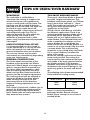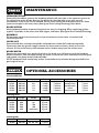
1
360mm BANDSAW
■ STOCK No.36761
■ PART No.BS355A
• INSTRUCTIONS •
IMPORTANT: PLEASE READ THESE INSTRUCTIONS CAREFULLY TO ENSURE THE
SAFE AND EFFECTIVE USE OF THIS TOOL.
12/2000
GENERAL INFORMATION
This manual has been compiled by Draper Tools and is an integrated part of the power tool equipment, which
should be kept with the machine.
This manual describes the purpose for which this tool has been designed and contains all the necessary
information to ensure its correct and safe use.We recommend that this manual is read before any operation of
the machine, before performing any kind of adjustment to the machine, and prior to any maintenance tasks. By
following all the general safety instructions contained in this manual, it will ensure both machine and operator
safety, together with longer life of the tool itself.
All photographs and drawings in this manual are supplied by Draper Tools to help illustrate the operation of the
machine.
Whilst every effort has been made to ensure accuracy of information contained in this manual, the Draper Tool
policy of continuous improvement determines the right to make modifications without prior warning.
360mm
BANDSAW
■ STOCK No.36761
CONTENTS:
■ PART No.BS355A
Page No.
Contents/Declaration .......................................................................................1
Specification/Guarantee...................................................................................2
Power Supply ...................................................................................................3
General Safety Instructions ..............................................................................4
Additional Safety Rules ....................................................................................5
Unpacking and Checking Contents..................................................................6
Getting to Know your Bandsaw.........................................................................7
Assembly .........................................................................................................8
Operation and Use ......................................................................................9-12
Tips on Using Your Bandsaw ......................................................................13-14
Maintenance/Optional Accessories................................................................15
DECLARATION OF CONFORMITY
We
Draper Tools Ltd. Hursley Road, Chandler’s Ford, Eastleigh, Hampshire.
SO53 1YF. England.
Declare under our sole responsibility that the product:
Stock No:- 36761.
Part No:- BS355A.
Description:- Bandsaw.
To which this declaration relates is in conformity with the following directive(s)
98/37/EC & 89/336EEC.
JOHN DRAPER
Managing Director
17/03/99
-1-
SPECIFICATION
The Draper Tools policy of continuous improvement determines the right to change specification
without notice.
Part No. ................................................................................................................BS355A
Stock No...................................................................................................................36761
Maximum cutting height........................................................................................139mm
Throat depth..........................................................................................................360mm
Motor size ................................................................................................375W induction
Blade Length........................................................................................................1784mm
Table size ......................................................................................................400x400mm
Disc size ................................................................................................................152mm
Table tilt....................................................................................................................0-45°
Disc table tilt ............................................................................................................0-45°
Speeds (rpm) ........................................................................................3 (160, 750, 1200)
Nett/Gross weight................................................................................................30/32kg
Sound pressure level ........................................................................................<70db(A)
ALWAYS WEAR EAR AND EYE PROTECTION
GUARANTEE
Draper machine tools have been carefully tested and inspected before shipment and are
guaranteed to be free from defective materials and workmanship for a period of 12 months from
the date of purchase except where tools are hired out when the guarantee period is ninety days
from the date of purchase.
Should the machine develop any fault, please return the complete tool to your nearest authorized
warranty repair agent or contact Draper Tools Limited, Chandler's Ford, Eastleigh, Hampshire,
SO53 1YF. England. Telephone: (023) 8026 6355.
If upon inspection it is found that the fault occurring is due to defective materials or workmanship,
repairs will be carried out free of charge. This guarantee does not apply to normal wear and tear,
nor does it cover any damage caused by misuse, careless or unsafe handling, alterations,
accident, or repairs attempted or made by any personnel other than the authorised Draper
warranty repair agent.
This guarantee applies in lieu of any other guarantee expressed or implied and variations of its
terms are not authorised.
Your Draper guarantee is not effective unless you can produce upon request a dated receipt or
invoice to verify your proof of purchase within the 12 month period.
Please note that this guarantee is an additional benefit and does not affect your statutory rights.
Draper Tools Limited
-2-
POWER SUPPLY
CONNECTING YOUR MACHINE TO THE POWER SUPPLY: (230V)
To eliminate the possibility of an electric shock your machine has been fitted with a BS
approved, non rewireable moulded plug and cable which incorporates a fuse, the value
of which is indicated on the pin face of the plug. Should the fuse need to be replaced an
approved BS1362 fuse must be used of the same rating, marked thus
.
The fuse cover is detachable, never use the plug with the cover omitted. If a replacement
fuse cover is required, ensure it is of the same colour as that visible on the pin face of the
plug (i.e. red). Fuse covers are available from your Draper Tools stockist.
If the fitted plug is not suitable, it should be cut off and destroyed. *The end of the cable
should now be suitably prepared and the correct type of plug fitted. See below.
*WARNING:
A plug with bare flexible wires exposed is hazardous if engaged in a live power socket
outlet.
WARNING: THIS APPLIANCE MUST BE EARTHED.
Green & Yellow - Earth, Blue - Neutral, Brown - Live.
As these colours may not correspond with the coloured markings identifying the
terminals in your plug, proceed as follows:
The wire which is coloured green & yellow must be connected to the terminal in the plug
which is marked with the letter ‘E’ or by the earth symbol
or coloured green or
green and yellow.
The wire which is coloured blue must be connected to the terminal which is marked with
the letter ‘N’ or coloured black or blue.
The wire which is coloured brown must be connected to the terminal which is marked
with the letter ‘L’ or coloured red or brown.
N.B. Three phase machines must be connected by a qualified electrician.
Ampere rating
(on Name plate)
Extension cable length
7.5M
15M
22.5M
30M
45M
3
6
10
13
0.75
0.75
0.75
0.75
0.75
0.75
0.75
0.75
0.75
1.25
1.0
1.0
1.0
1.25
1.5
1.25
1.5
1.5
1.5
2.5
-3-
GENERAL SAFETY INSTRUCTIONS
FOR POWER TOOLS
WARNING
Please read the following instructions carefully, failure to do so could lead to serious personal injury.
IMPORTANT
Draper Tools Limited recommends that this machine should not be modified or used for any application other
than that for which it was designed. If you are unsure of its relative applications do not hesitate to contact us in
writing and we will advise you.
1.
2.
3.
4.
5.
6.
7.
8.
9.
10.
11.
12.
13.
14.
KNOW YOUR POWER TOOL
Read and understand the owner's manual and labels
affixed to the tool. Learn its application and limitations as
well as the specific potential hazards peculiar to this tool.
KEEP WORK AREA CLEAN
Cluttered areas and benches invite accidents. Floors must
not be slippery due to oil or sawdust.
AVOID DANGEROUS ENVIRONMENTS
Do not use power tools in damp or wet locations, or
expose them to rain. Keep work area well lit. Provide
adequate space surrounding the work area. Do not use in
environments with a potentially explosive atmosphere.
KEEP CHILDREN AWAY
All visitors should be kept a safe distance from work area.
STORED TOOLS
When not being used, all tools should be stored in a dry,
locked cupboard or out of the reach of children.
WEAR PROPER CLOTHING
Do not wear loose clothing, neckties or jewellery (rings,
wristwatches) to catch in moving parts. NONSLIP footwear
is recommended.Wear protective hair covering to contain
long hair. Roll long sleeves above the elbow.
USE SAFETY GOGGLES (Head Protection)
Wear CE approved safety goggles at all times. Normal
spectacles only have impact resistant lenses, they are
NOT safety glasses. Also, use face or dust mask if
application is dusty and ear protectors (plugs or muffs)
during extended periods of operation.
NOISE LEVELS
Some types of machines may have high noise levels when
working. In such cases ear protection must be worn.
VIBRATION LEVELS
Hand held power tools produce different vibration levels.
You should always refer to the specifications and relevant
Health and Safety guide.
DUST EXTRACTION
If your tool is fitted with a dust extraction fitting, always
ensure that it is connected and being used with a dust
extractor.Vacuum cleaners can be used if suitable for the
material being extracted.
PROTECT YOURSELF FROM ELECTRIC SHOCK
When working with power tools, avoid contact with any
earthed items (e.g. pipes, radiators, hobs and
refrigerators, etc.). If you are using a power tool in
extreme conditions (e.g. high humidity or generating
metal dust), always use an RCD (residual current device)
at the power socket.
STAY ALERT
Always watch what you are doing and use common sense.
Do not operate a power tool when you are tired or under
the influence of alcohol or drugs.
WHEN WORKING OUT OF DOORS
Only use extension leads designed for that purpose.
ACCESS TO MAINS SOCKET
If a stationary machine is fitted with a moulded plug and
cable, the machine should not be positioned so that
access to the mains socket is restricted.
15.
16.
17.
18.
19.
20.
21.
22.
23.
24.
25.
26.
27.
28.
29.
30.
DISCONNECT POWER TO THE TOOL
When not in use, before servicing and when changing
accessories such as cutters, etc.
AVOID ACCIDENTAL STARTING
Make sure the switch is in the OFF position before
plugging the machine into the power supply.
NEVER LEAVE MACHINE RUNNING UNATTENDED
Turn power off. Do not leave machine until it comes to a
complete stop.
DO NOT ABUSE THE CORD
Never carry the tool by the power cable or pull it from
the socket. Keep the power cable away from heat, oil and
sharp edges.
NEVER STAND ON TOOL
Serious injury could occur if the tool is tipped or if the
cutting tool is accidentally contacted. Do not store
materials above or near the tool, so that it is necessary to
stand on the tool to reach them.
CHECK DAMAGED PARTS
Check for damage to parts, breakage of parts, mountings
and any other conditions that may affect its operation.
A guard or other part that is damaged should be properly
repaired or replaced.
KEEP GUARDS IN PLACE
And in working order.
MAINTAIN TOOLS WITH CARE
Keep tools sharp and clean for the best and safest
performance. Follow instructions for lubricating and
changing accessories. All extension cables must be
checked at regular intervals and replaced if damaged.
Always keep the hand grips on the tool clean, dry and
free of oil and grease.
USE RECOMMENDED ACCESSORIES
Consult the owners manual for recommended
accessories. Follow the instructions that accompany the
accessories. The use of improper accessories may cause
hazards.
REMOVE ADJUSTING KEYS AND WRENCHES
Form a habit of checking to see that keys and adjusting
wrenches are removed from the tool before turning it on.
SECURE WORK
Use clamps or a vice to hold work. This frees both hands
to operate the tool.
DO NOT OVERREACH
Keep proper footing and balance at all times.
USE RIGHT TOOL
Do not force the tool or attachment to do a job for which it
was not designed.
DO NOT FORCE TOOL
It will do the job better and safer at the rate for which it
was designed.
DIRECTION OF FEED
Feed work into a blade or cutter against the direction of
rotation of the blade or cutter only.
WHEN DRILLING OR SCREWING INTO WALLS
Always make sure there is no danger of hitting any hidden
power cables, water or gas pipes in the wall.
IMPORTANT NOTE
Residual Risk. Although the safety instructions and operating manuals for our tools contain extensive
instructions on safe working with power tools, every power tool involves a certain residual risk which can not be
completely excluded by safety mechanisms. Power tools must therefore always be operated with caution !
-4-
ADDITIONAL SAFETY RULES FOR
BANDSAWS/DISCS AND STRIP SANDERS
14. Permanently fix your bandsaw to a
bench before performing cutting
operations. (See ‘Fastening to a
Workbench’, page 9).
1. Lower the blade guard to within
approximately 3mm above the
material being cut.
2. Always keep hands and fingers away
from the saw blade, especially when
coming to the end of a cut.
15. Use in a well ventilated area and
dust extraction to minimise airborne
dust.
3. Use a push stick or piece of scrap
wood to do the pushing and guiding
when sawing small pieces which
would otherwise require the fingers
to be close to the saw.
16. Before freeing any jammed material
turn switch off, disconnect from
power supply and wait for all moving
parts to stop.
17. Before starting to cut, watch the saw
while it runs. If it makes an
unfamiliar noise or vibrates
excessively, stop immediately. Turn
the saw off and disconnect from the
power supply. Do not attempt to use
the saw until the problem has been
rectified.
4. Switch the machine off and let the
blade come to a stop before
removing scrap pieces from the
table.
6. Make all adjustments and set ups
with the power off and plug removed
from the power supply, such as tilting
the table, adjusting the saw blade
guards and blade guides.
18. Repair or servicing required on this
product should be made only by a
qualified person.When servicing
use only identical replacement
parts.
7. Disconnect the machine before
adjusting the blade tension and the
blade tracking.
8. The cover housing must be in place
and securely fastened before
performing any operation.
19. Do not use saw bands which are
damaged or deformed.
20. Replace table insert when worn.
9. Securely lock all adjustable parts so
they cannot loosen. This will prevent
distraction from the operation.
21. When cutting round timber use a
suitable device to prevent twisting of
the workpiece.
10. When sawing curves, make relief
cuts to allow removal of scrap
material. This will help prevent
undue twisting or binding of the saw
blade. The relief cuts are made
before starting the curved saw cut.
22. When bevel cutting with the table
inclined, place the guide on the
lower part of the table .
23. Connect bandsaws to a dust
collecting device when operating.
11. Hold material firmly and feed into
the blade at a moderate speed.
24. Do not operate the machine when
the door or guard protecting the
band is not closed.
12. Be sure to use the correct blade size
and type for the application.
13. Do not saw any material that does
not have a flat surface, unless a
suitable support is used.
-5-
UNPACKING AND CHECKING CONTENTS
WARNING
For your own safety, do not connect the plug to the power supply until all the assembly
steps are completed and you have read and understood the safety and operational
instructions.
Carefully unpack the bandsaw and all the loose items from the carton. The photograph
below, illustrates the bandsaw and all the loose parts. Refer to Fig.1.
Check that all the parts are present. If any parts are damaged or are missing, please call
the Draper Helpline on (023) 8049 4344.
Fig.1.
-6-
GETTING TO KNOW YOUR BANDSAW
Fig.2.
Fig.2.
1. No Volt switch
2. Drive wheel & sanding disc
3. Sanding guard (not shown)
4. Sanding table
5. Sanding table lock knob
6. Motor pulley
7. Idler wheel
8. Lower back bearing
9. Lower blade guides
10. Upper blade guides
11. Upper back bearing
12.
13.
14.
15.
16.
17.
18.
19.
20.
21.
22.
Blade guard
Tracking wheel
Tension bolt
Height adjustment lock knob
Tracking bolt
Motor
Work table
Tilt indicator
Table lock knob
Power on/off switch lock
Sawdust extraction outlet
-7-
ASSEMBLY
Your bandsaw is supplied assembled except
for the work and sanding table. To assemble
the worktable to the bandsaw:
1. Remove the table lock knob $, spring
% and spring support bush & from the
table support at the rear of the bandsaw
(Fig.3).
2. Remove the hex socket head table
alignment screw and clamp from the
underside of the worktable. Standing at
the rear of the of the bandsaw with the slot
of the table facing the machine, fix the
table so that the blade passes through the
table slot, and the table support rod '
goes through the curved slot in the tilt
indicator (Fig.4).
3. Replace the spring support bush & with
the large flange end facing towards the tilt
indicator.
4. Push the spring % over the spring
support bush &.
5. Screw the lock knob $ onto the table
support (Fig.5, 5A).
Fig.3.
& %
$
Fig.4.
'
Fig.5.
Fig.5A.
FASTENING TO WORKBENCH (fixing
bolts not supplied)
Your bandsaw should be bolted to a solidly
built workbench. Mounting holes are
provided in the base of the machine. Large
flat washers should be used between the bolt
heads and the base to fasten more securely
and prevent any damage to the bandsaw.
Tighten snugly but do not overtighten
SPEEDS
Your bandsaw is equipped with pulley steps
for three speeds - adequate for all normal
working requirements. Always use low speed
for cutting nonferrous metals. Medium and
high speeds are used for other materials,
depending on blade type.
-8-
%
&
%
& $
OPERATION & USE
ON/OFF SWITCH
When key is in the off/locked position, it
will prevent unauthorized operation of
the bandsaw (Fig.6).
Fig.6.
Fig.7.
The bandsaw is fitted with a no volt
switch. In the event of a power supply
failure the bandsaw will have to be
manually re-started (Fig.7).
CHANGING SPEEDS
1. Turn the main power switch off and
disconnect from the power supply.
2. Remove the front cover.
3. Refer to Fig.8. and check which pulley
steps to use for the desired speed
and adjust as required.
4. Change the belt on the motor pulley
or drive wheel will allow you to move
it from a larger diameter step to a
smaller step.
5. Replace the front cover.
Fig.8.
DRIVE WHEEL
-9-
MOTOR PULLEY
OPERATION & USE
CHANGING BLADES
1. Turn the main power switch off and
disconnect from the power supply.
2. Remove front cover.
3. Remove the upper blade guard (,
loosen locking screw ) and adjust the
upper support bearing * away from
the blade (Fig.9).
4. Loosen the upper and lower blade
guide locking screws + and move the
blade guides away from the blade
(Fig.10).
5. Loosen locking screw , and adjust the
lower support bearing - away from
the blade (Fig.10).
6. Using the hex key supplied . turn
the blade tensioning bolt / clockwise
to decrease the blade tension (Fig.11).
7. Remove the old blade. Slip the new
blade over the three wheels, placing
the blade as close as possible to the
centre of the wheels (make sure the
teeth face the table).
8. Turn the tensioning bolt /
anticlockwise until the blade is
tensioned.
9. Rotate the idler wheel by hand until the
blade centres correctly on all three
wheels. If the blade does not track
correctly, adjust the tracking bolt 0
while rotating the idler wheel until it
does so (Fig.12).
10. Adjust the top * and bottom blade
support bearings so they are just
touching the rear of the blade and lock
in place.
11. Adjust the blade guides so there is a
gap of approx. 1mm between each
guide and the blade and lock in place.
12. Reassemble the blade guard (.
13. Replace the front cover.
- 10 -
Fig.9.
)
(
*
Fig.10.
+
,
Fig.11.
-
.
/
Fig.12.
0
OPERATION & USE
MITRE GUIDE
Most cross cut work, especially with small
pieces of material are more easily controlled
with the aid of the mitre guide 3. The guide
is graduated to 45˚ for assistance in cutting
both left and right hand angles. Fig.13.
RIP FENCE
True straight line rip cutting is best done by
guiding the work against the rip fence 2.
The fence can also be used for cutting off
exact widths. Fig.14.
WARNING: The supporting surface where the
band saw is mounted, should be examined
carefully after mounting to ensure that there is
no movement during use. If any tipping or
walking is noted, secure the workbench or
supporting surface before operating
bandsaw.
CIRCLE CUTTING ATTACHMENT
The circle cutting attachment 4 mounts on
the arm of the upper guide block 5.
Accurate circles can be cut out with a radius
of 50mm - 200mm
Make the first cut to the perimeter of the
circle freehand before setting the pivot pin
6 of the attachment into the work. The pivot
pin must be aligned exactly to the right of the
blade tips. If the pivot is too far back, the
blade will run outside the desired
circumference. If too far forward, the blade
will run inside.
USING YOUR BANDSAW AS A POWER BELT
SANDER
Remove the blade and fit a sanding belt 7
as explained in CHANGING BLADES
(page10).
However, make sure that the blade support
bearings and the blade guides, both upper
and lower, are well clear of the abrasive
sanding belt. Two sanding stops are available,
one straight and one slightly curved. Screw
the stop into the threaded hole in the
worktable near the table insert with the hex
screws provided with the sanding kit. Adjust
the stop so that the belt just rests against it.
- 11 -
Fig.13.
3
Fig.14.
2
Fig.15
5
4
6
Fig.16.
7
OPERATION & USE
Remove the saw blade as explained in
CHANGING BLADES (page11).
Remove the sanding disc guard from the
front cover. Mount the support rod 8 of
the sanding table through the hole under
the sanding disc. Tighten the table lock
knob at the left hand side of the bandsaw
until the table is held firmly.
The sanding table is slotted for use with the
mitre guide supplied with your bandsaw.
The sanding table can be tilted to 45° for
bevel and compound mitre sanding.
For best results, set the bandsaw at high
speed. (See CHANGING SPEEDS page 9).
Replacement sandpaper discs are available
from the Draper Stockist (see optional
accessories page15). They can be obtained
in four grits and are self-adhesive so that no
glue is required to fix them to the aluminium
disc.
- 12 -
8
Fig.17.
TIPS ON USING YOUR BANDSAW
WORKTABLE
The worktable is a 400x400mm
aluminium die-casting. It supports the
material being cut and is grooved to
accept a mitre guide and rip fence. The
rip fence can be attached to both the
front and rear of the table. The table can
be tilted to every angle from 0-45°
making possible a large variety of bevel
and compound angle cuts. The tilt
indicator beneath the table shows the
angle setting. The centre of the
worktable is protected with a table
insert, easily and economically replaced
if damaged.
TIPS ABOUT BANDSAW BLADES
The size of a band saw blade is denoted
by width, length and thickness. This
bandsaw uses blades which are 1785mm
long, 0.4mm thick and from 6 - 13mm
wide. The number of teeth per inch and
the type of tooth determines the
application of the blade.
A wide choice of blades are available
for different applications. There is no
general purpose bandsaw blade which
is suitable for all operations. Narrow
blades will cut to a tighter radius than
wider blades. Finer toothed blades will
make a smoother, but slower, cut than
coarse blades. As a wide blade has
more contact with the blade guides, it is
easier to cut a true straight line than with
a narrow blade. This is particularly
important in rip-cutting when the blade
has a natural tendency to follow the
grain of the wood.
Blades for cutting hard materials have
more teeth per inch. For cutting thin
hard materials, the number of teeth per
inch needs to be much greater than for
the thicker material. If the distance
between each tooth is greater than the
thickness of the material being cut, the
teeth may grab in the work and break
off.
The following chart shows recommended
blade widths for cutting curves.
SAWDUST EXTRACTION OUTLET
It is recommended that this is used. It
can be connected to a vacuum cleaner
which will provide fast and efficient
removal of sawdust from your machine.
The vacuum cleaner may be used
continuously or intermittently depending
upon your requirements.
INTERNAL CONSTRUCTION
The three wheel construction of this
bandsaw makes possible the 360mm
throat and 140mm depth of cut capacity
within a compact bench mounted unit.
The drive wheel is powered by a belt
from the motor pulley. Both the drive
wheel and the idler wheel are fixed in
position and do not require adjustment.
The tracking wheel can be adjusted to
centre the blade on the three wheels
when running. Because of the selftensioning feature of this bandsaw,
frequent tracking adjustments are not
required.
Each wheel is fitted with a rubber tyre to
prevent the blade from slipping and to
protect the sharp edges of the blade
teeth. These tyres are easily replaced if
they become torn or worn.
Width of Blade
Min. Radius of Curve
6mm
10mm
13mm
25mm
Since it is nearly impossible to
resharpen blades, discard all blunt
blades. Never attempt to use a bent or
cracked blade.
- 13 -
TIPS ON USING YOUR BANDSAW
the table it will help support the work
against slip. The width of cut indicator
shows the distance between the blade
and the rip fence at the table surface.
For all cutting operations the upper
blade guard should be adjusted to just
clear the work being cut (approx. 3mm
or 1⁄8"). Not only does this provide the
best operator safety, but it also brings
the blade guides closer to the work
giving more accurate results and easier
control.
Use both hands to feed the workpiece
into the blade. The work must be held
flat on the table at all times to prevent
binding of the blade. Use a steady even
pressure just sufficient to keep the blade
cutting at full speed.
Always use a rip fence or mitre guide
where possible to eliminate any
sideways slip of the work. This is most
important when the table is tilted to an
angle.
Always plan work ahead. The
tradesmans’ rule is “measure twice, cut
once”. It is best to finish a cut in one
continuous operation, but frequently
backtracking will be necessary. Turn off
the motor and allow the blade to come
to a complete stop before backing the
blade out of the cut.
Remember that the blade removes
material during the cut. This gap created
by the blade is called the kerf and must
be allowed for when cutting to exact
sizes. Plan your cut so that the kerf is to
the scrap side of the line you wish to cut.
If necessary, allow a little more for finish
sanding.
CROSS CUTTING
This term refers to the cutting of timber
across the grain. This type of cut can also
be made freehand or with the aid of the
mitre guide. The mitre guide can be
adjusted to a 45˚ angle to assist during
mitre cuts, and with compound mitre
cuts.
Make sure the work is held firmly
against the table and against the face of
the mitre guide. Be careful to keep your
fingers away from the blade, particularly
at the end of the cut.
FREEHAND SAWING
The ease with which many different and
varied shapes can be cut is one of the
most important features of the bandsaw.
Select a blade suitable for cutting the
smallest radius in the work you have
planned.
When freehand cutting always feed the
work slowly so that the blade can follow
the line you wish to saw. Make sure not
to drag the work off line forcing the
blade sideways, or twisting it.
In many cases, it is helpful to rough cut
about 6mm away from the line in difficult
curves and corners. In the case of very
sharp curves which may be too tight for
the blade, make relief cuts onto the face
of the curve so that these scraps will fall
as the final radius is sawn.
RIP SAWING
This term refers to the cutting of timber
with the grain rather than across the
grain.You can rip wood freehand to a
previously drawn line, but best results
are obtained by using the rip fence. If
the table is level, set the rip fence to the
left hand side of the blade. This allows
you to use your right hand to hold the
work firmly against the fence. The width
of cut indicator on the front of the
worktable shows the distance between
the blade and the right hand edge of the
timber.
When cutting a bevel rip, with the table
tilted at any angle up to 45˚, set the rip
fence to the right hand side of the blade
if the width of the workpiece allows it.
With the fence on the downhill side of
CUTTING NONFERROUS METALS
Metal must only be cut at the lowest
speed on your bandsaw. Never attempt
metal sawing at wood cutting speed your blade will burn up very quickly.
Other than speed and correct blade
selection, metal sawing is much the
same as wood sawing, however, the rate
at which you feed the work into the
blade must be reduced to only as fast as
the blade can cut.
Also, metals do not have the ‘give’ that
timber has, so the work must be held
very firmly to prevent twisting or
misalignment of the blade while
feeding.
- 14 -
MAINTENANCE
CHANGING TYRES
Eventually the rubber tyres on the bandsaw wheels will wear due to the constant contact of
the sharp teeth of the blade. Remove the blade, lift the edge of the tyre with a small
screwdriver and the tyre can be worked off the wheel easily.We recommend that the three
tyres be changed at the same time. (See Spare Parts Listing/Drawing). Refit blade
BLADE GUIDES
Blade guides should be inspected regularly for wear or chipping.When replacing guides
replace all guides at the same time, both upper and lower. (See Spare Parts Listing/Drawing).
BEARINGS
All bearings used in the construction of your bandsaw and its motor are sealed and
lubricated for life.
CLEAN OUT
Accumulated dust and chips should be removed from inside the bandsaw frequently.
Disconnect from the power supply, remove the front cover and use a brush or vacuum
cleaner. At the end of every work session clean sawdust away from the motor vents.
BLADE BRUSH
Ensure that you check on a regular basis that the brush is in full contact with the bandsaw
blade and wheel. This will help to keep the tyres on the wheel clean and assist with the quick
and smooth run down of the bandsaw blade.
NOTE: Bandsaw blade should stop within 10 seconds of the machine being switched off as
per original set up.
OPTIONAL ACCESSORIES
Bandsaw Blades
Stock No. Part No.
25766
BB1785
25767
BB1785
25768
BB1785
25769
BB1785
25770
BB1785
Blade width
1/4"
3/8"
1/2"
1/4"
1/2"
Teeth
6 skip
6 skip
6 skip
6 skip
6 skip
Grade
60
80
100
120
*Assorted
Quantity
5 pack
5 pack
5 pack
5 pack
5 pack
Grade
60, 80, 120
Quantity
3 pack
Blade length Application
1785mm
wood/plastic
1785mm
wood/plastic
1785mm
wood/plastic
1785mm
metal
1785mm
wood/metal
Sanding Discs
Stock No.
25971
25972
25973
25974
25975
Part No.
SD6
SD6
SD6
SD6
SD6
*1x60, 2x80, 1x100, 1x120
Sanding Belt
Stock No.
25988
Part No.
SB1785
- 15 -
Quantity
1 pack
1 pack
1 pack
1 pack
1 pack
NOTES
- 16 -
NOTES
- 17 -
NOTES
- 18 -
DRAPER TOOLS LIMITED,
Hursley Road, Chandler's Ford, Eastleigh, Hants. SO53 1YF. U.K.
Helpline: (023) 8049 4344.
Sales Desk: (023) 8049 4333.
General Enquiries: (023) 8026 6355.
Fax: (023) 8026 0784.
http://www.draper.co.uk
e-mail: [email protected]
YOUR DRAPER STOCKIST
©Published by Draper Tools Ltd.
No part of this publication may be reproduced,
stored in a retrieval system or transmitted in
any form or by any means, electronic, mechanical
photocopying, recording or otherwise without prior
permission in writing from Draper Tools Ltd.